Embed Size (px)
Citation preview
Design and testing of a fast tool servo for diamond turning S.R. Patterson* and E.B. Magrabl"
A self-contained and independently servo-operated diamond tool holder was built to increase the resolution and accuracy of a precision lathe. Its static and dynamic repeatability over a range of +_ 50 IJin (1.27 izm) is better than 0.05 pin (1.3 nm). Its frequency distortion from 0-100 Hz is less than 1.0 pin (25 nm) for a peak displacement of less than 28 iJin (0. 71 iJm).
Keywords: servosystems, piezoelectric actuator, diamond tools, resolution, accuracy
The use of feedback correction of tool position to increase the resolution and accuracy of high- precision machine tools has created the need for actuators capable of moving the machine's ele- ments over very small distances precisely. When the bandwidth of the correction signal is small the basic moving element drivers of the machine tool often perform their function adequately. When the bandwidth requirement is large, however, (as, for instance, when compensating for some spindle error motions) it becomes difficult to accelerate and decelerate these moving elements to their proper positions. The fast tool servo (FTS), which is a self-contained and independently operated posi- t ioning device, was designed and built to eliminate this problem by moving only the small mass of the tool bit itself.
FTS design
Design criteria
The FTS was designed to act as a tool post for a large precision lathe 1'2, A signal from the lathe con- trol system indicates the tool bar position error along the FTS axis, and is used as an input to the FTS controller. The resulting motion of the FTS removes the surface-normal tool position error. For its cur- rent application it is required that the FTS position a diamond tool over a range of _ 1.27/lm (50 pin) with a resolution of 2.5 nm (0.1/1in). To correct the anticipated spindle error motion at a spindle speed of 150 r/rain, a bandwidth of 100 Hz was deemed necessary. As a contribution to the overall surface finish error budget, the position noise of the FTS must be less than 2 nm (0.08/Jin) RMS. Finally, since the distance between the tip of the diamond tool and the FTS base is not accounted for in the position feedback loop of the host machine, the FTS should have a long-term stability and absolute accuracy of the same order as its resolution, ie 2.5 nm (0.1 pin). To permit use of the FTS as a toolholder for turning operations, the stiff- ness along all three axes must be high during oper-
* Lawrence Livermore National Laboratory, Liverrnore, California 94550, USA 7" Center for Manufacturing Engineering, National Bureau of Standards, Gaithersburg, Maryland 20899, USA
JULY 1985
ation to prevent chatter. Therefore, a stiffness of 106 pounds/inch was specified for both the passive lateral and the active axial stiffnesses.
Mechanical design
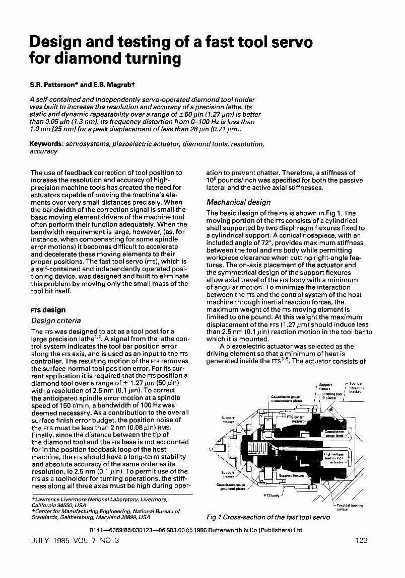
The basic design of the FTS is shown in Fig 1. The moving portion of the FTS consists of a cylindrical shell supported by two diaphragm flexures fixed to a cylindrical support. A conical nosepiece, with an included angle of 72 ° , provides maximum stiffness between the tool and FTS body while permitting workpiece clearance when cutting right-angle fea- tures. The on-axis placement of the actuator and the symmetrical design of the support flexures allow axial travel of the FTS body with a minimum of angular motion. To minimize the interaction between the FTS and the control system of the host machine through inertial reaction forces, the maximum weight of the FTS moving element is limited to one pound. At this weight the maximum displacement of the FTS (1.27 pm) should induce less than 2.5 nm (0.1 pin) reaction motion in the tool barto which it is mounted.
A piezoelectric actuator was selected as the driving element so that a minimum of heat is generated inside the FTS 3-5. The actuator consists of
Fig 1 Cross-section of the fast tool servo
01414359/85/0301234-06 $03.00 @ 1985 Butterworth & Co (Publishers) Ltd
VOL 7 NO 3
surface
123
Patterson and Magrab - - fast tool servo
a 12.7 mm (0.5 inch) long stack of lead-zirconate- titanate (ezT)ceramic elements supplied by Burleigh Instruments Inc. This actuator provides _+1.27 pm of travel when a voltage between 0 and 1000 V is applied. The stack is designed to increase its length with the applied voltage so that any fai- lure in the voltage supply will result in retraction of the tool. The diameter of the PZT stack and the nature of its connection to the FTS body is deter- mined by the bandwidth requirement. To allow the control system to have a bandwidth of 100 Hz it is desirable that the first natural resonance of the FTS be above 1 kHz. The primary resonance is attri- buted to the simple oscillator consisting of the mass of the FTS body and the parallel springs formed by the PZT actuator and the flexures. The compliance of the actuator comes from the elastic- ity of the PZT material and the Hertzian strain in the contact between the actuator and FTS body. The contact compliance has been reduced by using a large-nose radius on the tip of the actuator and by preloading it with an axial force from the support flexures. A minimum ezT stack diameter of approxi- mately 6.3 mm provides stiffness sufficient to place the resonance above 1 kHz when supporting the maximum FTS body weight of 1 Ib (0.454 kg). With the addition of some necessary high voltage insula- tion and a support structure the overall diameter of the actuator increases to 12.7 mm.
The combination of the piezoelectric actuator and the flexure supports provides an actuation sys- tem free of mechanical stiction; however, it is still affected by hysteresis. In addition, the PZT ceramic used for the actuator has a relatively large coeffi- cient of thermal expansion. These temperature dependent and nonlinear effects tend to be attenuated by the closed loop nature of the FTS. The temporal and thermal stability of the FTS is thus dependent upon the characteristics of the capacitance gauge and the materials connecting it to the tool tip and support base. The capacitance gauge is a differential device consisting of a pair of measurement plates attached to the support cylin- der and positioned between a pair of annular, grounded plates that are attached to the FTS body. The measurement plates consist of an annular quartz disk with vapour-deposited chromium elec- trodes on each surface. When the measurement plates are centred, the air gap between the mea- surement and the grounded plates is 50/~m, and the effective plate area is 5.8 cm 2. To reduce the thermal sensitivity in the path between the plates, tool tip and support base, both the FTS body and the inner support cylinder are constructed of superinvar.
The remainder of the mechanical design is largely dictated by practical hardware considera- tions, the desired lateral stiffness and the need to avoid plastic deformation in the support flexures. The base of the FTS is located radially by a precision toroidal joint, while axial and angular location is accomplished with three pads contacting the back of the base flange. A similar design is used for a detachable tool holder. The outside diameter of the FTS body is 5 cm (2 inches) and the total moving weight is 0.38 kg (0.84 Ib).
Elect ron ic des ign
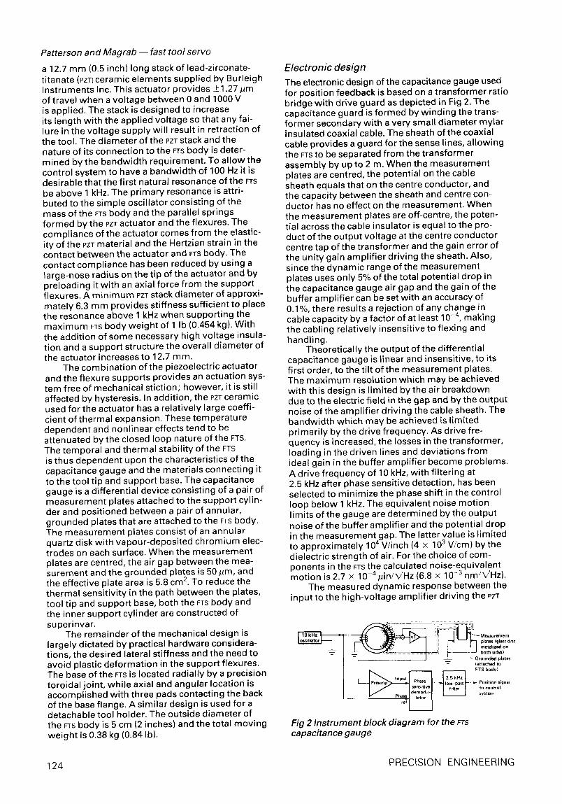
The electronic design of the capacitance gauge used for position feedback is based on a transformer ratio bridge with drive guard as depicted in Fig 2. The capacitance guard is formed by winding the trans- former secondary with a very small diameter mylar insulated coaxial cable. The sheath of the coaxial cable provides a guard for the sense lines, allowing the FTS to be separated from the transformer assembly by up to 2 m. When the measurement plates are centred, the potential on the cable sheath equals that on the centre conductor, and the capacity between the sheath and centre con- ductor has no effect on the measurement. When the measurement plates are off-centre, the poten- tial across the cable insulator is equal to the pro- duct of the output voltage at the centre conductor centre tap of the transformer and the gain error of the unity gain amplifier driving the sheath. Also, since the dynamic range ofthe measurement plates uses only 5% ofthe total potential drop in the capacitance gauge air gap and the gain of the buffer amplifier can be set with an accuracy of 0.1%, there results a rejection of any change in cable capacity by a factor of at least 10 -4, making the cabling relatively insensitive to flexing and handling.
Theoretically the output of the differential capacitance gauge is linear and insensitive, to its first order, to the tilt of the measurement plates. The maximum resolution which may be achieved with this design is limited by the air breakdown due to the electric field in the gap and by the output noise of the amplifier driving the cable sheath. The bandwidth which may be achieved is limited primarily bythe drive frequency. As drive fre- quency is increased, the losses in the transformer, loading in the driven lines and deviations from ideal gain in the buffer amplifier become problems. A drive frequency of 10 kHz, with filtering at 2.5 kHz after phase sensitive detection, has been selected to minimize the phase shift in the control loop below 1 kHz. The equivalent noise motion limits of the gauge are determined by the output noise of the buffer amplifier and the potential drop in the measurement gap. The latter value is limited to approximately 104 V/inch (4 x 10³ V/cm) by the dielectric strength of air. For the choice of com- ponents in the FTS the calculated noise-equivalent motion is 2.7 x 10 4pin/~/Hz (6.8 x 10 -3 nm/k/Hz).
The measured dynamic response between the input to the high-voltage amplifier driving the PZT
L ~ ~ - - Measurement ~ : : : ~ ~ I plate= (glass disc
i • I rnetalized on
J ~ L t Grounded plates -~ (attached to
_ _ FTS body)
nput Position signal ~ t o control system
Fig 2 Instrument block diagram for the FTS capacitance gauge
124 PRECISION ENGINEERING
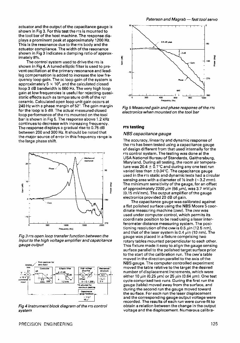
actuator and the output of the capacitance gauge is shown in Fig 3. For this test the FTS is mounted to the tool bar of the host machine. The response dis- plays a prominent peak at approximately 1200 Hz. This is the resonance due to the FTS body and the actuator compliance. The width of the resonance shown in Fig 3 indicates a damping ratio of approx- imately 8%.
The control system used to drive the FTS iS shown in Fig 4. A tuned elliptic filter is used to pre- vent oscillation at the primary resonance and lead- lag compensation is added to increase the low fre- quency loop gain. The DC loop gain of the system is approximately 5 x 10⁴, and the calculated closed loop 3 dB bandwidth is 660 Hz. The very high loop gain at low frequencies is useful for rejecting quasi- static effects such as temperature drift of the PZT ceramic. Calculated open loop unit gain occurs at 240 Hz with a phase margin of 52 °. The gain margin for the loop is 5 dB. The actual measured closed loop performance of the FTS mounted on the tool bar is shown in Fig 5. The response above 1.2 kHz continues to decrease with increasing frequency. The response displays a gradual rise to 0.75 dB between 200 and 300 Hz. It should be noted that the major source of error in this frequency range is the large phase shift.
Phase J
10,
0 500 1000 Frequency (Hz)
I ' 0
90
~ - 1 8 0
' -270 1500 2000
Fig 3 FTS open loop transfer function between the input to the high voltage amplifier and capacitance gauge output
Trim position for Analog i / zero input
bias Controller Elliptic filter High voltage + amplifier
-+ 1 0 V 3 r - I i : \ . _ i I ' I ~ co . . . . dT v I ~ I I y "-__s input I [ mHz 339~j [ 1.2__kHz G m ~ u ~ f n p ~ *G adjusted for
minimum peaking
Cepa©itence , .,i t ;,v,
Fig 4 Instrument block diagram of the FTS control system
.E
1 0 ~ 1 ' , ,
3/4 dB peak
0
-10
-20 , , I 200
Paterson and Magrab - - fast tool servo
I ' ' I ' , O
-90
-3 dB
Phase J ~ % . ~ ' 1 -270
640 /
I I r ; I l 1~ I I [ I I I -360 400 600 800 1000
Frequency(Hz)
-180
Fig 5 Measured gain and phase response of the FTS electronics when mounted on the tool bar
rrs t e s t i n g
NBS capacitance gauge
The accuracy, linearity and dynamic response of the FTS has been tested using a capacitance gauge of design different from that used internally for the FTS control system. The testing was done at the USA National Bureau of Standards, Gaithersburg, Maryland. During all testing, the room air tempera- ture was 20.4 + 0.1°C and during any one test run varied less than +0.04°C. The capacitance gauge used in the FTS static and dynamic tests had a circular sensing area with a diameter of 1/8 inch ( -3 .2 mm). The minimum sensitivity of the gauge, for an offset of approximately 2200/~in (56/~m), was 3.7 mV//~in (0.15 mV/nm). The output amplifier of the gauge electronics provided 20 dB of gain.
The capacitance gauge was calibrated against a flat polished surface using the NBS Moore 5 coor- dinate measuring machine (CMM). The CMM was used under computer control, which permits its coordinate position to be read using a laser inter- ferometer distance measuring system. The posi- tioning resolution of the CMM is 0.5/~in (12.5 rim), and that ofthe laser system is 0.4 pin (10 nm). The gauge was placed in a fixture comprising two rotary tables mounted perpendicular to each other. This fixture made it easy to align the gauge sensing surface parallel to the polished target surface prior to the start of the calibration run. The CMM'S table moved in the direction parallel to the axis of the NBS gauge. The computer controlled experiment moved the table relative to the target the desired number of displacement increments, which were either 10/~in (0.25/~m) or 25 pin (0.64 pm). One test cycle comprised two runs. During the first run the gauge (table) moved away from the surface, and during the second run the gauge moved toward the surface. For each run the laser displacement and the corresponding gauge output voltage were recorded. The results of each run were curve-fit to obtain a relation between the change in the output voltage and the displacement. Numerous calibra-
PRECISION ENGINEERING 125
Patterson and Magrab - - fast tool servo
t ion tests on the gauge over a period of nine months indicated that for a sensit ivi ty at an offset distance corresponding to 10.0 V the percentage standard error of the gauge sensit ivi ty varied less than 0.5%, which corresponds to an uncertainty of approximately 0.9 pin (23 nm) in 50 pin (1300 nm). In spite of this small uncertainty the NBS gauge was calibrated just prior to the start of the static and dynamic tests and the results of this last calib- ration used to determine the FTS displacement.
Stat ic d i sp lacemen t tests
Prior to the dynamic testing, a series of static tests was run to determine the l inearity and repeata- bi l i ty of both the FTS and its associated electronics, and the NBS capacitance gauge and its instrumen- tation and curve-fitted voltage/displacement response.
The FTS and the capacitance gauges were mounted in a steel, L-shaped f ixture in a manner that duplicated the mount ing on the lathe tool bar. The entire f ixture was then placed on a large, thick, steel-topped table of honeycomb construction. The target for the NBS capacitance gauge was a disk polished on one surface and with a concentric cylindrical rod protruding from the opposite sur- face. This rod was inserted into the FTS in place of the diamond cutting tool and held by means of a set screw.
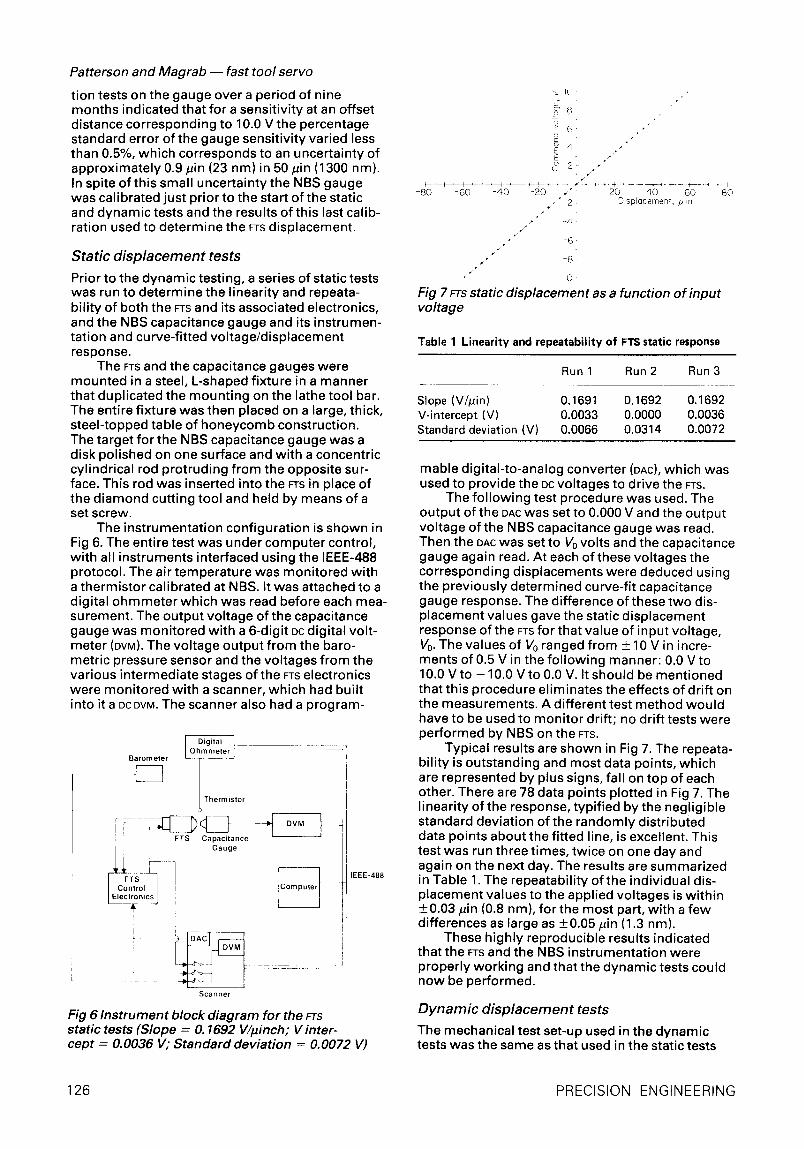
The instrumentat ion configurat ion is shown in Fig 6. The entire test was under computer control, with all instruments interfaced using the IEEE-488 protocol. The air temperature was monitored with a thermistor calibrated at NBS. It was attached to a digital ohmmeter which was read before each mea- su rement. The output voltage of the capacitance gauge was monitored with a 6-digit DC digital volt- meter (DVM). The voltage output from the baro- metric pressure sensor and the voltages from the various intermediate stages of the FTS electronics were monitored with a scanner, which had built into it a DC DVM. The scanner also had a program-
J Thermistor
i FTS Capacitance Gauge
i ~ DAC
i
1 j [
Scanner
Fig 6 Instrument block diagram for the FTS static tests (Slope = O. 1692 V/iJinch; V inter- cept = 0.0036 V; Standard deviation = 0.0072 V)
IEEE-488
"-~ I O
~2
- 80 -60 - 40 -20 . * 20 40 60 810 , " 2 - DisplQcement, ~ in
• - 4
/ " 8 J
- I0
Fig 7 FTS static displacement as a function of input voltage
Table 1 Linearity and repeatability of FTS static response
Run 1 Run 2 Run 3
Slope (V/#in) 0.1691 0.1692 0.1692 V-intercept (V) 0.0033 0.0000 0.0036 Standard deviation (V) 0.0066 0.0314 0.0072
mable digital-to-analog converter (DAC), which was used to provide the DC voltages to drive the FTS.
The fol lowing test procedure was used. The output of the DAC was set to 0.000 V and the output voltage of the NBS capacitance gauge was read. Then the DAC was set to V0 volts and the capacitance gauge again read. At each of these voltages the corresponding displacements were deduced using the previously determined curve-fit capacitance gauge response. The difference of these two dis- placement values gave the static displacement response of the FTS for that value of input voltage, V0. The values of V0 ranged from + 10 V in incre- ments of 0.5 V in the fol lowing manner: 0.0 V to 10.0 V to - 10.0 V to 0.0 V. It should be mentioned that this procedure eliminates the effects of drift on the measurements. A different test method would have to be used to monitor drift; no drift tests were performed by NBS on the FTS.
Typical results are shown in Fig 7. The repeata- bi l i ty is outstanding and most data points, which are represented by plus signs, fall on top of each other. There are 78 data points plotted in Fig 7. The linearity of the response, typif ied by the negligible standard deviation of the randomly distributed data points about the fitted line, is excellent. This test was run three times, twice on one day and again on the next day. The results are summarized in Table 1. The repeatability of the individual dis- placement values to the applied voltages is wi th in +0.03 #in (0.8 nm), for the most part, with a few differences as large as +0.05 #in (1.3 nm).
These highly reproducible results indicated that the FTS and the NBS instrumentation were properly working and that the dynamic tests could now be performed.
D y n a m i c d i sp lacemen t tests
The mechanical test set-up used in the dynamic tests was the same as that used in the static tests
126 PRECISION ENGINEERING
with one additional feature: the L-shaped fixtu re was clamped at three points to the rigid, steel- topped table.
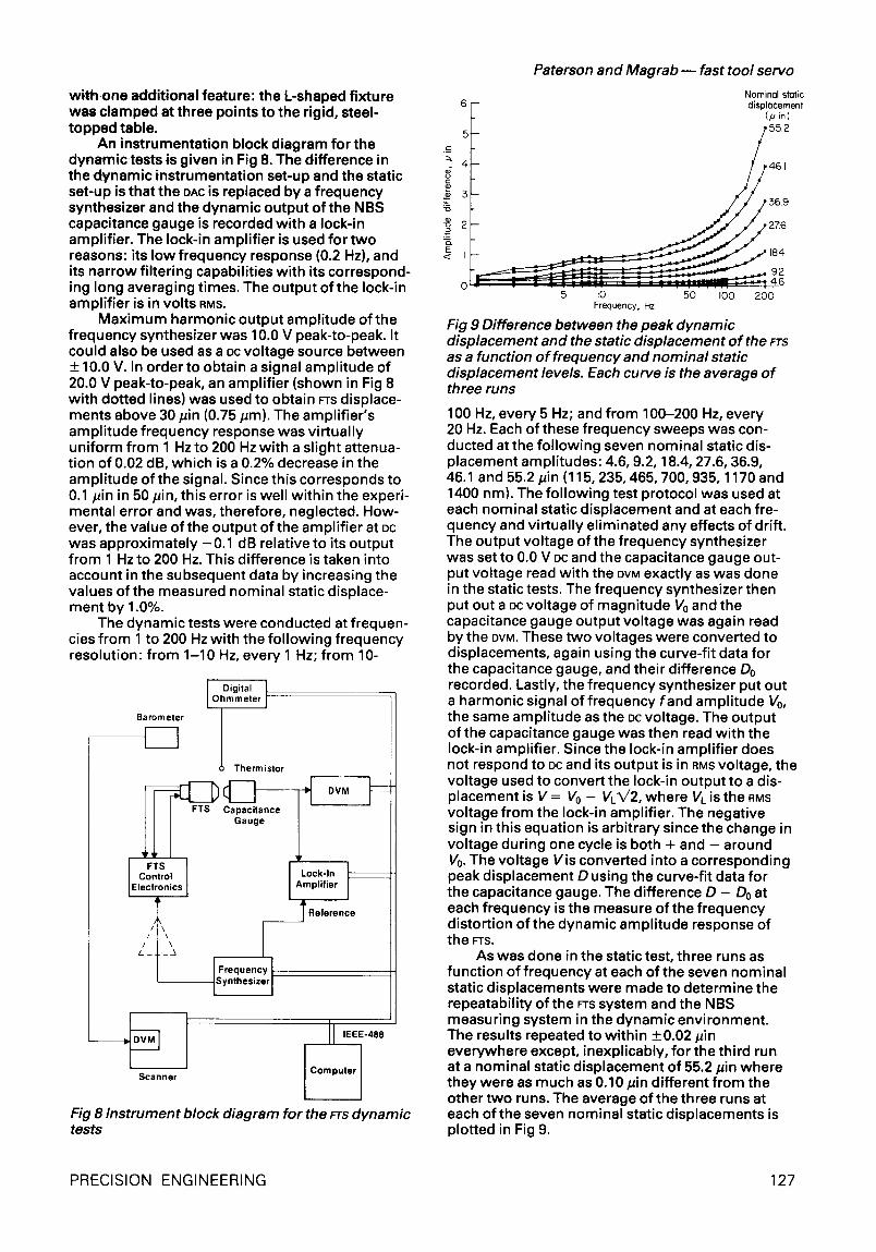
An instrumentation block diagram for the dynamictests is given in Fig 8. The difference in the dynamic instrumentation set-up and the static set-up is that the DAC is replaced by a frequency synthesizer and the dynamic output of the NBS capacitance gauge is recorded with a lock-in amplifier. The lock-in amplifier is used for two reasons: its low frequency response (0.2 Hz), and its narrow filtering capabilities with its correspond- ing long averaging times. The output of the lock-in amplifier is in volts RMS.
Maximum harmonic output amplitude of the frequency synthesizer was 10.0 V peak-to-peak. It could also be used as a DC voltage source between __ 10.0 V. In order to obtain a signal amplitude of 20.0 V peak-to-peak, an amplifier (shown in Fig 8 with dotted lines) was used to obtain FTS displace- ments above 30/~in (0.75 pm). The amplifier's amplitude frequency response was virtually uniform from 1 Hz to 200 Hz with a slight attenua- tion of 0.02 dB, which is a 0.2% decrease in the amplitude of the signal. Since this corresponds to 0.1/Jin in 50/Jin, this error is well within the experi- mental error and was, therefore, neglected. How- ever, the value of the output of the amplifier at DC was approximately -0.1 dB relative to its output from 1 Hz to 200 Hz. This difference is taken into account in the subsequent data by increasing the values of the measured nominal static displace- ment by 1.0%.
The dynamic tests were conducted at frequen- cies from 1 to 200 Hz with the fol lowing frequency resolution: from 1-10 Hz, every 1 Hz; from 10-
IO hDiJirntale r }
Barometer
I I
FTS
FTS 1 Control E ectronics
l/t\\
Thermistor I I
Capacitance Gauge
Frequency Synthes zer
J OVM
I'°°"n I Amplifier
T Reference
I I 'EEE" Scanner Computer 1
Fig 8 Instrument block diagram for the FTS dynamic tests
Paterson and Magrab ~ fast tool servo
Nominal static 6 - displacement
(pin) _ 552 - / _ -- / / 4 6 1
276
92
0 I " ~ IO 50 I00 200 Frequency, Hz
Fig 9 Difference between the peak dynamic displacement and the static displacement of the FTS as a function o f frequency and nominal static displacement levels. Each curve is the average of three runs
100 Hz, every 5 Hz; and from 100-200 Hz, every 20 Hz. Each of these frequency sweeps was con- ducted at the fol lowing seven nominal static dis- placement amplitudes: 4.6, 9.2, 18.4, 27.6, 36.9, 46.1 and 55.2 pin (115, 235, 465, 700, 935, 1170 and 1400 nm). The fol lowing test protocol was used at each nominal static displacement and at each fre- quency and virtually eliminated any effects of drift. The output voltage of the frequency synthesizer was set to 0.0 V PC and the capacitance gauge out- put voltage read with the DVM exactly as was done in the static tests. The frequency synthesizer then put out a DC voltage of magnitude V0 and the capacitance gauge output voltage was again read by the DVM. These two voltages were converted to displacements, again using the curve-fit data for the capacitance gauge, and their difference Do recorded. Lastly, the frequency synthesizer put out a harmonic signal of frequency fand amplitude V0, the same amplitude as the DC voltage. The output of the capacitance gauge was then read with the lock-in amplifier. Since the lock-in amplifier does not respond to DC and its output is in RMS voltage, the voltage used to convert the lock-in output to a dis- placement is V = V0 - VL~/2, where VL is the RMS voltage from the lock-in amplifier. The negative sign in this equation is arbitrary since the change in voltage during one cycle is both + and - around V0. The voltage Vis converted into a corresponding peak displacement D using the curve-fit data for the capacitance gauge. The difference D - Do at each frequency is the measure of the frequency distortion of the dynamic amplitude response of the FTS.
As was done in the static test, three runs as function of frequency at each of the seven nominal static displacements were made to determine the repeatability of the FTS system and the NBS measuring system in the dynamic environment. The results repeated to within +0.02/Jin everywhere except, inexplicably, for the third run at a nominal static displacement of 55.2/Jin where they were as much as 0.10/Jin different from the other two runs. The average of the three runs at each of the seven nominal static displacements is plotted in Fig 9.
5
~ 4
5 ~5 92
PRECISION ENGINEERING 127
C o n c l u s i o n s
A fast tool servo, designed to have a bandwidth of 100 Hz, a peak displacement of +50 pin and a reso- lution and repeatability of 0.1/~in, was built at the Lawrence Livermore National Laboratory and tested at the National Bureau of Standards under non-cutting conditions. The results indicate that the FTS static and dynamic repeatability from run to run is better than 0.05 pin in almost all cases. The deviation from linearity of the static displacement over a range of + 60 pin (+ 1.5/Jm) is better than 0.05 pin. The tests used to obtain these results were performed in such a way that any effects of drift were removed. No drift tests were performed by NBS. The results of the dynamic tests indicate that the desired bandwidth of 100 Hz for the FTS can be met with qualifications: for a frequency distor- tion of less than 1.0 pin (25 nm) the peak dynamic displacement has to be less than approximately 28 pin (700 nm); for a distortion of 2.0 pin (50 nm) the peak displacement can be as high as 46pin (1170 nm).
A c k n o w l e d g e m e n t s
The design of FTS c a p a c i t a n c e gauge and control electronics was accomplished by Alvin Maddux, Howard McCue and David Hopkins. The mechani- cal design of the FTS was performed by an LLNL
design team lead by Jerry Cain with valuable con- tr ibut ions by Robert Donaldson. Much of the final performance of the device is attributable to the skill with which Richard Grayson fabricated the parts and completed the final assembly. The design and construction of the NBS capacitance gauge were performed at NBS by Will iam B. Penzes. Sev- eral of the data reduction and display programs for the NBS test results were written by Lewis Greenspan. This work was supported by the Defense Advanced Research Project Agency.
R e f e r e n c e s
1 Donaldson R.R. and Patterson S.R. Design and construction of a large, vertical-axis diamond turning machine. Lawrence Livermore National Laboratory Report UCRL-89738, August 1983
2 McCue H.K. The motion control system for the large optics diamond turning machine (LODTM). Lawrence Livermore National Laboratory Report UCRL-89362, August 1983
3 Score F.E. and Teague E.C. Piezodriven 50 micrometer range stage with subnanometer resolution. Rev. Sci./nstrum. Dec 197849(10), 1735
4 Hicks T.R., Reay N.K. and Atherton P.D. The application of capacitance micrometry to the control of Fabry-Perot etalons. J. Phys. E: Sci. Instrum. (Jan 1984) 17 (1), 49
5 Rees D, McWhirter I., Hays P.B. and Dines T. A stable, rugged, capacitance-stabilized piezoelectric scanned Fabry-Perot etalon. J. Phys. E: ScL Instrum., (Nov 1981) 14(11), 1320
6 Corliss E.L.R. and Penzes W.B. Low noise broadband modulated preamplifiers for a variety of transducers. Appl. Acoustics, 1983, 16, 67-74
| '
Machining centre aimed sional forms. A solid modell ing at toolmakers graphics capability enables the user
to view the configuration of his By making modifications to its vc35 programme, prior to machining the machining centre, Beaver has pro- duced a model which is aimed atthe precision tooling and mould and die manufacturer.
The machine's bed-type format gives stability of operation under all conditions, says Beaver, and offers consistent geometric accuracy. Heidenhain linear scales are stan- dard for Xand Yaxes allowing posi- tioning to -+5 pm. All sliding ele- ments of the machine are faced with Turcite, a low friction material, which operates onto square-section, har- dened steel slideways. An automatic lubrication facility, with level and pressure monitoring, supplies lubri- cation to the slideway joints and ball nuts.
The Heidenhain TNC15 CNC con- trol with optional 4th axis/rotary table facility is part of the standard specification. This system offers direct programming and conven- tional letter address data input. External processing facilities includ- ing computer-aided programming, can be applied to complex 3-dimen-
component. Beaver Machining Centres Divi-
sion, Beaver Works, Sweet Briar Road, Norwich NR6 5A J, UK
Capacity of the Beaver Toolmaker is 600 m m (X) x 400 m m (Y) x 450 m m (Z). Spindle speed range is 50-3000 r/rain.
128 PRECISION ENGINEERING