Embed Size (px)
Citation preview
VHDL LanguageVHDL Language
telecom
Design and synthesis of digital systems
V. FischerV. Fischer
Contents
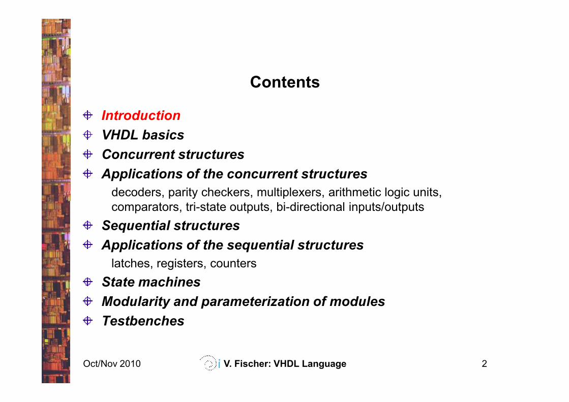
Introduction
VHDL basics
Concurrent structures
Applications of the concurrent structures
decoders, parity checkers, multiplexers, arithmetic logic units,
comparators, tri-state outputs, bi-directional inputs/outputs
Oct/Nov 2010 V. Fischer: VHDL Language 2
comparators, tri-state outputs, bi-directional inputs/outputs
Sequential structures
Applications of the sequential structures
latches, registers, counters
State machines
Modularity and parameterization of modules
Testbenches
Further reading
Digital system design with VHDL, Mark Zvolinski, Prentice Hall
VHDL Modeling for Digital Design Synthesis, Yu Chin Hsu, Kevin F.
Tsai, Jessie T. Liu, Eric S. Lin, Kluwer Academic Publishers
A guide to VHDL, Stanley Mazor, Patricia Langstraat, Kluwer Academic
Publishers
Oct/Nov 2010 V. Fischer: VHDL Language 3
Publishers
Internet Sources
http://www.2dix.com/pdf-2010/vhdl-synthesis-pdf.php
http://rdsg.epfl.ch/webdav/site/rdsg/shared/GR-SAN/vhdl-tutorial.pdf
Oct/Nov 2010 V. Fischer: VHDL Language 4
http://www.mrc.uidaho.edu/mrc/people/jff/vhdl_info/Synthesis_Art_2P.pdf
http://web.ewu.edu/groups/technology/Claudio/ee360/Lectures/vhdl-for-
synthesis.pdf
Description methods and languages
Classical description tool of the designer: schematic
diagram
• Uses logic gates or standard logic blocks
• Can contain several hierarchical levels: too complicated for
complex digital systems
Description languages – textual tools offering:
Oct/Nov 2010 V. Fischer: VHDL Language 5
Description languages – textual tools offering:
• More flexibility
• Larger variety of description techniques
First languages - PALASM, ABEL - equation-based
languages:
• Set of equations describing dependence of outputs on inputs of the
block
• Sometimes supporting state machine design, too (ABEL)
Description methods and languages (cont.)
Second generation of description languages:
• Higher-level structures enabling description of the combinatorial and
sequential systems using a behavioral approach (structures
commonly used in scientific languages)
Example: ALTERA proprietary hardware description language
(AHDL)
Oct/Nov 2010 V. Fischer: VHDL Language 6
Third generation of description languages - VHDL, Verilog
Two important evolutions:
• Technology-independent: used in multi-technology CAD systems
(notion of retargeting and transportability)
• High abstraction level is especially well adapted to the design of
complex digital systems
VHDL – VHSIC (Very High Speed Integrated Circuits) Hardware
Description Language
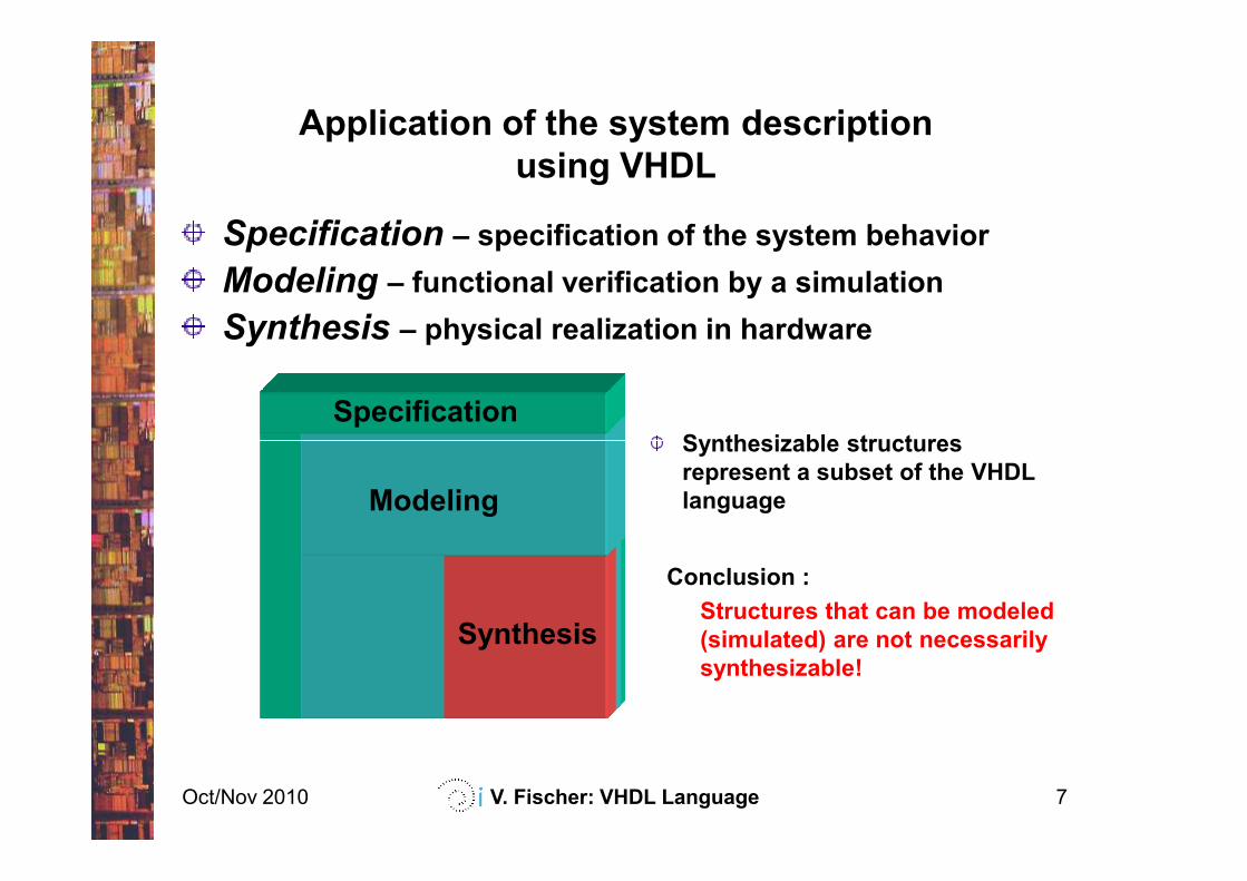
Application of the system description
using VHDL
Specification – specification of the system behavior
Modeling – functional verification by a simulation
Synthesis – physical realization in hardware
SpecificationSynthesizable structures
Oct/Nov 2010 V. Fischer: VHDL Language 7
Modeling
Synthesis
Synthesizable structures
represent a subset of the VHDL
language
Conclusion :
Structures that can be modeled
(simulated) are not necessarily
synthesizable!
Role of the simulation
With the evolution of the system complexity the design
methods have changed:
• Hardware prototyping has been gradually replaced by the
simulation - it enables to reduce the cost and the development
Oct/Nov 2010 V. Fischer: VHDL Language 8
simulation - it enables to reduce the cost and the development
delays and to design high-level digital systems
• Simulation is used in all development phases of the digital system
(specification, design and verification)
Types of simulation
Functional simulation:
• Aim – formal functional verification of each element of the system
• Signal propagation delays are not considered, the simulated
system is supposed to be perfect
Oct/Nov 2010 V. Fischer: VHDL Language 9
Timing (physical) simulation:
• Aim – to get simulation results as close to the reality (behavior of
the physical system) as possible, so
• Signal propagation delays are taken into account
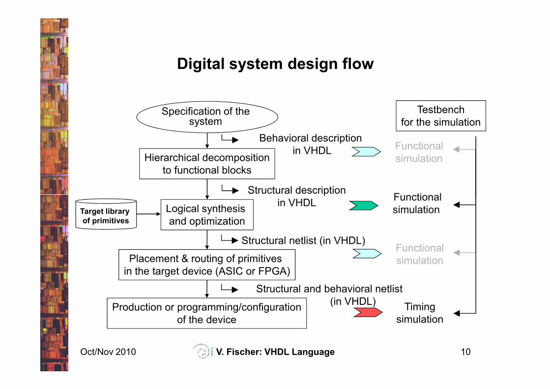
Digital system design flow
Specification of the system
Hierarchical decomposition
to functional blocks
Behavioral description
in VHDL
FunctionalStructural description
Functional
simulation
Testbench
for the simulation
Oct/Nov 2010 V. Fischer: VHDL Language 10
Logical synthesis
and optimization
Placement & routing of primitives
in the target device (ASIC or FPGA)
Production or programming/configuration
of the device
Timing
simulation
Target library
of primitives
Functional
simulation
Structural description
in VHDL
Functional
simulation
Structural netlist (in VHDL)
Structural and behavioral netlist
(in VHDL)
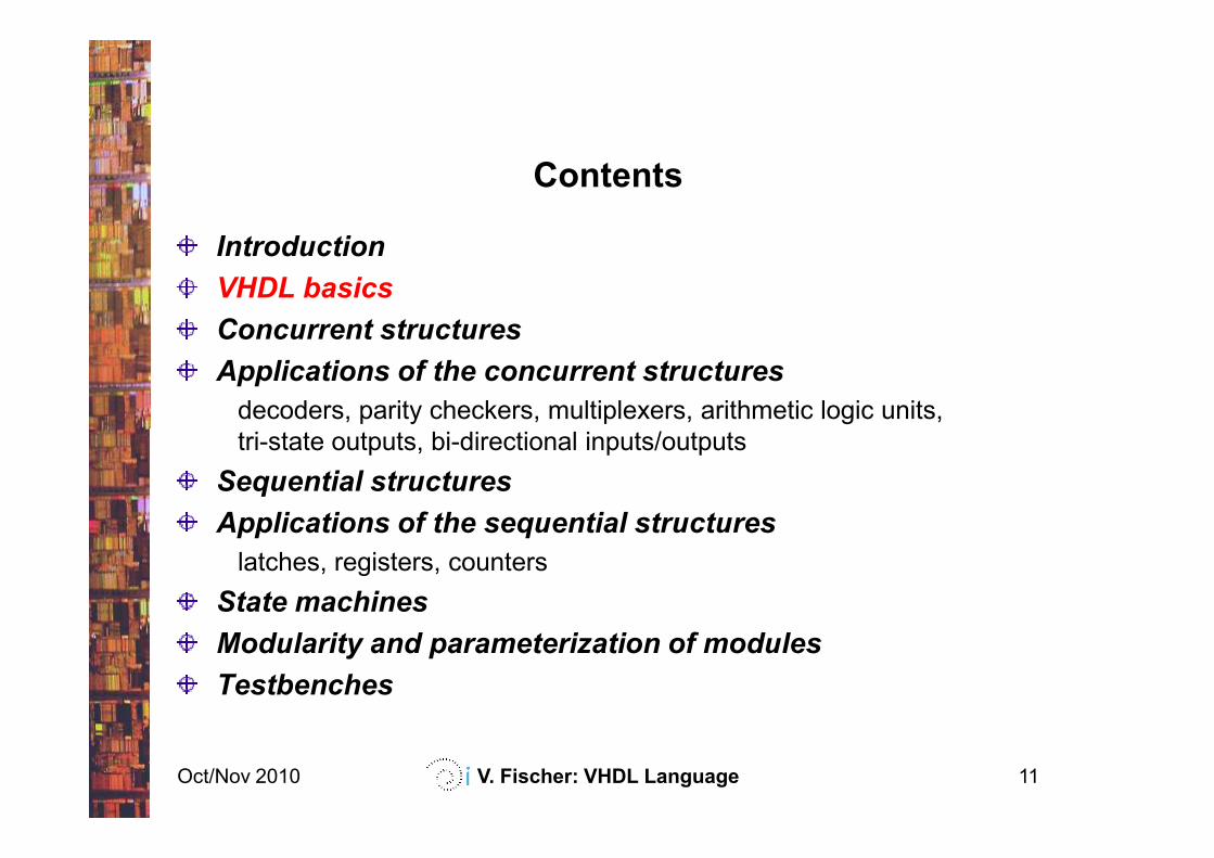
Contents
Introduction
VHDL basics
Concurrent structures
Applications of the concurrent structures
decoders, parity checkers, multiplexers, arithmetic logic units,
tri-state outputs, bi-directional inputs/outputs
Oct/Nov 2010 V. Fischer: VHDL Language 11
tri-state outputs, bi-directional inputs/outputs
Sequential structures
Applications of the sequential structures
latches, registers, counters
State machines
Modularity and parameterization of modules
Testbenches
Foreword
Characteristics of the VHDL language:
• Rich vocabulary
• Different contexts of utilization (specification, modeling, synthesis)
Two important aspects of the VHDL language:
• VHDL – a description language aimed at description/simulation of
logic systems, it is NOT a programming language
Oct/Nov 2010 V. Fischer: VHDL Language 12
logic systems, it is NOT a programming language
• Some elements of the language cannot be used in all application
contexts
Note:
In the following sections, we’ll use a subset of the VHDL language –
basic structures used to synthesize digital systems!
VHDL design units
VHDL description is composed of design units. A design unit represents
a subset of the logic structure that can be compiled separately, saved in
an independent file or in a library. It can be situated in a:
• file *.vhd (also several units in one file)
• (working) directory in several files *.vhd
• library (packet)
Design units:
Oct/Nov 2010 V. Fischer: VHDL Language 13
Design units:
• entity – basic element (component, module) defined by:
– entity specification (= external interface ⇒ symbol)
– architecture (= internal structure ⇒ schematics)
• packet – grouping of elements defined by
– packet specification– list of objects belonging to the packet
– packet body – description (definition) of each object
• configuration – association of an architecture with an entity
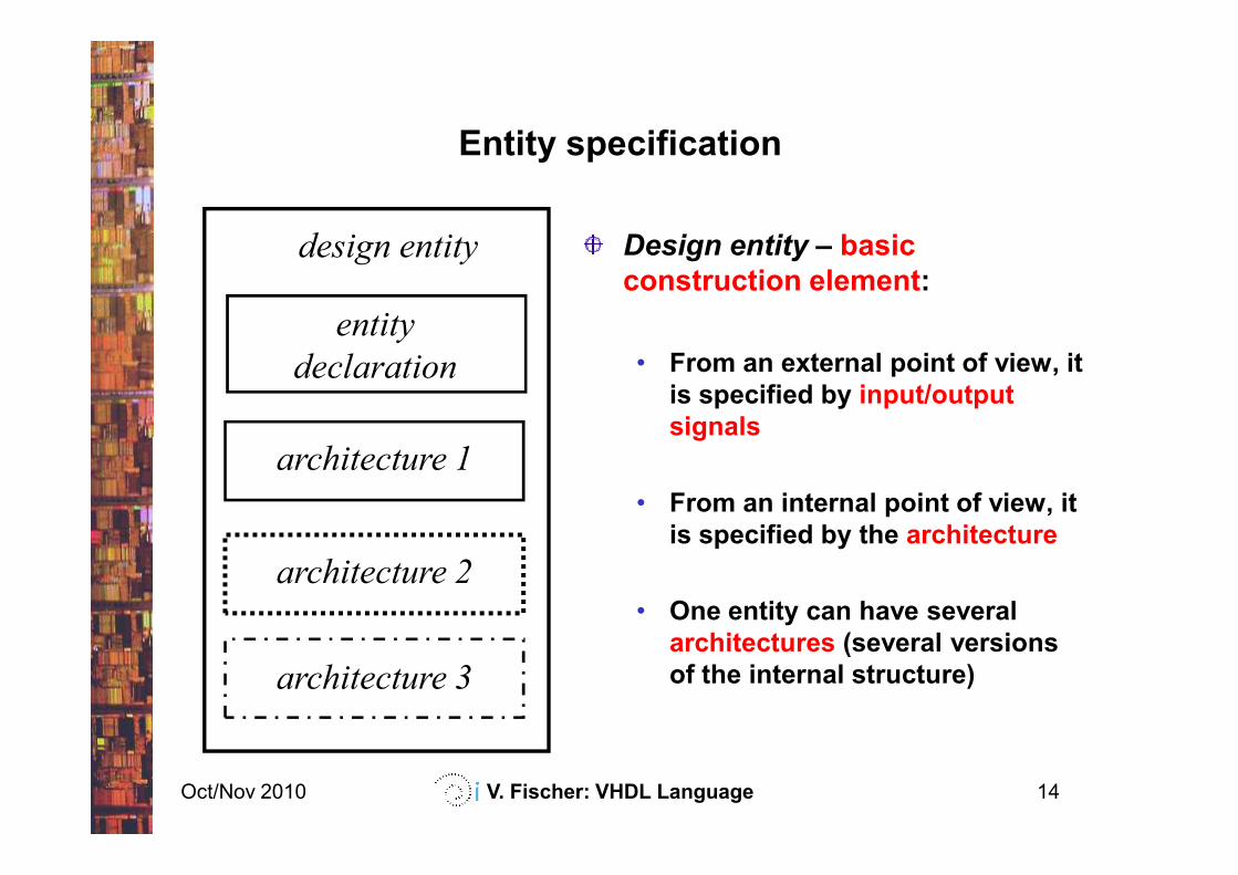
Entity specification
Design entity – basic
construction element:
• From an external point of view, it
is specified by input/output
signals
entity
declaration
design entity
Oct/Nov 2010 V. Fischer: VHDL Language 14
signals
• From an internal point of view, it
is specified by the architecture
• One entity can have several
architectures (several versions
of the internal structure)
architecture 1
architecture 2
architecture 3
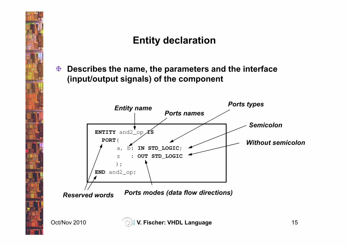
Entity declaration
Describes the name, the parameters and the interface
(input/output signals) of the component
Entity namePorts names
Ports types
Semicolon
Oct/Nov 2010 V. Fischer: VHDL Language 15
ENTITY and2_op IS
PORT(
a, b: IN STD_LOGIC;
z : OUT STD_LOGIC
);
END and2_op;
Reserved words
Semicolon
Without semicolon
Ports modes (data flow directions)
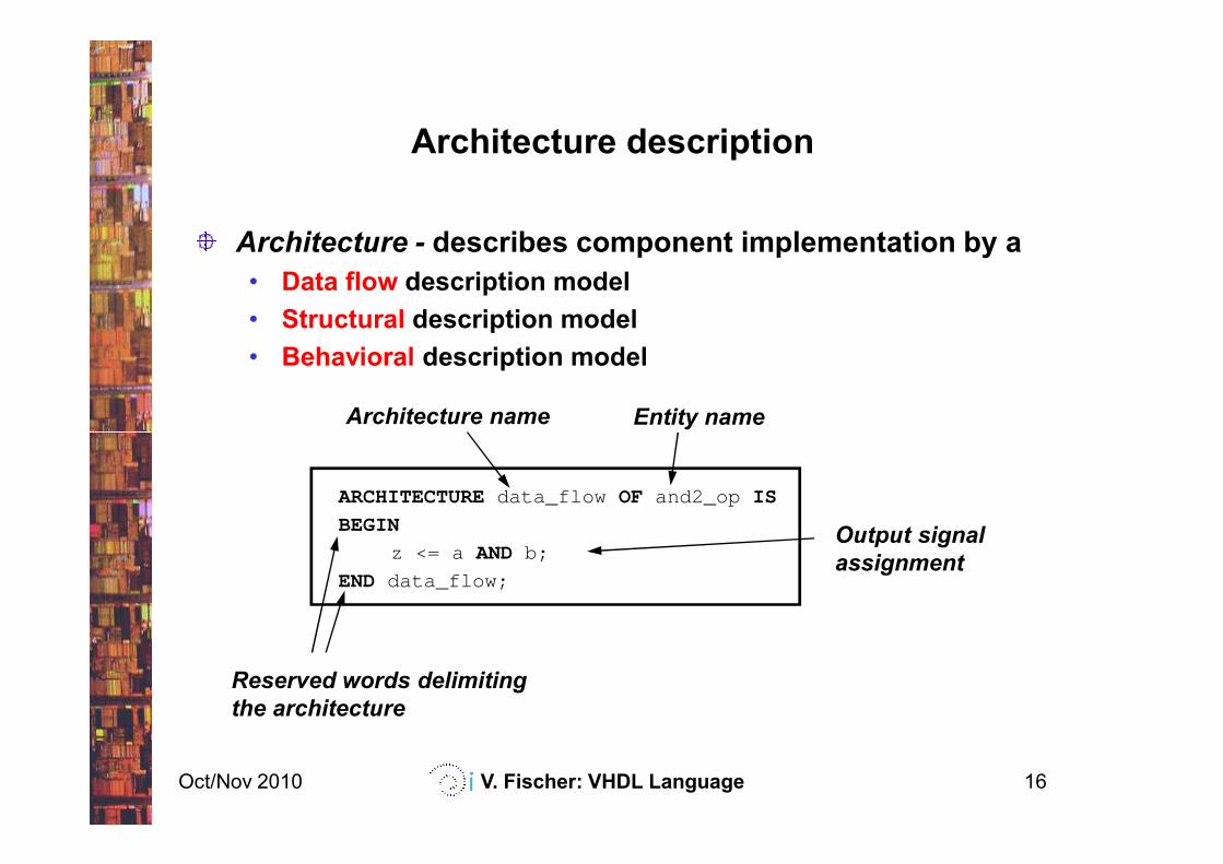
Architecture description
Architecture - describes component implementation by a
• Data flow description model
• Structural description model
• Behavioral description model
Architecture name Entity name
Oct/Nov 2010 V. Fischer: VHDL Language 16
ARCHITECTUREdata_flow OF and2_op IS
BEGIN
z <= a AND b;
END data_flow;
Reserved words delimiting
the architecture
Output signal
assignment
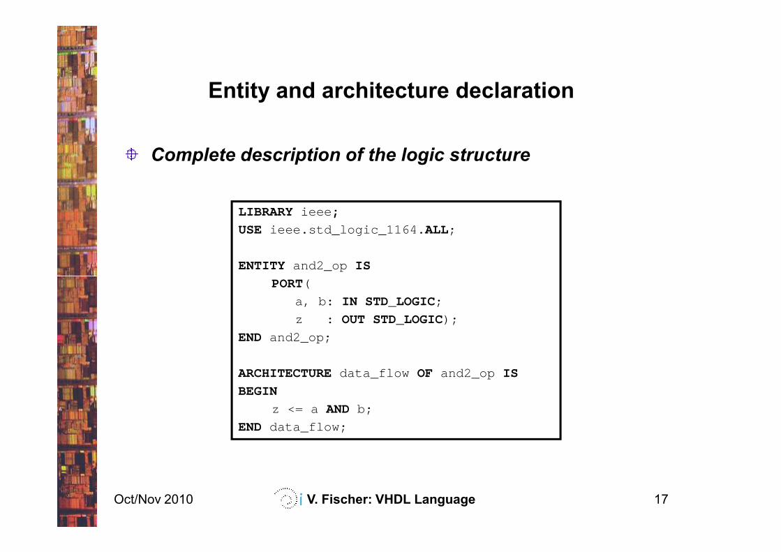
Entity and architecture declaration
Complete description of the logic structure
LIBRARY ieee ;
USE ieee.std_logic_1164. ALL;
ENTITY and2_op IS
Oct/Nov 2010 V. Fischer: VHDL Language 17
PORT(
a, b: IN STD_LOGIC;
z : OUT STD_LOGIC);
END and2_op;
ARCHITECTUREdata_flow OF and2_op IS
BEGIN
z <= a AND b;
END data_flow;
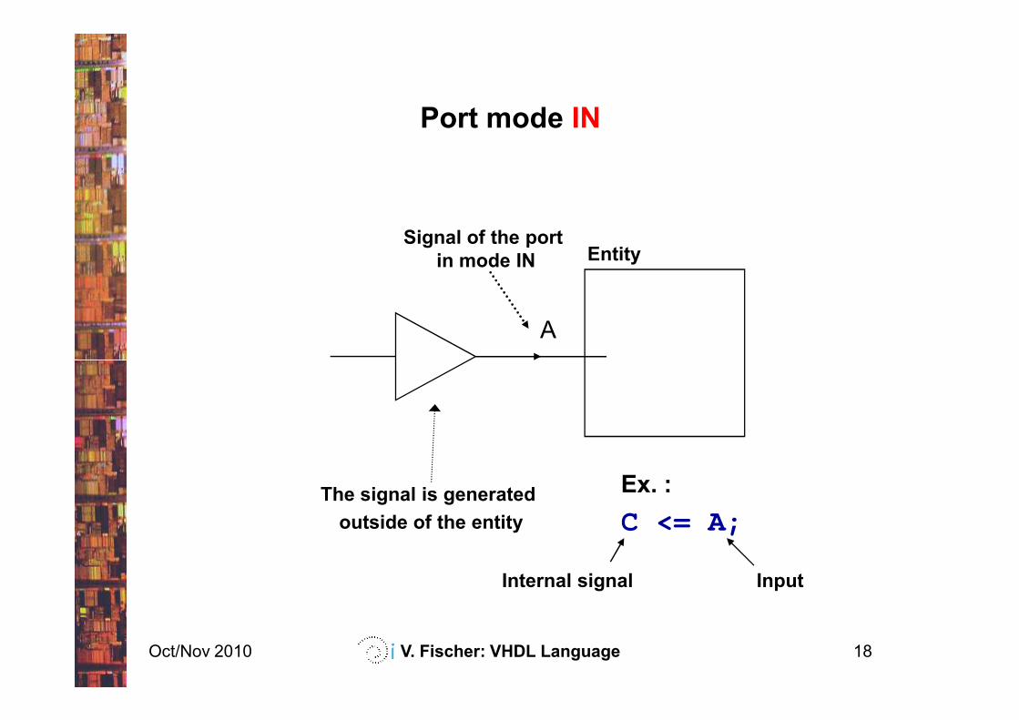
Port mode IN
A
EntitySignal of the port
in mode IN
Oct/Nov 2010 V. Fischer: VHDL Language 18
The signal is generated
outside of the entity
Ex. :
C <= A;
Internal signal Input
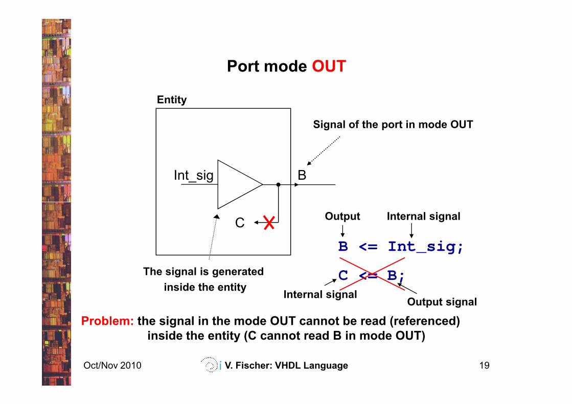
Port mode OUT
Entity
Signal of the port in mode OUT
BInt_sig
Oct/Nov 2010 V. Fischer: VHDL Language 19
The signal is generated
inside the entity
C
Problem: the signal in the mode OUT cannot be read (referenced)
inside the entity (C cannot read B in mode OUT)
C <= B;
B <= Int_sig;
Internal signalOutput
Output signalInternal signal
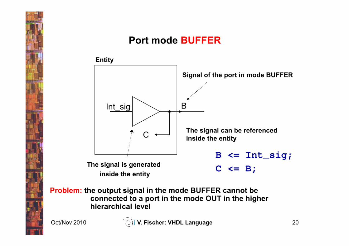
Port mode BUFFER
Entity
Signal of the port in mode BUFFER
BInt_sig
Oct/Nov 2010 V. Fischer: VHDL Language 20
The signal is generated
inside the entity
The signal can be referenced
inside the entityC
Problem: the output signal in the mode BUFFER cannot be connected to a port in the mode OUT in the higher hierarchical level
C <= B;
B <= Int_sig;
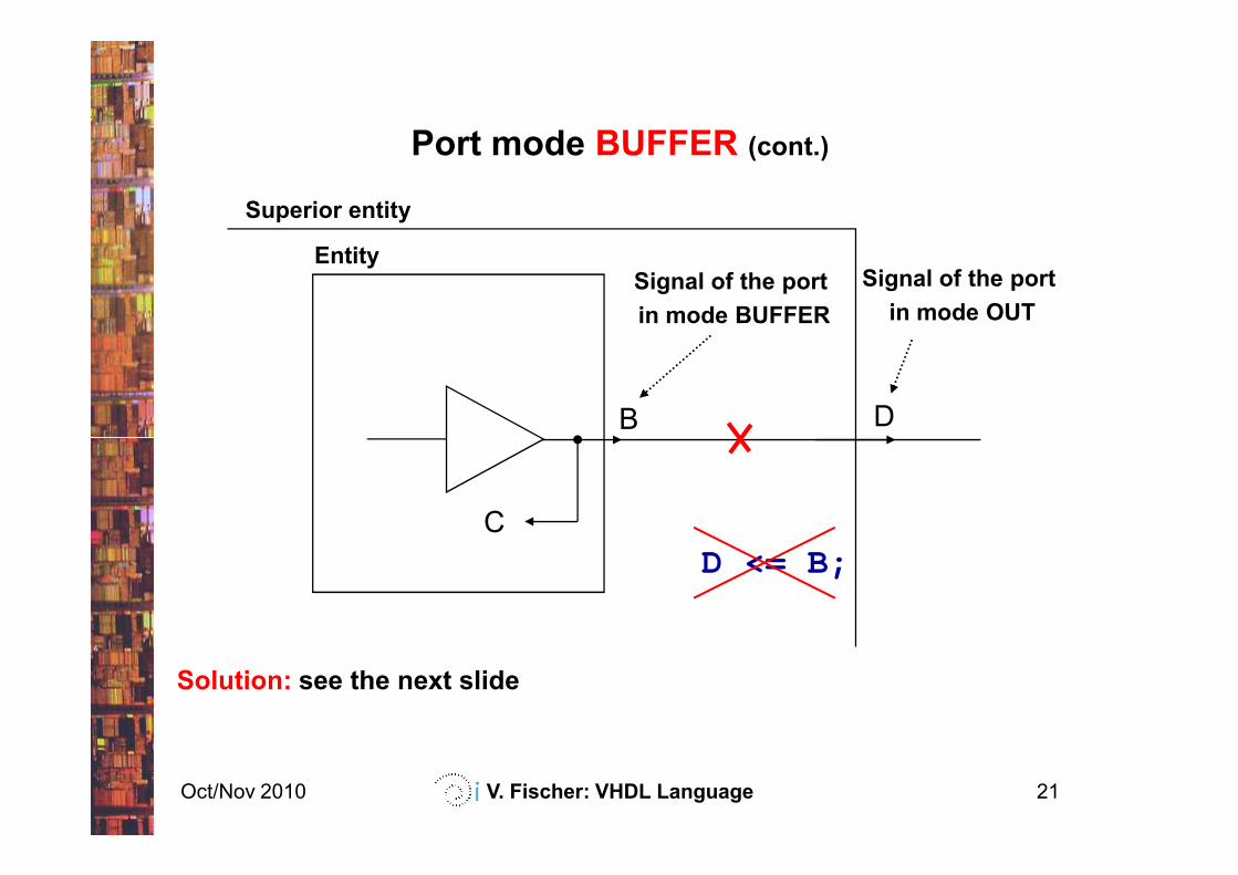
EntitySignal of the port
in mode BUFFER
B
Superior entity
D
Signal of the port
in mode OUT
Port mode BUFFER (cont.)
Oct/Nov 2010 V. Fischer: VHDL Language 21
D <= B;C
Solution: see the next slide
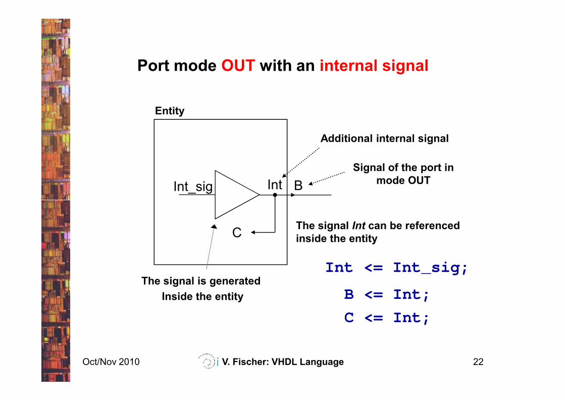
Port mode OUT with an internal signal
Entity
Signal of the port in
mode OUTBInt
Additional internal signal
Int_sig
Oct/Nov 2010 V. Fischer: VHDL Language 22
The signal is generated
Inside the entity
The signal Int can be referenced
inside the entity
B <= Int;
C <= Int;
C
Int <= Int_sig;
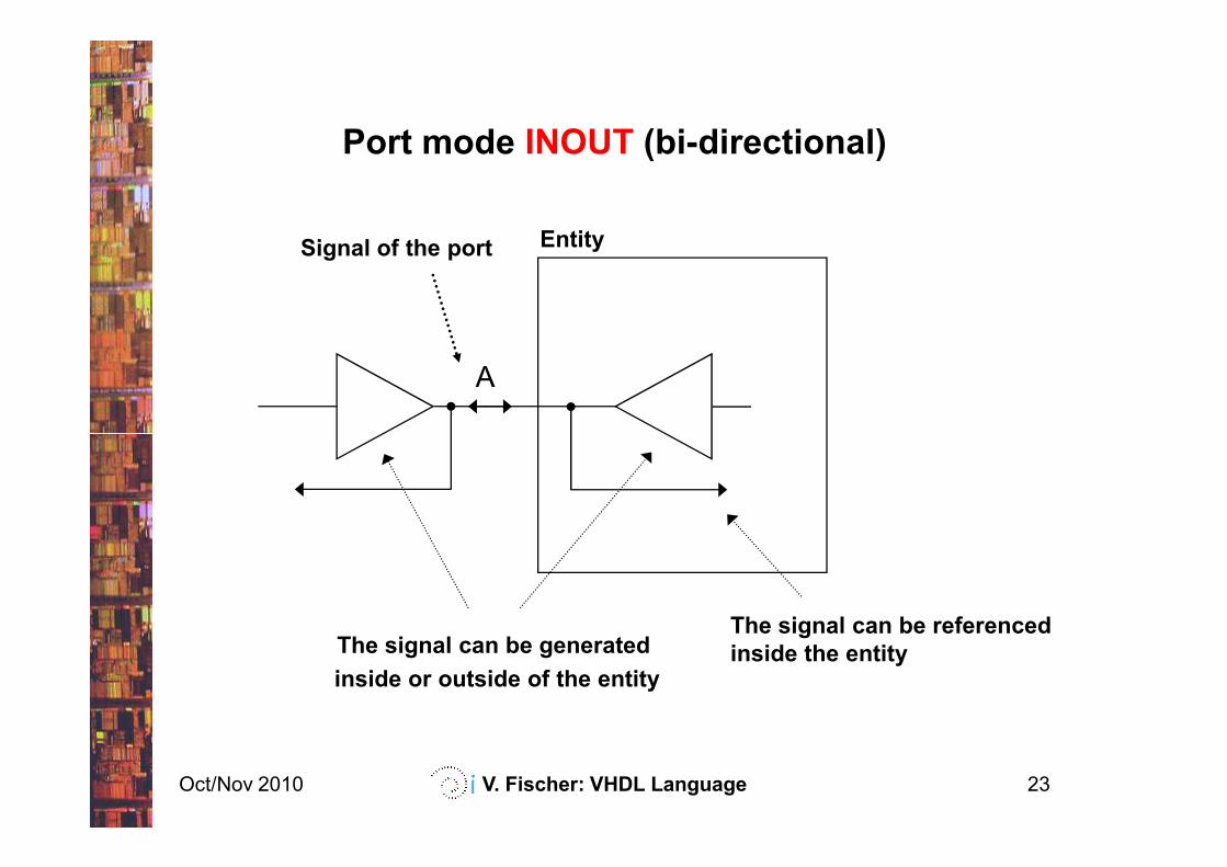
Port mode INOUT (bi-directional)
EntitySignal of the port
A
Oct/Nov 2010 V. Fischer: VHDL Language 23
The signal can be generated
inside or outside of the entity
The signal can be referenced
inside the entity
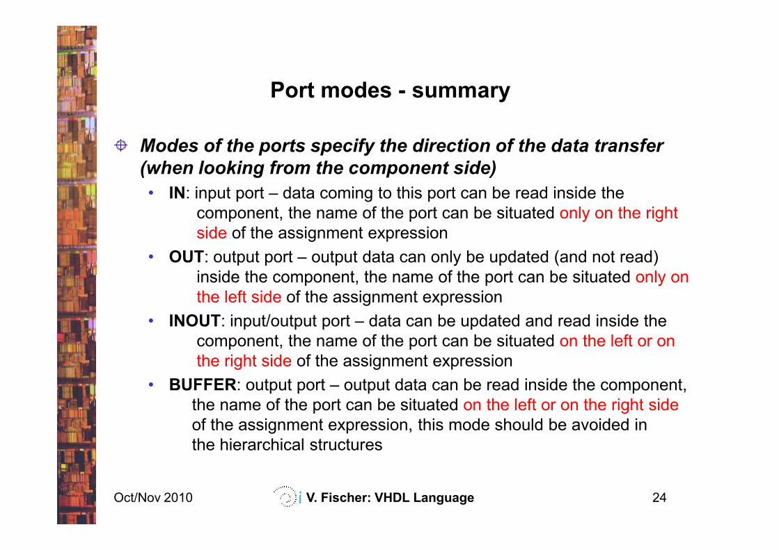
Port modes - summary
Modes of the ports specify the direction of the data transfer
(when looking from the component side)
• IN: input port – data coming to this port can be read inside the
component, the name of the port can be situated only on the right
side of the assignment expression
• OUT: output port – output data can only be updated (and not read)
inside the component, the name of the port can be situated only on
Oct/Nov 2010 V. Fischer: VHDL Language 24
inside the component, the name of the port can be situated only on
the left side of the assignment expression
• INOUT: input/output port – data can be updated and read inside the
component, the name of the port can be situated on the left or on
the right side of the assignment expression
• BUFFER: output port – output data can be read inside the component,
the name of the port can be situated on the left or on the right side
of the assignment expression, this mode should be avoided in
the hierarchical structures
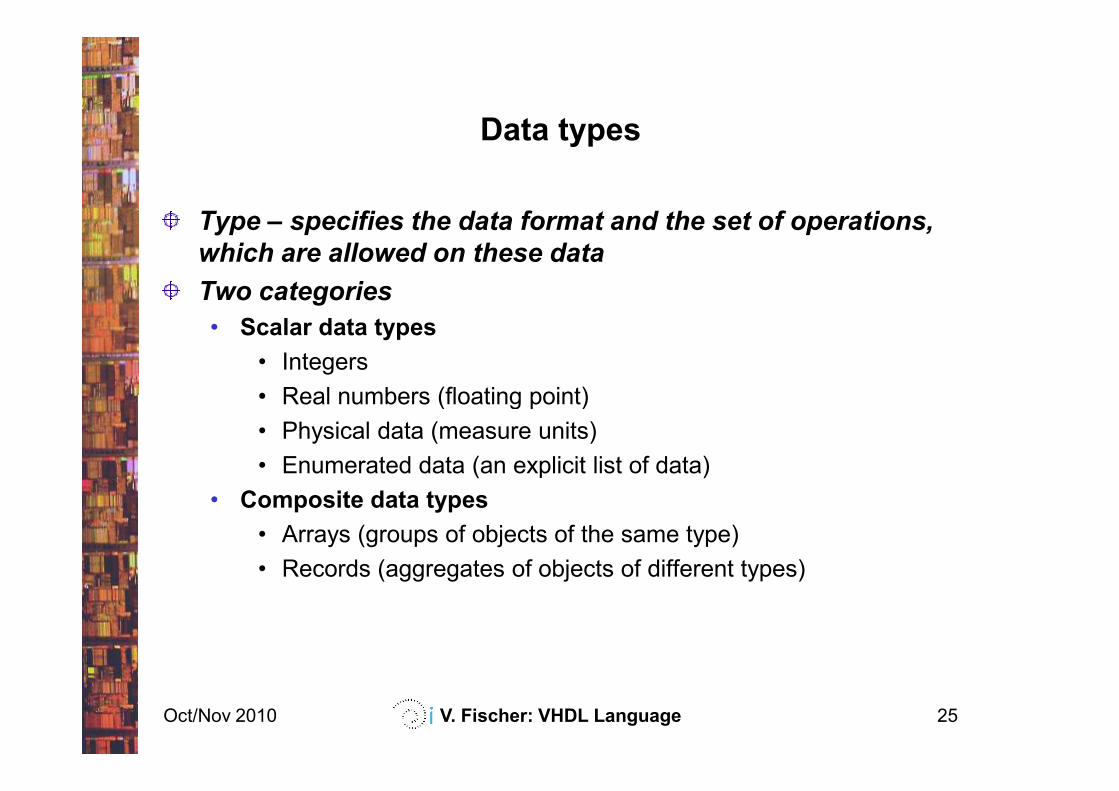
Data types
Type – specifies the data format and the set of operations,
which are allowed on these data
Two categories
• Scalar data types
• Integers
• Real numbers (floating point)
Oct/Nov 2010 V. Fischer: VHDL Language 25
• Real numbers (floating point)
• Physical data (measure units)
• Enumerated data (an explicit list of data)
• Composite data types
• Arrays (groups of objects of the same type)
• Records (aggregates of objects of different types)
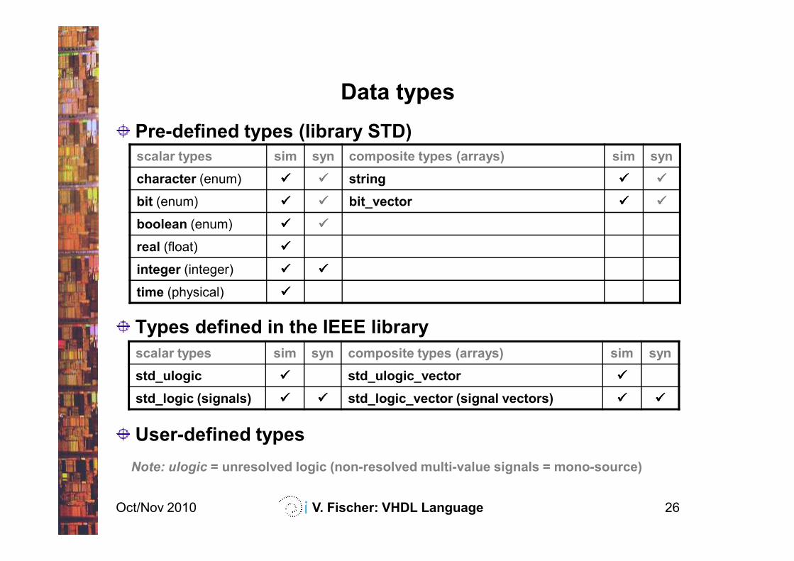
Data types
Pre-defined types (library STD)
scalar types sim syn composite types (arrays) sim syn
character (enum) ���� ���� string ���� ����
bit (enum) ���� ���� bit_vector ���� ����
boolean (enum) ���� ����
real (float) ����
integer (integer) ���� ����
Oct/Nov 2010 V. Fischer: VHDL Language 26
Types defined in the IEEE library
User-defined types
Note: ulogic = unresolved logic (non-resolved multi-value signals = mono-source)
time (physical) ����
scalar types sim syn composite types (arrays) sim syn
std_ulogic ���� std_ulogic_vector ����
std_logic (signals) ���� ���� std_logic_vector (signal vectors) ���� ����
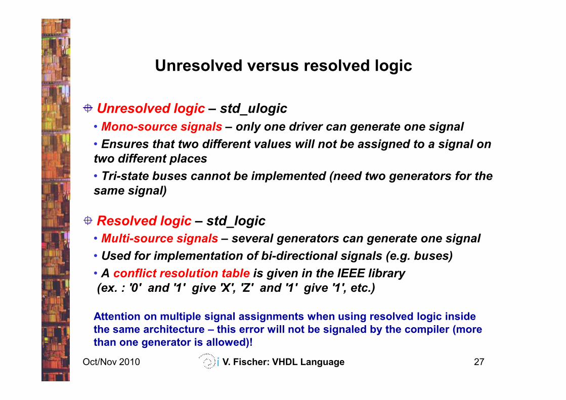
Unresolved versus resolved logic
Unresolved logic – std_ulogic
• Mono-source signals – only one driver can generate one signal
• Ensures that two different values will not be assigned to a signal on
two different places
• Tri-state buses cannot be implemented (need two generators for the
same signal)
Oct/Nov 2010 V. Fischer: VHDL Language 27
Resolved logic – std_logic
• Multi-source signals – several generators can generate one signal
• Used for implementation of bi-directional signals (e.g. buses)
• A conflict resolution table is given in the IEEE library
(ex. : '0' and '1' give 'X', 'Z' and '1' give '1', etc.)
Attention on multiple signal assignments when using resolved logic inside
the same architecture – this error will not be signaled by the compiler (more
than one generator is allowed)!
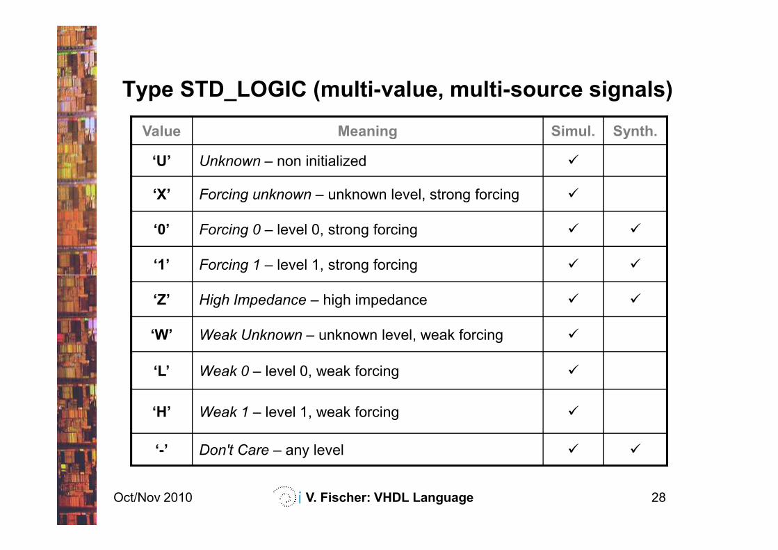
Type STD_LOGIC (multi-value, multi-source signals)
Value Meaning Simul. Synth.
‘U’ Unknown – non initialized �
‘X’ Forcing unknown – unknown level, strong forcing �
‘0’ Forcing 0 – level 0, strong forcing � �
‘1’ Forcing 1 – level 1, strong forcing � �
Oct/Nov 2010 V. Fischer: VHDL Language 28
‘Z’ High Impedance – high impedance � �
‘W’ Weak Unknown – unknown level, weak forcing �
‘L’ Weak 0 – level 0, weak forcing �
‘H’ Weak 1 – level 1, weak forcing �
‘-’ Don't Care – any level � �
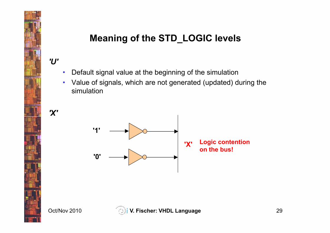
Meaning of the STD_LOGIC levels
'U'
• Default signal value at the beginning of the simulation
• Value of signals, which are not generated (updated) during the
simulation
'X'
Oct/Nov 2010 V. Fischer: VHDL Language 29
'X'
Logic contention
on the bus!
'1'
'0'
'X'
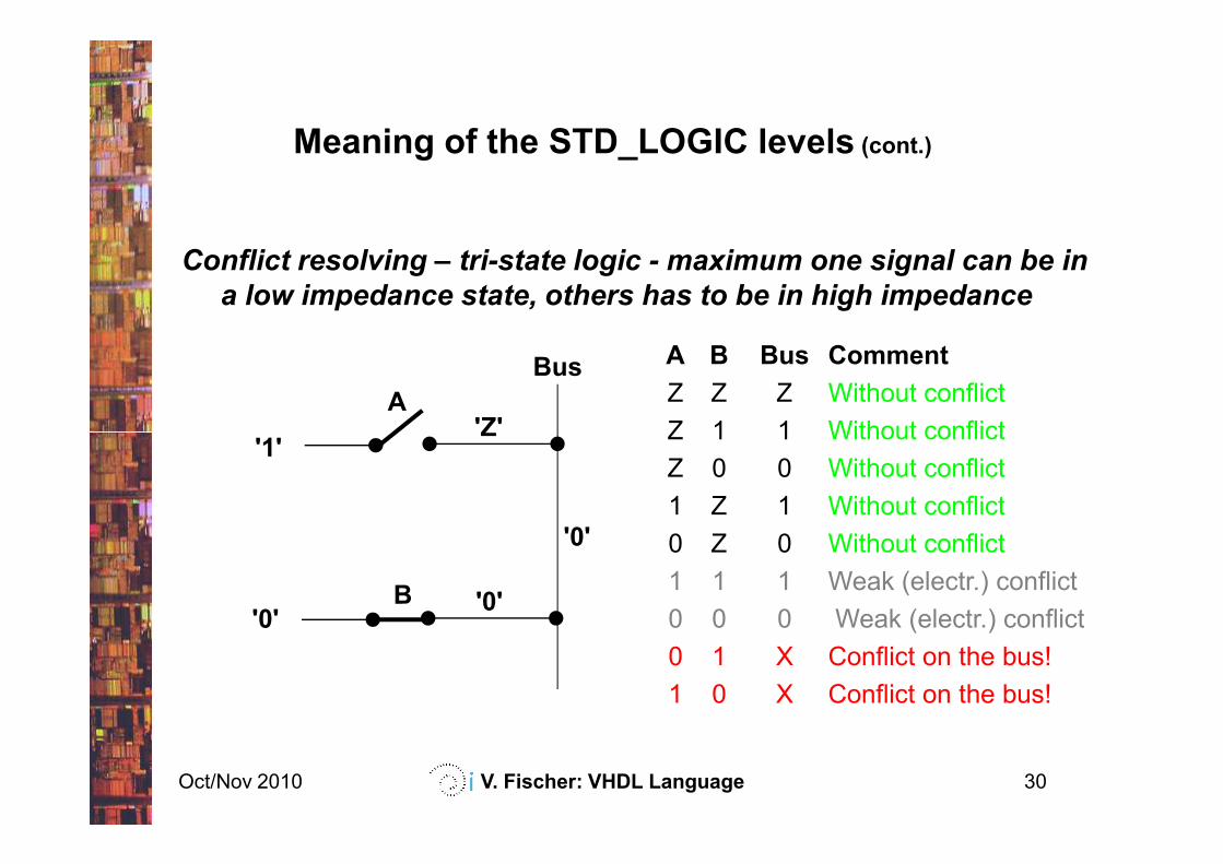
Meaning of the STD_LOGIC levels (cont.)
Conflict resolving – tri-state logic - maximum one signal can be in
a low impedance state, others has to be in high impedance
A B Bus Comment
Z Z Z Without conflict
Z 1 1 Without conflictA
'Z'
Bus
Oct/Nov 2010 V. Fischer: VHDL Language 30
B
Z 1 1 Without conflict
Z 0 0 Without conflict
1 Z 1 Without conflict
0 Z 0 Without conflict
1 1 1 Weak (electr.) conflict
0 0 0 Weak (electr.) conflict
0 1 X Conflict on the bus!
1 0 X Conflict on the bus!
'0'
'0'
'1''Z'
'0'
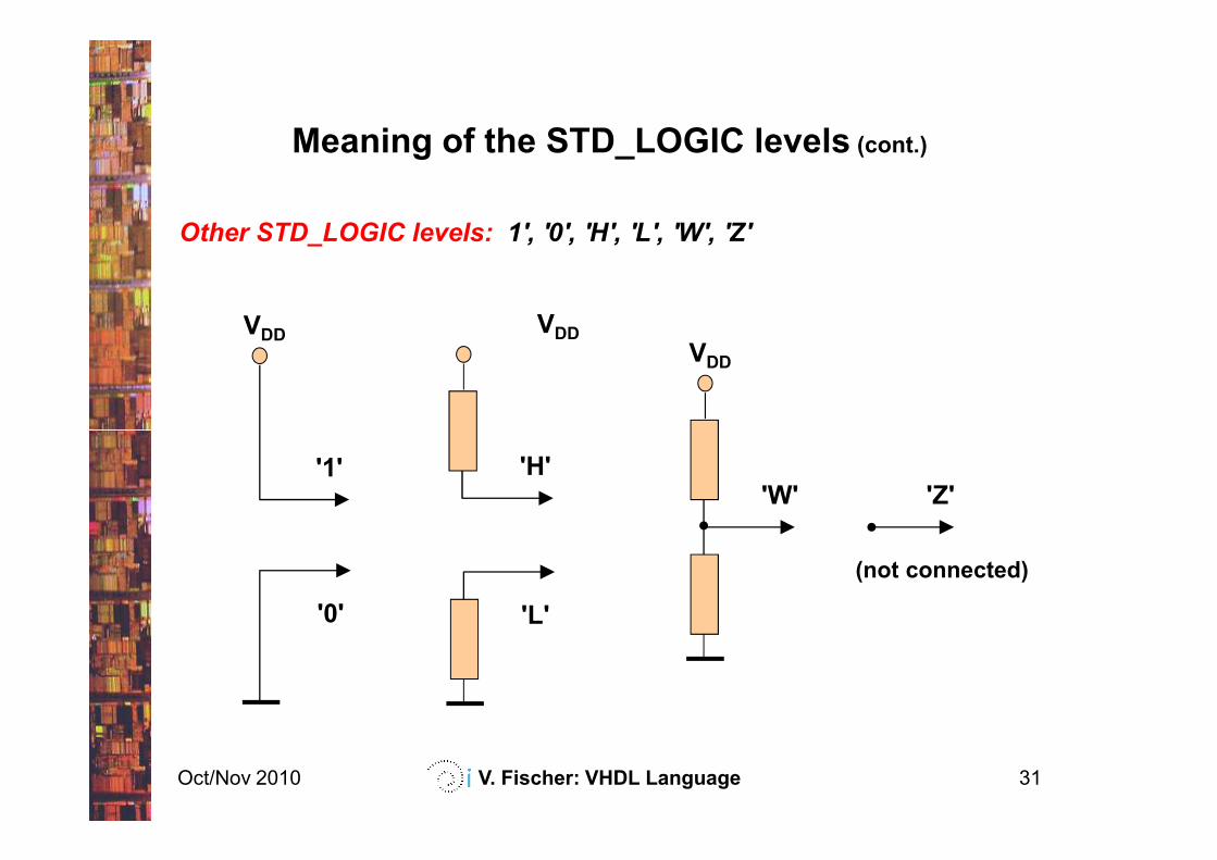
Meaning of the STD_LOGIC levels (cont.)
VDDVDD
VDD
Other STD_LOGIC levels: 1', '0', 'H', 'L', 'W', 'Z'
Oct/Nov 2010 V. Fischer: VHDL Language 31
'H'
'0'
'1'
'L'
'W' 'Z'
(not connected)
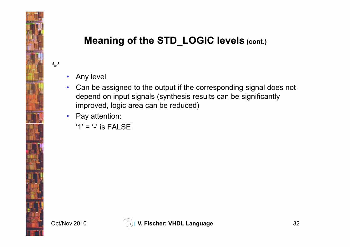
Meaning of the STD_LOGIC levels (cont.)
‘-’
• Any level
• Can be assigned to the output if the corresponding signal does not
depend on input signals (synthesis results can be significantly
improved, logic area can be reduced)
• Pay attention:
‘1’ = ‘-’ is FALSE
Oct/Nov 2010 V. Fischer: VHDL Language 32
‘1’ = ‘-’ is FALSE
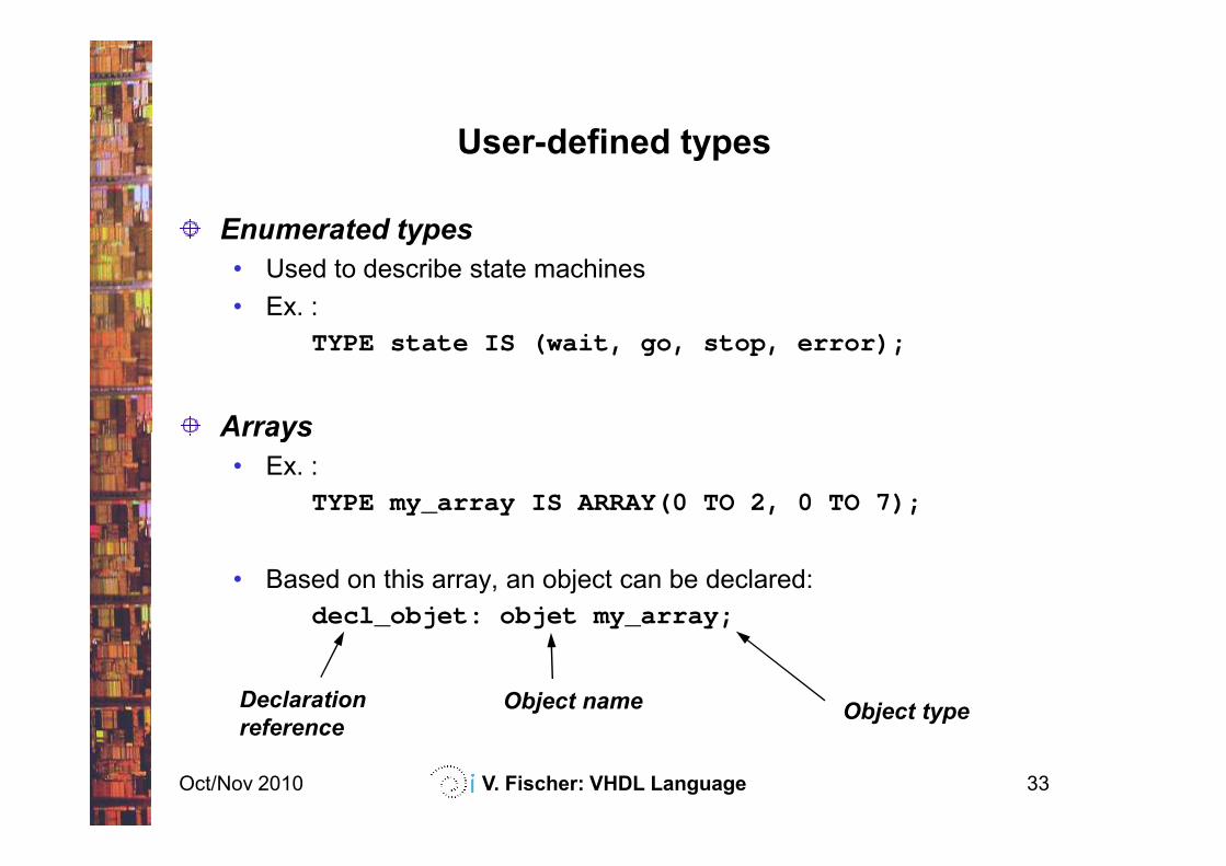
User-defined types
Enumerated types
• Used to describe state machines
• Ex. :
TYPE state IS (wait, go, stop, error);
Arrays
Oct/Nov 2010 V. Fischer: VHDL Language 33
Arrays
• Ex. :
TYPE my_array IS ARRAY(0 TO 2, 0 TO 7);
• Based on this array, an object can be declared:
decl_objet: objet my_array;
Object typeObject nameDeclaration
reference
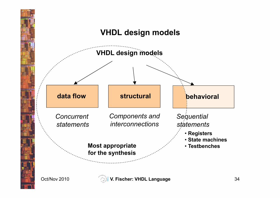
VHDL design models
structural
VHDL design models
data flow behavioral
Oct/Nov 2010 V. Fischer: VHDL Language 34
Components and
interconnections
structuraldata flow
Concurrent
statements
• Registers
• State machines
• Testbenches
Sequential
statements
Most appropriate
for the synthesis
behavioral
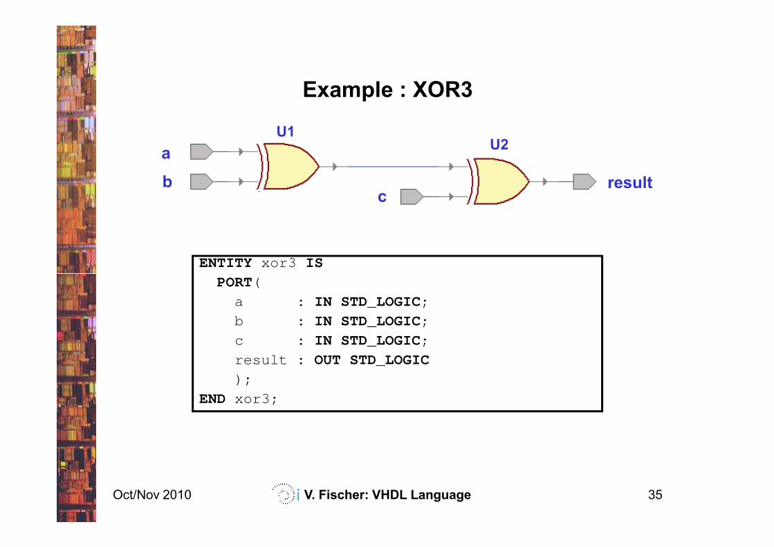
Example : XOR3
a
bc
result
ENTITY xor3 IS
U1U2
Oct/Nov 2010 V. Fischer: VHDL Language 35
PORT(
a : IN STD_LOGIC;
b : IN STD_LOGIC;
c : IN STD_LOGIC;
result : OUT STD_LOGIC
);
END xor3;
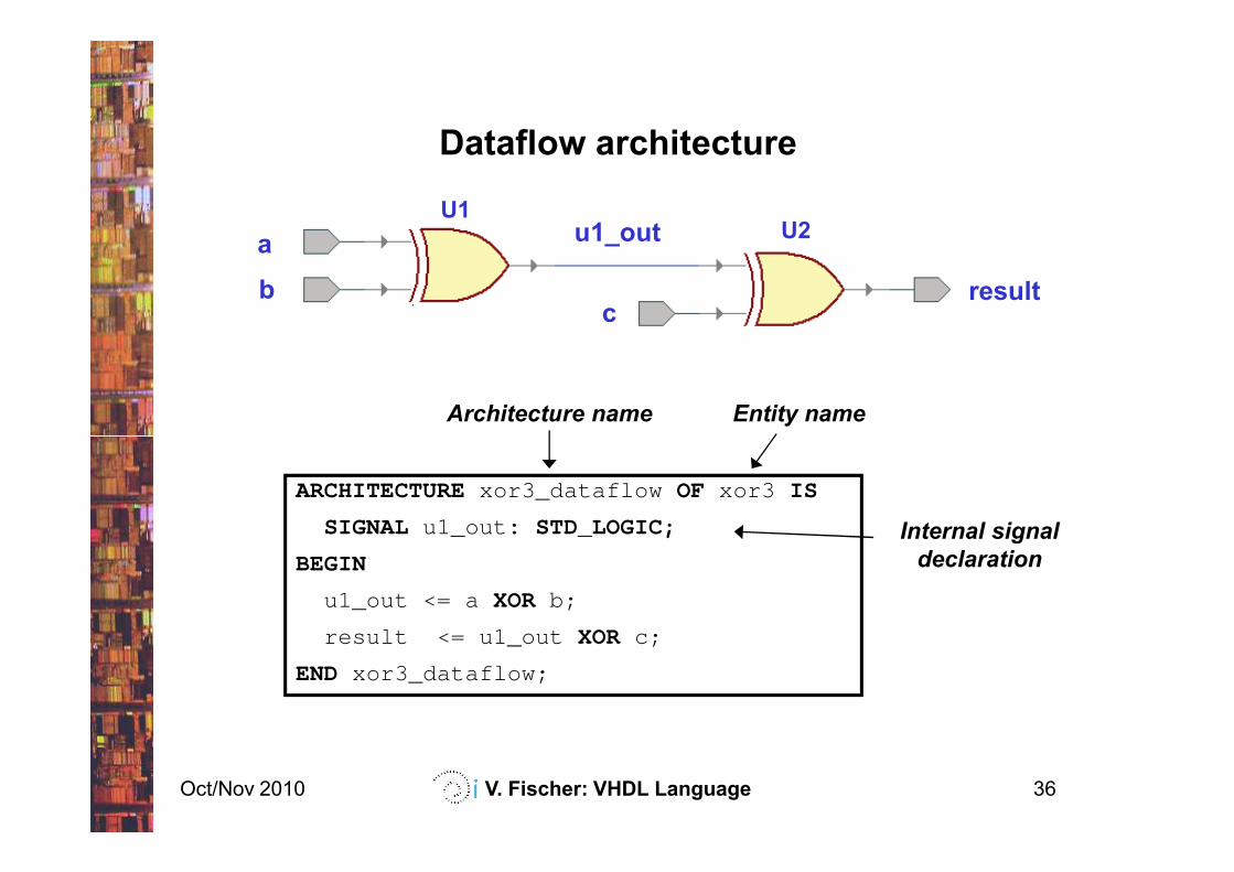
Dataflow architecture
a
bc
result
u1_out
Architecture name Entity name
U1U2
Oct/Nov 2010 V. Fischer: VHDL Language 36
ARCHITECTURExor3_dataflow OF xor3 IS
SIGNAL u1_out : STD_LOGIC;
BEGIN
u1_out <= a XOR b;
result <= u1_out XOR c;
END xor3_dataflow;
Internal signal
declaration
Dataflow architecture (cont.)
Dataflow model describes relations between data inside the
module.
It uses concurrent statements to realize the logic.
Statements are evaluated simultaneously (in parallel), their
order is therefore not important!
Oct/Nov 2010 V. Fischer: VHDL Language 37
order is therefore not important!
It is the most useful, if the logic can be represented using
Boolean statements (combinatorial logic).
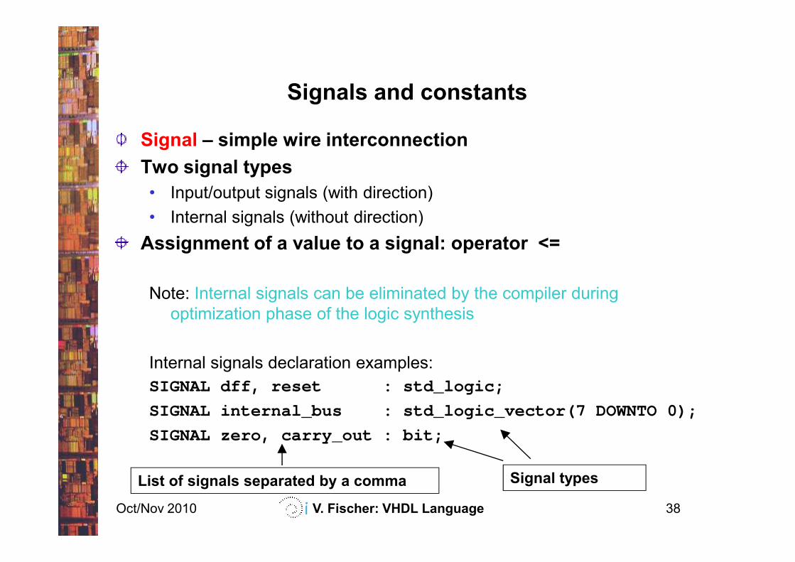
Signals and constants
Signal – simple wire interconnection
Two signal types
• Input/output signals (with direction)
• Internal signals (without direction)
Assignment of a value to a signal: operator <=
Oct/Nov 2010 V. Fischer: VHDL Language 38
Note: Internal signals can be eliminated by the compiler during
optimization phase of the logic synthesis
Internal signals declaration examples:
SIGNAL dff, reset : std_logic;
SIGNAL internal_bus : std_logic_vector(7 DOWNTO 0);
SIGNAL zero, carry_out : bit;
List of signals separated by a comma Signal types
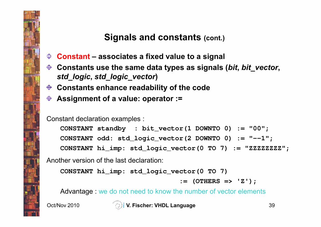
Signals and constants (cont.)
Constant – associates a fixed value to a signal
Constants use the same data types as signals (bit, bit_vector,
std_logic, std_logic_vector)
Constants enhance readability of the code
Assignment of a value: operator :=
Oct/Nov 2010 V. Fischer: VHDL Language 39
Constant declaration examples :
CONSTANT standby : bit_vector(1 DOWNTO 0) := "00";
CONSTANT odd: std_logic_vector(2 DOWNTO 0) := "--1";
CONSTANT hi_imp: std_logic_vector(0 TO 7) := "ZZZZZZZZ";
Another version of the last declaration:
CONSTANT hi_imp: std_logic_vector(0 TO 7)
:= (OTHERS => 'Z');
Advantage : we do not need to know the number of vector elements
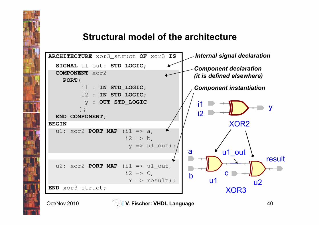
Structural model of the architecture
i1
i2y
Component declaration
(it is defined elsewhere)
Component instantiation
ARCHITECTURExor3_struct OF xor3 IS
SIGNAL u1_out : STD_LOGIC;COMPONENT xor2
PORT(i1 : IN STD_LOGIC;i2 : IN STD_LOGIC;
y : OUT STD_LOGIC);
Internal signal declaration
Oct/Nov 2010 V. Fischer: VHDL Language 40
i2
XOR2
XOR3
resultu1_outa
b cu1 u2
);END COMPONENT;
BEGINu1: xor2 PORT MAP (i1 => a,
i2 => b,y => u1_out);
u2: xor2 PORT MAP (i1 => u1_out,i2 => C,
Y => result);END xor3_struct;
Structural model of the architecture (cont.)
It is easy to understand. It is close to schematics design: it
uses simple blocks to create higher-level logic functions
Components can be interconnected in a hierarchical
manner
In the structural model we can connect simple logic ports or
Oct/Nov 2010 V. Fischer: VHDL Language 41
In the structural model we can connect simple logic ports or
complex (and abstract) components
The structural model of the architecture is useful if the
blocks can be interconnected in a natural way
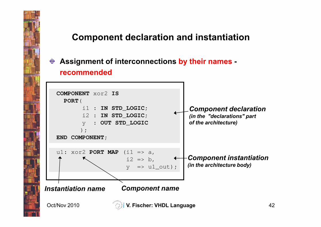
Component declaration and instantiation
COMPONENT xor2 ISPORT(
i1 : IN STD_LOGIC;i2 : IN STD_LOGIC;
Assignment of interconnections by their names -
recommended
Component declaration(in the "declarations" part
Oct/Nov 2010 V. Fischer: VHDL Language 42
i2 : IN STD_LOGIC;y : OUT STD_LOGIC
);END COMPONENT;
u1: xor2 PORT MAP (i1 => a,i2 => b,y => u1_out);
Component instantiation(in the architecture body)
(in the "declarations" part
of the architecture)
Instantiation name Component name

Component declaration and instantiation (cont.)
COMPONENT xor2 ISPORT(
i1 : IN STD_LOGIC;i2 : IN STD_LOGIC;
Assignment of connections by their position -
not recommended!
Oct/Nov 2010 V. Fischer: VHDL Language 43
i2 : IN STD_LOGIC;y : OUT STD_LOGIC
);END COMPONENT;
u1: xor2 PORT MAP (a, b, u1_out);
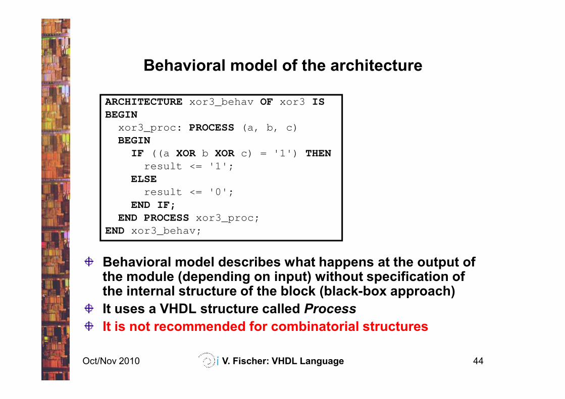
Behavioral model of the architecture
ARCHITECTURExor3_behav OF xor3 ISBEGIN
xor3_proc: PROCESS (a, b, c)BEGIN
IF ((a XOR b XOR c) = '1') THENresult <= '1';
ELSEresult <= '0';
END IF;
Oct/Nov 2010 V. Fischer: VHDL Language 44
END IF;END PROCESSxor3_proc;
END xor3_behav;
Behavioral model describes what happens at the output of the module (depending on input) without specification of the internal structure of the block (black-box approach)
It uses a VHDL structure called Process
It is not recommended for combinatorial structures
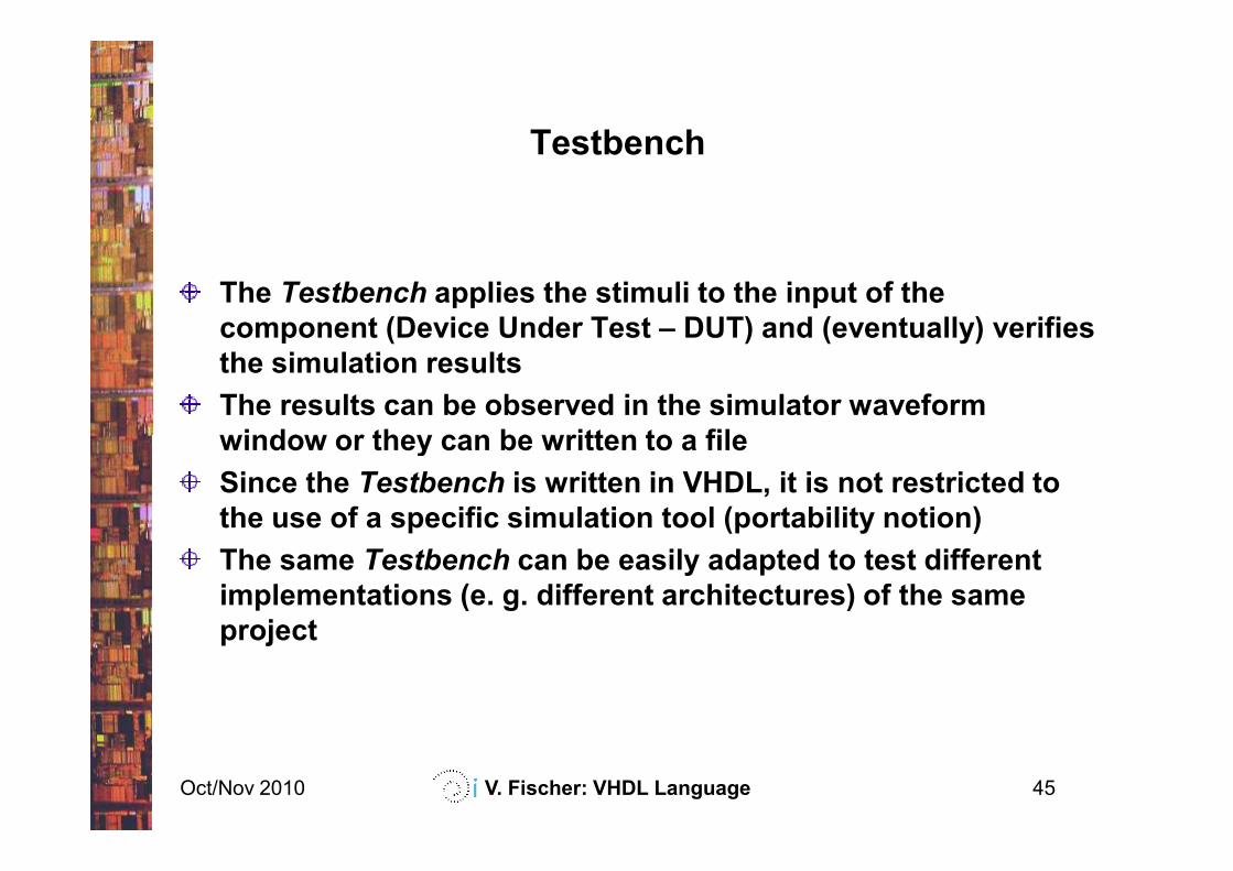
Testbench
The Testbench applies the stimuli to the input of the
component (Device Under Test – DUT) and (eventually) verifies
the simulation results
The results can be observed in the simulator waveform
window or they can be written to a file
Oct/Nov 2010 V. Fischer: VHDL Language 45
window or they can be written to a file
Since the Testbench is written in VHDL, it is not restricted to
the use of a specific simulation tool (portability notion)
The same Testbench can be easily adapted to test different
implementations (e. g. different architectures) of the same
project
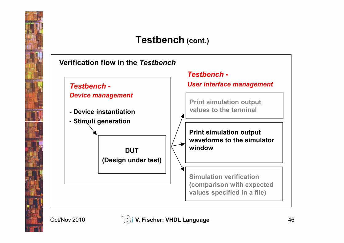
Testbench (cont.)
Testbench -
Device management
- Device instantiation
- Stimuli generation
Verification flow in the Testbench
Testbench -
User interface management
Print simulation output
values to the terminal
Oct/Nov 2010 V. Fischer: VHDL Language 46
- Stimuli generation
DUT
(Design under test)
Print simulation output
waveforms to the simulator
window
Simulation verification
(comparison with expected
values specified in a file)
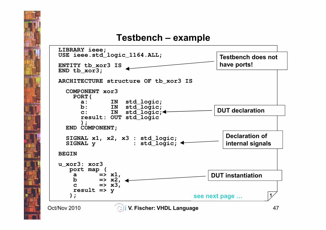
Testbench – exampleLIBRARY ieee;USE ieee.std_logic_1164.ALL;
ENTITY tb_xor3 ISEND tb_xor3;
ARCHITECTURE structure OF tb_xor3 IS
COMPONENT xor3PORT(
a: IN std_logic;b: IN std_logic;c: IN std_logic;result: OUT std_logic
Testbench does not
have ports!
DUT declaration
Oct/Nov 2010 V. Fischer: VHDL Language 47
c: IN std_logic;result: OUT std_logic);
END COMPONENT;
SIGNAL x1, x2, x3 : std_logic;SIGNAL y : std_logic;
BEGIN
u_xor3: xor3port map (
a => x1,b => x2,c => x3,result => y
); 1
Declaration of
internal signals
DUT instantiation
see next page F
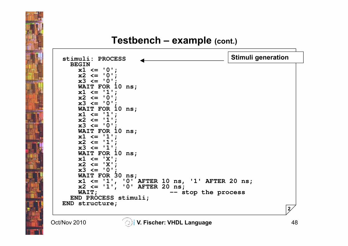
Testbench – example (cont.)
stimuli: PROCESSBEGIN
x1 <= '0';x2 <= '0';x3 <= '0';WAIT FOR 10 ns;x1 <= '1';x2 <= '0';x3 <= '0';WAIT FOR 10 ns;x1 <= '1';x2 <= '1';x3 <= '0';
Stimuli generation
Oct/Nov 2010 V. Fischer: VHDL Language 48
x2 <= '1';x3 <= '0';WAIT FOR 10 ns;x1 <= '1';x2 <= '1';x3 <= '1'; WAIT FOR 10 ns;x1 <= 'X';x2 <= 'X';x3 <= '0';WAIT FOR 30 ns;x1 <= '1', '0' AFTER 10 ns, '1' AFTER 20 ns;x2 <= '1', '0' AFTER 20 ns;WAIT; -- stop the process
END PROCESS stimuli;END structure;
2
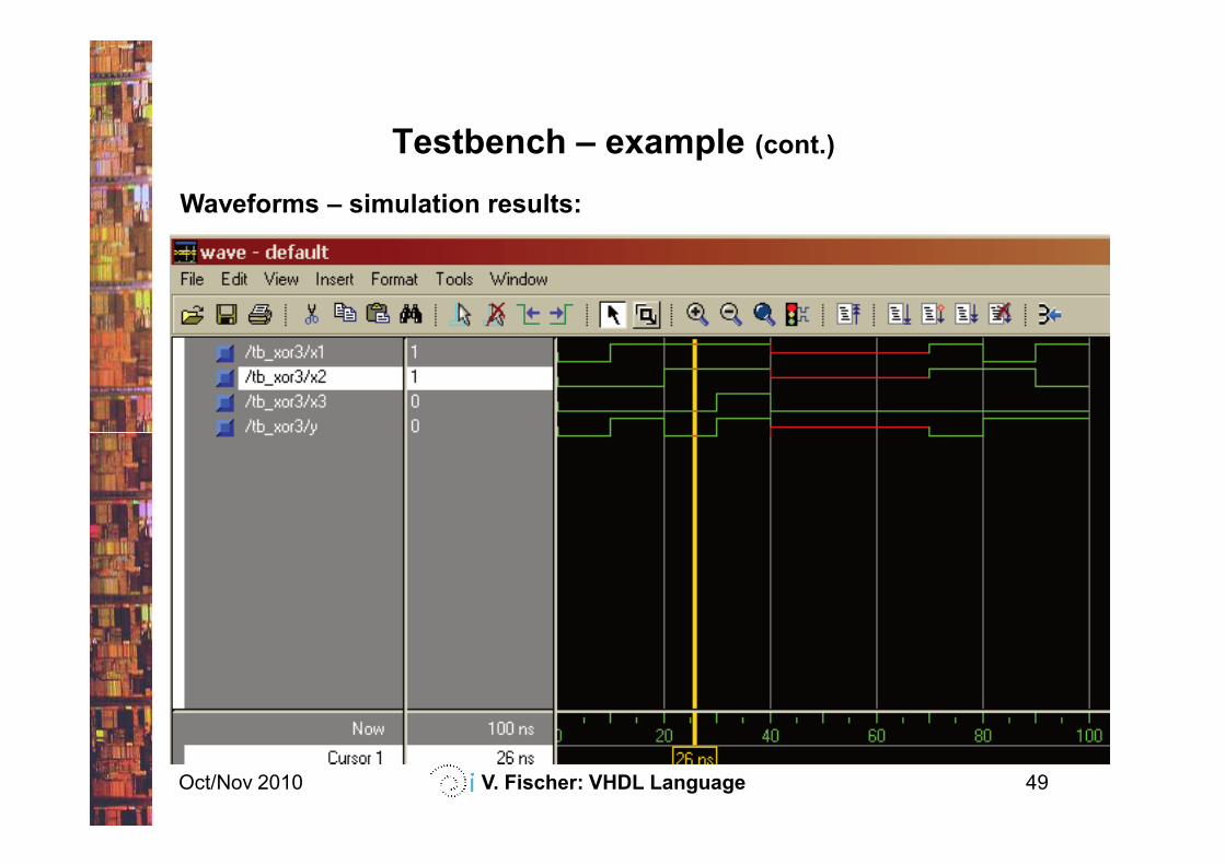
Testbench – example (cont.)
Waveforms – simulation results:
Oct/Nov 2010 V. Fischer: VHDL Language 49
Contents
Introduction
VHDL basics
Concurrent structures
Applications of the concurrent structures
decoders, parity checkers, multiplexers, arithmetic logic units,
tri-state outputs, bi-directional inputs/outputs
Oct/Nov 2010 V. Fischer: VHDL Language 50
tri-state outputs, bi-directional inputs/outputs
Sequential structures
Applications of the sequential structures
latches, registers, counters
State machines
Modularity and parameterization of modules
Testbenches
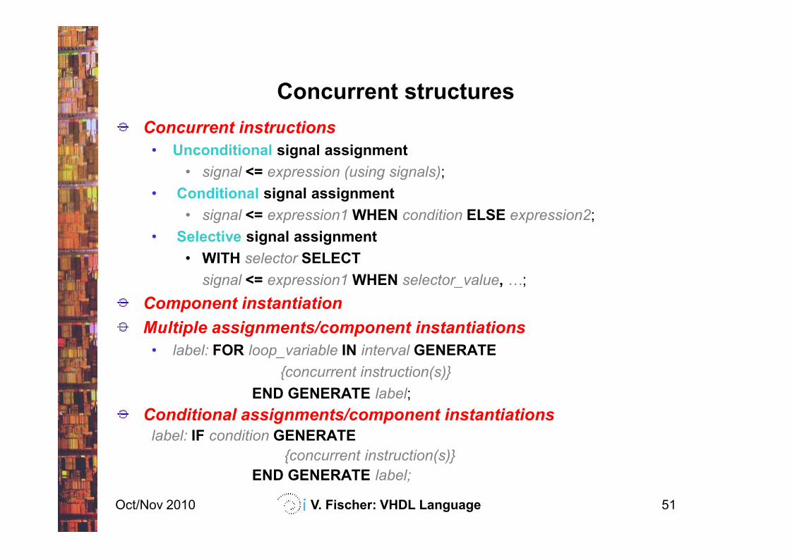
Concurrent structures
Concurrent instructions
• Unconditional signal assignment
• signal <= expression (using signals);
• Conditional signal assignment
• signal <= expression1 WHEN condition ELSE expression2;
• Selective signal assignment
• WITH selector SELECT
signal <= expression1 WHEN selector_value, -;
Oct/Nov 2010 V. Fischer: VHDL Language 51
signal <= expression1 WHEN selector_value, -;
Component instantiation
Multiple assignments/component instantiations
• label: FOR loop_variable IN interval GENERATE
{concurrent instruction(s)}
END GENERATE label;
Conditional assignments/component instantiations
label: IF condition GENERATE
{concurrent instruction(s)}
END GENERATE label;
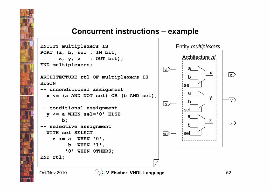
Concurrent instructions – example
ENTITY multiplexers ISPORT (a, b, sel : IN bit;
x, y, z : OUT bit);END multiplexers;
ARCHITECTURE rtl OF multiplexers ISBEGIN-- unconditional assignment
x <= (a AND NOT sel) OR (b AND sel);
Architecture rtl
a
b
sel
x
ay
a
x
Entity multiplexers
Oct/Nov 2010 V. Fischer: VHDL Language 52
x <= (a AND NOT sel) OR (b AND sel);
-- conditional assignmenty <= a WHEN sel='0' ELSE
b;-- selective assignment
WITH sel SELECTz <= a WHEN '0',
b WHEN '1','0' WHEN OTHERS;
END rtl;
a
b
sel
y
a
b
sel
z
b
sel
y
z
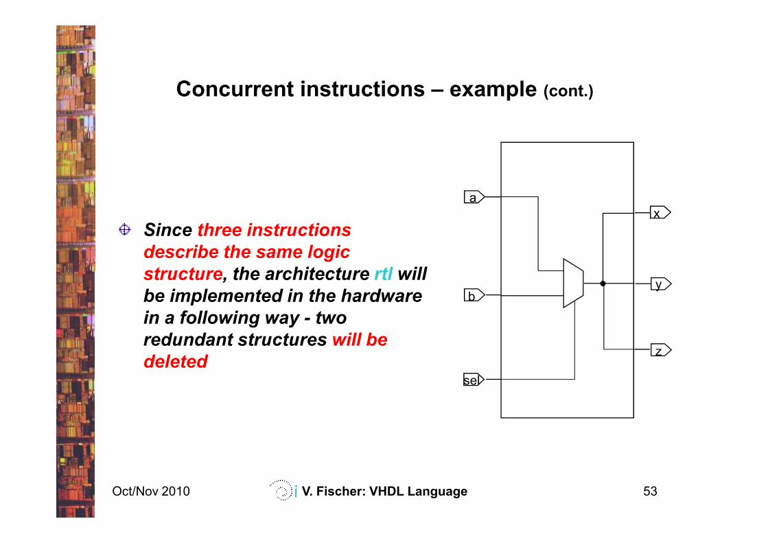
Concurrent instructions – example (cont.)
a
x
Since three instructions
describe the same logic
structure, the architecture rtl will
Oct/Nov 2010 V. Fischer: VHDL Language 53
b
sel
y
z
structure, the architecture rtl will
be implemented in the hardware
in a following way - two
redundant structures will be
deleted
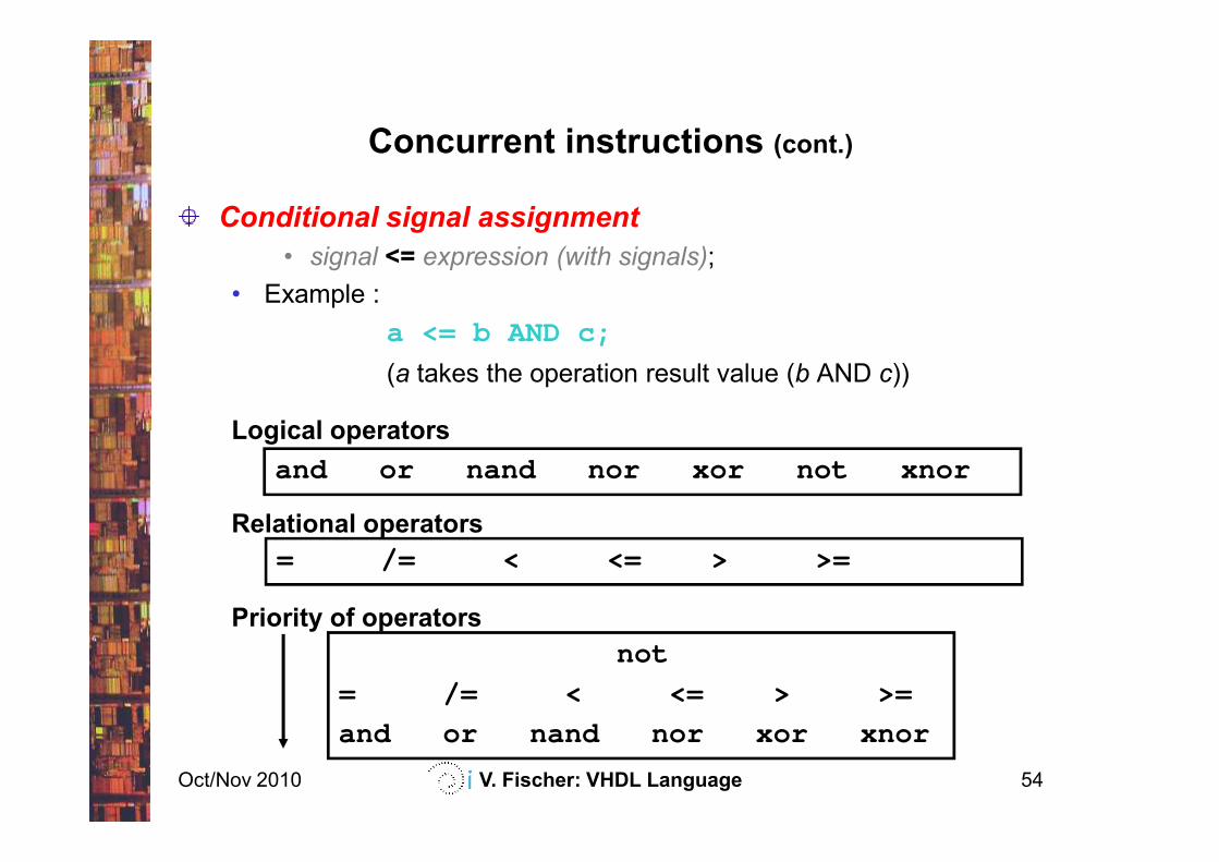
Concurrent instructions (cont.)
Conditional signal assignment
• signal <= expression (with signals);
• Example :
a <= b AND c;
(a takes the operation result value (b AND c))
Logical operators
Oct/Nov 2010 V. Fischer: VHDL Language 54
Logical operators
Relational operators
Priority of operators
and or nand nor xor not xnor
= /= < <= > >=
not
= /= < <= > >=
and or nand nor xor xnor
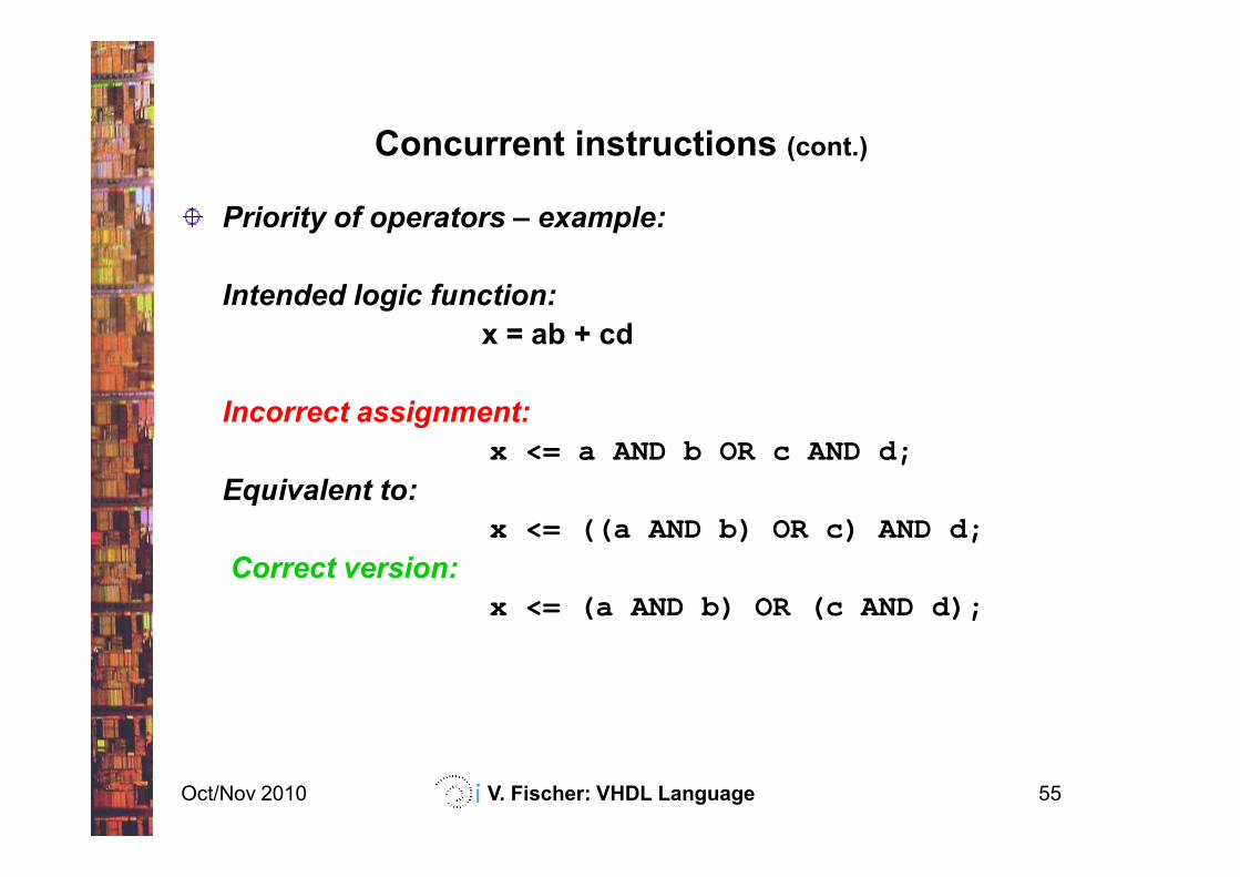
Concurrent instructions (cont.)
Priority of operators – example:
Intended logic function:
x = ab + cd
Incorrect assignment:
x <= a AND b OR c AND d;
Oct/Nov 2010 V. Fischer: VHDL Language 55
x <= a AND b OR c AND d;
Equivalent to:
x <= ((a AND b) OR c) AND d;
Correct version:
x <= (a AND b) OR (c AND d);
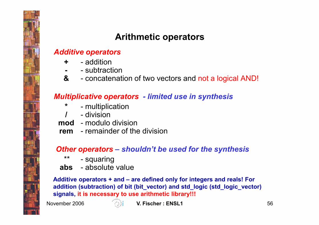
Arithmetic operators
Additive operators
+ - addition- - subtraction& - concatenation of two vectors and not a logical AND!
Multiplicative operators - limited use in synthesis
* - multiplication/ - division
November 2006 V. Fischer : ENSL1 56
/ - divisionmod - modulo divisionrem - remainder of the division
Other operators – shouldn’t be used for the synthesis
** - squaringabs - absolute value
Additive operators + and – are defined only for integers and reals! For
addition (subtraction) of bit (bit_vector) and std_logic (std_logic_vector)
signals, it is necessary to use arithmetic library!!!
Concurrent instructions (cont.)
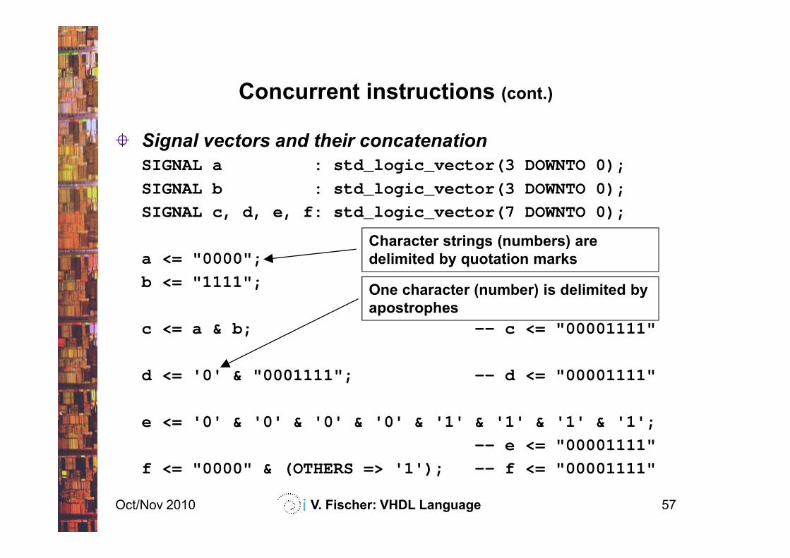
Signal vectors and their concatenation
SIGNAL a : std_logic_vector(3 DOWNTO 0);
SIGNAL b : std_logic_vector(3 DOWNTO 0);
SIGNAL c, d, e, f: std_logic_vector(7 DOWNTO 0);
a <= "0000";
b <= "1111";
Character strings (numbers) are
delimited by quotation marks
Oct/Nov 2010 V. Fischer: VHDL Language 57
b <= "1111";
c <= a & b; -- c <= "00001111"
d <= '0' & "0001111"; -- d <= "00001111"
e <= '0' & '0' & '0' & '0' & '1' & '1' & '1' & '1';
-- e <= "00001111"
f <= "0000" & (OTHERS => '1'); -- f <= "00001111"
One character (number) is delimited by
apostrophes
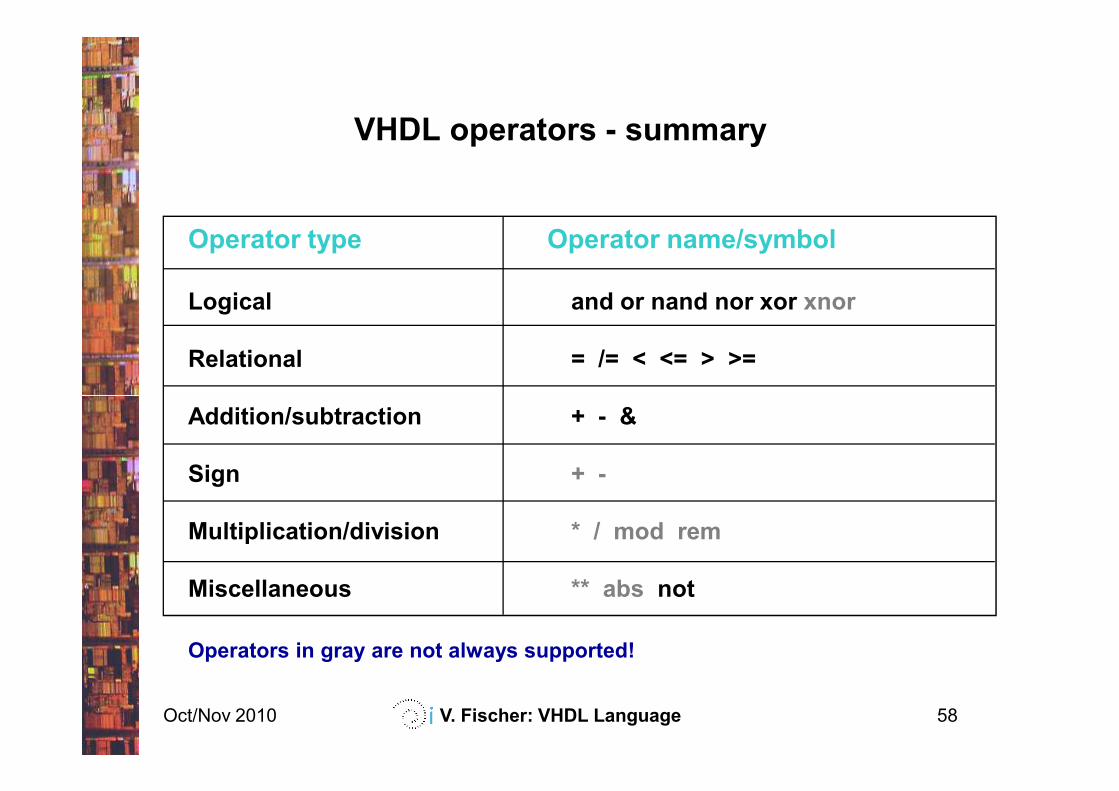
VHDL operators - summary
Operator type Operator name/symbol
Logical and or nand nor xor xnor
Relational = /= < <= > >=
Oct/Nov 2010 V. Fischer: VHDL Language 58
Addition/subtraction + - &
Sign + -
Multiplication/division * / mod rem
Miscellaneous ** abs not
Operators in gray are not always supported!
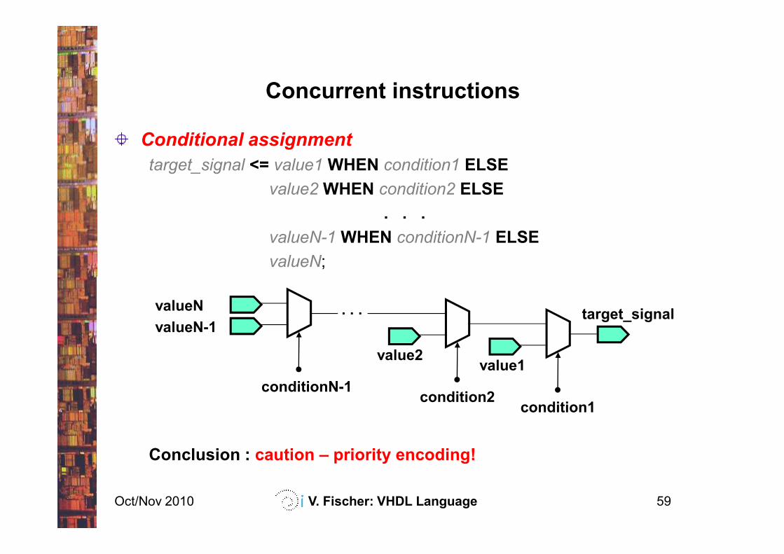
Concurrent instructions
Conditional assignment
target_signal <= value1 WHEN condition1 ELSE
value2 WHEN condition2 ELSE
. . .
valueN-1 WHEN conditionN-1 ELSE
valueN;
Oct/Nov 2010 V. Fischer: VHDL Language 59
Conclusion : caution – priority encoding!
target_signal
condition1
value1
condition2
value2
. . .
conditionN-1
valueN-1
valueN
sel1
sel2
a
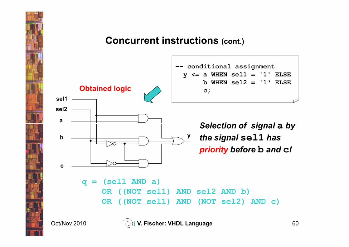
Concurrent instructions (cont.)
-- conditional assignmenty <= a WHEN sel1 = '1' ELSE
b WHEN sel2 = '1‘ ELSEc;
Selection of signal a by
Obtained logic
Oct/Nov 2010 V. Fischer: VHDL Language 60
a
b
c
y
q = (sel1 AND a) OR ((NOT sel1) AND sel2 AND b) OR ((NOT sel1) AND (NOT sel2) AND c)
Selection of signal a by
the signal sel1 has
priority before b and c !
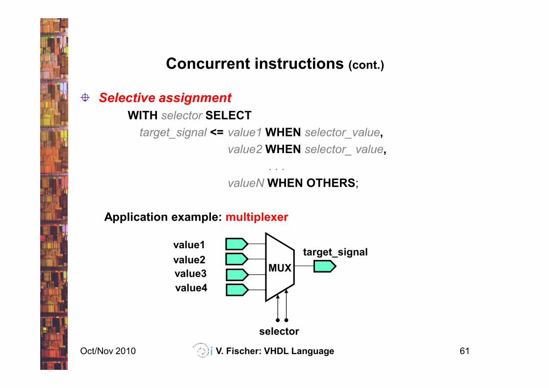
Concurrent instructions (cont.)
Selective assignment
WITH selector SELECT
target_signal <= value1 WHEN selector_value,
value2 WHEN selector_ value,
. . .
valueN WHEN OTHERS;
Oct/Nov 2010 V. Fischer: VHDL Language 61
Application example: multiplexer
target_signal
selector
value2
value1
MUXvalue3
value4
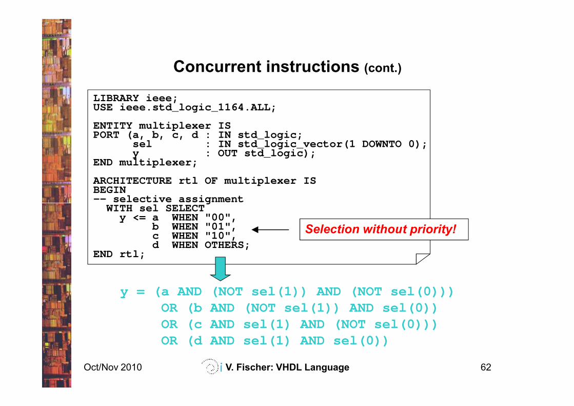
Concurrent instructions (cont.)
LIBRARY ieee;USE ieee.std_logic_1164.ALL;
ENTITY multiplexer ISPORT (a, b, c, d : IN std_logic;
sel : IN std_logic_vector(1 DOWNTO 0);y : OUT std_logic);
END multiplexer;
ARCHITECTURE rtl OF multiplexer ISBEGIN-- selective assignment
WITH sel SELECT
Oct/Nov 2010 V. Fischer: VHDL Language 62
-- selective assignmentWITH sel SELECT
y <= a WHEN "00",b WHEN "01",c WHEN "10",d WHEN OTHERS;
END rtl;
y = (a AND (NOT sel(1)) AND (NOT sel(0))) OR (b AND (NOT sel(1)) AND sel(0))OR (c AND sel(1) AND (NOT sel(0)))OR (d AND sel(1) AND sel(0))
Selection without priority!
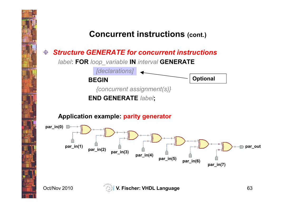
Concurrent instructions (cont.)
Structure GENERATE for concurrent instructions
label: FOR loop_variable IN interval GENERATE
[declarations]
BEGIN
{concurrent assignment(s)}
END GENERATE label;
Optional
Oct/Nov 2010 V. Fischer: VHDL Language 63
Application example: parity generator
par_in(0)
par_outpar_in(1)par_in(2)
par_in(3)par_in(4)
par_in(5)par_in(6)
par_in(7)
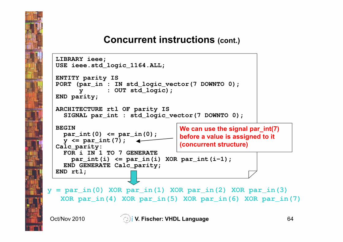
Concurrent instructions (cont.)
LIBRARY ieee;USE ieee.std_logic_1164.ALL;
ENTITY parity ISPORT (par_in : IN std_logic_vector(7 DOWNTO 0);
y : OUT std_logic);END parity;
ARCHITECTURE rtl OF parity ISSIGNAL par_int : std_logic_vector(7 DOWNTO 0);
Oct/Nov 2010 V. Fischer: VHDL Language 64
BEGINpar_int(0) <= par_in(0);y <= par_int(7);
Calc_parity:FOR i IN 1 TO 7 GENERATE
par_int(i) <= par_in(i) XOR par_int(i-1);END GENERATE Calc_parity;
END rtl;
We can use the signal par_int(7)
before a value is assigned to it
(concurrent structure)
y = par_in(0) XOR par_in(1) XOR par_in(2) XOR par_in(3) XOR par_in(4) XOR par_in(5) XOR par_in(6) XOR par_in(7)
Contents
Introduction
VHDL basics
Concurrent structures
Applications of the concurrent structures
decoders, parity checkers, multiplexers, arithmetic logic units,
comparators, tri-state outputs, bi-directional inputs/outputs
Oct/Nov 2010 V. Fischer: VHDL Language 65
comparators, tri-state outputs, bi-directional inputs/outputs
Sequential structures
Applications of the sequential structures
latches, registers, counters
State machines
Modularity and parameterization of modules
Testbenches
Applications of concurrent structures
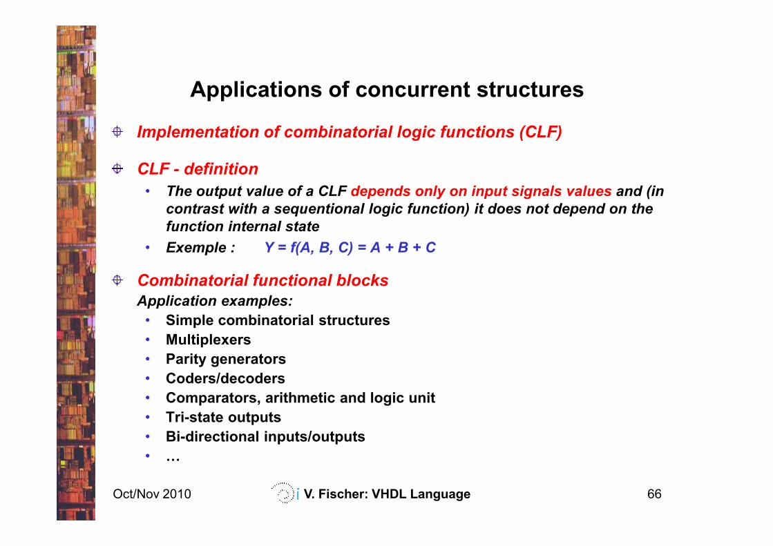
Implementation of combinatorial logic functions (CLF)
CLF - definition
• The output value of a CLF depends only on input signals values and (in
contrast with a sequentional logic function) it does not depend on the
function internal state
• Exemple : Y = f(A, B, C) = A + B + C
Combinatorial functional blocks
Oct/Nov 2010 V. Fischer: VHDL Language 66
Combinatorial functional blocks
Application examples:
• Simple combinatorial structures
• Multiplexers
• Parity generators
• Coders/decoders
• Comparators, arithmetic and logic unit
• Tri-state outputs
• Bi-directional inputs/outputs
• F
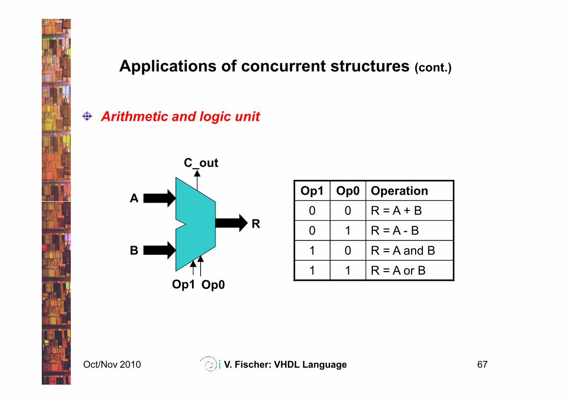
Applications of concurrent structures (cont.)
Arithmetic and logic unit
AOp1 Op0 Operation
C_out
Oct/Nov 2010 V. Fischer: VHDL Language 67
A
B
R
Op1 Op0
0 0 R = A + B
0 1 R = A - B
1 0 R = A and B
1 1 R = A or B
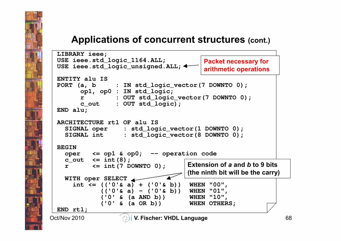
Applications of concurrent structures (cont.)
LIBRARY ieee;USE ieee.std_logic_1164.ALL;USE ieee.std_logic_unsigned.ALL;
ENTITY alu ISPORT (a, b : IN std_logic_vector(7 DOWNTO 0);
op1, op0 : IN std_logic;r : OUT std_logic_vector(7 DOWNTO 0);c_out : OUT std_logic);
END alu;
ARCHITECTURE rtl OF alu IS
Packet necessary for
arithmetic operations
Oct/Nov 2010 V. Fischer: VHDL Language 68
ARCHITECTURE rtl OF alu ISSIGNAL oper : std_logic_vector(1 DOWNTO 0);SIGNAL int : std_logic_vector(8 DOWNTO 0);
BEGINoper <= op1 & op0; -- operation codec_out <= int(8);r <= int(7 DOWNTO 0);
WITH oper SELECTint <= (('0'& a) + ('0'& b)) WHEN "00",
(('0'& a) - ('0'& b)) WHEN "01",('0' & (a AND b)) WHEN "10",('0' & (a OR b)) WHEN OTHERS;
END rtl;
Extension of a and b to 9 bits
(the ninth bit will be the carry)
Applications of concurrent structures (cont.)
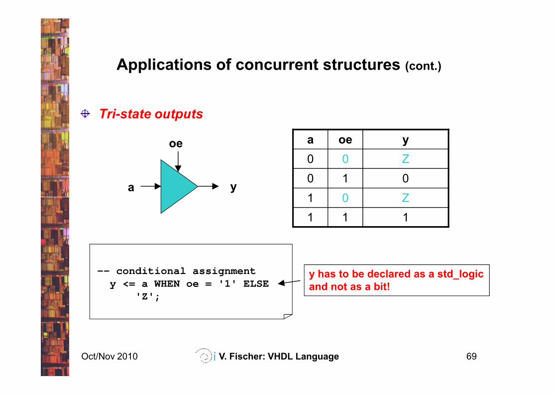
Tri-state outputs
a y
oe a oe y
0 0 Z
0 1 0
1 0 Z
Oct/Nov 2010 V. Fischer: VHDL Language 69
1 0 Z
1 1 1
-- conditional assignmenty <= a WHEN oe = '1' ELSE
'Z';
y has to be declared as a std_logic
and not as a bit!
Applications of concurrent structures (cont.)
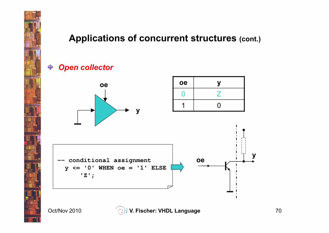
Open collector
y
oe oe y
0 Z
1 0
Oct/Nov 2010 V. Fischer: VHDL Language 70
-- conditional assignmenty <= '0' WHEN oe = '1' ELSE
'Z';
oey
Applications of concurrent structures (cont.)
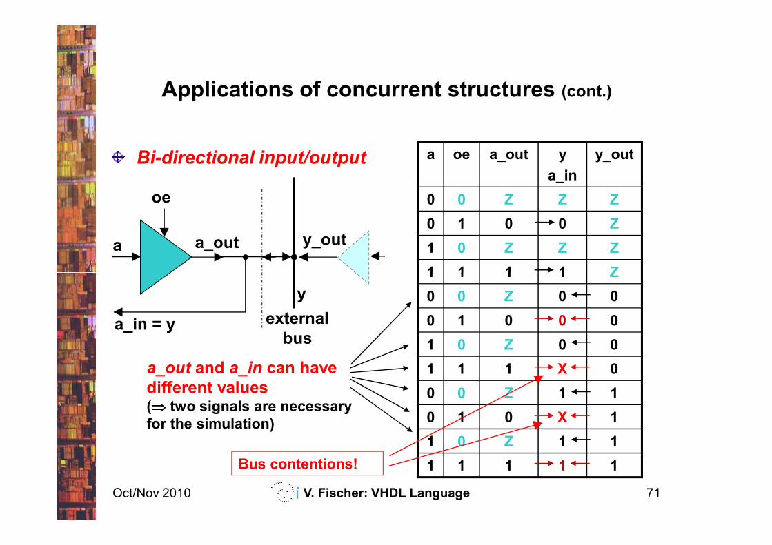
Bi-directional input/output
a
oe
a oe a_out y
a_in
y_out
0 0 Z Z Z
0 1 0 0 Z
1 0 Z Z Z
1 1 1 1 Z
a_out y_out
Oct/Nov 2010 V. Fischer: VHDL Language 71
y
1 1 1 1 Z
0 0 Z 0 0
0 1 0 0 0
1 0 Z 0 0
1 1 1 X 0
0 0 Z 1 1
0 1 0 X 1
1 0 Z 1 1
1 1 1 1 1
a_in = y external
bus
a_out and a_in can have
different values(⇒⇒⇒⇒ two signals are necessary
for the simulation)
Bus contentions!
Applications of concurrent structures (cont.)
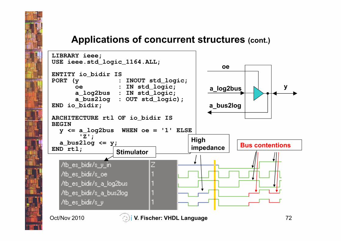
LIBRARY ieee;USE ieee.std_logic_1164.ALL;
ENTITY io_bidir ISPORT (y : INOUT std_logic;
oe : IN std_logic;a_log2bus : IN std_logic;a_bus2log : OUT std_logic);
END io_bidir;
ARCHITECTURE rtl OF io _bidir IS
a_log2bus y
a_bus2log
oe
Oct/Nov 2010 V. Fischer: VHDL Language 72
ARCHITECTURE rtl OF io _bidir ISBEGIN
y <= a_log2bus WHEN oe = '1' ELSE'Z';
a_bus2log <= y;END rtl;
StimulatorBus contentions
High
impedance
Contents
Introduction
VHDL basics
Concurrent structures
Applications of the concurrent structures
decoders, parity checkers, multiplexers, arithmetic logic units,
tri-state outputs, bi-directional inputs/outputs
Oct/Nov 2010 V. Fischer: VHDL Language 73
tri-state outputs, bi-directional inputs/outputs
Sequential structures
Applications of the sequential structures
latches, registers, counters
State machines
Modularity and parameterization of modules
Testbenches
Basic sequential structures
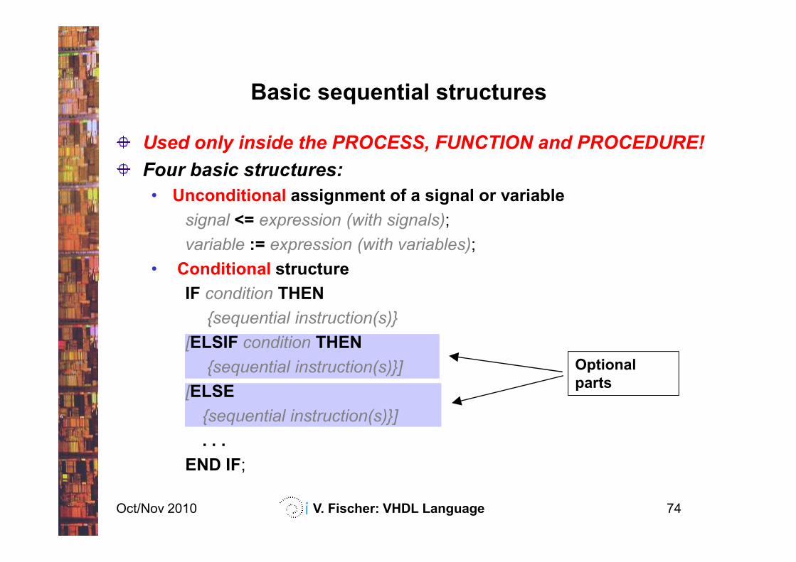
Used only inside the PROCESS, FUNCTION and PROCEDURE!
Four basic structures:
• Unconditional assignment of a signal or variable
signal <= expression (with signals);
variable := expression (with variables);
• Conditional structure
Oct/Nov 2010 V. Fischer: VHDL Language 74
Optional
parts
IF condition THEN
{sequential instruction(s)}
[ELSIF condition THEN
{sequential instruction(s)}]
[ELSE
{sequential instruction(s)}]
. . .
END IF;
Basic sequential structures (cont.)
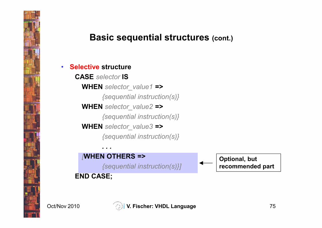
• Selective structure
CASE selector IS
WHEN selector_value1 =>
{sequential instruction(s)}
WHEN selector_value2 =>
{sequential instruction(s)}
Oct/Nov 2010 V. Fischer: VHDL Language 75
{sequential instruction(s)}
WHEN selector_value3 =>
{sequential instruction(s)}
. . .
[WHEN OTHERS =>
{sequential instruction(s)}]
END CASE;
Optional, but
recommended part
Basic sequential structures (cont.)
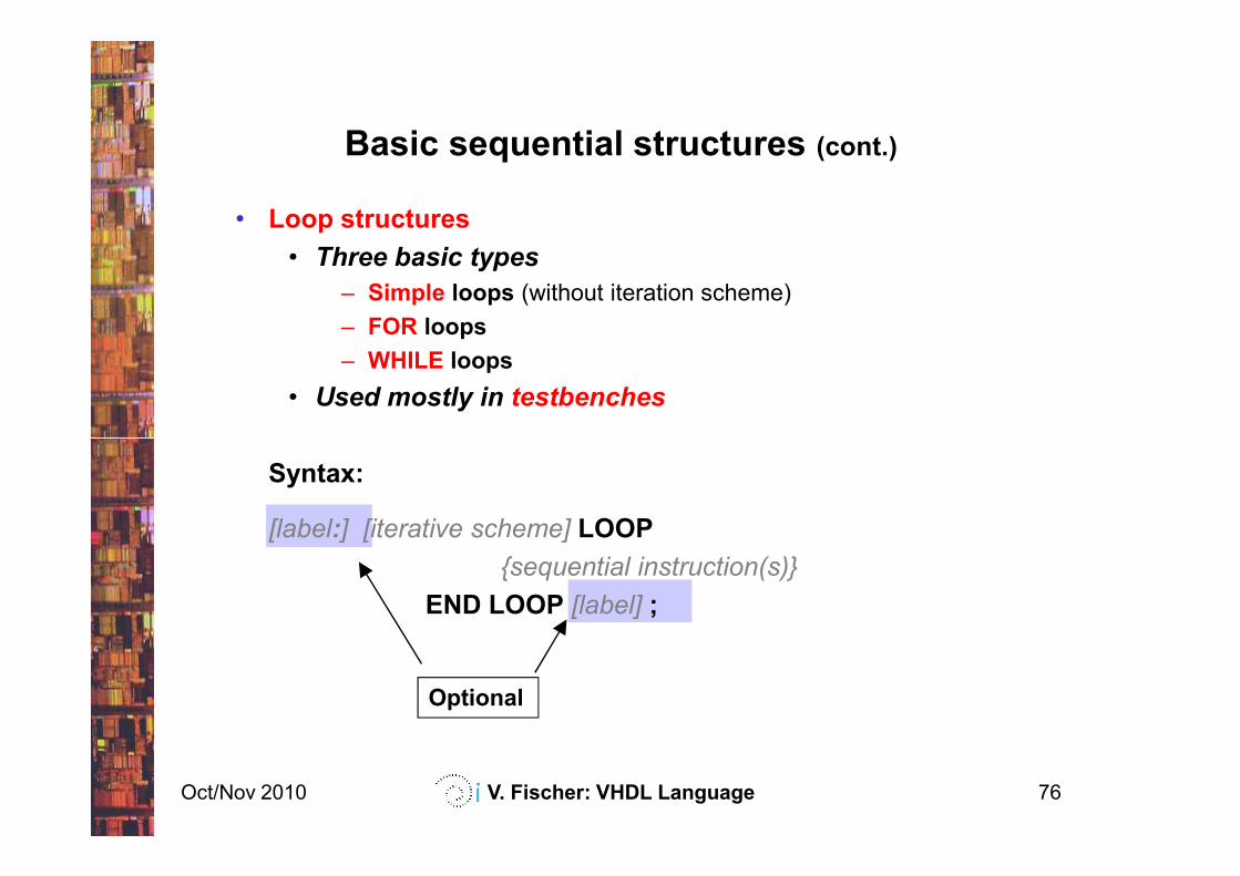
• Loop structures
• Three basic types
– Simple loops (without iteration scheme)
– FOR loops
– WHILE loops
• Used mostly in testbenches
Oct/Nov 2010 V. Fischer: VHDL Language 76
Optional
Syntax:
[label:] [iterative scheme] LOOP
{sequential instruction(s)}
END LOOP [label] ;
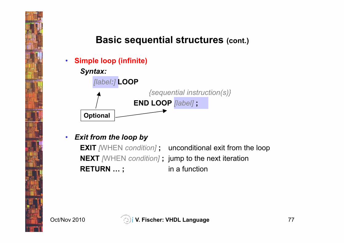
Basic sequential structures (cont.)
Optional
• Simple loop (infinite)
Syntax:
[label:] LOOP
{sequential instruction(s)}
END LOOP [label] ;
Oct/Nov 2010 V. Fischer: VHDL Language 77
• Exit from the loop by
EXIT [WHEN condition] ; unconditional exit from the loop
NEXT [WHEN condition] ; jump to the next iteration
RETURN F ; in a function
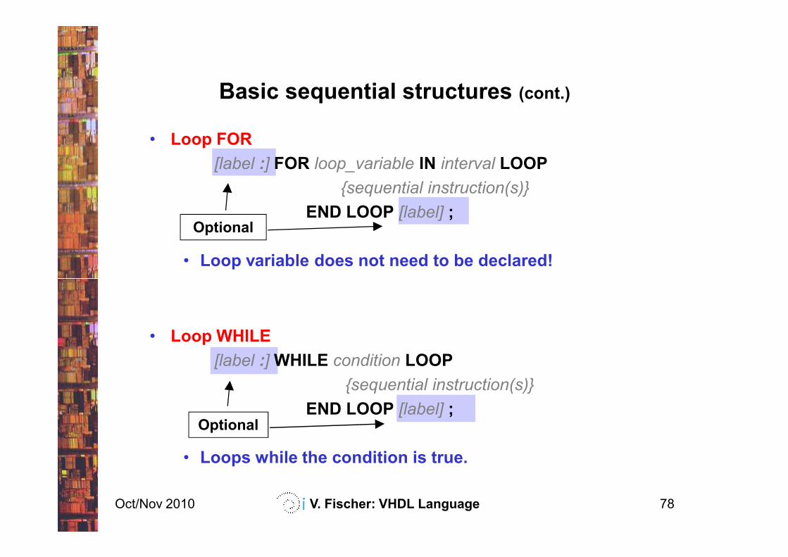
Basic sequential structures (cont.)
Optional
• Loop FOR
[label :] FOR loop_variable IN interval LOOP
{sequential instruction(s)}
END LOOP [label] ;
• Loop variable does not need to be declared!
Oct/Nov 2010 V. Fischer: VHDL Language 78
Optional
• Loop WHILE
[label :] WHILE condition LOOP
{sequential instruction(s)}
END LOOP [label] ;
• Loops while the condition is true.
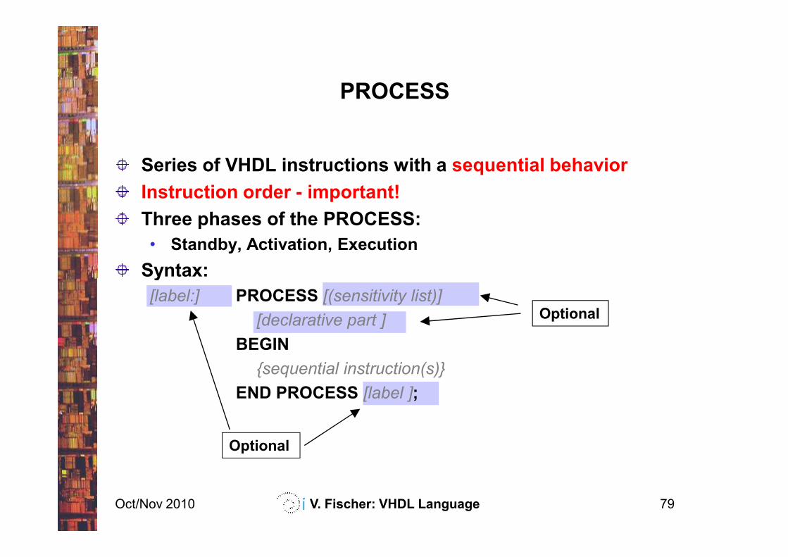
PROCESS
Series of VHDL instructions with a sequential behavior
Instruction order - important!
Three phases of the PROCESS:
• Standby, Activation, Execution
Syntax:
Oct/Nov 2010 V. Fischer: VHDL Language 79
Optional
Optional
Syntax:
[label:] PROCESS [(sensitivity list)]
[declarative part ]
BEGIN
{sequential instruction(s)}
END PROCESS [label ];
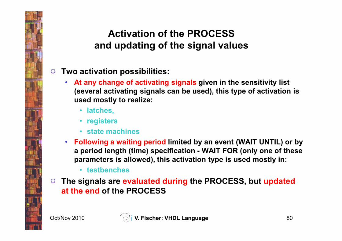
Two activation possibilities:
• At any change of activating signals given in the sensitivity list
(several activating signals can be used), this type of activation is
used mostly to realize:
• latches,
• registers
Activation of the PROCESS
and updating of the signal values
Oct/Nov 2010 V. Fischer: VHDL Language 80
• registers
• state machines
• Following a waiting period limited by an event (WAIT UNTIL) or by
a period length (time) specification - WAIT FOR (only one of these
parameters is allowed), this activation type is used mostly in:
• testbenches
The signals are evaluated during the PROCESS, but updated
at the end of the PROCESS
a
b
sel
c
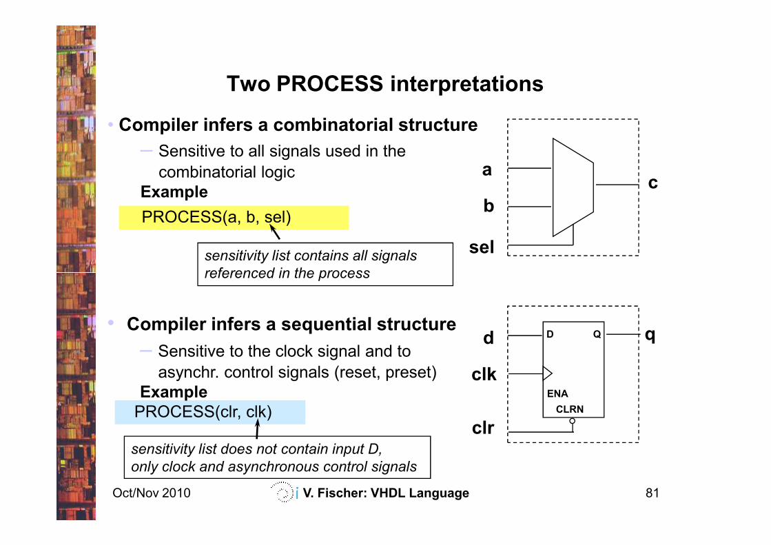
sensitivity list contains all signals
referenced in the process
Two PROCESS interpretations
• Compiler infers a combinatorial structure
– Sensitive to all signals used in the
combinatorial logic
Example
PROCESS(a, b, sel)
Oct/Nov 2010 V. Fischer: VHDL Language 81
CLRN
ENA
D Qd
clk
clr
q
referenced in the process
sensitivity list does not contain input D,
only clock and asynchronous control signals
• Compiler infers a sequential structure
– Sensitive to the clock signal and to
asynchr. control signals (reset, preset)
Example
PROCESS(clr, clk)
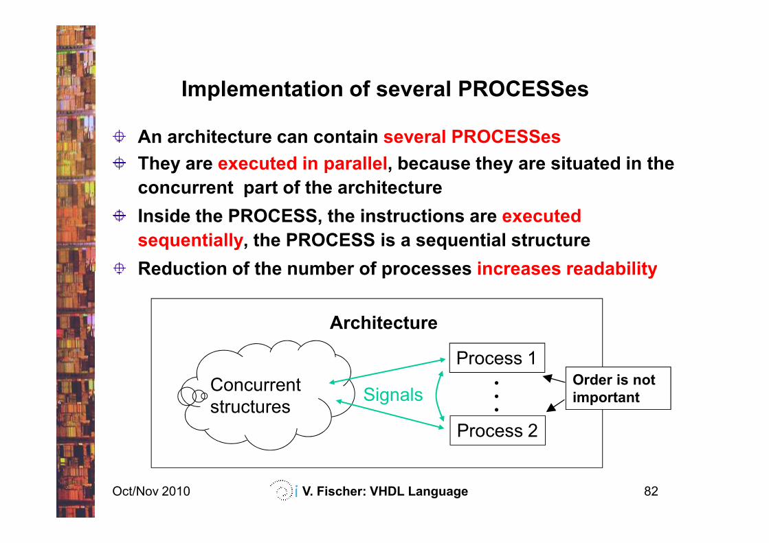
An architecture can contain several PROCESSes
They are executed in parallel, because they are situated in the
concurrent part of the architecture
Inside the PROCESS, the instructions are executed
sequentially, the PROCESS is a sequential structure
Reduction of the number of processes increases readability
Implementation of several PROCESSes
Oct/Nov 2010 V. Fischer: VHDL Language 82
Reduction of the number of processes increases readability
Architecture
Process 1...
Process 2
Concurrent
structuresSignals
Order is not
important
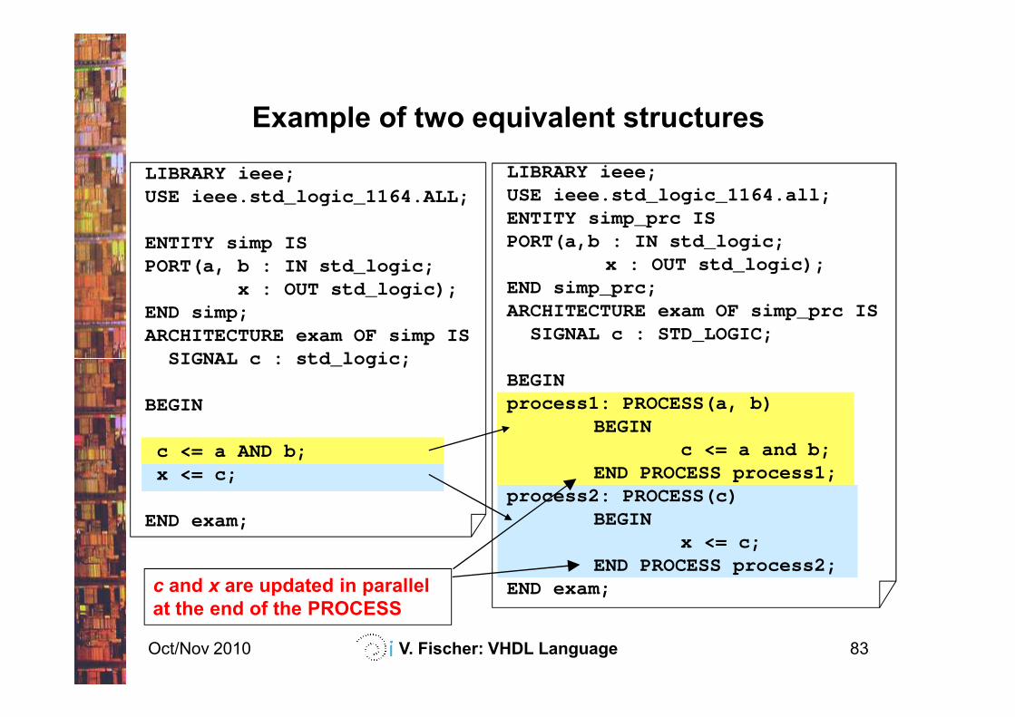
LIBRARY ieee;USE ieee.std_logic_1164.all;ENTITY simp_prc ISPORT(a,b : IN std_logic;
x : OUT std_logic);END simp_prc;ARCHITECTURE exam OF simp_prc IS
SIGNAL c : STD_LOGIC;
Example of two equivalent structures
LIBRARY ieee;USE ieee.std_logic_1164.ALL;
ENTITY simp ISPORT(a, b : IN std_logic;
x : OUT std_logic);END simp;ARCHITECTURE exam OF simp IS
SIGNAL c : std_logic;
Oct/Nov 2010 V. Fischer: VHDL Language 83
BEGINprocess1: PROCESS(a, b)
BEGINc <= a and b;
END PROCESS process1;process2: PROCESS(c)
BEGINx <= c;
END PROCESS process2;END exam;c and x are updated in parallel
at the end of the PROCESS
SIGNAL c : std_logic;
BEGIN
c <= a AND b;x <= c;
END exam;
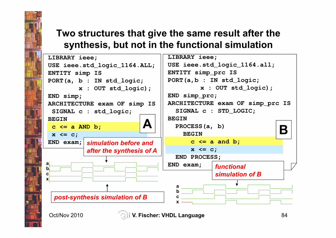
LIBRARY ieee;USE ieee.std_logic_1164.all;ENTITY simp_prc ISPORT(a,b : IN std_logic;
x : OUT std_logic);END simp_prc;ARCHITECTURE exam OF simp_prc IS
SIGNAL c : STD_LOGIC;BEGIN
Two structures that give the same result after the
synthesis, but not in the functional simulation
LIBRARY ieee;USE ieee.std_logic_1164.ALL;ENTITY simp ISPORT(a, b : IN std_logic;
x : OUT std_logic);END simp;ARCHITECTURE exam OF simp IS
SIGNAL c : std_logic;BEGIN
A
Oct/Nov 2010 V. Fischer: VHDL Language 84
BEGINPROCESS(a, b)
BEGINc <= a and b;x <= c;
END PROCESS;END exam;
BEGINc <= a AND b;x <= c;
END exam;
abcx
abcx
A Bsimulation before and
after the synthesis of A
functional
simulation of B
post-synthesis simulation of B
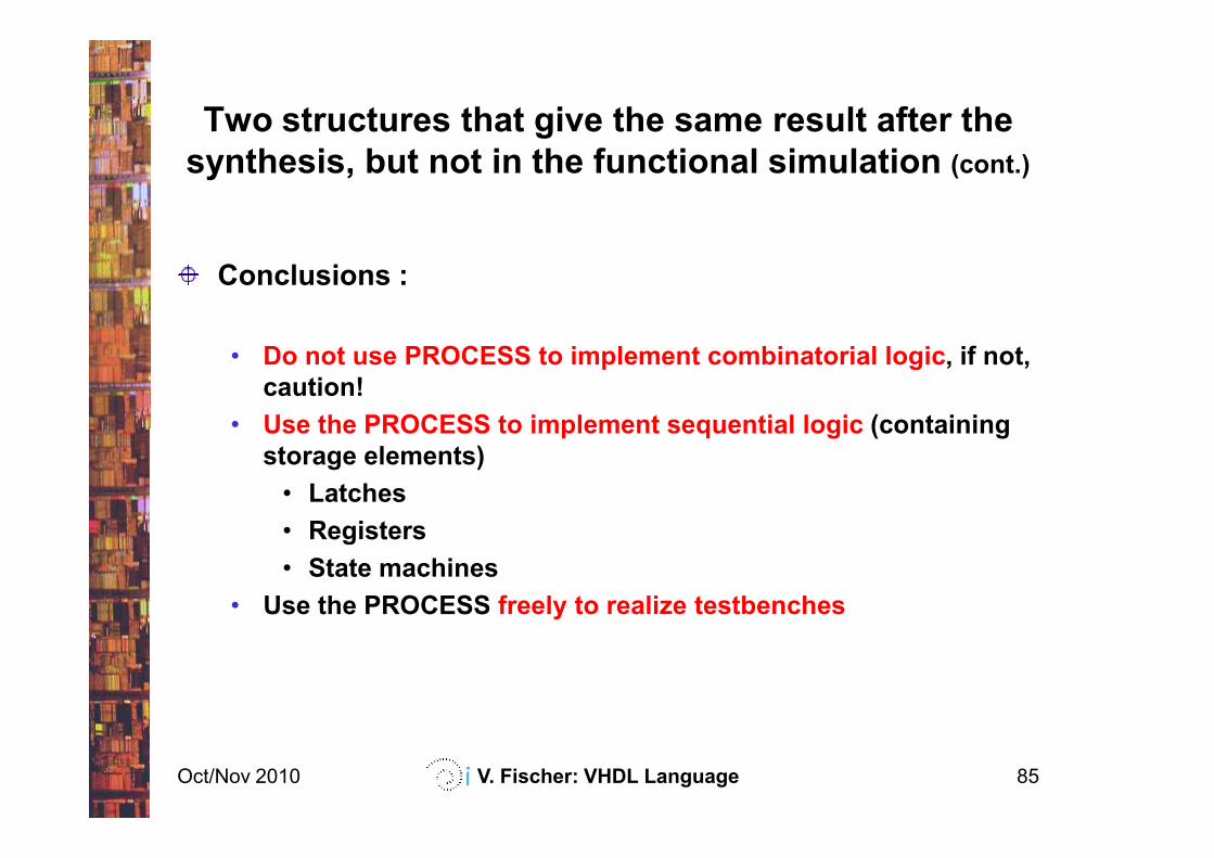
Two structures that give the same result after the
synthesis, but not in the functional simulation (cont.)
Conclusions :
• Do not use PROCESS to implement combinatorial logic, if not,
caution!
• Use the PROCESS to implement sequential logic (containing
Oct/Nov 2010 V. Fischer: VHDL Language 85
• Use the PROCESS to implement sequential logic (containing
storage elements)
• Latches
• Registers
• State machines
• Use the PROCESS freely to realize testbenches
Contents
Introduction
VHDL basics
Concurrent structures
Applications of the concurrent structures
decoders, parity checkers, multiplexers, arithmetic logic units,
tri-state outputs, bi-directional inputs/outputs
Oct/Nov 2010 V. Fischer: VHDL Language 86
tri-state outputs, bi-directional inputs/outputs
Sequential structures
Applications of the sequential structures
latches, registers, counters
State machines
Modularity and parameterization of modules
Testbenches
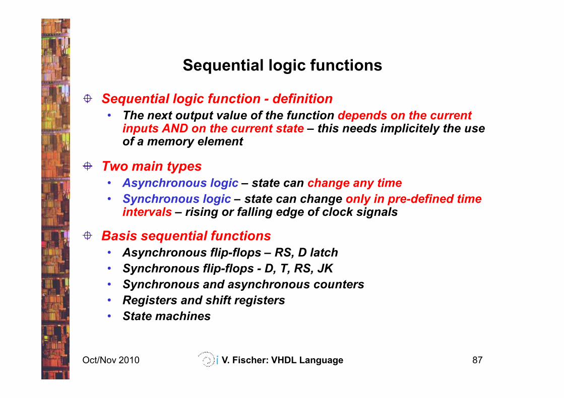
Sequential logic functions
Sequential logic function - definition
• The next output value of the function depends on the current inputs AND on the current state – this needs implicitely the use of a memory element
Two main types
• Asynchronous logic – state can change any time
• Synchronous logic – state can change only in pre-defined time
Oct/Nov 2010 V. Fischer: VHDL Language 87
• Synchronous logic – state can change only in pre-defined time intervals – rising or falling edge of clock signals
Basis sequential functions
• Asynchronous flip-flops – RS, D latch
• Synchronous flip-flops - D, T, RS, JK
• Synchronous and asynchronous counters
• Registers and shift registers
• State machines
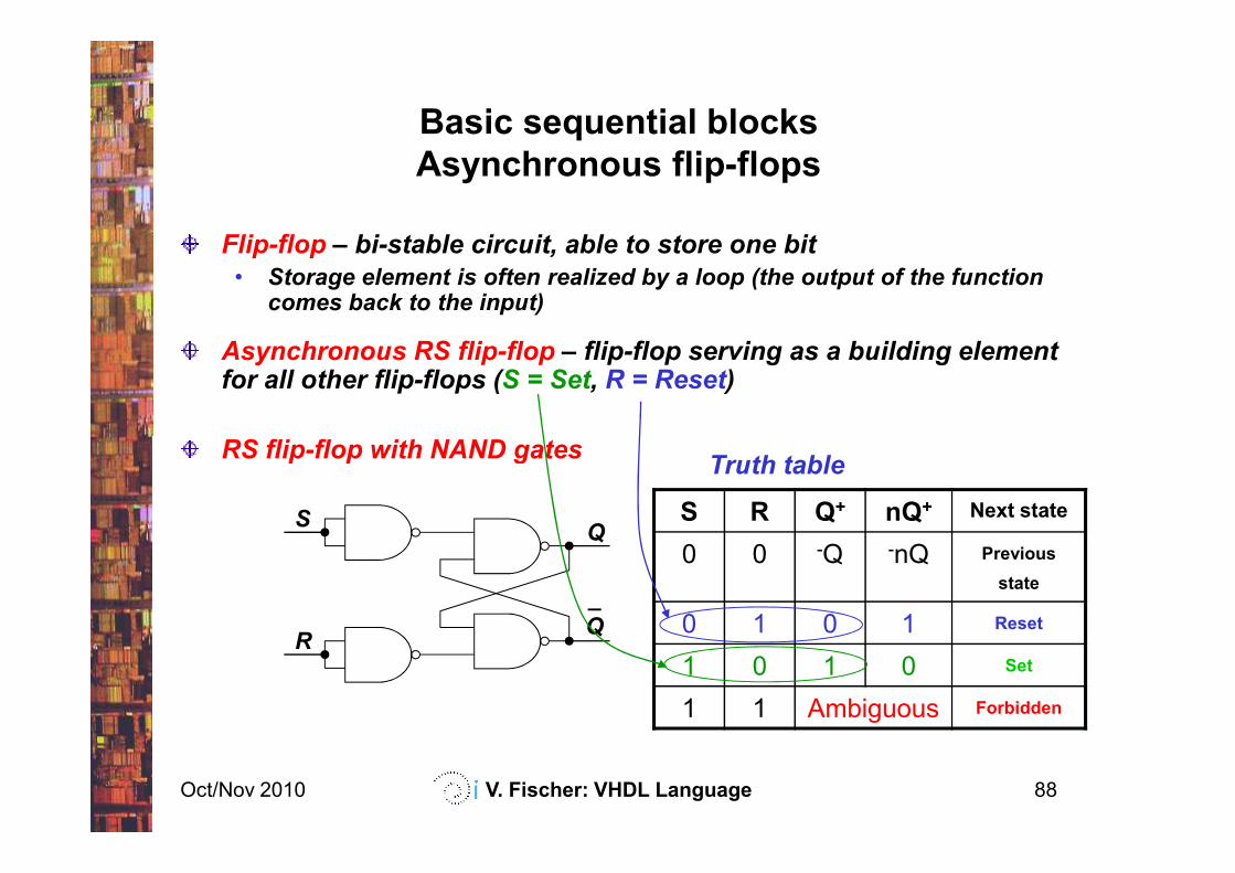
Basic sequential blocks
Asynchronous flip-flops
Flip-flop – bi-stable circuit, able to store one bit
• Storage element is often realized by a loop (the output of the function comes back to the input)
Asynchronous RS flip-flop – flip-flop serving as a building element for all other flip-flops (S = Set, R = Reset)
RS flip-flop with NAND gates
Oct/Nov 2010 V. Fischer: VHDL Language 88
RS flip-flop with NAND gates
S R Q+ nQ+ Next state
0 0 -Q -nQ Previous
state
0 1 0 1 Reset
1 0 1 0 Set
1 1 Ambiguous Forbidden
SQ
_
QR
Truth table
Basic sequential blocks
Asynchronous flip-flops (cont.)
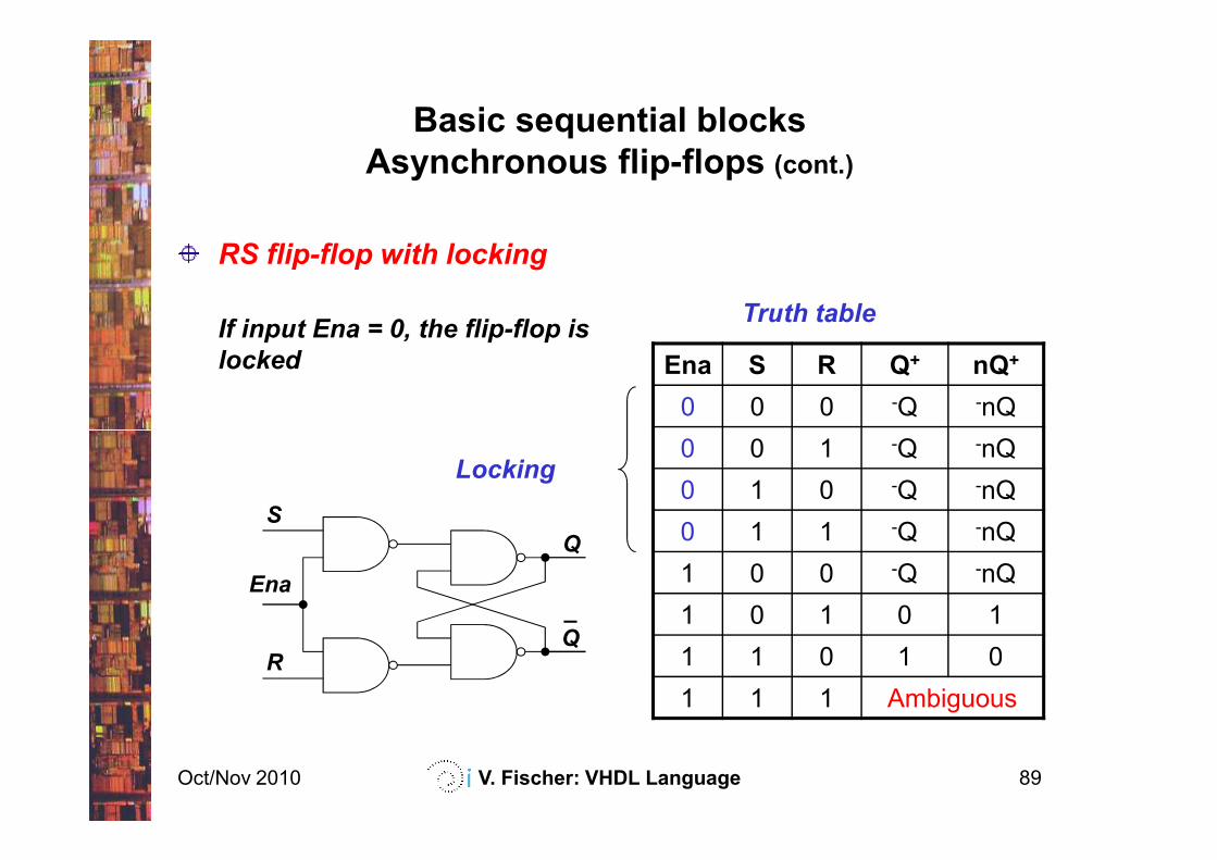
RS flip-flop with locking
If input Ena = 0, the flip-flop is
locked Ena S R Q+ nQ+
0 0 0 -Q -nQ
Truth table
Oct/Nov 2010 V. Fischer: VHDL Language 89
0 0 1 -Q -nQ
0 1 0 -Q -nQ
0 1 1 -Q -nQ
1 0 0 -Q -nQ
1 0 1 0 1
1 1 0 1 0
1 1 1 Ambiguous
S
Q
_
QR
Ena
Locking
Basic sequential blocks
Asynchronous flip-flops (cont.)
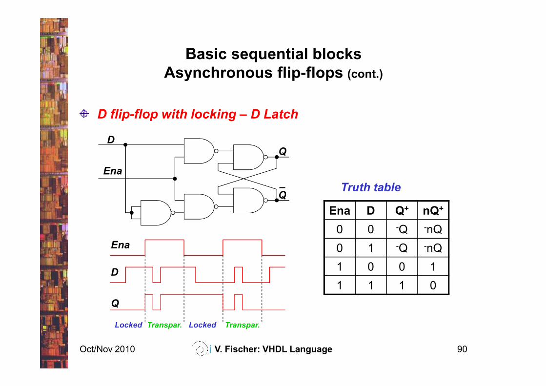
D flip-flop with locking – D Latch
DQ
_
QTruth table
Ena
Oct/Nov 2010 V. Fischer: VHDL Language 90
Q
Ena D Q+ nQ+
0 0 -Q -nQ
0 1 -Q -nQ
1 0 0 1
1 1 1 0
Truth table
D
Ena
Q
Locked Transpar. Locked Transpar.
Basic sequential blocks
Asynchronous flip-flops (cont.)
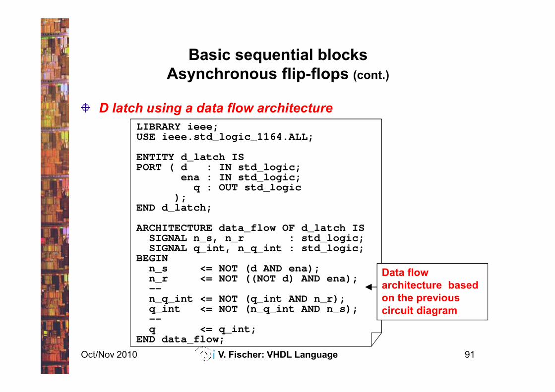
D latch using a data flow architecture
LIBRARY ieee;USE ieee.std_logic_1164.ALL;
ENTITY d_latch ISPORT ( d : IN std_logic;
ena : IN std_logic;q : OUT std_logic
);
Oct/Nov 2010 V. Fischer: VHDL Language 91
);END d_latch;
ARCHITECTURE data_flow OF d_latch ISSIGNAL n_s, n_r : std_logic;SIGNAL q_int, n_q_int : std_logic;
BEGINn_s <= NOT (d AND ena);n_r <= NOT ((NOT d) AND ena);--n_q_int <= NOT (q_int AND n_r);q_int <= NOT (n_q_int AND n_s);--q <= q_int;
END data_flow;
Data flow
architecture based
on the previous
circuit diagram
Basic sequential blocks
Asynchronous flip-flops (cont.)
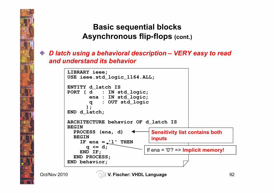
D latch using a behavioral description – VERY easy to read
and understand its behavior
LIBRARY ieee;USE ieee.std_logic_1164.ALL;
ENTITY d_latch ISPORT ( d : IN std_logic;
ena : IN std_logic;
Oct/Nov 2010 V. Fischer: VHDL Language 92
ena : IN std_logic;q : OUT std_logic
);END d_latch;
ARCHITECTURE behavior OF d_latch ISBEGIN
PROCESS (ena, d)BEGIN
IF ena = '1' THENq <= d;
END IF;END PROCESS;
END behavior;
Sensitivity list contains both
inputs
If ena = '0'? => Implicit memory!
Basic sequential blocks
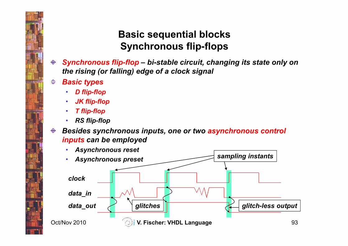
Synchronous flip-flops
Synchronous flip-flop – bi-stable circuit, changing its state only on
the rising (or falling) edge of a clock signal
Basic types
• D flip-flop
• JK flip-flop
• T flip-flop
• RS flip-flop
Oct/Nov 2010 V. Fischer: VHDL Language 93
• RS flip-flop
Besides synchronous inputs, one or two asynchronous control
inputs can be employed
• Asynchronous reset
• Asynchronous preset
clock
data_in
data_out glitches
sampling instants
glitch-less output
Basic sequential blocks
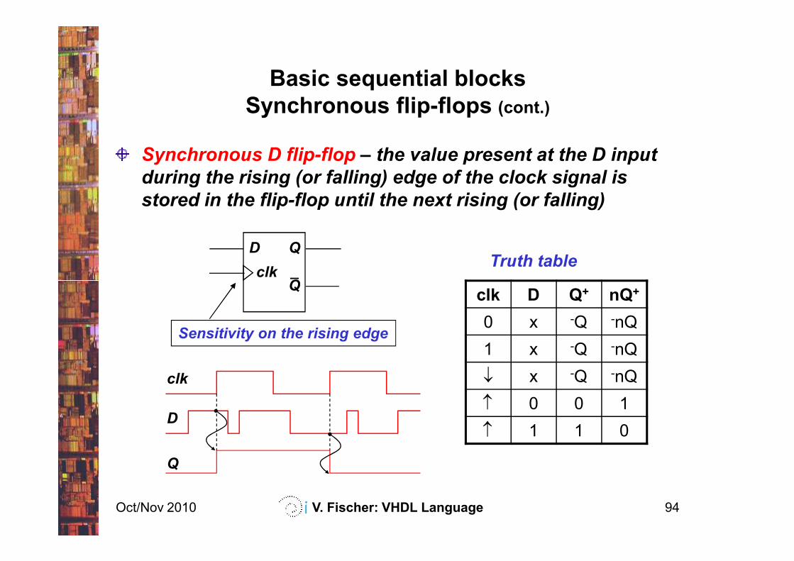
Synchronous flip-flops (cont.)
Synchronous D flip-flop – the value present at the D input
during the rising (or falling) edge of the clock signal is
stored in the flip-flop until the next rising (or falling)
D
clk
QTruth table
_Q
Oct/Nov 2010 V. Fischer: VHDL Language 94
clk D Q+ nQ+
0 x -Q -nQ
1 x -Q -nQ
↓ x -Q -nQ
↑ 0 0 1
↑ 1 1 0
Q
Sensitivity on the rising edge
D
clk
Q
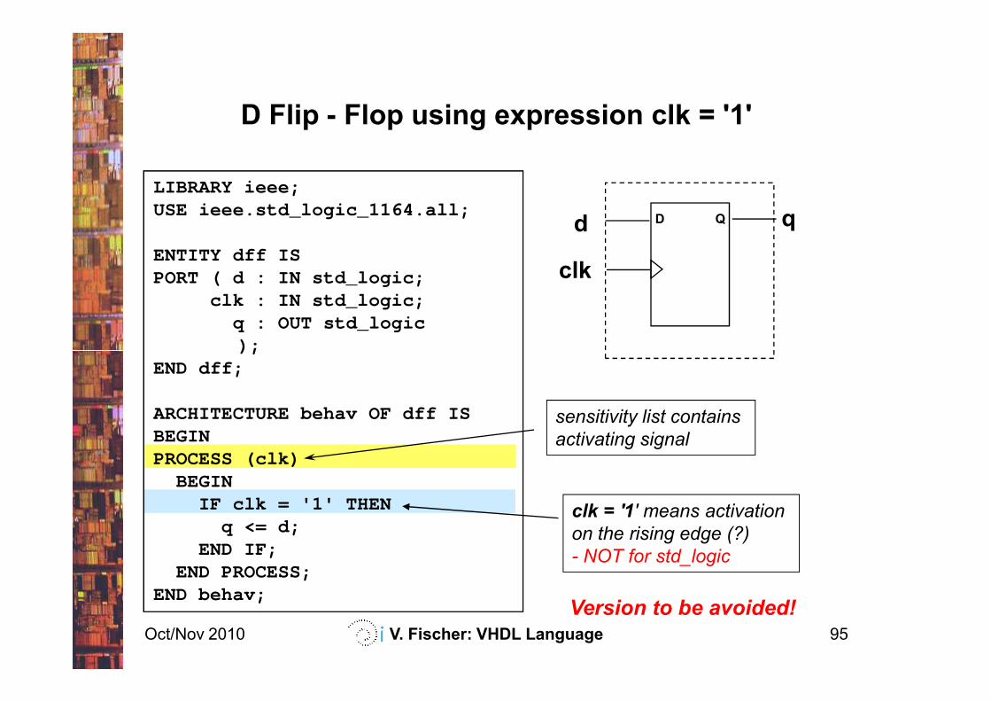
D Flip - Flop using expression clk = '1'
LIBRARY ieee;USE ieee.std_logic_1164.all;
ENTITY dff ISPORT ( d : IN std_logic;
clk : IN std_logic;q : OUT std_logic);
D Qd
clk
q
Oct/Nov 2010 V. Fischer: VHDL Language 95
sensitivity list contains
activating signal
);END dff;
ARCHITECTURE behav OF dff ISBEGINPROCESS (clk)
BEGINIF clk = '1' THEN
q <= d;END IF;
END PROCESS;END behav;
clk = '1' means activation
on the rising edge (?)
- NOT for std_logic
Version to be avoided!
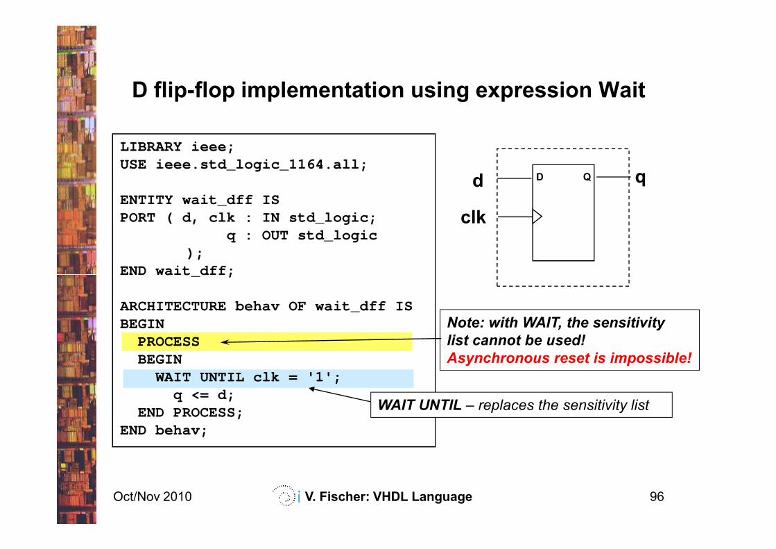
LIBRARY ieee;USE ieee.std_logic_1164.all;
ENTITY wait_dff ISPORT ( d, clk : IN std_logic;
q : OUT std_logic);
END wait_dff;
D flip-flop implementation using expression Wait
D Qd
clk
q
Oct/Nov 2010 V. Fischer: VHDL Language 96
END wait_dff;
ARCHITECTURE behav OF wait_dff ISBEGIN
PROCESS BEGIN
WAIT UNTIL clk = '1';q <= d;
END PROCESS;END behav;
Note: with WAIT, the sensitivity
list cannot be used!
Asynchronous reset is impossible!
WAIT UNTIL – replaces the sensitivity list
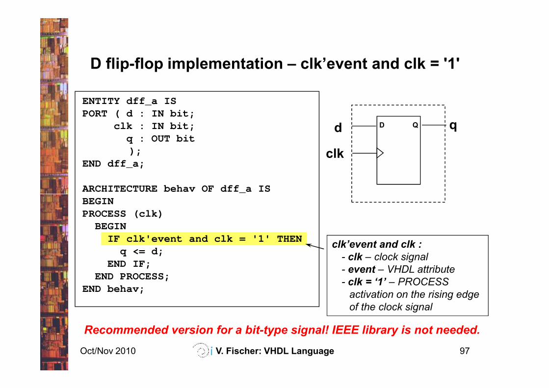
ENTITY dff_a ISPORT ( d : IN bit;
clk : IN bit;q : OUT bit);
END dff_a;
ARCHITECTURE behav OF dff_a IS
D flip-flop implementation – clk’event and clk = '1'
D Qd
clk
q
Oct/Nov 2010 V. Fischer: VHDL Language 97
ARCHITECTURE behav OF dff_a ISBEGINPROCESS (clk)
BEGINIF clk'event and clk = '1' THEN
q <= d;END IF;
END PROCESS;END behav;
clk’event and clk :
- clk – clock signal
- event – VHDL attribute
- clk = ‘1’ – PROCESS
activation on the rising edge
of the clock signal
Recommended version for a bit-type signal! IEEE library is not needed.
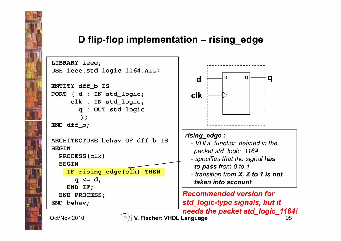
LIBRARY ieee;USE ieee.std_logic_1164.ALL;
ENTITY dff_b ISPORT ( d : IN std_logic;
clk : IN std_logic;q : OUT std_logic);
D flip-flop implementation – rising_edge
D Qd
clk
q
Oct/Nov 2010 V. Fischer: VHDL Language 98
);END dff_b;
ARCHITECTURE behav OF dff_b ISBEGIN
PROCESS(clk)BEGIN
IF rising_edge(clk) THENq <= d;
END IF;END PROCESS;
END behav;
rising_edge :
- VHDL function defined in the
packet std_logic_1164
- specifies that the signal has
to pass from 0 to 1
- transition from X, Z to 1 is not
taken into account
Recommended version for
std_logic-type signals, but it
needs the packet std_logic_1164!
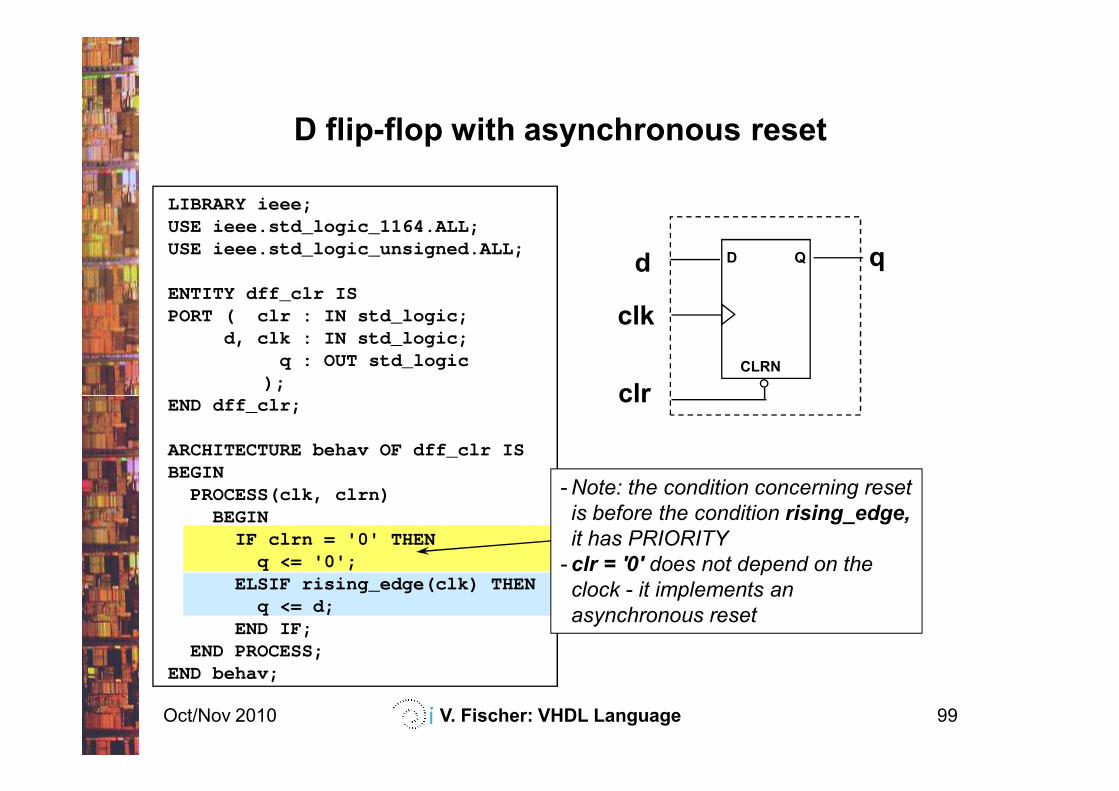
LIBRARY ieee;USE ieee.std_logic_1164.ALL;USE ieee.std_logic_unsigned.ALL;
ENTITY dff_clr ISPORT ( clr : IN std_logic;
d, clk : IN std_logic;q : OUT std_logic
);END dff_clr ;
D flip-flop with asynchronous reset
CLRN
D Qd
clk
clr
q
Oct/Nov 2010 V. Fischer: VHDL Language 99
END dff_clr ;
ARCHITECTURE behav OF dff_clr ISBEGIN
PROCESS(clk, clrn)BEGIN
IF clrn = '0' THENq <= '0';
ELSIF rising_edge(clk) THENq <= d;
END IF;END PROCESS;
END behav;
clr
-Note: the condition concerning reset
is before the condition rising_edge,
it has PRIORITY
- clr = '0' does not depend on the
clock - it implements an
asynchronous reset
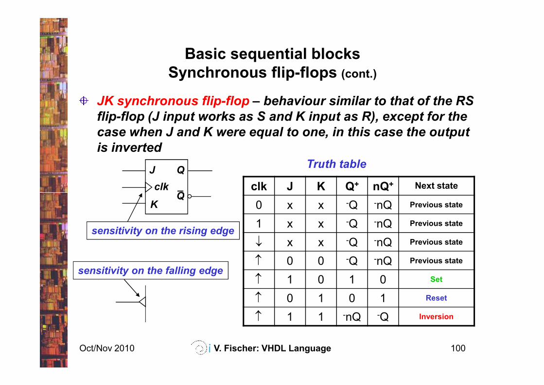
Basic sequential blocks
Synchronous flip-flops (cont.)
JK synchronous flip-flop – behaviour similar to that of the RS
flip-flop (J input works as S and K input as R), except for the
case when J and K were equal to one, in this case the output
is inverted
J
clk
Q
clk J K Q+ nQ+ Next state
Truth table
_Q
Oct/Nov 2010 V. Fischer: VHDL Language 100
clk J K Q nQ
0 x x -Q -nQ Previous state
1 x x -Q -nQ Previous state
↓ x x -Q -nQ Previous state
↑ 0 0 -Q -nQ Previous state
↑ 1 0 1 0 Set
↑ 0 1 0 1 Reset
↑ 1 1 -nQ -Q Inversion
QK
sensitivity on the rising edge
sensitivity on the falling edge
Basic sequential blocks
Synchronous flip-flops (cont.)
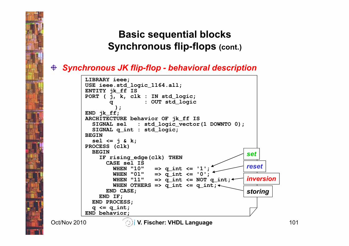
Synchronous JK flip-flop - behavioral description
LIBRARY ieee;USE ieee.std_logic_1164.all;ENTITY jk_ff ISPORT ( j, k, clk : IN std_logic;
q : OUT std_logic);
END jk_ff;ARCHITECTURE behavior OF jk_ff IS
SIGNAL sel : std_logic_vector(1 DOWNTO 0);
Oct/Nov 2010 V. Fischer: VHDL Language 101
SIGNAL sel : std_logic_vector(1 DOWNTO 0);SIGNAL q_int : std_logic;
BEGINsel <= j & k;
PROCESS (clk)BEGIN
IF rising_edge(clk) THENCASE sel IS
WHEN "10" => q_int <= '1';WHEN "01" => q_int <= '0';WHEN "11" => q_int <= NOT q_int;WHEN OTHERS => q_int <= q_int;
END CASE;END IF;
END PROCESS;q <= q_int;
END behavior;
set
reset
inversion
storing
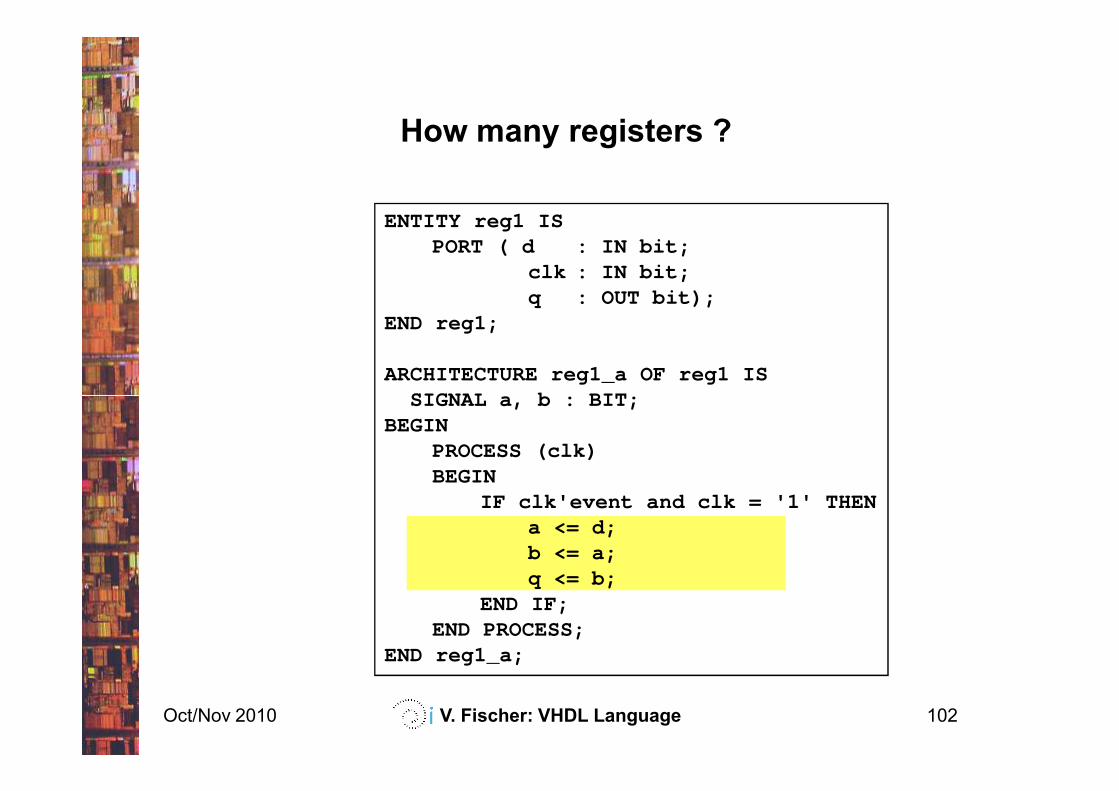
ENTITY reg1 ISPORT ( d : IN bit;
clk : IN bit;q : OUT bit);
END reg1;
ARCHITECTURE reg1_a OF reg1 ISSIGNAL a, b : BIT;
How many registers ?
Oct/Nov 2010 V. Fischer: VHDL Language 102
SIGNAL a, b : BIT;BEGIN
PROCESS (clk)BEGIN
IF clk'event and clk = '1' THENa <= d;b <= a;q <= b;
END IF;END PROCESS;
END reg1_a;
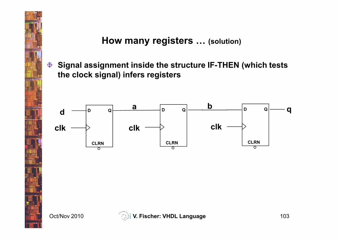
How many registers F (solution)
D Q qbD QD Qd
a
Signal assignment inside the structure IF-THEN (which tests
the clock signal) infers registers
Oct/Nov 2010 V. Fischer: VHDL Language 103
CLRN
clk
CLRN
clk
CLRN
clk
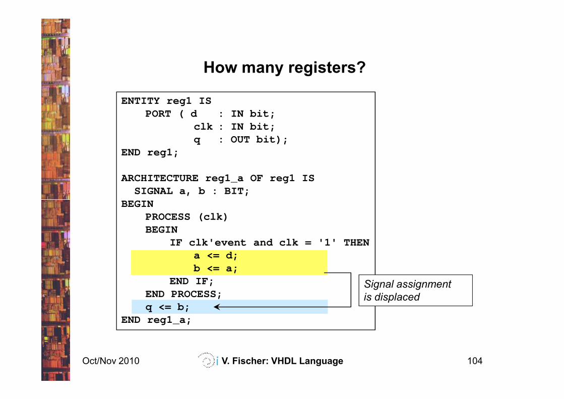
ENTITY reg1 ISPORT ( d : IN bit;
clk : IN bit;q : OUT bit);
END reg1;
ARCHITECTURE reg1_a OF reg1 ISSIGNAL a, b : BIT;
BEGIN
How many registers?
Oct/Nov 2010 V. Fischer: VHDL Language 104
BEGINPROCESS (clk)BEGIN
IF clk'event and clk = '1' THENa <= d;b <= a;
END IF;END PROCESS;q <= b;
END reg1_a;
Signal assignment
is displaced
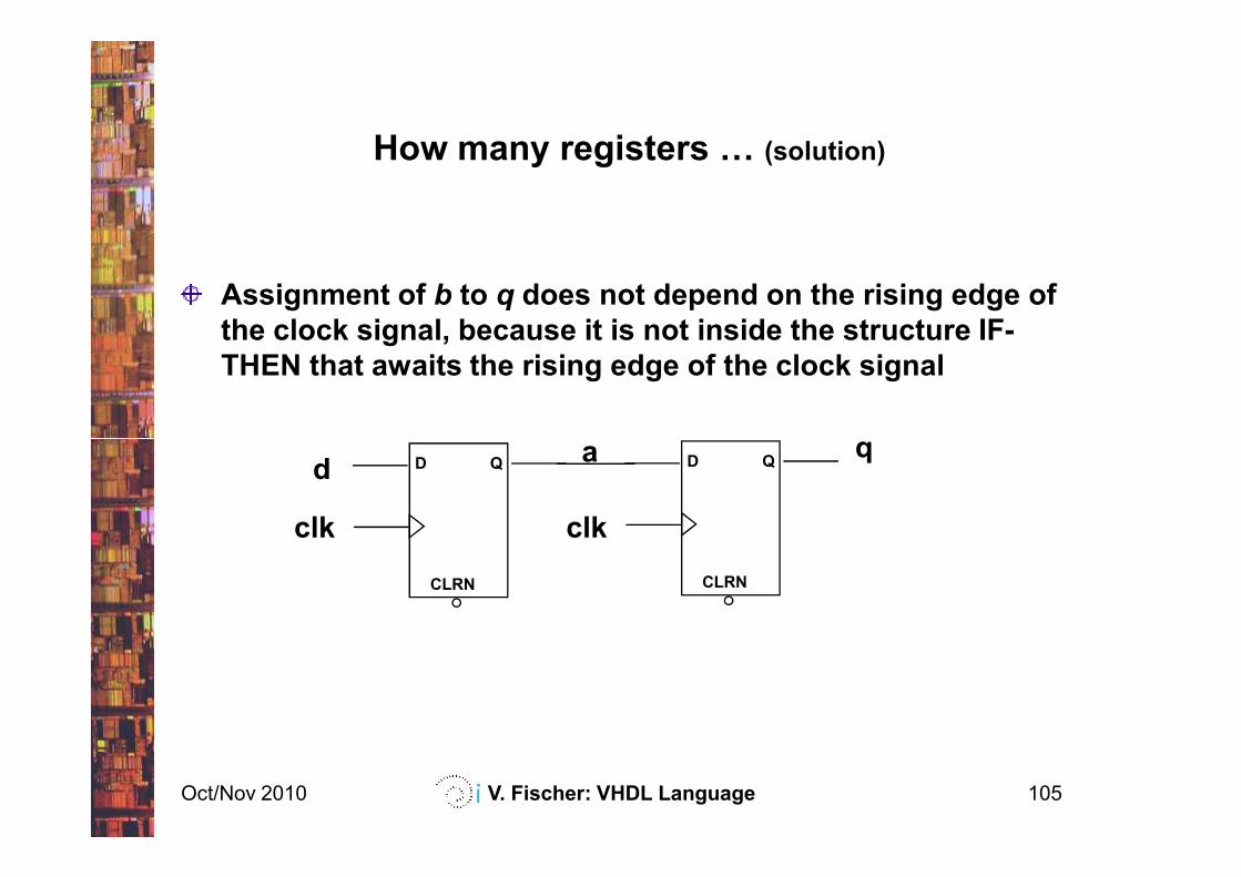
How many registers F (solution)
Assignment of b to q does not depend on the rising edge of
the clock signal, because it is not inside the structure IF-
THEN that awaits the rising edge of the clock signal
qa
Oct/Nov 2010 V. Fischer: VHDL Language 105
q
CLRN
D Q
clk
CLRN
D Qd
clk
a
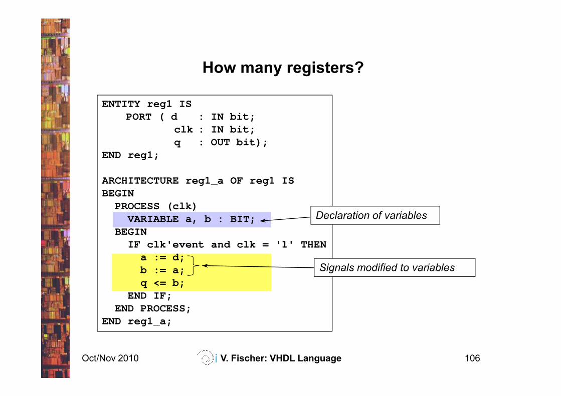
ENTITY reg1 ISPORT ( d : IN bit;
clk : IN bit;q : OUT bit);
END reg1;
ARCHITECTURE reg1_a OF reg1 ISBEGIN
How many registers?
Oct/Nov 2010 V. Fischer: VHDL Language 106
BEGINPROCESS (clk)
VARIABLE a, b : BIT;BEGIN
IF clk'event and clk = '1' THENa := d;b := a;q <= b;
END IF;END PROCESS;
END reg1_a;
Signals modified to variables
Declaration of variables
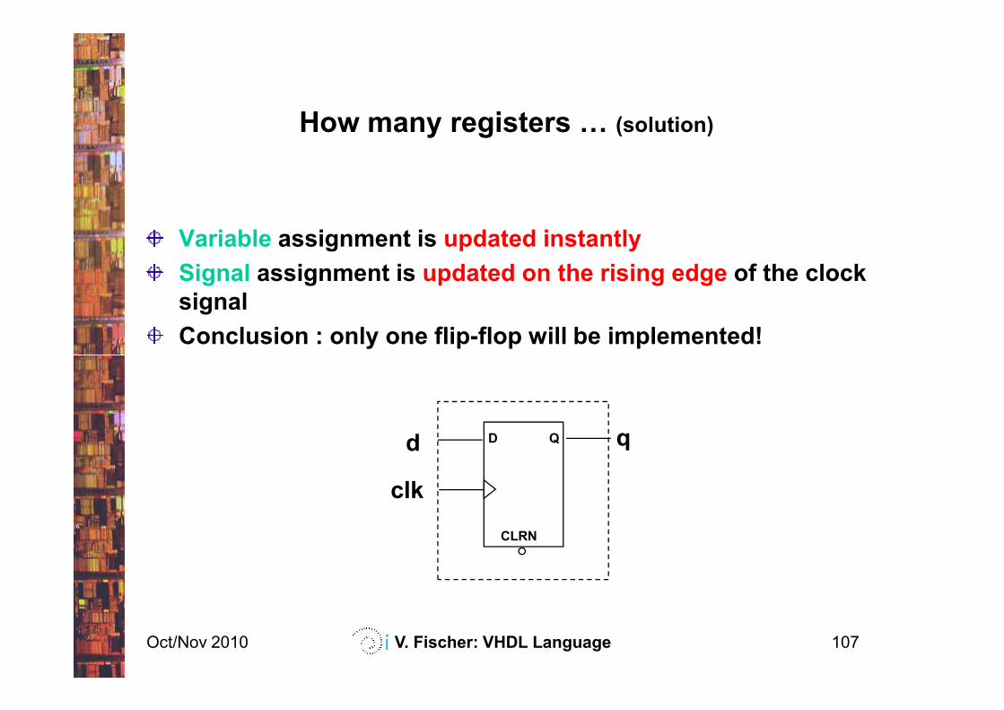
How many registers F (solution)
Variable assignment is updated instantly
Signal assignment is updated on the rising edge of the clock
signal
Conclusion : only one flip-flop will be implemented!
Oct/Nov 2010 V. Fischer: VHDL Language 107
CLRN
D Qd
clk
q
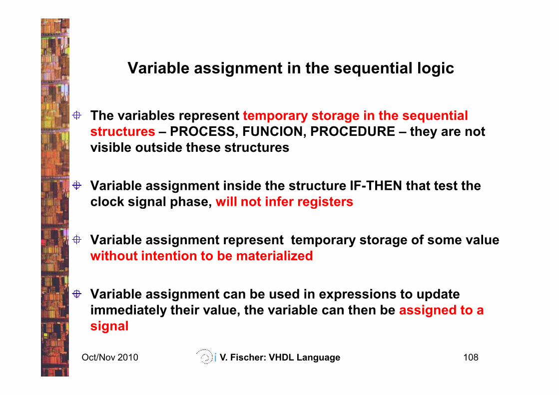
Variable assignment in the sequential logic
The variables represent temporary storage in the sequential
structures – PROCESS, FUNCION, PROCEDURE – they are not
visible outside these structures
Variable assignment inside the structure IF-THEN that test the
clock signal phase, will not infer registers
Oct/Nov 2010 V. Fischer: VHDL Language 108
clock signal phase, will not infer registers
Variable assignment represent temporary storage of some value
without intention to be materialized
Variable assignment can be used in expressions to update
immediately their value, the variable can then be assigned to a
signal
q
clk
rstCMPT
updn
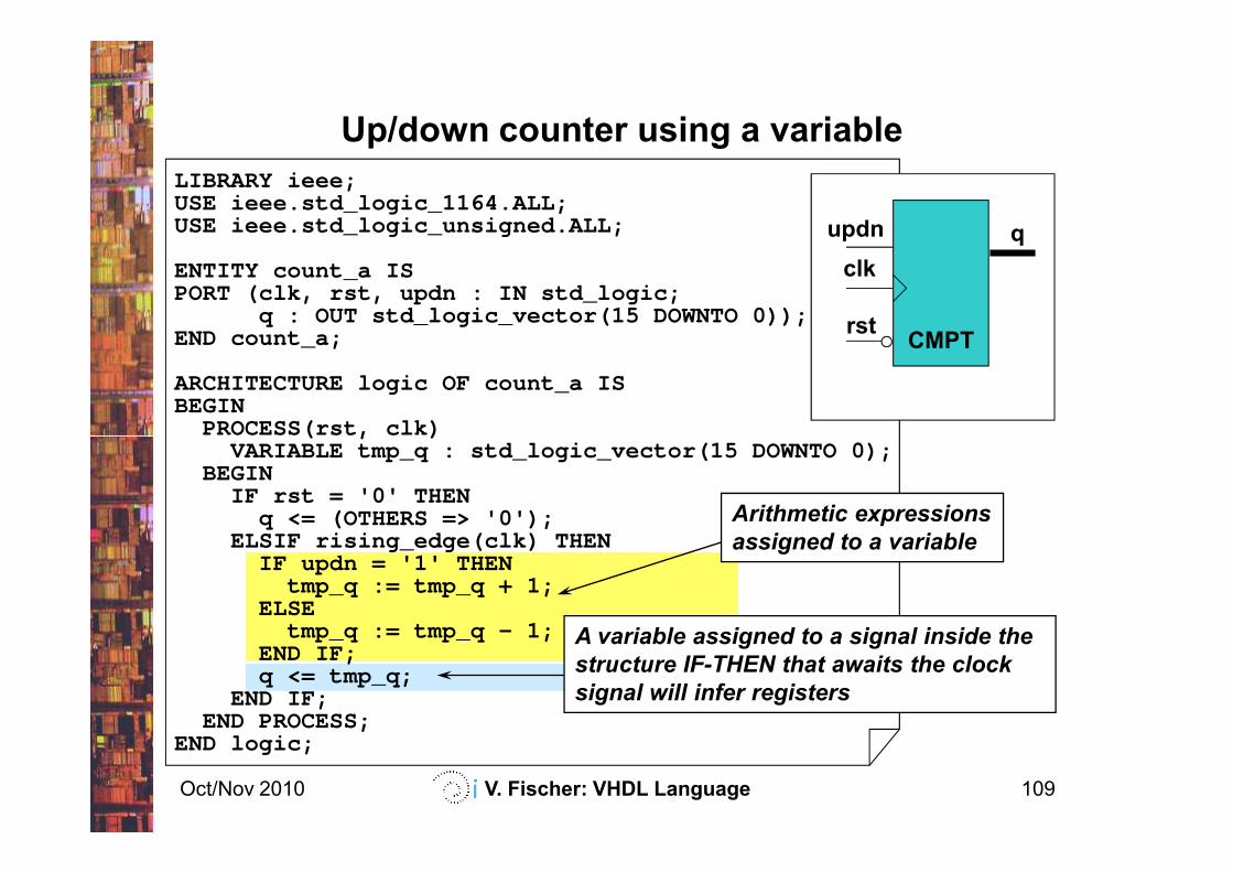
LIBRARY ieee;USE ieee.std_logic_1164.ALL;USE ieee.std_logic_unsigned.ALL;
ENTITY count_a ISPORT (clk, rst, updn : IN std_logic;
q : OUT std_logic_vector(15 DOWNTO 0));END count_a;
ARCHITECTURE logic OF count_a IS BEGIN
PROCESS(rst, clk)
Up/down counter using a variable
Oct/Nov 2010 V. Fischer: VHDL Language 109
A variable assigned to a signal inside the
structure IF-THEN that awaits the clock
signal will infer registers
Arithmetic expressions
assigned to a variable
PROCESS(rst, clk)VARIABLE tmp_q : std_logic_vector(15 DOWNTO 0);
BEGINIF rst = '0' THEN
q <= (OTHERS => '0');ELSIF rising_edge(clk) THEN
IF updn = '1' THENtmp_q := tmp_q + 1;
ELSEtmp_q := tmp_q - 1;
END IF;q <= tmp_q;
END IF;END PROCESS;
END logic;
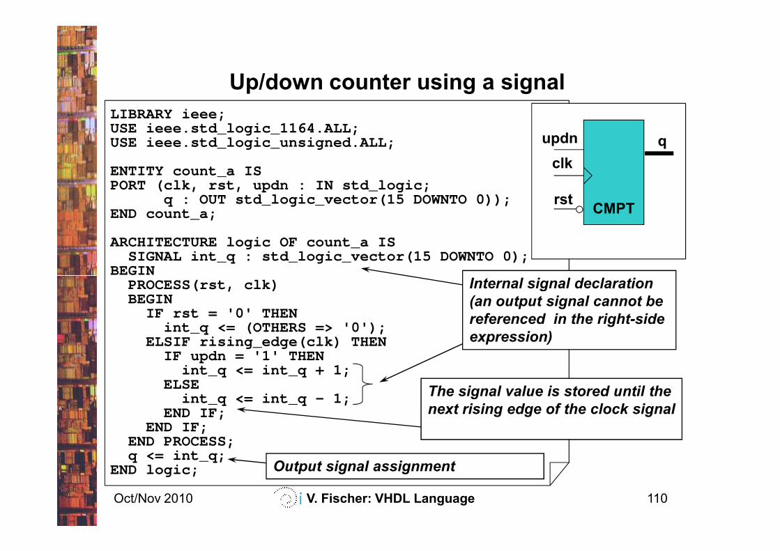
LIBRARY ieee;USE ieee.std_logic_1164.ALL;USE ieee.std_logic_unsigned.ALL;
ENTITY count_a ISPORT (clk, rst, updn : IN std_logic;
q : OUT std_logic_vector(15 DOWNTO 0));END count_a;
ARCHITECTURE logic OF count_a IS SIGNAL int_q : std_logic_vector(15 DOWNTO 0);
BEGINInternal signal declaration
q
clk
rstCMPT
updn
Up/down counter using a signal
Oct/Nov 2010 V. Fischer: VHDL Language 110
BEGINPROCESS(rst, clk)BEGIN
IF rst = '0' THENint_q <= (OTHERS => '0');
ELSIF rising_edge(clk) THENIF updn = '1' THEN
int_q <= int_q + 1;ELSE
int_q <= int_q - 1;END IF;
END IF;END PROCESS;q <= int_q;
END logic;
The signal value is stored until the
next rising edge of the clock signal
Internal signal declaration
(an output signal cannot be
referenced in the right-side
expression)
Output signal assignment
q
clk
rstCMPT
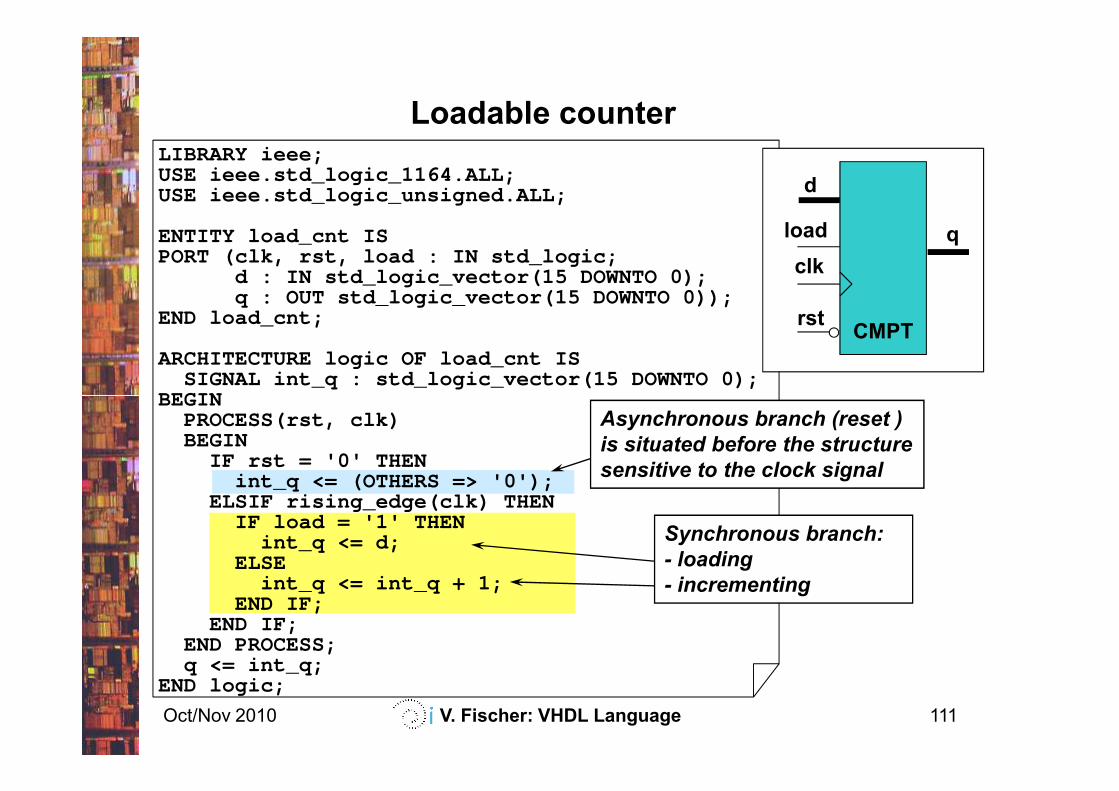
load
d
Loadable counterLIBRARY ieee;USE ieee.std_logic_1164.ALL;USE ieee.std_logic_unsigned.ALL;
ENTITY load_cnt ISPORT (clk, rst, load : IN std_logic;
d : IN std_logic_vector(15 DOWNTO 0);q : OUT std_logic_vector(15 DOWNTO 0));
END load_cnt;
ARCHITECTURE logic OF load_cnt IS SIGNAL int_q : std_logic_vector(15 DOWNTO 0);
BEGIN
Oct/Nov 2010 V. Fischer: VHDL Language 111
Asynchronous branch (reset )
is situated before the structure
sensitive to the clock signal
Synchronous branch:
- loading
- incrementing
BEGINPROCESS(rst, clk)BEGIN
IF rst = '0' THENint_q <= (OTHERS => '0');
ELSIF rising_edge(clk) THENIF load = '1' THEN
int_q <= d;ELSE
int_q <= int_q + 1;END IF;
END IF;END PROCESS;q <= int_q;
END logic;
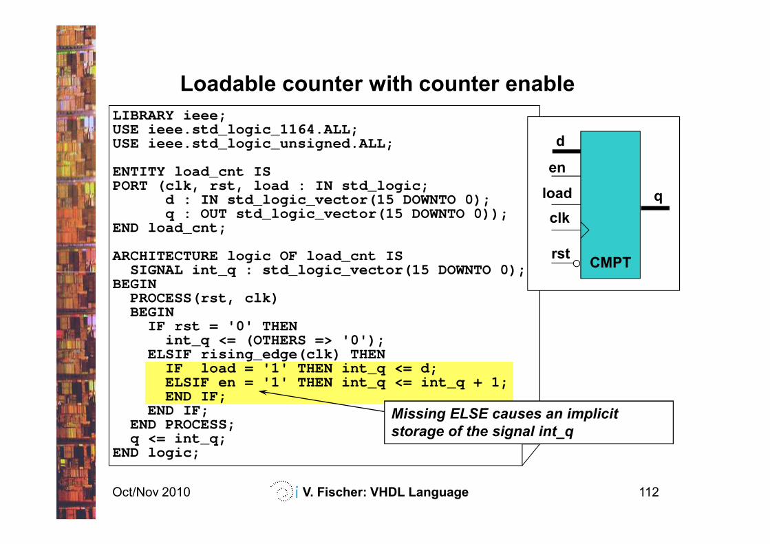
LIBRARY ieee;USE ieee.std_logic_1164.ALL;USE ieee.std_logic_unsigned.ALL;
ENTITY load_cnt ISPORT (clk, rst, load : IN std_logic;
d : IN std_logic_vector(15 DOWNTO 0);q : OUT std_logic_vector(15 DOWNTO 0));
END load_cnt;
ARCHITECTURE logic OF load_cnt IS SIGNAL int_q : std_logic_vector (15 DOWNTO 0);
q
clk
rstCMPT
load
d
en
Loadable counter with counter enable
Oct/Nov 2010 V. Fischer: VHDL Language 112
SIGNAL int_q : std_logic_vector (15 DOWNTO 0);BEGIN
PROCESS(rst, clk)BEGIN
IF rst = '0' THENint_q <= (OTHERS => '0');
ELSIF rising_edge(clk) THENIF load = '1' THEN int_q <= d;ELSIF en = '1' THEN int_q <= int_q + 1;END IF;
END IF;END PROCESS;q <= int_q;
END logic;
Missing ELSE causes an implicit
storage of the signal int_q
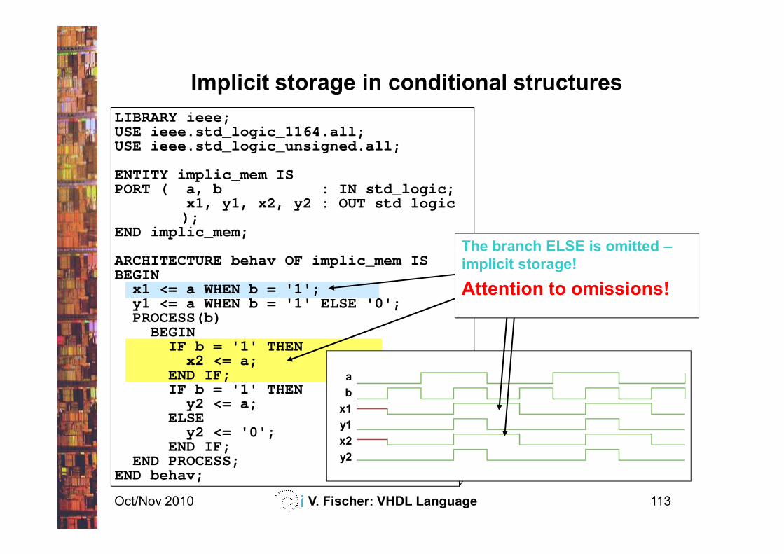
Implicit storage in conditional structures
LIBRARY ieee;USE ieee.std_logic_1164.all;USE ieee.std_logic_unsigned.all;
ENTITY implic_mem ISPORT ( a, b : IN std_logic;
x1, y1, x2, y2 : OUT std_logic);
END implic_mem;
ARCHITECTURE behav OF implic_mem ISBEGIN
The branch ELSE is omitted –
implicit storage!
Oct/Nov 2010 V. Fischer: VHDL Language 113
BEGINx1 <= a WHEN b = '1';y1 <= a WHEN b = '1' ELSE '0';PROCESS(b)
BEGINIF b = '1' THEN
x2 <= a;END IF;IF b = '1' THEN
y2 <= a;ELSE
y2 <= '0';END IF;
END PROCESS;END behav;
a
b
x1
y1
x2
y2
Attention to omissions!
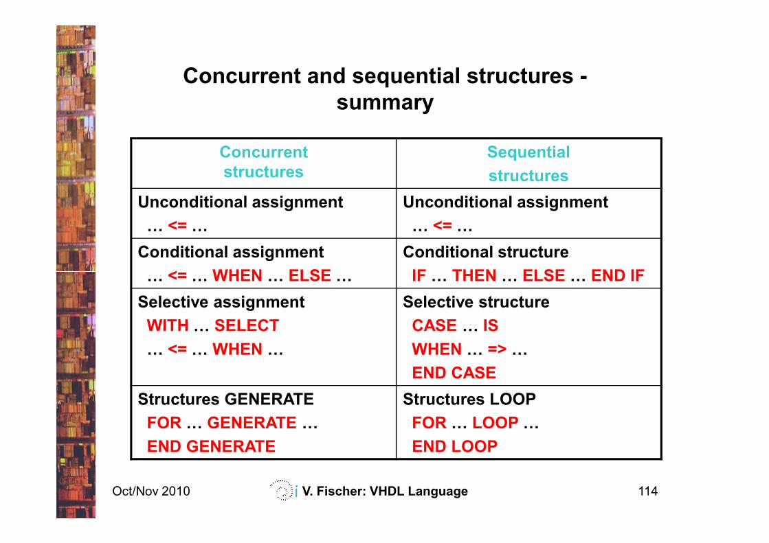
Concurrent and sequential structures -
summary
Concurrent
structures
Sequential
structures
Unconditional assignment
F <= F
Unconditional assignment
F <= F
Conditional assignment
F <= F WHEN F ELSE F
Conditional structure
IF F THEN F ELSE F END IF
Oct/Nov 2010 V. Fischer: VHDL Language 114
F <= F WHEN F ELSE F IF F THEN F ELSE F END IF
Selective assignment
WITH F SELECT
F <= F WHEN F
Selective structure
CASE F IS
WHEN F => F
END CASE
Structures GENERATE
FOR F GENERATE F
END GENERATE
Structures LOOP
FOR F LOOP F
END LOOP
Contents
Introduction
VHDL basics
Concurrent structures
Applications of the concurrent structures
decoders, parity checkers, multiplexers, arithmetic logic units,
comparators, tri-state outputs, bi-directional inputs/outputs
Oct/Nov 2010 V. Fischer: VHDL Language 115
comparators, tri-state outputs, bi-directional inputs/outputs
Sequential structures
Applications of the sequential structures
latches, registers, counters
State machines
Modularity and parameterization of modules
Testbenches
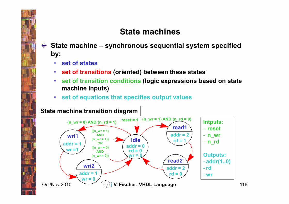
State machines
State machine – synchronous sequential system specified
by:
• set of states
• set of transitions (oriented) between these states
• set of transition conditions (logic expressions based on state
machine inputs)
• set of equations that specifies output values
Oct/Nov 2010 V. Fischer: VHDL Language 116
State machine transition diagram
reset = 1 (n_wr = 1) AND (n_rd = 0)
wri1
addr = 1
wr =1
(n_wr = 0) AND (n_rd = 1)
wri2
addr = 1
wr = 0
idleaddr = 0
rd = 0wr = 0
read1
addr = 2
rd = 1
read2
addr = 2
rd = 0
Intputs:
- reset
- n_wr
- n_rd
Outputs:
- addr(1..0)
- rd
-wr
((n_wr = 1)
AND
(n_wr = 1))
OR
((n_wr = 0)
AND
(n_wr = 0))
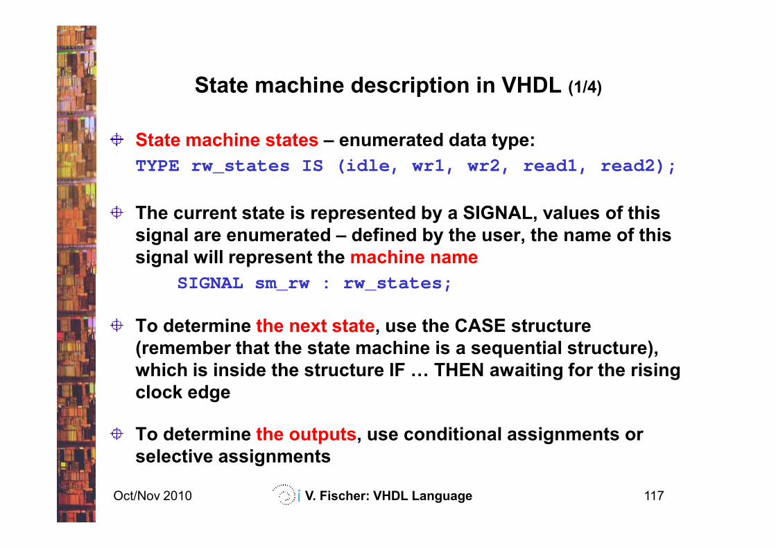
State machine description in VHDL (1/4)
State machine states – enumerated data type:
TYPE rw_states IS (idle, wr1, wr2, read1, read2);
The current state is represented by a SIGNAL, values of this
signal are enumerated – defined by the user, the name of this
signal will represent the machine name
SIGNAL sm_rw : rw_states;
Oct/Nov 2010 V. Fischer: VHDL Language 117
SIGNAL sm_rw : rw_states;
To determine the next state, use the CASE structure
(remember that the state machine is a sequential structure),
which is inside the structure IF F THEN awaiting for the rising
clock edge
To determine the outputs, use conditional assignments or
selective assignments
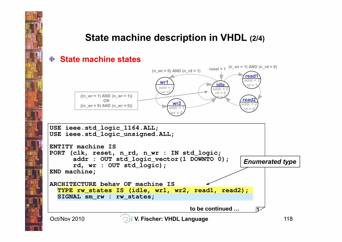
State machine description in VHDL (2/4)
State machine states
wr1addr = 1
wr =1
wr2addr = 1
wr = 0
idleaddr = 0
rd = 0wr = 0
read1addr = 2
rd = 1
read2addr = 2
rd = 0
reset = 1(n_wr = 1) AND (n_rd = 0)
(n_wr = 0) AND (n_rd = 1)
((n_wr = 1) AND (n_wr = 1))
OR
((n_wr = 0) AND (n_wr = 0))
Oct/Nov 2010 V. Fischer: VHDL Language 118
1to be continued F
USE ieee.std_logic_1164.ALL;USE ieee.std_logic_unsigned.ALL;
ENTITY machine ISPORT (clk, reset, n_rd, n_wr : IN std_logic;
addr : OUT std_logic_vector(1 DOWNTO 0);rd, wr : OUT std_logic);
END machine;
ARCHITECTURE behav OF machine ISTYPE rw_states IS (idle, wr1, wr2, read1, read2);SIGNAL sm_rw : rw_states;
Enumerated type
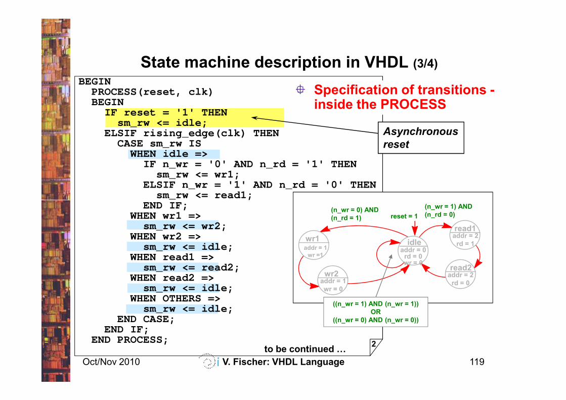
BEGINPROCESS(reset, clk)BEGIN
IF reset = '1' THENsm_rw <= idle;
ELSIF rising_edge(clk) THENCASE sm_rw IS
WHEN idle =>IF n_wr = '0' AND n_rd = '1' THEN
sm_rw <= wr1;ELSIF n_wr = '1' AND n_rd = '0' THEN
sm_rw <= read1;END IF;
State machine description in VHDL (3/4)
Asynchronous
reset
Specification of transitions -inside the PROCESS
Oct/Nov 2010 V. Fischer: VHDL Language 119
sm_rw <= read1;END IF;
WHEN wr1 =>sm_rw <= wr2;
WHEN wr2 =>sm_rw <= idle;
WHEN read1 =>sm_rw <= read2;
WHEN read2 =>sm_rw <= idle;
WHEN OTHERS =>sm_rw <= idle;
END CASE;END IF;
END PROCESS;2
to be continued F
wr1addr = 1
wr =1
wr2addr = 1
wr = 0
idleaddr = 0
rd = 0wr = 0
read1addr = 2
rd = 1
read2addr = 2
rd = 0
(n_wr = 1) AND
(n_rd = 0)(n_wr = 0) AND
(n_rd = 1)
((n_wr = 1) AND (n_wr = 1))
OR
((n_wr = 0) AND (n_wr = 0))
reset = 1
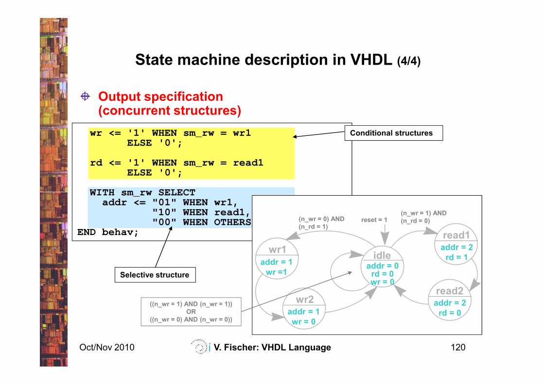
wr <= '1' WHEN sm_rw = wr1ELSE '0';
rd <= '1' WHEN sm_rw = read1ELSE '0';
WITH sm_rw SELECT
State machine description in VHDL (4/4)
Output specification (concurrent structures)
Conditional structures
Oct/Nov 2010 V. Fischer: VHDL Language 120
WITH sm_rw SELECTaddr <= "01" WHEN wr1,
"10" WHEN read1,"00" WHEN OTHERS;
END behav;3
wr1addr = 1
wr =1
wr2addr = 1
wr = 0
idleaddr = 0
rd = 0wr = 0
read1addr = 2
rd = 1
read2addr = 2
rd = 0
Selective structure
reset = 1(n_wr = 1) AND
(n_rd = 0)(n_wr = 0) AND
(n_rd = 1)
((n_wr = 1) AND (n_wr = 1))
OR
((n_wr = 0) AND (n_wr = 0))
q
DFF1
dComb
Next1
n_rd
n_wr
Comb
Out1
Comb
Out2
addr(1)
addr(0)
Critical path! Current state
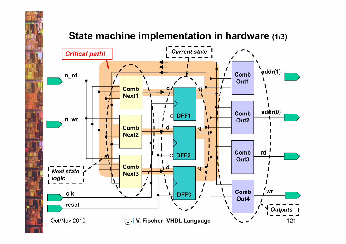
State machine implementation in hardware (1/3)
Oct/Nov 2010 V. Fischer: VHDL Language 121
q
DFF2
d
q
reset
DFF3
d
clk
Comb
Next2
Comb
Next3
n_wr Out2
Comb
Out3
Comb
Out4
rd
wr
Next state
logic
Outputs
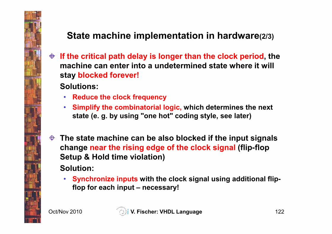
State machine implementation in hardware(2/3)
If the critical path delay is longer than the clock period, the
machine can enter into a undetermined state where it will
stay blocked forever!
Solutions:
• Reduce the clock frequency
• Simplify the combinatorial logic, which determines the next
state (e. g. by using "one hot" coding style, see later)
Oct/Nov 2010 V. Fischer: VHDL Language 122
state (e. g. by using "one hot" coding style, see later)
The state machine can be also blocked if the input signals
change near the rising edge of the clock signal (flip-flop
Setup & Hold time violation)
Solution:
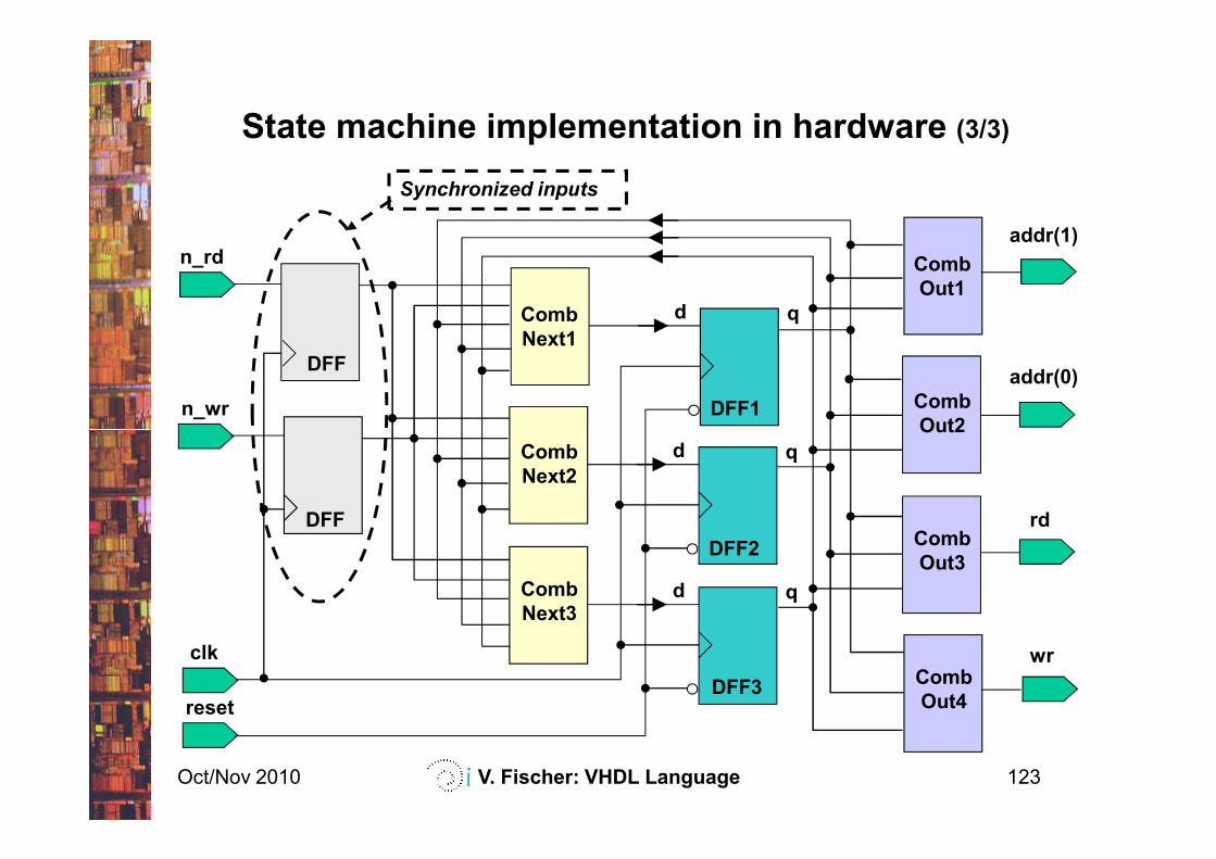
• Synchronize inputs with the clock signal using additional flip-
flop for each input – necessary!
q
DFF1
dComb
Next1
n_rd
n_wr
Comb
Out1
Comb
Out2
addr(1)
addr(0)
State machine implementation in hardware (3/3)
DFF
Synchronized inputs
Oct/Nov 2010 V. Fischer: VHDL Language 123
q
DFF2
d
q
resetDFF3
d
clk
Comb
Next2
Comb
Next3
Out2
Comb
Out3
Comb
Out4
rd
wr
DFF
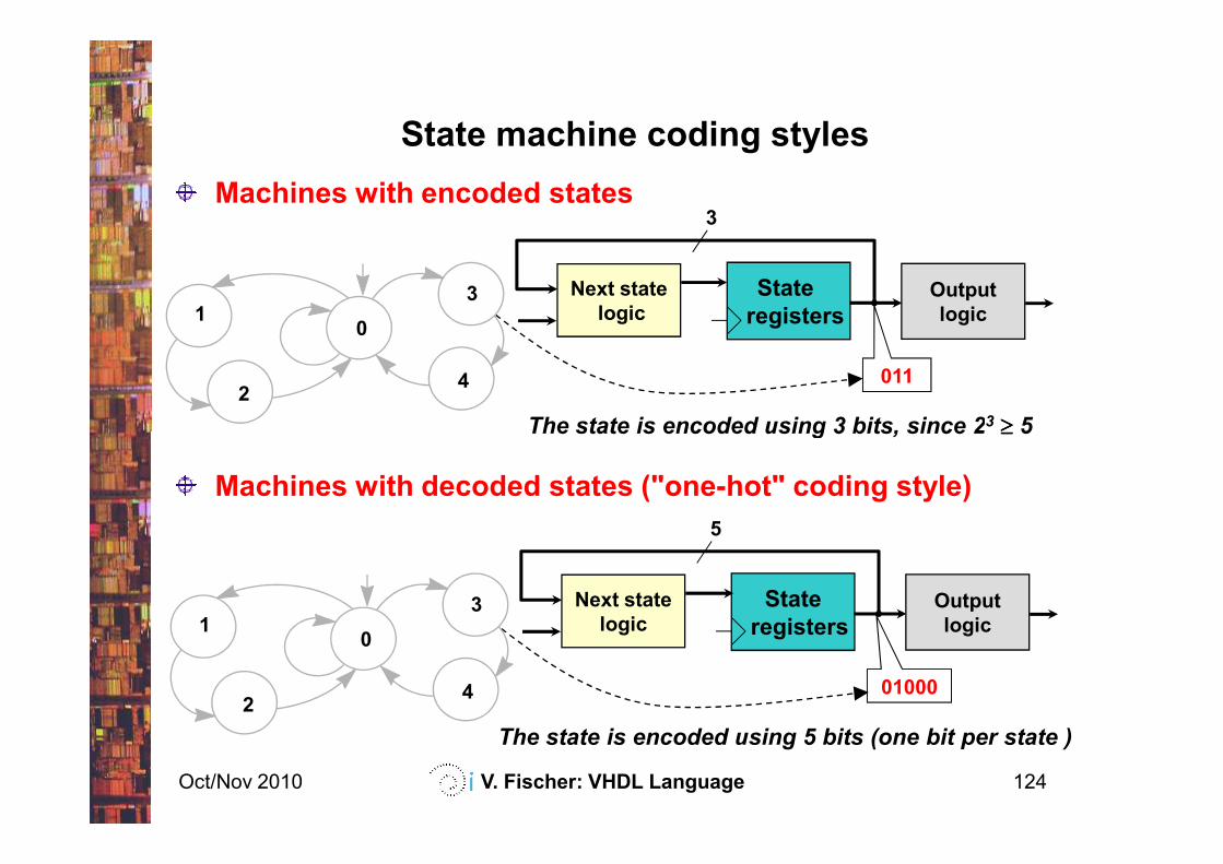
State machine coding styles
Machines with encoded states
Next state
logic
State
registersOutput
logic
3
01
2
3
4 011
The state is encoded using 3 bits, since 23 ≥≥≥≥ 5
Oct/Nov 2010 V. Fischer: VHDL Language 124
Machines with decoded states ("one-hot" coding style)
Next state
logic
State
registersOutput
logic
5
01
2
3
4 01000
The state is encoded using 3 bits, since 2 ≥≥≥≥ 5
The state is encoded using 5 bits (one bit per state )
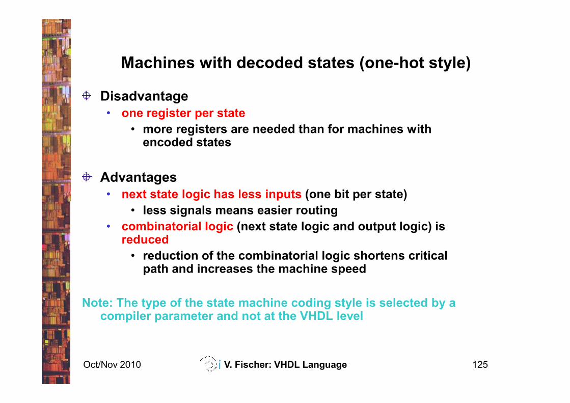
Machines with decoded states (one-hot style)
Disadvantage
• one register per state
• more registers are needed than for machines with encoded states
Advantages
• next state logic has less inputs (one bit per state)
Oct/Nov 2010 V. Fischer: VHDL Language 125
• less signals means easier routing
• combinatorial logic (next state logic and output logic) isreduced
• reduction of the combinatorial logic shortens critical path and increases the machine speed
Note: The type of the state machine coding style is selected by a compiler parameter and not at the VHDL level
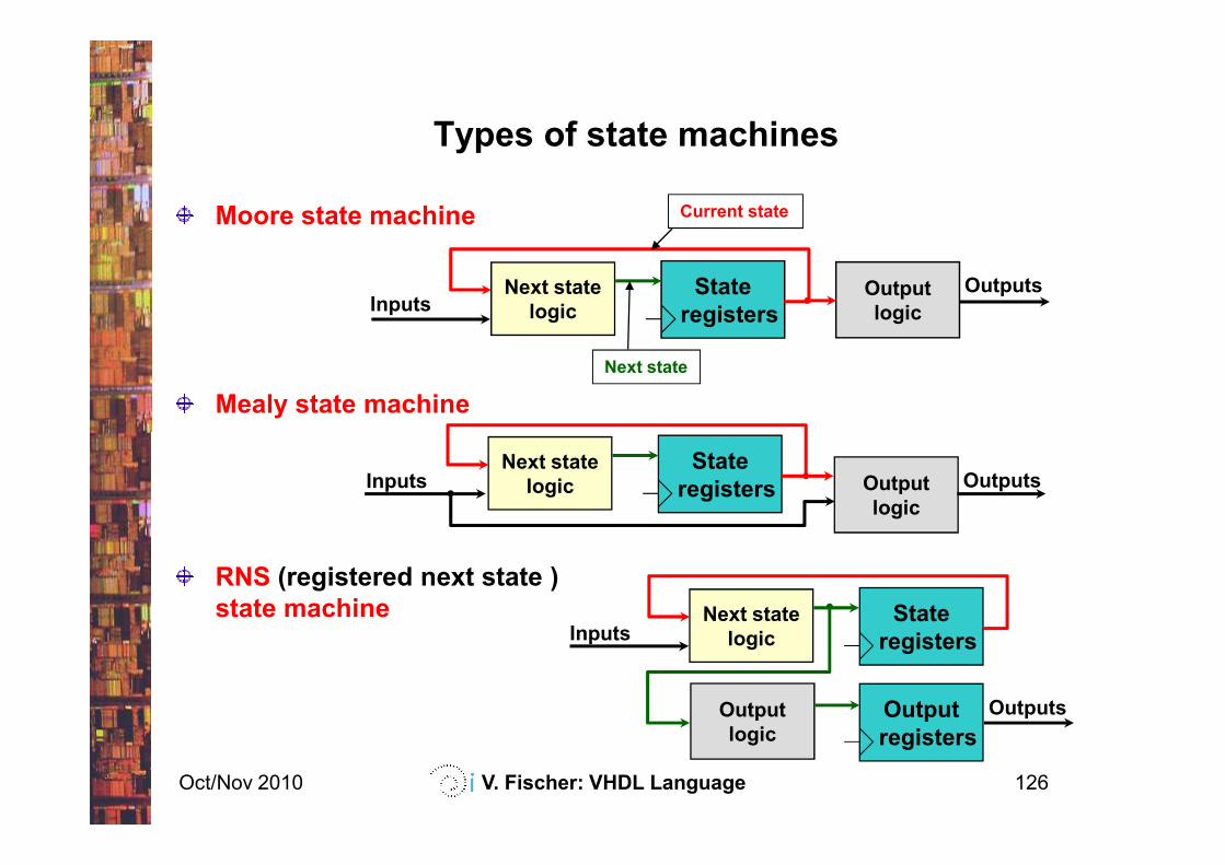
Moore state machine
Mealy state machine
Types of state machines
Next state
logic
State
registersOutput
logic
Current state
Next state
InputsOutputs
Oct/Nov 2010 V. Fischer: VHDL Language 126
RNS (registered next state )
state machine
Next state
logic
State
registers Output
logic
Inputs Outputs
Next state
logic
State
registers
Output
logic
Inputs
Output
registers
Outputs
Principle
• Outputs depend only on the current state
Advantages
• Easy to describe in VHDL (only one CASE structure needed)
• Outputs are valid during the current state
• Output equations are simple, because they depend only on the
Moore state machine
Oct/Nov 2010 V. Fischer: VHDL Language 127
• Output equations are simple, because they depend only on the
current state
• Routing is simpler, because inputs have only one destination (the
next state logic)
Disadvantage
• Combinatorial output signals can contain glitches
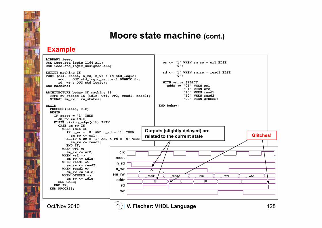
Example
Moore state machine (cont.)
LIBRARY ieee;USE ieee.std_logic_1164.ALL;USE ieee.std_logic_unsigned.ALL;
ENTITY machine ISPORT (clk, reset, n_rd, n_wr : IN std_logic;
addr : OUT std_logic_vector(1 DOWNTO 0);rd, wr : OUT std_logic);
END machine;
ARCHITECTURE behav OF machine ISTYPE rw_states IS (idle, wr1, wr2, read1, read2);SIGNAL sm_rw : rw_states;
BEGINPROCESS(reset, clk)BEGIN
IF r eset = '1' THEN
wr <= '1' WHEN sm_rw = wr1 ELSE'0';
rd <= '1' WHEN sm_rw = read1 ELSE'0';
WITH sm_rw SELECTaddr <= "01" WHEN wr1,
"01" WHEN wr2,"10" WHEN read1,"10" WHEN read2,"00" WHEN OTHERS;
END behav;
Oct/Nov 2010 V. Fischer: VHDL Language 128
BEGINIF r eset = '1' THEN
sm_rw <= idle;ELSIF rising_edge(clk) THEN
CASE sm_rw ISWHEN idle =>
IF n_wr = '0' AND n_rd = '1' THENsm_rw <= wr1;
ELSIF n_wr = '1' AND n_rd = '0' THENsm_rw <= read1;
END IF;WHEN wr1 =>
sm_rw <= wr2;WHEN wr2 =>
sm_rw <= idle;WHEN read1 =>
sm_rw <= read2;WHEN read2 =>
sm_rw <= idle;WHEN OTHERS =>
sm_rw <= idle; END CASE;
END IF;END PROCESS;
clk
reset
n_rd
n_wr
sm_rw
addr
rd
wr
Glitches!Outputs (slightly delayed) are
related to the current state
read1 read2 idle wr1 wr2
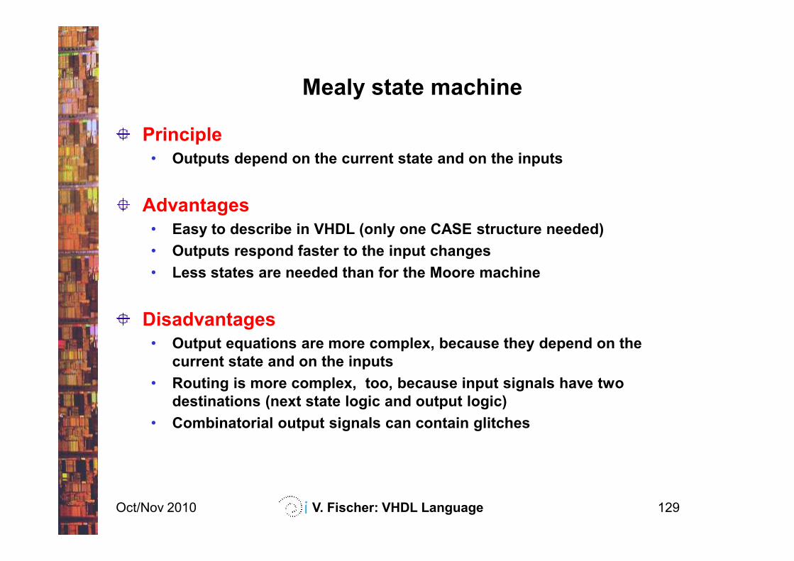
Principle
• Outputs depend on the current state and on the inputs
Advantages
• Easy to describe in VHDL (only one CASE structure needed)
• Outputs respond faster to the input changes
• Less states are needed than for the Moore machine
Mealy state machine
Oct/Nov 2010 V. Fischer: VHDL Language 129
• Less states are needed than for the Moore machine
Disadvantages
• Output equations are more complex, because they depend on the
current state and on the inputs
• Routing is more complex, too, because input signals have two
destinations (next state logic and output logic)
• Combinatorial output signals can contain glitches
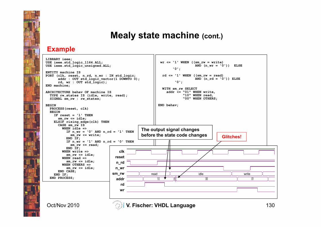
Example
Mealy state machine (cont.)
LIBRARY ieee;USE ieee.std_logic_1164.ALL;USE ieee.std_logic_unsigned.ALL;
ENTITY machine ISPORT (clk, reset, n_rd, n_wr : IN std_logic;
addr : OUT std_logic_vector(1 DOWNTO 0);rd, wr : OUT std_logic);
END machine;
ARCHITECTURE behav OF machine ISTYPE rw_states IS (idle, write, read);SIGNAL sm_rw : rw_states;
BEGINPROCESS(reset, clk)BEGIN
IF r eset = '1' THEN
wr <= '1' WHEN ((sm_rw = write) AND (n_wr = '0')) ELSE
'0';
rd <= '1' WHEN ((sm_rw = read) AND (n_rd = '0')) ELSE
'0';
WITH sm_rw SELECTaddr <= "01" WHEN write,
"10" WHEN read,"00" WHEN OTHERS;
END behav;
Oct/Nov 2010 V. Fischer: VHDL Language 130
BEGINIF r eset = '1' THEN
sm_rw <= idle;ELSIF rising_edge(clk) THEN
CASE sm_rw ISWHEN idle =>
IF n_wr = '0' AND n_rd = '1' THENsm_rw <= write;
END IF;IF n_wr = '1' AND n_rd = '0' THEN
sm_rw <= read;END IF;
WHEN write =>sm_rw <= idle;
WHEN read =>sm_rw <= idle;
WHEN OTHERS =>sm_rw <= idle;
END CASE;END IF;
END PROCESS;
clk
reset
n_rd
n_wr
sm_rw
addr
rd
wr
The output signal changes
before the state code changes Glitches!
read writeidle
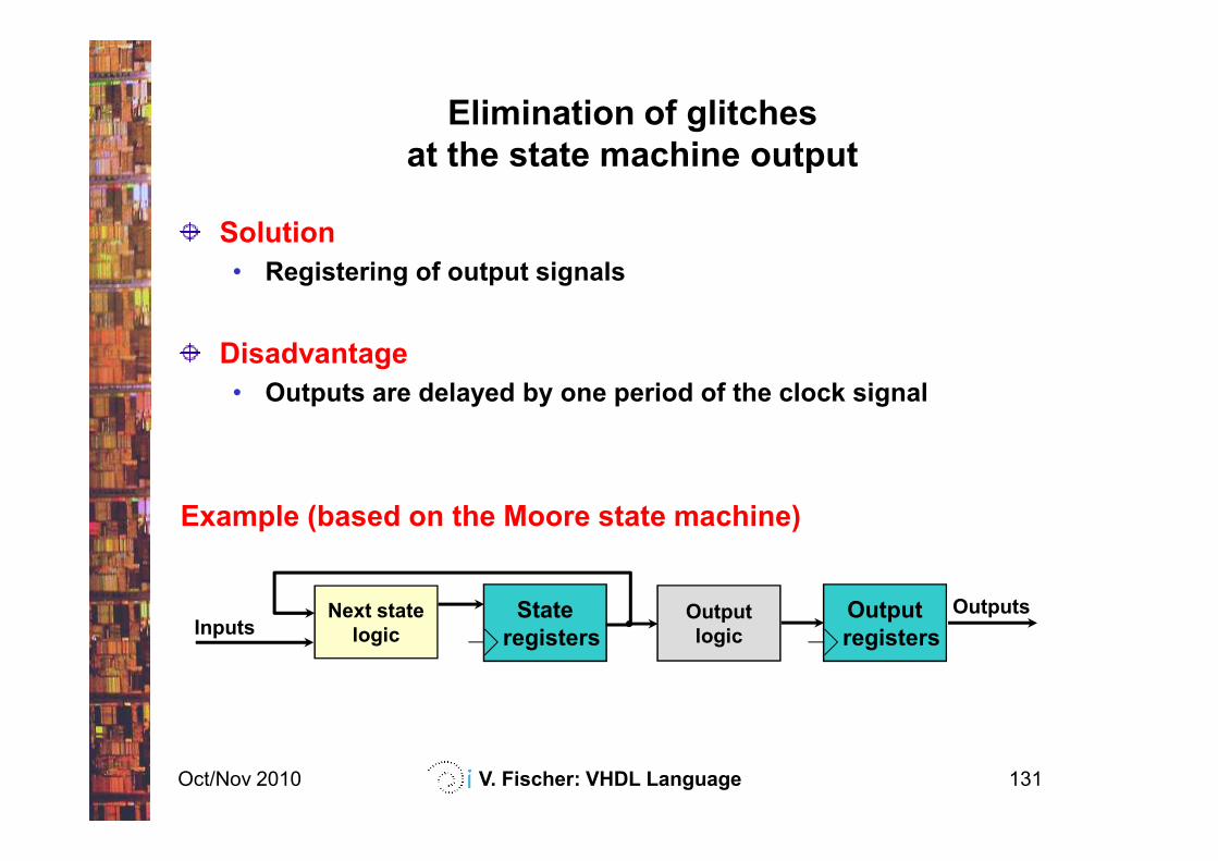
Solution
• Registering of output signals
Disadvantage
• Outputs are delayed by one period of the clock signal
Elimination of glitches
at the state machine output
Oct/Nov 2010 V. Fischer: VHDL Language 131
Example (based on the Moore state machine)
Next state
logic
State
registersOutput
logicInputsOutputsOutput
registers
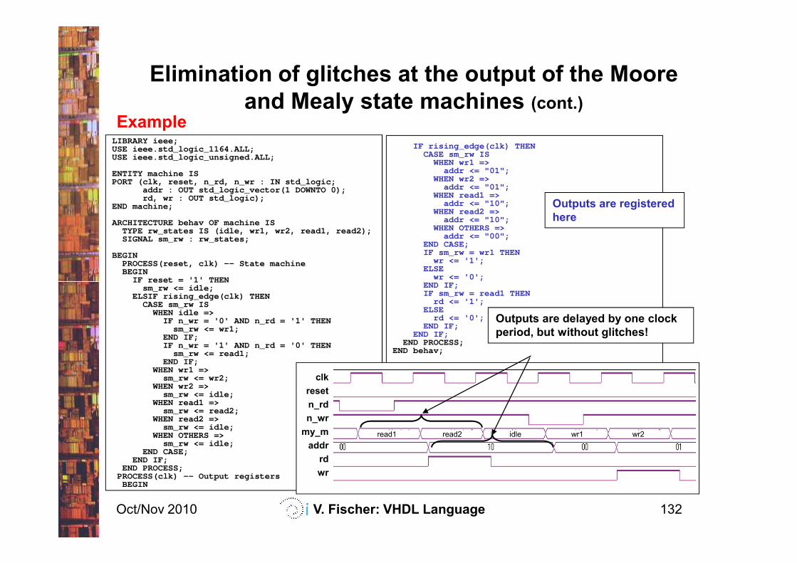
Example
Elimination of glitches at the output of the Moore
and Mealy state machines (cont.)
LIBRARY ieee;USE ieee.std_logic_1164.ALL;USE ieee.std_logic_unsigned.ALL;
ENTITY machine ISPORT (clk, reset, n_rd, n_wr : IN std_logic;
addr : OUT std_logic_vector(1 DOWNTO 0);rd, wr : OUT std_logic);
END machine;
ARCHITECTURE behav OF machine ISTYPE rw_states IS (idle, wr1, wr2, read1, read2);SIGNAL sm_rw : rw_states;
BEGINPROCESS(reset, clk) -- State machineBEGIN
IF r eset = '1' THEN
IF rising_edge(clk) THENCASE sm_rw IS
WHEN wr1 =>addr <= "01";
WHEN wr2 =>addr <= "01";
WHEN read1 =>addr <= "10";
WHEN read2 =>addr <= "10";
WHEN OTHERS =>addr <= "00";
END CASE;IF sm_rw = wr1 THEN
wr <= '1';ELSE
wr <= '0';END IF;
Outputs are registered
here
Oct/Nov 2010 V. Fischer: VHDL Language 132
IF r eset = '1' THENsm_rw <= idle;
ELSIF rising_edge(clk) THENCASE sm_rw IS
WHEN idle =>IF n_wr = '0' AND n_rd = '1' THEN
sm_rw <= wr1;END IF;IF n_wr = '1' AND n_rd = '0' THEN
sm_rw <= read1;END IF;
WHEN wr1 =>sm_rw <= wr2;
WHEN wr2 =>sm_rw <= idle;
WHEN read1 =>sm_rw <= read2;
WHEN read2 =>sm_rw <= idle;
WHEN OTHERS =>sm_rw <= idle;
END CASE;END IF;
END PROCESS;PROCESS(clk) -- Output registers
BEGIN
wr <= '0';END IF;IF sm_rw = read1 THEN
rd <= '1';ELSE
rd <= '0';END IF;
END IF;END PROCESS;
END behav;
clk
reset
n_rd
n_wr
my_m
addr
rd
wr
Outputs are delayed by one clock
period, but without glitches!
read1 read2 idle wr1 wr2
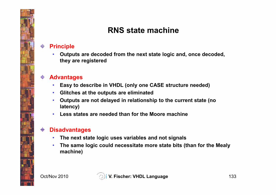
Principle
• Outputs are decoded from the next state logic and, once decoded,
they are registered
Advantages
• Easy to describe in VHDL (only one CASE structure needed)
• Glitches at the outputs are eliminated
• Outputs are not delayed in relationship to the current state (no
RNS state machine
Oct/Nov 2010 V. Fischer: VHDL Language 133
• Outputs are not delayed in relationship to the current state (no
latency)
• Less states are needed than for the Moore machine
Disadvantages
• The next state logic uses variables and not signals
• The same logic could necessitate more state bits (than for the Mealy
machine)
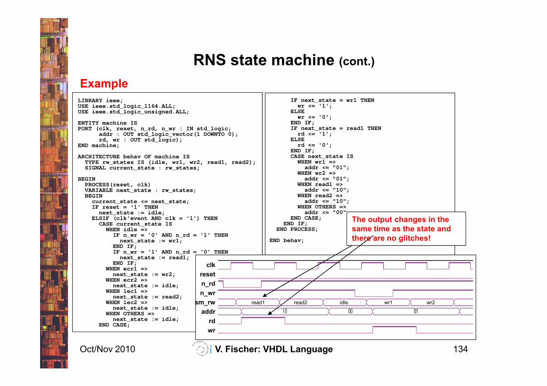
Example
RNS state machine (cont.)
LIBRARY ieee;USE ieee.std_logic_1164.ALL;USE ieee.std_logic_unsigned.ALL;
ENTITY machine ISPORT (clk, reset, n_rd, n_wr : IN std_logic;
addr : OUT std_logic_vector(1 DOWNTO 0);rd, wr : OUT std_logic);
END machine;
ARCHITECTURE behav OF machine ISTYPE rw_states IS (idle, wr1, wr2, read1, read2);SIGNAL current_state : rw_states;
BEGINPROCESS(reset, clk)VARIABLE next _state : rw_ state s;BEGIN
IF next_state = wr1 THENwr <= '1';
ELSEwr <= '0';
END IF;IF next_state = read1 THEN
rd <= '1';ELSE
rd <= '0';END IF;CASE next_state IS
WHEN wr1 =>addr <= "01";
WHEN wr2 =>addr <= "01";
WHEN read1 =>addr <= "10";
WHEN read 2 =>
Oct/Nov 2010 V. Fischer: VHDL Language 134
VARIABLE next _state : rw_ state s;BEGIN
current_state <= next_state;IF reset = '1' THEN
next_state := idle;ELSIF (clk'event AND clk = '1') THEN
CASE current_state ISWHEN idle =>
IF n_wr = '0' AND n_rd = '1' THENnext_state := wr1;
END IF;IF n_wr = '1' AND n_rd = '0' THEN
next_state := read1;END IF;
WHEN ecr1 =>next_state := wr2;
WHEN ecr2 =>next_state := idle;
WHEN lec1 =>next_state := read2;
WHEN lec2 =>next_state := idle;
WHEN OTHERS =>next_state := idle;
END CASE;
addr <= "10";WHEN read 2 =>
addr <= "10";WHEN OTHERS =>
addr <= "00";END CASE;
END IF;END PROCESS;
END behav;
clk
reset
n_rd
n_wr
sm_rw
addr
rd
wr
The output changes in the
same time as the state and
there are no glitches!
read1 read2 idle wr1 wr2
Contents
Introduction
VHDL basics
Concurrent structures
Applications of the concurrent structures
decoders, parity checkers, multiplexers, arithmetic logic units,
tri-state outputs, bi-directional inputs/outputs
Oct/Nov 2010 V. Fischer: VHDL Language 135
tri-state outputs, bi-directional inputs/outputs
Sequential structures
Applications of the sequential structures
latches, registers, counters
State machines
Modularity and parameterization of modules
Testbenches
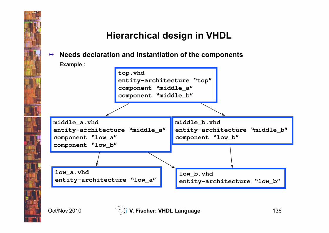
Hierarchical design in VHDL
Needs declaration and instantiation of the components
Example :
top.vhdentity-architecture “top”component “middle_a”component “middle_b”
Oct/Nov 2010 V. Fischer: VHDL Language 136
middle_a.vhdentity-architecture “middle_a”component “low_a”component “low_b”
middle_b.vhdentity-architecture “middle_b”component “low_b”
low_a.vhdentity-architecture “low_a”
low_b.vhdentity-architecture “low_b”
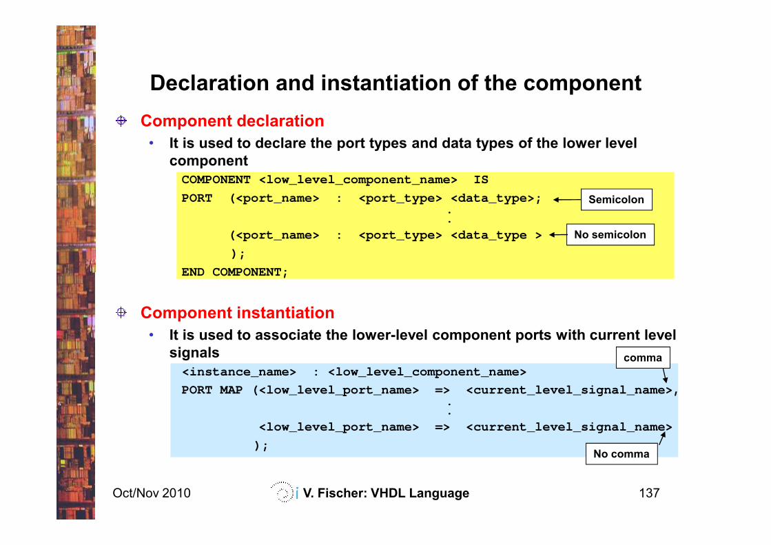
Declaration and instantiation of the component
Semicolon
No semicolon
Component declaration
• It is used to declare the port types and data types of the lower level
component
COMPONENT <low_level_component_name> IS
PORT ( <port_name> : <port_type> <data_type>;..
( <port_name> : <port_type> <data_type >
);
END COMPONENT;
Oct/Nov 2010 V. Fischer: VHDL Language 137
No comma
comma
END COMPONENT;
Component instantiation
• It is used to associate the lower-level component ports with current level
signals
<instance_name> : <low_level_component_name>
PORT MAP (<low_level_port_name> => <current_level_signal_name>,..
<low_level_port_name> => <current_level_signal_name>
);
Each team member can design modules (components) independently (in separated files)
The components can be reused later by other team members
Hierarchical design enhances modularity and portability of the projects
Advantages of the hierarchical design
Oct/Nov 2010 V. Fischer: VHDL Language 138
projects
Hierarchical design simplifies the possibility to implement and to test various versions of the same module
Compilation options can be applied globally or per component - the design can be locally optimized!
More hierarchical levels mean more flexibility!
Design modularity optimization for the placement and routing (P/R) - searching the optimum size of the module
• If the modules are too small, the placement and routing is not easier (it is the same as for the one-module design)
• If the modules are too big, the placement and routing can be even more difficult
Two modularity approaches
Oct/Nov 2010 V. Fischer: VHDL Language 139
• Optimum module size for the FPGAs : 40 – 60 Logic Cells
Design modularity optimization for the performance –searching modules with optimal cost (area) and performance (speed)
• Area-critical and speed-critical modules can be separated and optimized independently
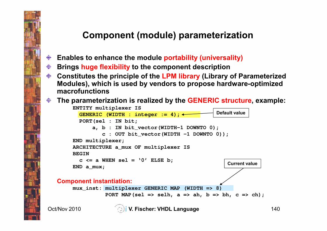
Component (module) parameterization
Default value
Enables to enhance the module portability (universality)
Brings huge flexibility to the component description
Constitutes the principle of the LPM library (Library of Parameterized Modules), which is used by vendors to propose hardware-optimized macrofunctions
The parameterization is realized by the GENERIC structure, example:ENTITY multiplexer IS
GENERIC (WIDTH : integer := 4);
Oct/Nov 2010 V. Fischer: VHDL Language 140
Current value
GENERIC (WIDTH : integer := 4);PORT(sel : IN bit;
a, b : IN bit_vector(WIDTH-1 DOWNTO 0);c : OUT bit_vector(WIDTH -1 DOWNTO 0));
END multiplexer;ARCHITECTURE a_mux OF multiplexer ISBEGIN
c <= a WHEN sel = ‘0’ ELSE b;END a_mux;
Component instantiation:mux_inst: multiplexer GENERIC MAP (WIDTH => 8)
PORT MAP(sel => selh, a => ah, b => bh, c => ch);
Contents
Introduction
VHDL basics
Concurrent structures
Applications of the concurrent structures
decoders, parity checkers, multiplexers, arithmetic logic units,
tri-state outputs, bi-directional inputs/outputs
Oct/Nov 2010 V. Fischer: VHDL Language 141
tri-state outputs, bi-directional inputs/outputs
Sequential structures
Applications of the sequential structures
latches, registers, counters
State machines
Modularity and parameterization of modules
Testbenches
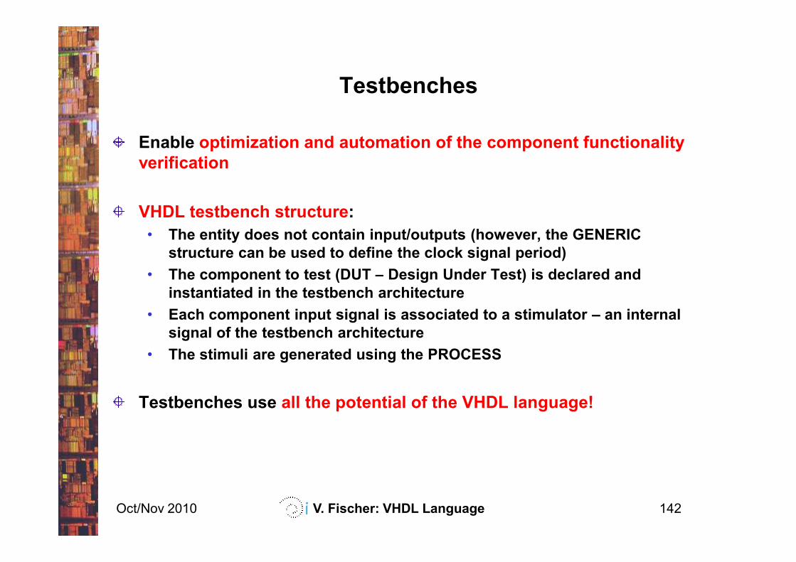
Enable optimization and automation of the component functionality
verification
VHDL testbench structure:
• The entity does not contain input/outputs (however, the GENERIC
structure can be used to define the clock signal period)
• The component to test (DUT – Design Under Test) is declared and
Testbenches
Oct/Nov 2010 V. Fischer: VHDL Language 142
• The component to test (DUT – Design Under Test) is declared and
instantiated in the testbench architecture
• Each component input signal is associated to a stimulator – an internal
signal of the testbench architecture
• The stimuli are generated using the PROCESS
Testbenches use all the potential of the VHDL language!
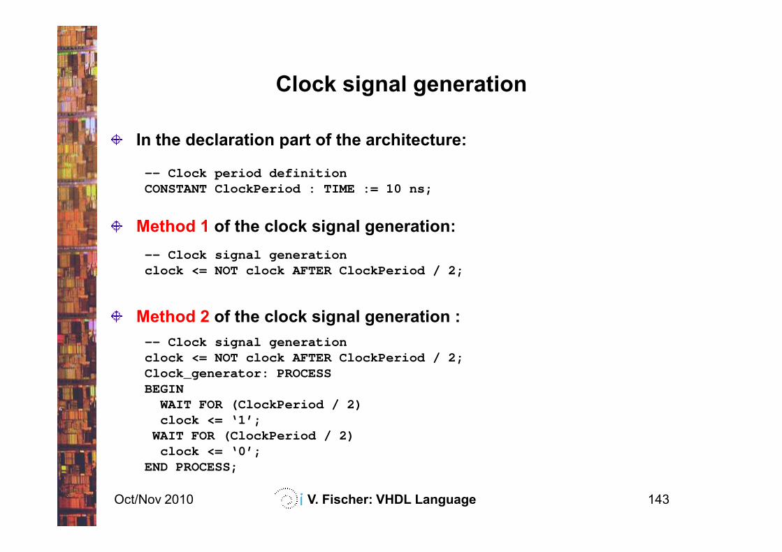
In the declaration part of the architecture:
-- Clock period definitionCONSTANT ClockPeriod : TIME := 10 ns;
Method 1 of the clock signal generation:
-- Clock signal generationclock <= NOT clock AFTER ClockPeriod / 2;
Clock signal generation
Oct/Nov 2010 V. Fischer: VHDL Language 143
clock <= NOT clock AFTER ClockPeriod / 2;
Method 2 of the clock signal generation :
-- Clock signal generationclock <= NOT clock AFTER ClockPeriod / 2;Clock_generator: PROCESSBEGIN
WAIT FOR (ClockPeriod / 2)clock <= ‘1’;
WAIT FOR (ClockPeriod / 2)clock <= ‘0’;
END PROCESS;
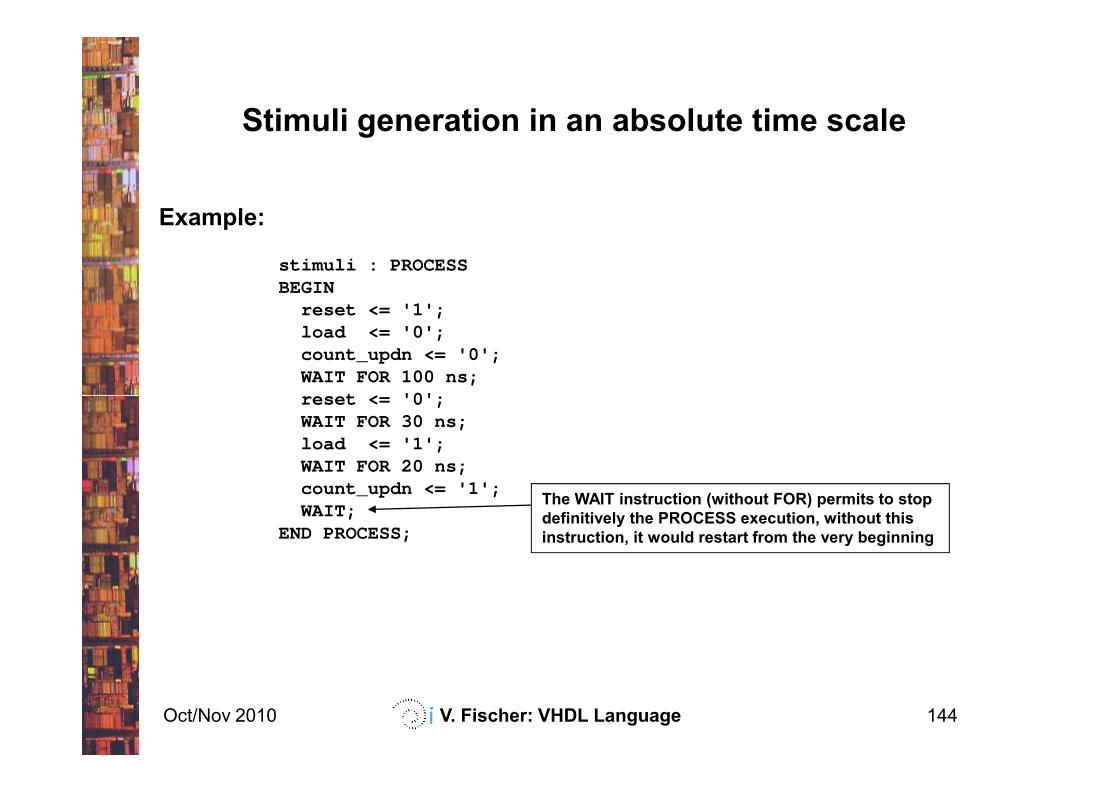
Example:
stimuli : PROCESSBEGIN
reset <= '1';load <= '0';count_updn <= '0';WAIT FOR 100 ns;reset <= '0';
Stimuli generation in an absolute time scale
Oct/Nov 2010 V. Fischer: VHDL Language 144
reset <= '0';WAIT FOR 30 ns;load <= '1';WAIT FOR 20 ns;count_updn <= '1';WAIT;
END PROCESS;
The WAIT instruction (without FOR) permits to stop
definitively the PROCESS execution, without this
instruction, it would restart from the very beginning
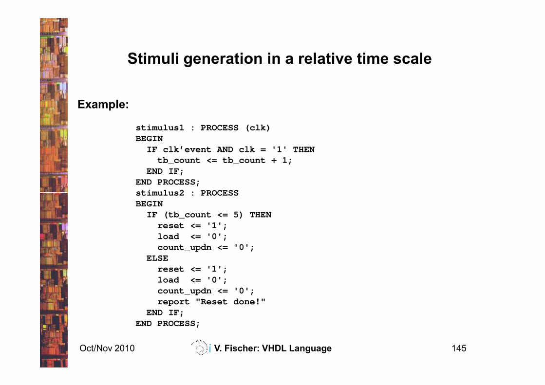
Example:
stimulus1 : PROCESS (clk)BEGIN
IF clk’event AND clk = '1' THENtb_count <= tb_count + 1;
END IF;END PROCESS;stimulus2 : PROCESS
Stimuli generation in a relative time scale
Oct/Nov 2010 V. Fischer: VHDL Language 145
stimulus2 : PROCESSBEGIN
IF (tb_count <= 5) THENreset <= '1';load <= '0';count_updn <= '0';
ELSEreset <= '1';load <= '0';count_updn <= '0';report "Reset done!"
END IF;END PROCESS;
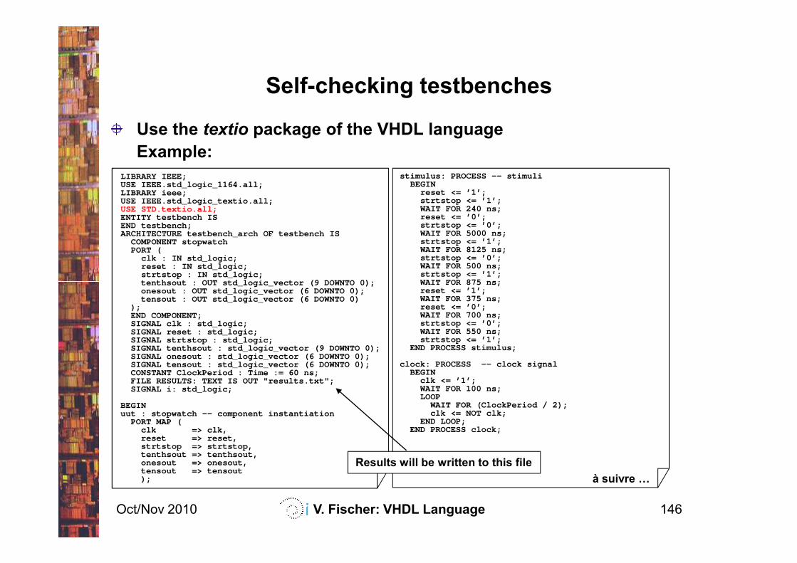
Use the textio package of the VHDL language
Example:
Self-checking testbenches
LIBRARY IEEE;USE IEEE.std_logic_1164.all;LIBRARY ieee;USE IEEE.std_logic_textio.all;USE STD.textio.all;ENTITY testbench ISEND testbench;ARCHITECTURE testbench_arch OF testbench IS
COMPONENT stopwatchPORT (
clk : IN std_logic;reset : IN std_logic;strtstop : IN std_logic;tenthsout : OUT std_logic_vector (9 DOWNTO 0);
stimulus: PROCESS -- stimuliBEGIN
reset <= ’1’;strtstop <= ’1’;WAIT FOR 240 ns;reset <= ’0’;strtstop <= ’0’;WAIT FOR 5000 ns;strtstop <= ’1’;WAIT FOR 8125 ns;strtstop <= ’0’;WAIT FOR 500 ns;strtstop <= ’1’;WAIT FOR 875 ns;
Oct/Nov 2010 V. Fischer: VHDL Language 146
tenthsout : OUT std_logic_vector (9 DOWNTO 0);onesout : OUT std_logic_vector (6 DOWNTO 0);tensout : OUT std_logic_vector (6 DOWNTO 0)
);END COMPONENT;SIGNAL clk : std_logic;SIGNAL reset : std_logic;SIGNAL strtstop : std_logic;SIGNAL tenthsout : std_logic_vector (9 DOWNTO 0);SIGNAL onesout : std_logic_vector (6 DOWNTO 0);SIGNAL tensout : std_logic_vector (6 DOWNTO 0);CONSTANT ClockPeriod : Time := 60 ns;FILE RESULTS: TEXT IS OUT "results.txt";SIGNAL i: std_logic;
BEGINuut : stopwatch –- component instantiation
PORT MAP (clk => clk,reset => reset,strtstop => strtstop,tenthsout => tenthsout,onesout => onesout,tensout => tensout);
WAIT FOR 875 ns;reset <= ’1’;WAIT FOR 375 ns;reset <= ’0’;WAIT FOR 700 ns;strtstop <= ’0’;WAIT FOR 550 ns;strtstop <= ’1’;
END PROCESS stimulus;
clock: PROCESS -- clock signalBEGIN
clk <= ’1’;WAIT FOR 100 ns;LOOP
WAIT FOR (ClockPeriod / 2);clk <= NOT clk;
END LOOP;END PROCESS clock;
à suivre F
Results will be written to this file
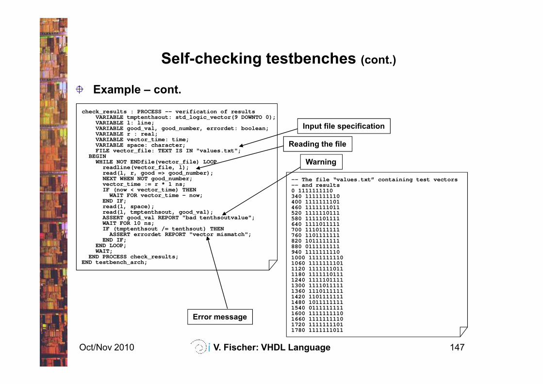
Example – cont.
Self-checking testbenches (cont.)
check_results : PROCESS -- verification of resultsVARIABLE tmptenthsout: std_logic_vector(9 DOWNTO 0);VARIABLE l: line;VARIABLE good_val, good_number, errordet: boolean;VARIABLE r : real;VARIABLE vector_time: time;VARIABLE space: character;FILE vector_file: TEXT IS IN "values.txt";
BEGINWHILE NOT ENDfile(vector_file) LOOP
readline(vector_file, l);read(l, r, good => good_number);NEXT WHEN NOT good_number;vector_time := r * 1 ns;IF (now < vector_time) THEN
-- The file “values.txt” containing test vectors -- and results0 1111111110
Warning
Reading the file
Input file specification
Oct/Nov 2010 V. Fischer: VHDL Language 147
IF (now < vector_time) THENWAIT FOR vector_time - now;
END IF;read(l, space);read(l, tmptenthsout, good_val);ASSERT good_val REPORT "bad tenthsoutvalue";WAIT FOR 10 ns;IF (tmptenthsout /= tenthsout) THEN
ASSERT errordet REPORT "vector mismatch";END IF;
END LOOP;WAIT;
END PROCESS check_results;END testbench_arch;
0 1111111110340 1111111110400 1111111101460 1111111011520 1111110111580 1111101111640 1111011111700 1110111111760 1101111111820 1011111111880 0111111111940 11111111101000 11111111101060 11111111011120 11111110111180 11111101111240 11111011111300 11110111111360 11101111111420 11011111111480 10111111111540 01111111111600 11111111101660 11111111101720 11111111011780 1111111011
Error message