Embed Size (px)
DESCRIPTION
modelling of mechanical system
Citation preview
Course: Modelling and Simulations of Mechanical Systems Master Degree in Mechatronics Engineering
University of Trento Course Project Report
Design of a Mobile Telepresence Device
Report
<Solomon Genene Gudeta>
<Tesfaye Asmera Mengesha>
<Wendwossen Bellete Bedada>
<Mehari Kebede Tesfay>
<August 30, 2013>
Modelling and Simualtion of Mechanical Systems – Master Degree Course
Report:Design of a Telepresence Device.pdf 1
1 Introduction
The mobile telepresence device implements the
three wheel inverted pendulum mechanism. The
pendulum is anchored to a base platform that has a
wheel mounted on each side and one small wheel on
the rear end of the base. The motor drives each front
wheel independently, while the rear wheel is freely
movable. The system has a body that supports the
screen and camera at the desired height level. To
make the conversation smooth and real, the handler
(screen, camera) has been made to have some degree
of mov’t (rotation).
In this project we have designed a new device which
is different to the one available in the market.
Started by building a prototype, determining
components and their specifications, we determined
QFD which is the basis for the determination of
target parameters. The kinematic and dynamic
analyses are studied for the simplified version of the
device neglecting some forces. To make the device
robust to external disturbances we have carried out
the controller design.
The device is basically limited to indoor
environments with small slope surfaces.
2 Customer requirements
After discussing on the customer requirements
given, we have considered the followings:-
1. Handling and maneuverable: The ability of the
system to move in narrow space and change
direction.
2. Stable (robust): stable with respect to external
disturbances and must be safe for the user-
interface device.
3. Controllable: The ability of the robot to move in
the required direction with desired speed.
4. Easy to control at low speed: ability of robot to
move with constant speed or stand still to
record panoramas and watch the scene
5. Carry user interface at 1m or adjustable: It is
required that the height at which the user
interface mounted is adjustable and sufficiently
high for communicating.
6. Dynamic performance: It is expected that our
robot must have the same speed and stability to
walking man. An average walking speed for a
man is 1.15 m/sec.
7. Compactness: describes the amount of space
taken by the robot.
8. Autonomous: collision avoidance, path
detection and independent battery source.
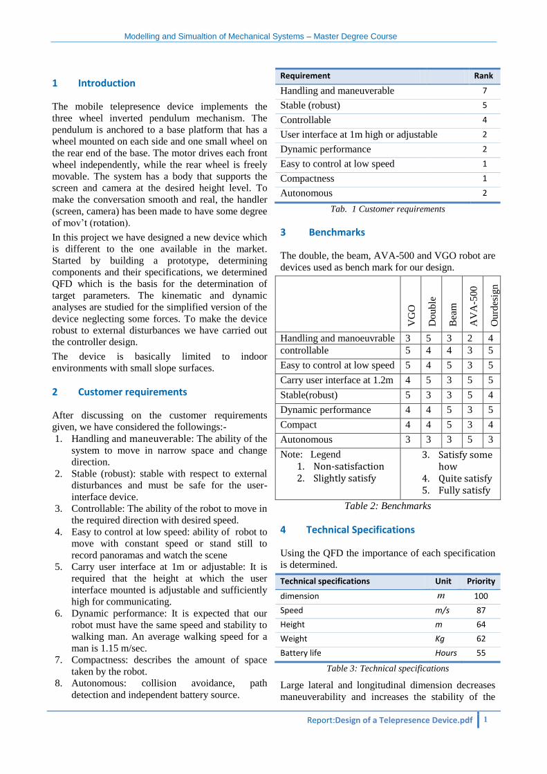
Requirement Rank
Handling and maneuverable 7
Stable (robust) 5
Controllable 4
User interface at 1m high or adjustable 2
Dynamic performance 2
Easy to control at low speed 1
Compactness 1
Autonomous 2
Tab. 1 Customer requirements
3 Benchmarks
The double, the beam, AVA-500 and VGO robot are
devices used as bench mark for our design.
VG
O
Double
Bea
m
AV
A-5
00
Ourd
esig
n
Handling and manoeuvrable 3 5 3 2 4
controllable 5 4 4 3 5
Easy to control at low speed 5 4 5 3 5
Carry user interface at 1.2m 4 5 3 5 5
Stable(robust) 5 3 3 5 4
Dynamic performance 4 4 5 3 5
Compact 4 4 5 3 4
Autonomous 3 3 3 5 3
Note: Legend
1. Non-satisfaction 2. Slightly satisfy
3. Satisfy some how
4. Quite satisfy 5. Fully satisfy
Table 2: Benchmarks
4 Technical Specifications
Using the QFD the importance of each specification
is determined.
Technical specifications Unit Priority
dimension m 100
Speed m/s
87
Height m 64
Weight Kg 62
Battery life Hours 55
Table 3: Technical specifications
Large lateral and longitudinal dimension decreases
maneuverability and increases the stability of the
Modelling and Simualtion of Mechanical Systems – Master Degree Course
Report:Design of a Telepresence Device.pdf 2
system. Those dimensions are the highest in terms of
satisfying customer requirement.
Speed of the robot measures how well the dynamic
requirement is achieved. The ability to achieve
desired speed also increases controllability.
The height of the bar improves the visibility of user
interface screen mounted on it whereas degrading
the compactness and maneuverability.
Weight of the system decreases compactness and
dynamic performance of the system.
Higher battery life is achieved at a cost of size of
system (compactness) and handling difficulties. On
the other hand it makes the robot autonomous with
the capability of operating on its own power without
direct power supply.
5 Targets/Goals and parameters
Basing on the technical priority of the technical
specification derived from QFD the range of
parameters is determined.
Technical specifications Unit Min Value
Max Value
Longitudinal length m 0.2 0.5
Lateral length m 0.15 0.25
Speed m/s 0.8 3
Mass Kg 5 10
Height m 1 1.5
Battery life Hours 5 -
Table 4.Target values
The desired value is extracted based on the table
above and the benchmark table. Attention is given to
the overall performance of the system.
Technical specifications Unit Desired value
Lateral length m 0.35
Longitudinal length m 0.17
Speed m/s
1.15
Height m 1.5
Mass Kg 5
Battery life Hours 6
Table 5.Desired values
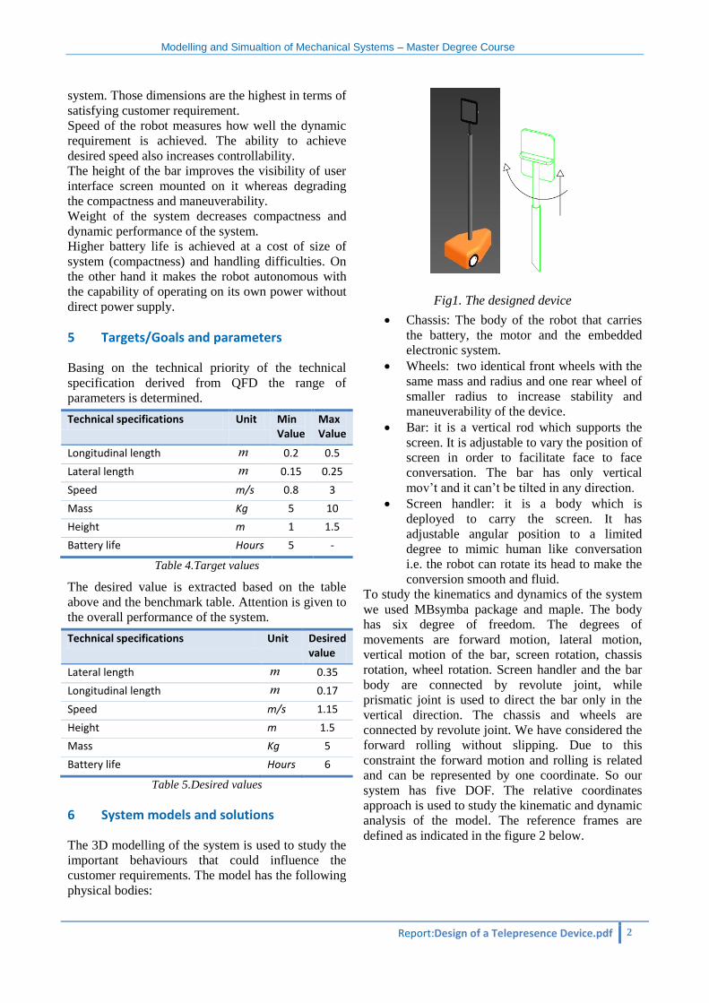
6 System models and solutions
The 3D modelling of the system is used to study the
important behaviours that could influence the
customer requirements. The model has the following
physical bodies:
Fig1. The designed device
Chassis: The body of the robot that carries
the battery, the motor and the embedded
electronic system.
Wheels: two identical front wheels with the
same mass and radius and one rear wheel of
smaller radius to increase stability and
maneuverability of the device.
Bar: it is a vertical rod which supports the
screen. It is adjustable to vary the position of
screen in order to facilitate face to face
conversation. The bar has only vertical
mov’t and it can’t be tilted in any direction.
Screen handler: it is a body which is
deployed to carry the screen. It has
adjustable angular position to a limited
degree to mimic human like conversation
i.e. the robot can rotate its head to make the
conversion smooth and fluid.
To study the kinematics and dynamics of the system
we used MBsymba package and maple. The body
has six degree of freedom. The degrees of
movements are forward motion, lateral motion,
vertical motion of the bar, screen rotation, chassis
rotation, wheel rotation. Screen handler and the bar
body are connected by revolute joint, while
prismatic joint is used to direct the bar only in the
vertical direction. The chassis and wheels are
connected by revolute joint. We have considered the
forward rolling without slipping. Due to this
constraint the forward motion and rolling is related
and can be represented by one coordinate. So our
system has five DOF. The relative coordinates
approach is used to study the kinematic and dynamic
analysis of the model. The reference frames are
defined as indicated in the figure 2 below.
Modelling and Simualtion of Mechanical Systems – Master Degree Course
Report:Design of a Telepresence Device.pdf 3
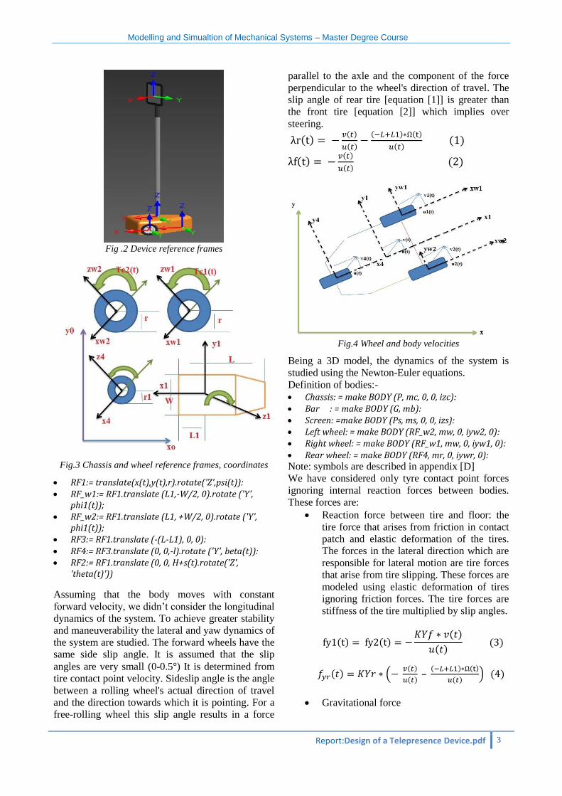
Fig .2 Device reference frames
Fig.3 Chassis and wheel reference frames, coordinates
RF1:= translate(x(t),y(t),r).rotate('Z',psi(t)): RF_w1:= RF1.translate (L1,-W/2, 0).rotate ('Y',
phi1(t)); RF_w2:= RF1.translate (L1, +W/2, 0).rotate ('Y',
phi1(t)); RF3:= RF1.translate (-(L-L1), 0, 0): RF4:= RF3.translate (0, 0,-l).rotate ('Y', beta(t)): RF2:= RF1.translate (0, 0, H+s(t).rotate('Z',
'theta(t)'))
Assuming that the body moves with constant
forward velocity, we didn’t consider the longitudinal
dynamics of the system. To achieve greater stability
and maneuverability the lateral and yaw dynamics of
the system are studied. The forward wheels have the
same side slip angle. It is assumed that the slip
angles are very small (0-0.5 ) It is determined from
tire contact point velocity. Sideslip angle is the angle
between a rolling wheel's actual direction of travel
and the direction towards which it is pointing. For a
free-rolling wheel this slip angle results in a force
parallel to the axle and the component of the force
perpendicular to the wheel's direction of travel. The
slip angle of rear tire [equation [1]] is greater than
the front tire [equation [2]] which implies over
steering.
( ) ( )
( ) ( ) ( )
( ) ( )
( ) ( )
( ) ( )
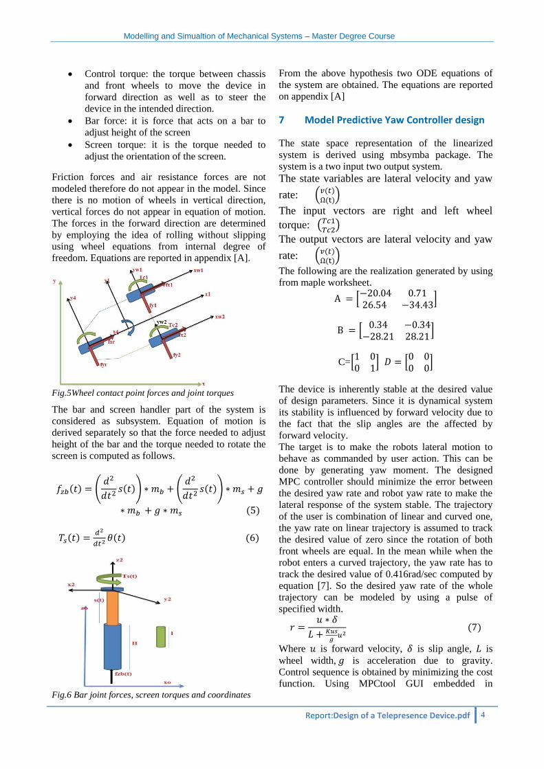
Fig.4 Wheel and body velocities
Being a 3D model, the dynamics of the system is
studied using the Newton-Euler equations.
Definition of bodies:-
Chassis: = make BODY (P, mc, 0, 0, izc): Bar : = make BODY (G, mb): Screen: =make BODY (Ps, ms, 0, 0, izs): Left wheel: = make BODY (RF_w2, mw, 0, iyw2, 0): Right wheel: = make BODY (RF_w1, mw, 0, iyw1, 0): Rear wheel: = make BODY (RF4, mr, 0, iywr, 0): Note: symbols are described in appendix [D]
We have considered only tyre contact point forces
ignoring internal reaction forces between bodies.
These forces are:
Reaction force between tire and floor: the
tire force that arises from friction in contact
patch and elastic deformation of the tires.
The forces in the lateral direction which are
responsible for lateral motion are tire forces
that arise from tire slipping. These forces are
modeled using elastic deformation of tires
ignoring friction forces. The tire forces are
stiffness of the tire multiplied by slip angles.
( ) ( ) ( )
( ) ( )
( ) ( ( )
( ) –
( ) ( )
( )) ( )
Gravitational force
Modelling and Simualtion of Mechanical Systems – Master Degree Course
Report:Design of a Telepresence Device.pdf 4
Control torque: the torque between chassis
and front wheels to move the device in
forward direction as well as to steer the
device in the intended direction.
Bar force: it is force that acts on a bar to
adjust height of the screen
Screen torque: it is the torque needed to
adjust the orientation of the screen.
Friction forces and air resistance forces are not
modeled therefore do not appear in the model. Since
there is no motion of wheels in vertical direction,
vertical forces do not appear in equation of motion.
The forces in the forward direction are determined
by employing the idea of rolling without slipping
using wheel equations from internal degree of
freedom. Equations are reported in appendix [A].
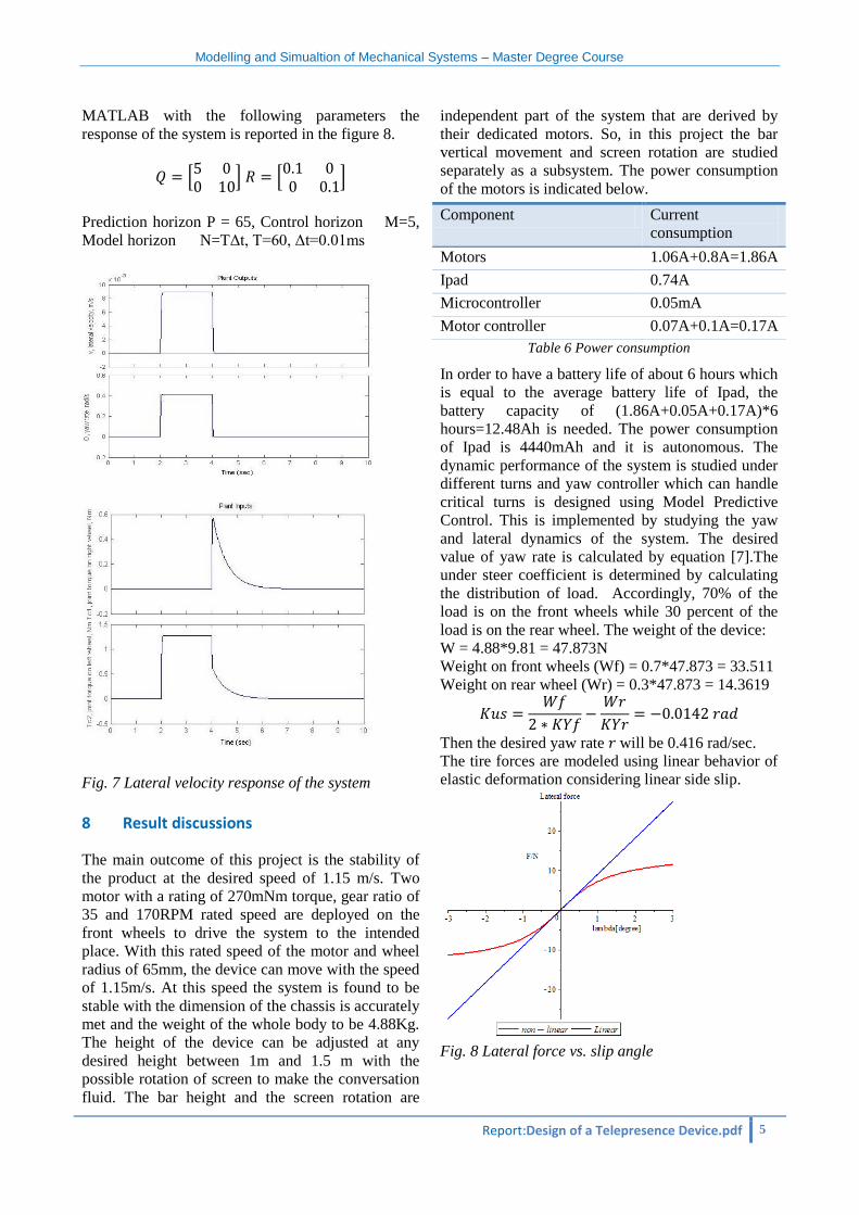
Fig.5Wheel contact point forces and joint torques
The bar and screen handler part of the system is
considered as subsystem. Equation of motion is
derived separately so that the force needed to adjust
height of the bar and the torque needed to rotate the
screen is computed as follows.
( ) (
( )) (
( ))
( )
( )
( ) ( )
Fig.6 Bar joint forces, screen torques and coordinates
From the above hypothesis two ODE equations of
the system are obtained. The equations are reported
on appendix [A]
7 Model Predictive Yaw Controller design
The state space representation of the linearized
system is derived using mbsymba package. The
system is a two input two output system.
The state variables are lateral velocity and yaw
rate: ( ( ) ( ))
The input vectors are right and left wheel
torque: ( )
The output vectors are lateral velocity and yaw
rate: ( ( ) ( ))
The following are the realization generated by using
from maple worksheet.
*
+
*
+
C=*
+ *
+
The device is inherently stable at the desired value
of design parameters. Since it is dynamical system
its stability is influenced by forward velocity due to
the fact that the slip angles are the affected by
forward velocity.
The target is to make the robots lateral motion to
behave as commanded by user action. This can be
done by generating yaw moment. The designed
MPC controller should minimize the error between
the desired yaw rate and robot yaw rate to make the
lateral response of the system stable. The trajectory
of the user is combination of linear and curved one,
the yaw rate on linear trajectory is assumed to track
the desired value of zero since the rotation of both
front wheels are equal. In the mean while when the
robot enters a curved trajectory, the yaw rate has to
track the desired value of 0.416rad/sec computed by
equation [7]. So the desired yaw rate of the whole
trajectory can be modeled by using a pulse of
specified width.
( )
Where is forward velocity, is slip angle, is
wheel width, is acceleration due to gravity.
Control sequence is obtained by minimizing the cost
function. Using MPCtool GUI embedded in
Modelling and Simualtion of Mechanical Systems – Master Degree Course
Report:Design of a Telepresence Device.pdf 5
MATLAB with the following parameters the
response of the system is reported in the figure 8.
*
+ *
+
Prediction horizon P = 65, Control horizon M=5,
Model horizon N=TΔt, T=60, Δt=0.01ms
Fig. 7 Lateral velocity response of the system
8 Result discussions
The main outcome of this project is the stability of
the product at the desired speed of 1.15 m/s. Two
motor with a rating of 270mNm torque, gear ratio of
35 and 170RPM rated speed are deployed on the
front wheels to drive the system to the intended
place. With this rated speed of the motor and wheel
radius of 65mm, the device can move with the speed
of 1.15m/s. At this speed the system is found to be
stable with the dimension of the chassis is accurately
met and the weight of the whole body to be 4.88Kg.
The height of the device can be adjusted at any
desired height between 1m and 1.5 m with the
possible rotation of screen to make the conversation
fluid. The bar height and the screen rotation are
independent part of the system that are derived by
their dedicated motors. So, in this project the bar
vertical movement and screen rotation are studied
separately as a subsystem. The power consumption
of the motors is indicated below.
Component Current
consumption
Motors 1.06A+0.8A=1.86A
Ipad 0.74A
Microcontroller 0.05mA
Motor controller 0.07A+0.1A=0.17A
Table 6 Power consumption
In order to have a battery life of about 6 hours which
is equal to the average battery life of Ipad, the
battery capacity of (1.86A+0.05A+0.17A)*6
hours=12.48Ah is needed. The power consumption
of Ipad is 4440mAh and it is autonomous. The
dynamic performance of the system is studied under
different turns and yaw controller which can handle
critical turns is designed using Model Predictive
Control. This is implemented by studying the yaw
and lateral dynamics of the system. The desired
value of yaw rate is calculated by equation [7].The
under steer coefficient is determined by calculating
the distribution of load. Accordingly, 70% of the
load is on the front wheels while 30 percent of the
load is on the rear wheel. The weight of the device:
W = 4.88*9.81 = 47.873N
Weight on front wheels (Wf) = 0.7*47.873 = 33.511
Weight on rear wheel (Wr) = 0.3*47.873 = 14.3619
Then the desired yaw rate will be 0.416 rad/sec.
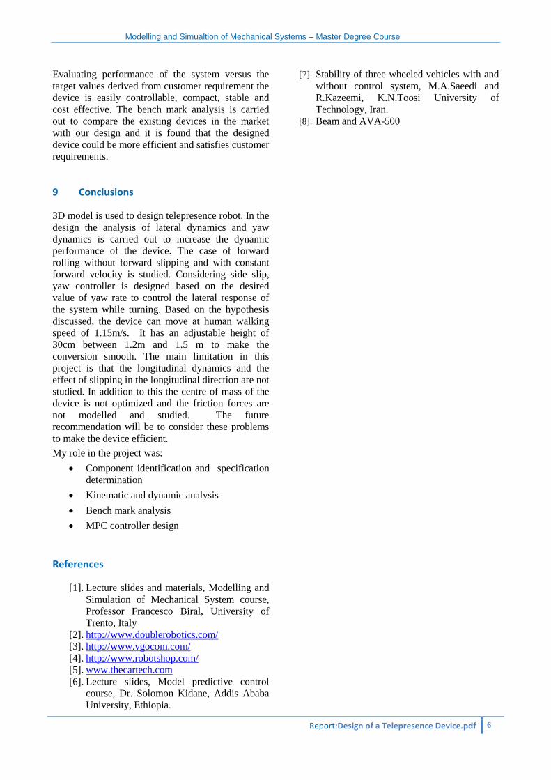
The tire forces are modeled using linear behavior of
elastic deformation considering linear side slip.
Fig. 8 Lateral force vs. slip angle
Modelling and Simualtion of Mechanical Systems – Master Degree Course
Report:Design of a Telepresence Device.pdf 6
Evaluating performance of the system versus the
target values derived from customer requirement the
device is easily controllable, compact, stable and
cost effective. The bench mark analysis is carried
out to compare the existing devices in the market
with our design and it is found that the designed
device could be more efficient and satisfies customer
requirements.
9 Conclusions
3D model is used to design telepresence robot. In the
design the analysis of lateral dynamics and yaw
dynamics is carried out to increase the dynamic
performance of the device. The case of forward
rolling without forward slipping and with constant
forward velocity is studied. Considering side slip,
yaw controller is designed based on the desired
value of yaw rate to control the lateral response of
the system while turning. Based on the hypothesis
discussed, the device can move at human walking
speed of 1.15m/s. It has an adjustable height of
30cm between 1.2m and 1.5 m to make the
conversion smooth. The main limitation in this
project is that the longitudinal dynamics and the
effect of slipping in the longitudinal direction are not
studied. In addition to this the centre of mass of the
device is not optimized and the friction forces are
not modelled and studied. The future
recommendation will be to consider these problems
to make the device efficient.
My role in the project was:
Component identification and specification
determination
Kinematic and dynamic analysis
Bench mark analysis
MPC controller design
References
[1]. Lecture slides and materials, Modelling and
Simulation of Mechanical System course,
Professor Francesco Biral, University of
Trento, Italy
[2]. http://www.doublerobotics.com/
[3]. http://www.vgocom.com/
[4]. http://www.robotshop.com/
[5]. www.thecartech.com
[6]. Lecture slides, Model predictive control
course, Dr. Solomon Kidane, Addis Ababa
University, Ethiopia.
[7]. Stability of three wheeled vehicles with and
without control system, M.A.Saeedi and
R.Kazeemi, K.N.Toosi University of
Technology, Iran.
[8]. Beam and AVA-500
Modelling and Simualtion of Mechanical Systems – Master Degree Course
Report:Design of a Telepresence Device.pdf 7
Appendix
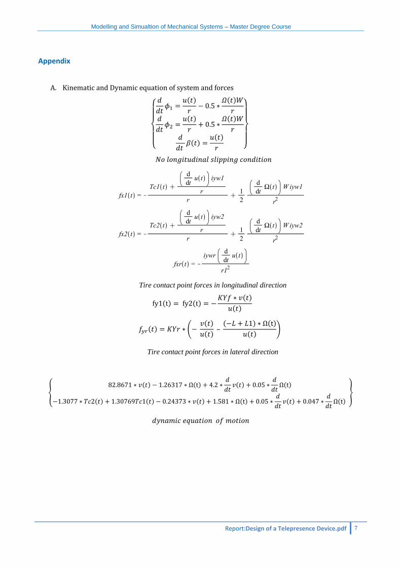
A. Kinematic and Dynamic equation of system and forces
{
( )
( )
( )
( )
( )
( )
}
Tire contact point forces in longitudinal direction
( ) ( ) ( )
( )
( ) ( ( )
( ) – ( ) ( )
( ))
Tire contact point forces in lateral direction
{ ( ) ( )
( )
( )
( ) ( ) ( ) ( )
( )
( )
}
Modelling and Simualtion of Mechanical Systems – Master Degree Course
Report:Design of a Telepresence Device.pdf 8
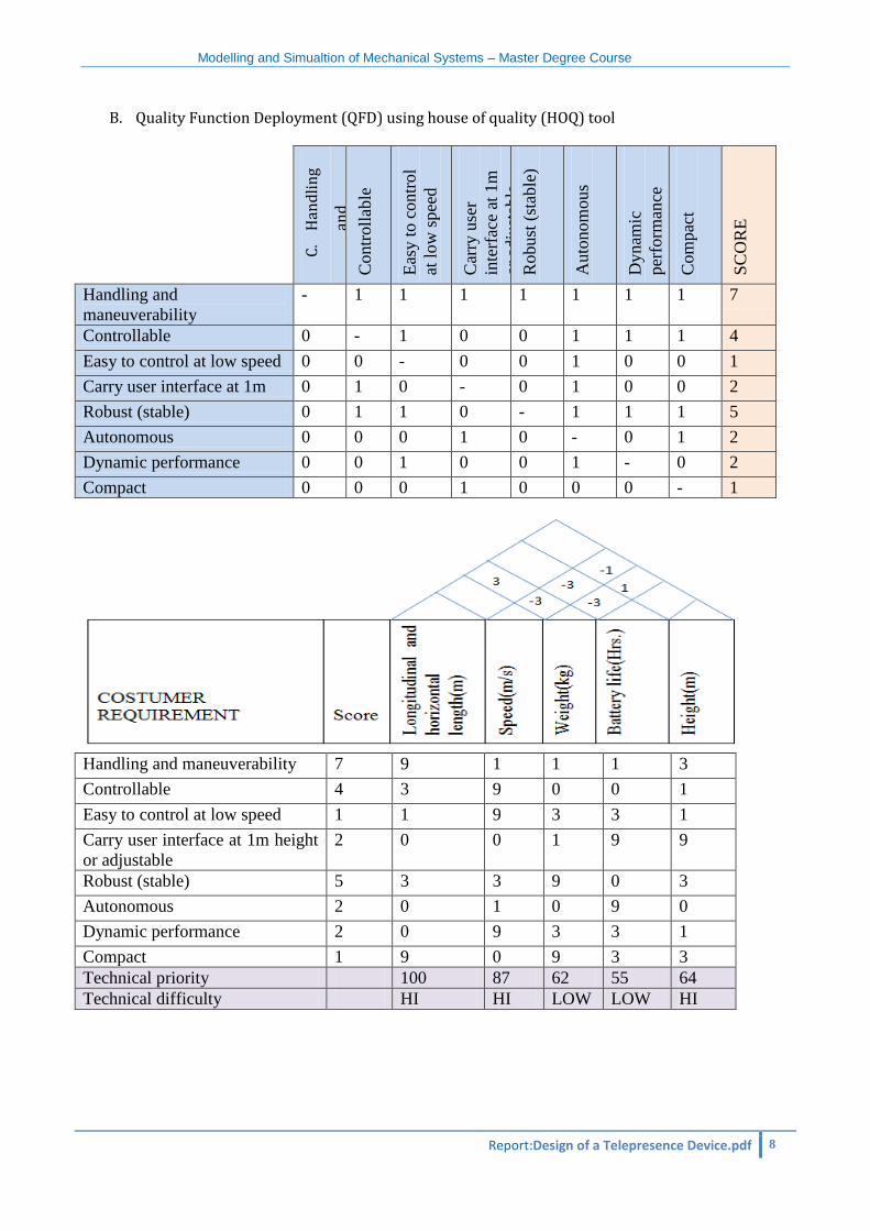
B. Quality Function Deployment (QFD) using house of quality (HOQ) tool
C.
Han
dli
ng
and
man
euve
r
abil
ity
Contr
oll
able
Eas
y t
o c
ontr
ol
at l
ow
spee
d
Car
ry u
ser
inte
rfac
e at
1m
or
adju
stab
le
Robust
(st
able
)
Auto
nom
ous
Dynam
ic
per
form
ance
Com
pac
t
SC
OR
E
Handling and
maneuverability
- 1 1 1 1 1 1 1 7
Controllable 0 - 1 0 0 1 1 1 4
Easy to control at low speed 0 0 - 0 0 1 0 0 1
Carry user interface at 1m 0 1 0 - 0 1 0 0 2
Robust (stable) 0 1 1 0 - 1 1 1 5
Autonomous 0 0 0 1 0 - 0 1 2
Dynamic performance 0 0 1 0 0 1 - 0 2
Compact 0 0 0 1 0 0 0 - 1
Handling and maneuverability 7 9 1 1 1 3
Controllable 4 3 9 0 0 1
Easy to control at low speed 1 1 9 3 3 1
Carry user interface at 1m height
or adjustable
2 0 0 1 9 9
Robust (stable) 5 3 3 9 0 3
Autonomous 2 0 1 0 9 0
Dynamic performance 2 0 9 3 3 1
Compact 1 9 0 9 3 3
Technical priority 100 87 62 55 64
Technical difficulty HI HI LOW LOW HI
Modelling and Simualtion of Mechanical Systems – Master Degree Course
Report:Design of a Telepresence Device.pdf 9
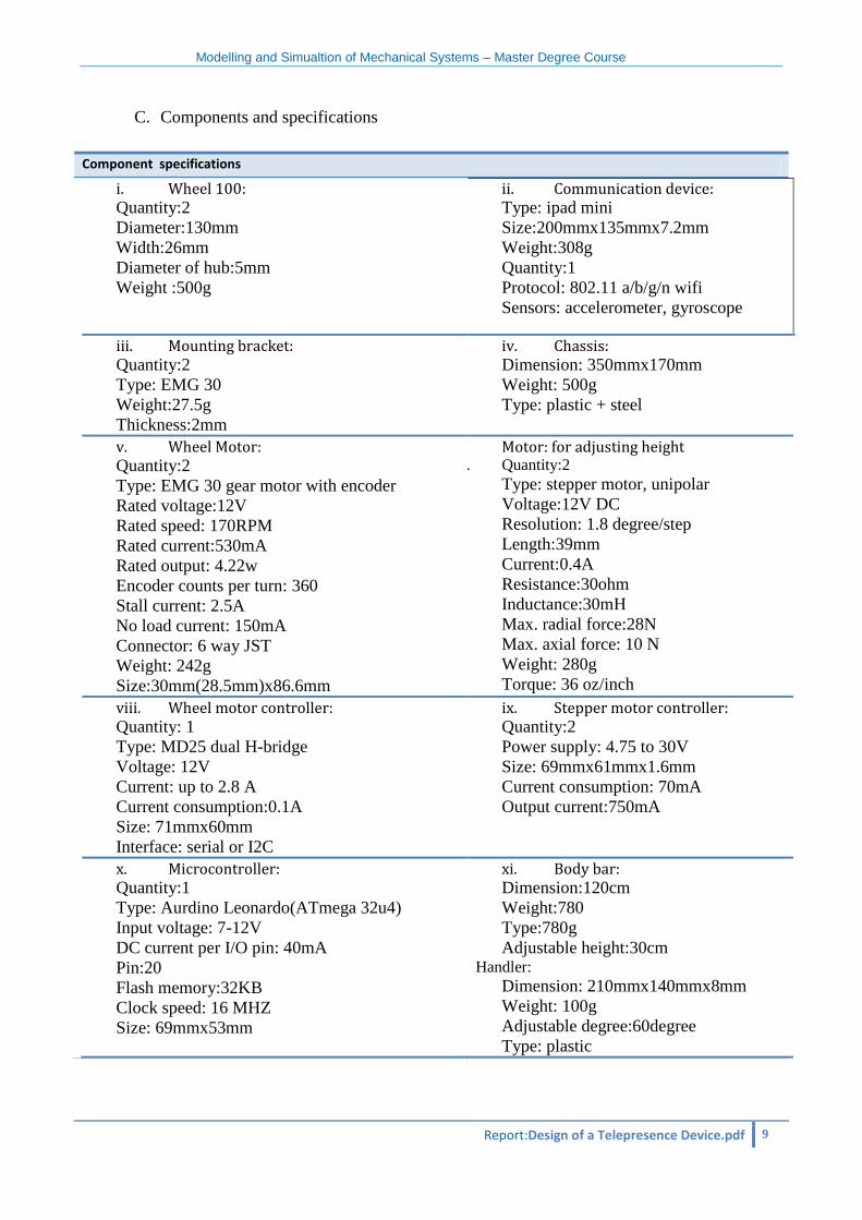
C. Components and specifications
Component specifications
i. Wheel 100: Quantity:2
Diameter:130mm
Width:26mm
Diameter of hub:5mm
Weight :500g
ii. Communication device: Type: ipad mini
Size:200mmx135mmx7.2mm
Weight:308g
Quantity:1
Protocol: 802.11 a/b/g/n wifi
Sensors: accelerometer, gyroscope
iii. Mounting bracket: Quantity:2
Type: EMG 30
Weight:27.5g
Thickness:2mm
iv. Chassis: Dimension: 350mmx170mm
Weight: 500g
Type: plastic + steel
v. Wheel Motor: Quantity:2
Type: EMG 30 gear motor with encoder
Rated voltage:12V
Rated speed: 170RPM
Rated current:530mA
Rated output: 4.22w
Encoder counts per turn: 360
Stall current: 2.5A
No load current: 150mA
Connector: 6 way JST
Weight: 242g
Size:30mm(28.5mm)x86.6mm
vi. Motor: for adjusting height vii. Quantity:2
Type: stepper motor, unipolar
Voltage:12V DC
Resolution: 1.8 degree/step
Length:39mm
Current:0.4A
Resistance:30ohm
Inductance:30mH
Max. radial force:28N
Max. axial force: 10 N
Weight: 280g
Torque: 36 oz/inch
viii. Wheel motor controller: Quantity: 1
Type: MD25 dual H-bridge
Voltage: 12V
Current: up to 2.8 A
Current consumption:0.1A
Size: 71mmx60mm
Interface: serial or I2C
ix. Stepper motor controller: Quantity:2
Power supply: 4.75 to 30V
Size: 69mmx61mmx1.6mm
Current consumption: 70mA
Output current:750mA
x. Microcontroller: Quantity:1
Type: Aurdino Leonardo(ATmega 32u4)
Input voltage: 7-12V
DC current per I/O pin: 40mA
Pin:20
Flash memory:32KB
Clock speed: 16 MHZ
Size: 69mmx53mm
xi. Body bar: Dimension:120cm
Weight:780
Type:780g
Adjustable height:30cm Handler:
Dimension: 210mmx140mmx8mm
Weight: 100g
Adjustable degree:60degree
Type: plastic
Modelling and Simualtion of Mechanical Systems – Master Degree Course
Report:Design of a Telepresence Device.pdf 10
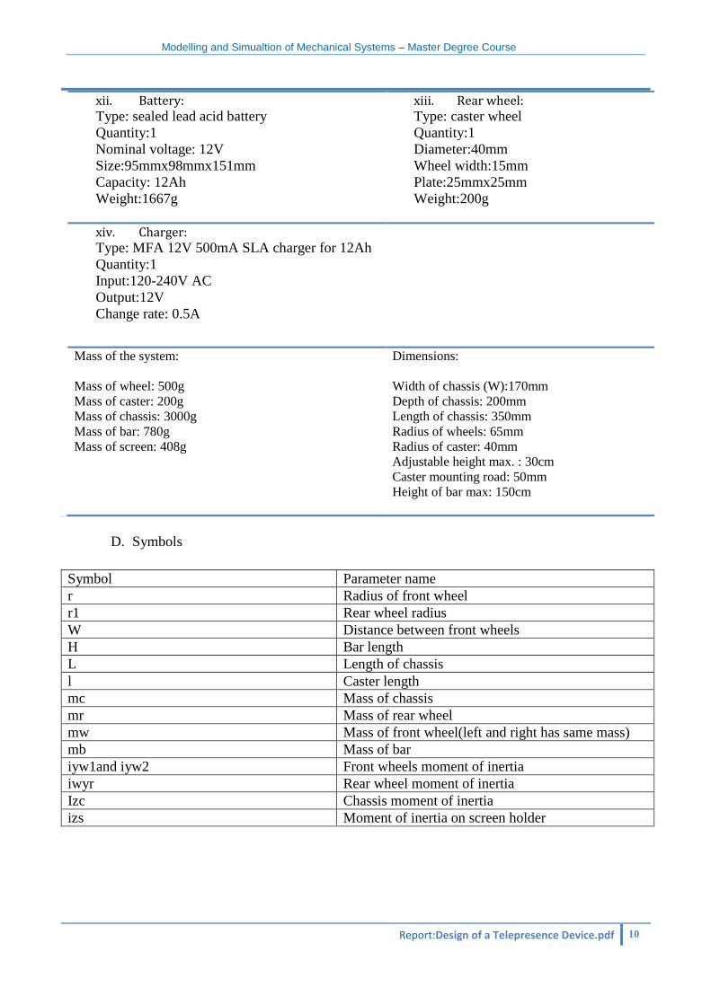
xii. Battery: Type: sealed lead acid battery
Quantity:1
Nominal voltage: 12V
Size:95mmx98mmx151mm
Capacity: 12Ah
Weight:1667g
xiii. Rear wheel: Type: caster wheel
Quantity:1
Diameter:40mm
Wheel width:15mm
Plate:25mmx25mm
Weight:200g
xiv. Charger: Type: MFA 12V 500mA SLA charger for 12Ah
Quantity:1
Input:120-240V AC
Output:12V
Change rate: 0.5A
Mass of the system:
Mass of wheel: 500g
Mass of caster: 200g
Mass of chassis: 3000g
Mass of bar: 780g
Mass of screen: 408g
Dimensions:
Width of chassis (W):170mm
Depth of chassis: 200mm
Length of chassis: 350mm
Radius of wheels: 65mm
Radius of caster: 40mm
Adjustable height max. : 30cm
Caster mounting road: 50mm
Height of bar max: 150cm
D. Symbols
Symbol Parameter name
r Radius of front wheel
r1 Rear wheel radius
W Distance between front wheels
H Bar length
L Length of chassis
l Caster length
mc Mass of chassis
mr Mass of rear wheel
mw Mass of front wheel(left and right has same mass)
mb Mass of bar
iyw1and iyw2 Front wheels moment of inertia
iwyr Rear wheel moment of inertia
Izc Chassis moment of inertia
izs Moment of inertia on screen holder


![[FRC 2014] Robot Simulation Tutorial](https://img.pdfslide.us/doc/110x75/55cf850f5503465d4a8b4fba/frc-2014-robot-simulation-tutorial.jpg)