Embed Size (px)
Citation preview

155
Design and Simulation of Electrocardiogram Circuit with Automatic Analysis of ECG Signal
Tosin Jemilehin, Michael Adu
An electrocardiogram (ECG) is the graphical record of bioelectric signal generated by the human body during cardiac cycle, it tells a lot about the medical status of an individual. A typical ECG waveform consist of the P, Q, R, S and T wave. The automatic ECG signal analysis comprises of using computational method/approach in extracting important features and classification of ECG waveform. This paper presents a concise ECG circuit design using an instrumentation amplifier and a band-pass passive filter. It also present the process involved in analysis of ECG signal. The first stage is the pre-filtering stage, followed by feature extraction of the signal. QRS complex is first extracted followed by P and T wave detection, also the FFT of the signal is also extracted. These features are fed into the classifier for proper classification. A pattern recognition neural network is used for classification, prior to the full deployment of the neural network, it is trained by pre-recorded ECG signal downloaded from the MIT/BIH Arrhythmias database. The neural network gave a satisfactory result with accuracy of around 87%.The whole ECG signal analysis is packaged into a MATLAB GUI for ease of use.
Keywords: Electrocardiogram, ECG circuit, feature extraction, neural network, heart rate detection
1. Introduction
An electrocardiogram (ECG) is a graphical record of bioelectrical signal generated by the human body during cardiac cycle which refers to the period
during which oxygen deficient blood enters the heart and gets oxygenated in the lungs and sent back to the body. ECG graphically gives useful information that
relates to the heart functioning, it also says a lot about the patient’s health status
ranging from stress level, heart rate, side effect after medication and so on. Cells in humans act like little batteries [1]. These cells have different ion concentrations
inside and outside of their membranes which create small electric potentials called
ANALELE UNIVERSIT ĂŢII
“EFTIMIE MURGU” RE ŞIŢA
ANUL XXIII, NR. 1, 2016, ISSN 1453 - 7397

156
bio-potentials. When there is a disturbance in a bio-potential this gives rise to an action potential which is the depolarization and repolarization of the cell ,by default
when a cell is at its rest, it is always in an electronegative state, but the disturbance causes it to reach a certain bio-potential threshold where positive ion
nodes on the cell membrane opens up and allows positive ions to flow into the cell,
this brings the cell in an electropositive state, this process is called depolarization, therefore repolarization occurs when the cell goes back to the electronegative
state. Essentially, the action potentials from different nodes in the heart are what make up electrocardiograph (ECG) signals. ECG signals are comprised of the
superposition of the different action potentials from different part of the heart. A typical ECG signal is fully described using PQRST waves, each wave gives
information as to the magnitude and nature of the electrical signal generated by
various part of the heart with the time at which it occurs. Figure 1 shows a typical ECG waveform and table 1 shows the timing between each sub-waves.
Figure 1. ECG signal showing waves and intervals
Table 1. Timing information of a typical ECG signal
Wave/Segment/Interval Duration(sec)
P wave 0.1 ±0.05
PR segment 0.1 ±0.05
PR interval 0.2 ±0.05
QRS complex 0.1 ±0.05
QT interval 0.4 ±0.05
T wave 0.12 ±0.05

157
An electrocardiogram machine act like a galvanometer whereby it’s positive and negative probe are placed at two adjacent point on the heart, when the heart
cells undergo depolarization and repolarization, the galvanometer deflects in response to the direction of the electrical vector produced by the heart per time.
The concept of galvanometer is realized efficiently using a difference amplifier
which also helps in amplifying the small ECG signal that can be read easily using a scope.
The automatic ECG signal analysis comprises of using computational method/approach in extracting important features and classification of ECG
waveform. It gets information about each component of an ECG signal and arrange it in such a way that will be understood by the classifier which classifies the beat.
2. Materials and methods
Instrumentation amplifier
One of the most useful and versatile op amp circuits for precision measure-
ment and process control is the instrumentation amplifier (IA) [2]. An IC package INA128 can be used is a low power, general purpose instrumentation amplifier of-
fering excellent accuracy. A single external resistor sets any gain from 1 to 10,000, it has a high common-mode rejection of about 120dB at gain greater than 100 [3]
The gain equation for the amplifier is;
(1)
For INA128,
Therefore, the external gain resistor value is given by,
(2)
For gain G = 501,
Analog filtering
In practice, ECG signal will not come out clean as shown in figure 1, it is al-
ways mixed with noise which distort the signal and makes it difficult to get useful
information. One of the major noise associated with raw electrocardiogram is the
baseline drift which is usually caused by respiration at frequencies between 0.15-
0.3Hz and electromyographic noise which between DC to 10000Hz [4]. Others

158
noises are power line interference, patient-electrode motion artifact, electrosurgical
noise and so on. Passive low-pass filter (fc = 100Hz) and high-pass filter (fc =
0.1Hz) can be cascaded to form a band-pass filter.
For low-pass filter, the equation is given as,
(3)
Given, C = 1uF and fc = 100Hz
R = 1591
For high-pass filter the equation is same as for low-pass filter,
Given, C=100uF and fc = 0.1Hz
R=15913
Figure 2. (0.1Hz-100Hz) Passive band-pass filter
Right-leg drive circuit
The right-leg drive circuit serves as a protective circuit against over-current to
the body, aids common mode rejection of the preamplifier by sending the electro-
cardiogram signal got from the body back to the body but in a negative amplified
manner. It consists of a buffer stage (to avoid loading the instrumentation ampli-
fier internal circuitry) and an inverting amplifier stage (for negative amplification of
the signal). At the output, the right-leg drive circuit is further connected to a high
resistance resistor whose main function is to further protect the human for over-
current from the mains and during transient. The schematic diagram of the right-
leg drive circuit is shown in figure 3.

159
Figure 3. Right leg drive circuit
MIT/BIH arrythmias database
Due to the difficulty in taking a real Electrocardiogram signal from a subject due to cost of building the device or design complexity, there are online resources
that provide a means to experiment on already recorded Electrocardiograms.
Physionet, one of the available online resource stores pre-recorded signals in different databases from different medical institutions, one of the popular ones
around is the MIT/BIT arrhythmia database, and it has been used extensively in so many research work to test algorithms used in analysis of Electrocardiogram (ECG)
signal. In this paper, ECG records from the database will be used for testing the
ECG analysis algorithm and in training the neural network.
Signal pre-processing
During signal acquisition, some noises are also added to the ECG signal and
also, the analog filters designed for the signal acquisition are not 100% efficient
hence, it is expedient the acquired signal is pre-processed. Digital filters can be
designed to filter off unwanted frequency component from the signal. The baseline
wandering is suppressed by using the ‘detrend()’ function on MATLAB while low-
pass filtering is realized using the 1D-Median filter ,the filter performs averaging
over certain number of samples in order to smoothen successive spikes.
QRS complex detection
The most important feature in an Electrocardiogram signal is the QRS wave
detection and it is the first wave to be detected before any further feature extrac-tion because it serves has a reference point for location of other waves in the sig-
nal as shown in the figure above. The QRS complex contain the highest frequency
component in a beat and also the R-peak is the highest point in a beat while the Q-point and S-point are the highest point when the wave is inverted. Various algo-
rithms were postulated by Pan and Tompkins [5].

160
The pseudocode for the algorithm used in this work is written below
Take x(n) as digitized ECG samples (0<n<N-1) threshold = 0.4*max(x(n)) for n=1:N threshold=0.4*max(x) if (x(n) > x(n-1) and x(n) > x(n+1)) if (x(n) >= threshold) space =Index(x(n)) – Index(R_peak(i-1)) if space>100 x(n)=R_peak(i) endif endif endif endfor
Q and S point are detected using time-domain windowing, similar algorithm is
applied but Q-point is gotten in region R_peak(i)-50ms and S-point is gotten at region R_peak (i)+50ms.Note that the digitized ECG samples must be inverted to
make Q and S-point the highest point in their respective time-domain window. Successful implementation of the algorithm above will give us row vector of R-
peak, Q-peak, S-peak and their index in the digitized ECG sample. Where,
index(Q(i)) = index(R(i)) – 50ms and,
index(S(i)) = index(R(i)) + 50ms From the QRS complex detection, the heart rate for a particular record can be
detected by taking the difference between successive R-peak location for the whole record and take the average to get a single R-R duration.
The heart rate calculation is given by;
(4)
From the QRS complex detection, QRS area can also be calculated for each
heartbeat, the QRS complex can be likened to a triangle, and where the base is
the difference between the Q-wave and S-wave, the height can be approximated to be the R-peak.
P AND T wave detection
In literature, P-wave and T-wave are the most difficult to detect, but we have the timing information with us, therefore using R-peak location as a reference

161
point, P-wave can be said to be located around R-peak (i) – 100ms to 150ms and T-wave can be located around R-peak (i) + 150ms to 200ms, the idea of peak
finding is also employed in the section of interest. For easier detection, Q-peak can be used as reference point for P-wave and S-peak as reference point for T-wave.
In doing so, QT interval, PR interval and even few samples form the P wave and T
wave can be extracted also to aid classification.
Statistical/frequency domain feature
The statistical or frequency domain feature of an ECG record or beat contains
information needed to know the magnitude of the contribution of each frequency to the formation of that particular signal or everything about the frequency compo-
sition of the signal. The frequency domain feature includes
• Autocorrelation of the signal
• Power spectral density of the signal
• Fast Fourier Transform (FFT) of the signal
All the frequency domain feature can be gotten using special function in Signal Processing toolbox of MATLAB.
Feature extracted vector
In total, there are 8 features extracted from each heartbeat, the features can be later increased depending on the performance of the classifier, these features
will also serve as input for the classifier, they are listed in Table 2.
Table 2. Features extracted
Feature Description
1 QRS duration
2 QRS Area
3 PR interval
4 P peak
5 RT interval
6 QT interval
7 T peak
8 Signal Energy(PSD)
Artificial neural network
Classification of Electrocardiogram signal is done using the neural network, it takes as an input, the extracted features and output the desired result. A neural
network is a massively parallel-distributed processor that has a natural propensity
of storing experiential knowledge and making it available for use [6]. It resembles the brain in that it acquires knowledge through learning process and the knowl-
edge are stored using weights/biases between interconnected nodes or neurons.

162
In this paper, the pattern recognition neural network will be used in classification of the electrocardiogram signal.
Figure 4. Neural network architecture showing the input neurons, hidden layer and output neurons
The pattern recognition neural network should be able to classify an ECG beat
into one of these three. • Normal beat(N)
• Left Bundle Branch Block (LBBB)
• Right Bundle Branch Block(RBBB)
The most common ECG waveforms that fall under the above listed categories were selected from the MIT/BIH database. To achieve clustering similar waveforms
into the four different classes, the neuron output layer should be three (3).The
target vector was arranged as the desired output for each class using a set of Boolean values for easy adjustability of the system. Accompanying each record in
the database is an annotation file in which each beat in the record have been classified by expert cardiologist, the annotator was used in assembling the training
dataset into groups by grouping beats into different classes. The output vectors
are shown the table 3;
Table 3. Heart rhythm and corresponding output vector
Signal Output vector Heart Condition
N [ 1 0 0 ] Normal
R [0 0 1] Right Bundle Branch Block
L [1 0 1] Left Bundle Branch Block
The neural network structure used is shown in figure 5 below, from the diagram it can be seen that the neural has two neurons in the hidden layer with

163
the tan-sigmoid transfer function. The output neurons have the linear transfer function and the final output gives a three values output whereby each value can
be a zero or one.
Figure 5. Pattern recognition neural network view
After network configuration, the network is trained with the available dataset from each heart rhythm downloaded from the database. The training algorithm
used is the scaled conjugate gradient method (trains cg) which is the best training
algorithm for pattern recognition. The training window is shown in figure 6 and the performance graph.
3. Result and discussion
Signal acquisition simulation result
The schematic diagram for the whole Electrocardiogram circuit is shown in figure 7. Each component of the full circuit is placed in a sub-circuit block. It can
be seen clearly from Figure 7, the POWER_SUPPLY block provide the necessary
bias voltage for the operational amplifiers. A LABVIEW virtual instrument (XLV1) generates the raw ECG signal, port RLeg is connected to the output of the Right-
Leg Drive circuit as described earlier. RArm and LArm are connected to the instrumentation amplifier and then further filtered by the filtering block (HPF and LPF). It should be noted that the connections are done via virtual part number so as to make the circuit tidy and for clarification purpose. The processed ECG signal
is displayed using the built-in oscilloscope in MULTISIM.
Figure 8 shows the processed ECG waveform via the oscilloscope. The oscilloscope is tuned to 200ms/div in the time axis and 500µv/div in the voltage
axis, thus the timing information of the ECG signal can be read easily. The P-wave is seen to occupy about half of a division hence we can say it has a duration of
about 100ms likewise the PR-segment occupies the other half of the division which
makes the PR-segment’s duration 100ms and PR-interval’s duration 200ms. The T-wave occupies about two-third of a division hence the duration is about 125ms.
The QRS-complex can be seen to occupy about half of a division which makes the duration about 100ms. Comparing the simulated ECG waveform timing calculated
to the standard timing given in Table 1, the timings look similar hence, they fall in
the same range which makes the simulation valid.

164
Figure 6. Neural network training and confusion matrix

165
Figure 7. Full ECG circuit and simulation result
ECG signal analysis simulation Digitized ECG signal from the MIT/BIH Arrhythmia database is fed into the
signal processing algorithm and the classifier for the simulation of this part of the project. Result for each signal processing stage is shown and discussed in this sec-
tion.
• Signal filtering
The digitized ECG signal gotten from the Arrhythmia database is noisy hence,
it needs filtering. The digital filter used is the median filter implemented using the midfilt1() function in MATLAB. Figure 9 shows the noisy signal and the filtered sig-
nal.
The median filter is used to implement a 4 sample moving average filter and it is also passed through the filter multiple times to improve or enhance the spectral
of the filter. As shown in figure 9 above, high frequency component in the noisy signal are smoothened out hence, the performance of the filter is satisfactory.
• Feature extraction
Filtering of the ECG signal makes it possible to perform further processing op-eration on the signal. QRS detection, P and T wave detection and statistical feature
extraction of the signal are discussed in this section.

166
Figure 8. Simulated ECG waveform using MULTISIM
Figure 9. Signal filtering stage
• QRS detection
Feeding-in the filtered ECG signal into the QRS detection algorithm. The
outcome of implementing this algorithm is shown in Figure 10. The green boxes indicate Q-wave peaks, red boxes indicate R-wave peaks and the blue boxes
represent S-wave peaks. The algorithm is seen to be efficient as it detects all the R peaks in the ECG record shown in Figure 10, though in noisy or bad heart rhythm,
there some misdetection but it is not significant as compared to the rightly
detected R peaks.
• P AND T WAVE DETECTION
Next phase of the feature extraction is the P and T wave extraction. The algo-rithm performs a time-domain windowing on the signal to detect the P and T wave
effectively. Figure 10 shows the ECG signal with P and T wave detected, the P-
wave peak is marked with red box while that of T-wave is marked with blue box.

167
The P wave detected are in their correct position with respect to other waves like-wise the T wave, which makes the algorithm very effective.
Figure 10. QRS complex detection result
Figure 11. P wave and T wave detection

168
• Frequency domain feature
The next phase of the feature extraction is the extraction of the statistical fea-ture of the ECG signal. Figure 12 shows the autocorrelation of the signal and the
Fast Fourier Transform (FFT) of the signal. The magnitude spectrum shows that most of the signal energies fall in the region 0Hz - 50Hz.
Figure 12. FFT and Signal energy
The signal extraction process helps in describing the timing information of the ECG signal. Shown in Figure 13 is the final report on the timing information of an
ECG signal on the MATLAB command window, it shows the R-R interval, heart rate and the QRS duration. The R-R, Heart rate and QRS duration are calculated by
averaging theirs for lets says 10 beats to get a single for each parameter. In addition, the timings are gotten using the sampling frequency- sample relationship.
To convert from a particular second ‘t’ to number of sample ‘n’
(5)
Figure 13. Feature extraction result on MATLAB command window

169
• Signal classification
The performance plot of the neural network training shows that the neural network performance satisfactory, the confusion matrix shows that the neural net-
work is around 87% accurate and below is the receiver operating characteristic (ROC), which is the graph of True positive rate (sensitivity) versus false positive
rate (1-specificity).The ROC plot for the training, validation and testing gives High
TP rate value in the overall plot and a low value in the (1-specificity) plot. Using the inbuilt statistical and probability package in MATLAB, the mean value for TP is
above 85% and the mean value for (1-specificity) below 0.9, that is the specificity is estimated to be above 90%. This is a satisfactory performance and can be im-
proved upon by increasing the amount of training dataset and also using a more suitable neural network model.
Figure 14. Receiver operating characteristic of the Neural network (ROC)
Furthermore, the ECG signal is classified into one of the Arrhythmia to be tested. The vector generated from feature extraction is fed into the input of the
neural network. The network is tested with a normal sinus rhythm, the output is also shown below. It can be seen the ECG signal is well classified and it follows the
output vector in table 3.
170
Figure 15. Signal classification result in MATLAB command window
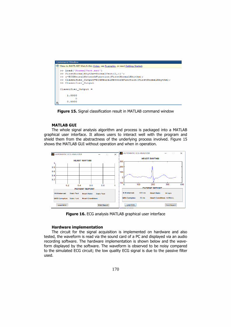
MATLAB GUI The whole signal analysis algorithm and process is packaged into a MATLAB
graphical user interface. It allows users to interact well with the program and shield them from the abstractness of the underlying process involved. Figure 15
shows the MATLAB GUI without operation and when in operation.
Figure 16. ECG analysis MATLAB graphical user interface
Hardware implementation
The circuit for the signal acquisition is implemented on hardware and also tested, the waveform is read via the sound card of a PC and displayed via an audio
recording software. The hardware implementation is shown below and the wave-
form displayed by the software. The waveform is observed to be noisy compared to the simulated ECG circuit; the low quality ECG signal is due to the passive filter
used.

171
Figure 17. Hardware implementation of the ECG circuit
4. Conclusion
This paper present electrocardiogram circuit design simulation. Analysis of ECG signal was implemented using MATLAB signal processing capability and neural
networks. Digital filters were designed for signal pre-processing, feature extraction algorithms were developed to determine P, Q, R, S and T wave timing, and also
the neural network was designed and trained using ECG signal acquired from the
MIT/BIH Arrhythmia database. The electrocardiogram circuit was tested in real life and it gave a satisfactory result, though the simulated circuit produced a cleaner
ECG signal compared to the real-life implementation, this is due to passive filters used and non-uniformity in manufacture of electronic components. The analysis of
ECG signal was simulated on MATLAB to classify a particular ECG signal acquired from the MIT/BIH Arrhythmia database. The acquired ECG signal was classified
correctly despite the fact that the classification accuracy of the neural network
designed was seen to be 87%.

172
References
[1] Kesto N.M., Electrocardiography Circuit Design, ECE 480 - DESIGN TEAM 3, 2013.
[2] Sadiku M., Alexander C., Fundamental of Electric Circuits, New-York:
McGraw Hills. [3] Texas Instruments, INA128, Texas: Texas Instruments Inc, 2005.
[4] Andrew T.R., Gari D.C., Roger G.M., The Physiological Basis of the Electrocardiogram, Advanced Methods and Tools for ECG Data Analysis,
Norwood, Artech House Inc, 2006, pp. 1-24.
[5] Pan J., Tompkins W.J., A real-time qrs detection algorithm, Biomedical Engineering, vol. 3, pp. 230-236, 1985.
[6] Howard D., Mark B., Martin H., Neural Network toolbox users' guide, Natick: The MathWorks inc, 2010.
Addresses:
• Jemilehin Tosin, “Department of Electrical and Electronics Engineering”,
Federal University of Technology, Akure, [email protected] • Engr Michael Adu, “Department of Electrical and Electronics Engineering”,
Federal University of Technology, Akure, [email protected]