Embed Size (px)
Citation preview

DESIGN AND SIMULATION OF DIE AND PUNCH FOR SHEET METAL ON
ROUND BENDING
TEH SOON CHIANG
A report submitted in fulfilment of the
requirements for the award of the degree of
Bachelor of Mechanical Engineering
I-. t I - .4-
Faculty of Mechanical Engineering
Universiti Malaysia P
- •••) 4 •_• ' ' -.
' . ._._,_•, ,
NOVEMBER 2007

ABSTRACT
The deflection between FEA simulation and experiment test results still exist
which affects the quality and accuracy of the results. Addressing it has become more
challenging due to more stringent demands on simulation processes. It is becoming
necessary to very rapidly identify sources of unnatural deflection for diagnostic and
intervention purposes. The problem include the less efficient design for die and
punch, limited die and punch for complex shape, and the unknown displacement
control for round shape bending process of sheet metal. For methodology, a v-shape
bend experiment and a v-shape bend simulation is done to show result. Comparison
between the results of experiment and simulation to measure Algor's analysis
accuracy which is applied to simulate round shape bend of sheet metal.
Characteristics of sheet metal such as springback are observed during the simulation
analysis. in addition, several designs are proposed for round shape bend and to
determine which design is best for bending 62.5 mm radius sheet metal. A data sheet
containing the displacement control of the press brake machine is developed from
the simulation. The framework used to develop the data sheet is general enough for
further investigation by either evaluating other designs of its components or by
extending its application to other problems.
V

:3119 IM ri
Perbezaan nilai wujud diantara keputusan sirnulasi FEA dengan keputusan
eksperimen dan mi telali mempengaruhi qualiti dan kejituan keputusan akhir.
Penerapan teknik tersebut amat :mencabar disëbabkan oleh permintaan yang
menyuiitkan. Teknik mi juga perlu untuk rnengesahkan punca perbezaan untuk
diagnostik. Masalah projek termasuk kecacatan reka bentuk acuan dan penekan,
kekurangan acuan dan penekan untuk reka bentuk rumit, dan nilai-nilai untuk
sesaran penumbuk dálam proses rnembenthk keping besi bentuk bulat. Dalam proses
perkaedahan, keputusan eksperimen dengan simulasi :membengkok keping besi
bentuk 'V' telah dibandingkan untuk.rnengesahkan kejituan kaedah simulasi tersebut.
Kemudian, kaedah simulasi mi digunakan untuk analisa prosess pembentukan
keping besi bentuk bulat. Ciri-ciri keping besi seperti 'springback' dilihat semasa
simulasi. Selain itu, beberapa .reka hentuk teiah dibandingkan untuk mendapatkan
reka bentuk acuan dengan penekan yang sesuai untuk membengkok keping besi
pada 62.5 mm jejari. Satu jadual data sesaran untuk mesin telah dihasilkan daripada
simulasi keping besi bentuk bulat. Rangka untuk :menhasiikan jadual tersebut
adalah memadai untuk ;rnelanjut penyeiidikan dengan menilai rekabentuk lain atau
digunakan untuk masalah lain..
A

TABLE OF CONTENTS
CHAPTER
TITLE
PAGE
TITLE
1
STUDENT DECLARATION
Ii
DEDICATION
111
ACKNOWLEDGEMENT
iv
ABSTRACT
V
ABSTRAK
vi
TABLE OF CONTENTS
vii
LIST OF TABLE
x
LIST OF FIGURE
xi
LIST OF SYMBOL
xlii
LIST OF APPENDICES
xiv
INTRODUCTION 1
1.1 Project Background 1
1.2 Problem Statement 2
1.3 Project Objective 2
1.4 Project Scopes 3
2 LITERATURE REVIEW 4
2.1 introduction 4
vii

2.2 Sheet Metal Processes 5
2.2.1 Shearing 5
2.3 Sheet Metal Characteristics 6
2.4 Sheet Metal Bending 7
2.4. 1 Added Bending Operation 8
2.5 Press Brake Machine 9
2.6 Materials Selection and Materials in Design 9
2.6.1 High Speed Steels 10
2.7 Engineering Design 10
2.7.1 Conceptual Design 11
2.7.2 Designing for Manufacturability 12
2.8 Finite Element Analysis 13
2.8.1 Algor's Simulation 13
3 METHODOLOGY IS
3.1 Introduction 15
3.2 The Overall Methodology 15
3.2.1 Conceptual Design 17
3.2.2 Mechanical Design & Drawing 17
3.3 Experimental Procedure for V-shape Bending 19
3.4 FEA Software (ALGOR) 19
3.4.1 Material Properties 20
3.4.2 Model Building 20
34.3 Aigor Simulation Analysis 21
3.5 Data Collection 23
3.6 Documentation 24
4 RESULT AND DISCUSSION 25
4.1 Introduction 25
vii'

4.2 Result of V-Shape Bend Experiment and
ALGOR Simulation 25
4.3 Result of Round Bend Simulation Analysis 31
5 CONCLUSION 41
5.1 Conclusion 41
5.2 Recommendations 42
REFERENCES 43
APPENDICES 45 69
ix

LIST OF TABLES
TABLE NO. TITLE PAGE
4.1 Bend angle oIgaivanized iron sheet metal 26
4.2 Bend angle of mild steel sheet metal 26
4.3 Bend angle of aluminum sheet metal 26
4.4 Reference data sheet for bending 62.5mm radius
sheet metal 38
x

LIST OF FIGURES
FIGURE NO. TITLE PAGE
2.1 Bending terminology 7
3.1 Flowchart of overall methodology 16
3.2 3-D model of the base for round shape and v-shape
sheet metal bending 18
3.3 :3-D model of the punch for round shape sheet
metal bending 18
3.4 Illustration of constrains and displacements modes
on the V-shape bend model 21
3.5 illustrations of constrains and displacements modes
on the round shape bend model 21
4.1 Displacement and angle of galvanized iron sheet metal 26
4.2 Displacement and angle of mild steel sheet metal 26
4.3 Displacement Sand angle of aluminum sheet metal 27
4.4 Von Mises Stress of v-shape bend Simulation 27
4.5 Tooling dimension for V-shape bending 28
4.6 Tooling dimension for round shape bending 31
4.7 Displacement magnitude of 125 diameter punch 31
4.8 Displacement magnitude of 120 diameter punch 32
4.9 Displacement magnitude of 115 diameter punch 32
4.10 Displacement with springback for 125mm diameter
punch 34
4.11 Displacement with ;springback for 120mm diameter
punch 35
xi

xli
4.12 Displacement with :springback for ii 5mm diameter
punch 35
4.13 Displacement magnitude vs sheet metal radius for
punch with three different radiuses 37

LIST OF SYMBOLS
Lb Bend allowance
a - Bend angle
R - Bend radius
k - Constant
T - Sheet metal thickness
e - Minimum bend radius
xlii

LIST OF APPENDICES
APPENDIX TITLE PAGE
A Data analysis for V-shape bending from Algor 45
B Data analysis for Round-shape bending from
Algor 55
C Drawing of V-shape bend tool and die 65
D Drawing of Round-shape bend tool :and die 66
E Figure of machines in V-shape bend
Experiment 68
xiv
CHAPTER 1
INTRODUCTION
1.1 Project Background
The project is expected to design :and analysis the die and punch for sheet
metal on v-shape and round shape bending. The •sheet metal bending is a major
process in many sectors of industry. Throughout the years, technological advances
have allowed the production of extremely complex parts. However, the evolution
of die design and ultimate tryout has been a slow, cautious process based on the
trial-and-error and the experiences of skilled workers.
Because of its low cost and generally good strength and formability
characteristics, low carbon steel is the most commonly used sheet metal.
Incremental in-plane bending is a new and flexible 'manufacturing technology for
short production runs in a variety of sizes and ..shapes. The strip of sheet is bent
incrementally by an inclined punch beating according to the control program.
The incremental bending machine uses the numerical control technology.
The cross-sectional ratio of width to thickness of the sheet metal 'and the pitch are
important for in-plane bending conditions. The bending experiment is carried out
and some experimental results such as beating force, bending radius and strain
distribution are experimentally examined. The forming properties of in-plane
bending are clarified in this study.

2
The sheet metals are usually bent by a punch and die as base. There are
various manufacturing methods, either singly or in combination, are used in making
dies. These processes include casting, forging, machining, grinding, and electrical
and electrochemical methods of die sinking. Dies are usually heat treated for greater
hardness and wear resistance. When necessary, their surface profile and finish are
improved by grinding and polishing either by hand or by programmable industrial
robots.
1.2 Problem Statement
The problems of the current project are:
i. The design for die and punch are less efficient.
ii. Limited die ;and punch for complex shape.
iii. The displacement control for bending process of sheet metal are
unknown.
1.3 Project Objective
i. Experiment and analysis of v-bend characteristics using the
Trumabend V85S.
ii. Design and simulate of and punch for sheet metal on round
bending.
iii. Develop of round shape bend Data Sheet Reference for sheet metal.

3
1.4 Project Scopes
For the main purpose of this research, the following scopes are created:
i. Collecting the data from various sources for reference and analysis
for literature. The data collecting process is done manually or
automated depending on the situation.
ii. Develop the most efficient and simple design of the punch and die so
that they are easy to manufacture, complex shape and sizes are not
recommended.
iii. The next scope is geometry measurement which involves the
dimensions of a design including the length, width, thickness, height,
angle between lines, diameter etc. The dimensions of the design of
the die and punch are measured to form a .3-D view to get clearer
picture.
iv. Perform analysis by F.E.A and validation. Validation is the process
of checking if something satisfies a certain criterion. Validation is
important because it disallows data that can not possibly be either
true or real to be entered into a database or computer system.
V. Develop the methodology of the proposed design.

CHAPTER 2
LITERATURE REVIEW
2.1 Introduction
A critical literature review within a specific field or interest of research is
one of the most essential activities in the process of research. In order to produce a
more productive literature review, it is recommendable to include whole process of
selecting resources, reading and writing about previous research studies chosen
which includes the discussion about the drawing methods or techniques which are
applied to the modal to achieve maximum efficiency :and save time. In addition, this
section also includes argument of the designs of die to find out which design
provides the best performance. Besides that, the manufacturing process and
parameters are also discussed. Vital information is .transferred from external source
into this section such as the irtemet, reference book, and scientific journals edited
by well known professors around the world. Hence, this section acts as a platform
for the whole research to support and define each action performed during analysis
and experiment.

2.2 Sheet Metal Processes
Sheet metal parts are light weight and can have versatile shape due to its low
cost and generally good strength and formability characteristics. Thus, low-carbon
steel is the most commonly used sheet metal (Bruce et al., 2004).
Many Sheet Metal Forming processes are used to produce parts and shapes
and there is usually more than one method of manufacturing a sheet metal from a
given material. The broad categories of processing methods for materials are as
followed:
a). Roil forming: Long parts with constant complex cross-section.
b). Stretch forming: Large parts with shallow contours that is suitable for
low quantity production.
c). Drawing: Shallow or deep parts with relatively simple shapes for
high production rates.
d). Stamping: includes punching, Flanking, embossing, bending,
flanging, and coining.
e). Spinning: Small or large axisymmetric parts with good surface finish
and low tooling cost (Kalpakjian and Schmid., 2001).
2.2.1 Shearing
Sheet metal is usually removed from a large sheet or coil by shearing. The
sheet is cut by shear cutting tools, typically ones created by a punch and a die.
Several cutting operations are based on the shearing process include punching and

blanking. Punching is identified when the sheared slug is discarded while in
blanking usually theslug is -the partandthe rest is thrown (Bawa, 2004).
Die cutting is one of the most common operations used in the industry. Die
cutting is a shearing process that consist of the following:
i) Perforating - punching a number of holes in a sheet.
ii) Parting •- shearing the sheet into two or more pieces.
iii) Notching - removing pieces from edges.
iv) Lancing - leaving a tab without removing any material (Kalpakjian
and Schmid., 2001).
2.3 Sheet Metal Characteristics
Basically, the sheet metal forming uses various dies and tools to stretch and
bend the sheet. However, certain characteristics of ;:sheet metals must be checked
before considering the processes. Among the important effects of the characteristic
are as followed:
i) Grain size is to determine the surface roughness of the stretched sheet.
ii) Springback can cause distortion of part and affect the dimensional
accuracy of the sheet.
iii) Elongation is to determine the capability of the sheet metal to stretch
without failure and necking
iv) Yield point elongation also called Lueder's band or sti.etcher strains
which causes flamelike depression on the sheet surface (Crowson, R
et al., 2006).

7
2.4 Sheet Metal Bending
Sheet metal bending imparts stiffness to the part by increasing its moment of
inertia. For example, the flanges, beads, and seams increase the stiffness of structure
without adding any weight. The terminology used in bending of sheet or plate is
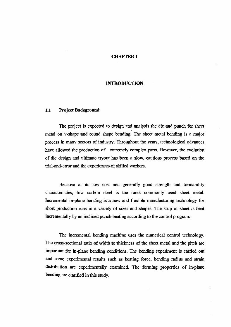
shown in Figure 2.1. (Giudice et al., 2006).
Bend allowance, L' length of bend,
/ IL a ngle,a
'11%
"^^T
Bend radius; R
Figure 2.1 Bending terminology
From the figure above, the bend allowance, Lb is the length of the neutral
axis in the bend. The position of Lb depends on the radius and the bend angle
according to the formula below:
Lba(R+kT) (1)
where 'a' is bend angle, T is sheet thickness, R is bend radius, and k is a constant.
Besides that, bending also considers the minimum bend radius. The
minimum bend radius refers to the radius at which the first crack appears at the outer
fibers of a sheet being bend. The minimum bend radius is given by the expression
e= l/((2RIT)+1) (2)
When the ratio of bend radius to thickness decreases causing tensile strain at the
fiber to increase and develop cracks (Parmley, 1997).

8
In addition, sheet metal bending also depends on the springback effect. All
material have modulus of elasticity, when recovery of :a bent sheet metal occurs is
known as springback. One of the methods of overcoming springback is by
overbending the part (Speck, 1997).
The Press-brake bending machine utilizes long dies and hydraulic press and
suitable for small production. The tooling is simple yet effective; their movement is
limited to up and down. However,, they are easily adaptable to a wi& range of
shapes. Moreover, the process can switch to automated to reduce cost and for high
production runs (Childs, 2004).
2.4.1 Added Bending Operation
There are a variety of processes of sheet 'metal bending. Among them are as
described below;
i) One of the most common is roll bending where the plates are bent
using a set of rolls. By modifying the distance between the rolls to
create various curvatures.
ii) 4-Slide Bending Machines are used for short pieces. These machines
comes with a variety of designs.
iii) The next operation is known as beading where the periphery of sheet
is bent into the jcavityof the die.
iv) The roll forming process is used 'for iforming continuous lengths of
sheet and suitable for high production runs (Schey, 2000).

2.5 Press Brake Machine
Sheet metals that are 2 meters in width or smaller and other narrow pieces
are usually bent in a press brake. This machine have long die and punch holders in a
mechanical or hydraulic press and is 'also suitable for low production runs. Besides
that, the dies and punches are inserted son the holders depending on the size of the
sheet metal to be bent (Walsh, 1999).
The press brake 'machine requires simple tooling and it is adaptable to a 'wide
variety of shapes. in addition to 'that, the press brake can be automated with the
computerized control system. The materials of the dies and punches range from
hardwood to carbides depending on the sheet. For most applications, carbon steel are
generally used (www.giobalspec. corn! LearnMore/ Manufacturing Process_
Equipment /Machine _Tools/Milling Machines).
2.6 Materials Selection and Materials in Design
The selection of the suitable material for a design is a crucial step in
manufacturing. The recognition of the importance of materials selection in design
can be seen in the present day product design which supports the' fact that materials
and manufacturing are closely linked in determining the product performance
(Charles etal., 1999).
A wrong selection of material can lead to failure of part and also to
unnecessary life-cycle cost. However, selecting the best material for a part involves
more than just selecting the suitable 'material with the properties to provide 'the
wanted performance. Besides that, it is also connected with the processing methods
Of transforming the material to the final part. In addition, the wrong material will

10
increase manufacturing cost and increase the cost of the part. The solution is to
perform simplification and systemization (Ashby, 1992).
2.6.1 High Speed Steels
High speed steels or (HSS) contain the highest alloy percentage tool and die
steels. First developed in the 1900s, MS .,= well known for hardness and strength
at elevated temperatures. There are two types of HSS: (Nayar, 2003).
a). The M-series steels: The M-series steels have up to 10%
molybdenum with chromium, vanadium tungsten, and cobalt.
b). The Tseries steels contains about 12 to 18% tungsten with chromium,
vanadium, and cobalt
The M-series steels generally have higher abrasion resistance compared to
the T-series steels and undergo less distortion in heat treatment plus they are less
expensive. (Budinski and Budinski., 2002).
There are also hot-work steels which are designed for use at elevated
temperatures. They have high toughness and resistance to wear and cracking. The
alloying elements are consist of tungsten, molybdenum, chromium, and vanadium.
(Brady et al., 2002).
2.7 Engineering Design
Engineering design is known as the process of devising a system, component,
or process to meet desired needs. It is a decision-making process in which basic
sciences, mathematics and engineering sciences are applied to convert resources

11
optimally to meet a stated objective. Among the fundamental elements of the design
process are the establishment of objective and criteria, synthesis, analysis,
construction, testing, and evaluation (Hyman. 1998).
2.7.1 Conceptual Design
Sketching is the simplest form of drawing and also one of the fastest ways to
express ideas and creativity. The drafter uses the sketches to help simplify and solve
problems. It is also used to illustrate concepts to other people in discussion of
mechanical parts and mechanisms. in addition, sketching is necessary in drafting
because the drafter in industry frequently sketches ideas and designs before
converting them into drawing on CAD (Jensen et al., 2002).
The product is designed in broad outlines to fulfill its intended function
which is to operate satisfactorily over its expected life and to fill the needs of the
customer. The design must make the product suitable for manufacture in flexible
manufacturing system.
There are many benefits to work with solid modeling software. The most
apparent reason is ease of use. if a designer currently working in the 2D world, an
immediate benefit would be the ability to see the part as a. 3D image as it is being
created. Many mechanical parts contain features that are very difficult to visualize in
2D. Because it is possible to add features directly to a 3D model, it becomes
possible to see the model grow and evolve into a creation that is built (Murray et al.,
2003).
As a result of knowledge gained during conceptual design stage, the problem
can be divided into several systems for individual design efforts. Hence, the single
problem can now be many subproblems and the concepts generated for each
subproblem need to be developed into manufacturable products (Ullman, 1992).

12
In solving any complex problem, .a recommended solution is to divide the
problem into smaller Parts that are easier to manage. When breaking the system into
subsystems, always keep in mind that the connections of elements in terms of
structure and function within the group are stronger than the ones between them.
Typically, a product will break into Components (Dieter, 2000).
2.7.2 Designing for Manufacturability
Manufacturability, is regarded as the art and science of designing a product so
that it is easy to manufacture. Manufacturability starts from earliest stages of the
design concept phase to the assembly stage. Besides that, the manufacturing
engineer must always be a part of the design and development process. The problem
or potential problems regarding manufacturing process must be found and corrected
before the design is finalized and drawings are released. Manufacturability also
includes materials. For standard materials, standard parts and standard hardware.
means standard cost and procurement lead times. As a conclusion, it is the product
design that determines the cost of manufacture, lie improved methods including
process and tooling have minimum impact on the product (Tanner, 1991).
In the simplest term, design for manufacturing is to solve functional :, material.
and visual requirements of a problem. Whether it is a dining chair or a. structure to
support a highway sign, the solution must meet the requirements mentioned.
Function requires that the chair support the human comfortably and the highway
sign be contained securely. Material considerations include a sufficiently durable
chair frame, and a sign construction to withstand the forces of nature (Lindbeck et
al., 1990).

13
2.8 Finite Element Analysis
Finite Element Analysis (F.E.A) is a powerful technique used for solving
complicated mathematical problem of engineering and physics such as structural
analysis, heat transfer, fluid flow, mass transport and electromagnetic potential.
Modem F.E.A. generated 'by computer software allows engineer to subject a
computer model of structure to various loads to determine how it will react. It also
enables designs to be quickly modeled, analyzed, changed, checked for feasibility
and structural integrity, redesigned or discarded if they do not work (Chew, 1995).
2.8.1 Algor's Simulation
When performing finite element analysis (FEA), a virtual model of a real-
world situation is set up to see how a product will react in its environment. The
environment is defined through a combination of loads and constraints and the
decisions or assumptions that about those loads and constraints are very important
to the overall accuracy of the simulation. The complicating factors related to
defining loads and constraints such as:
i) Difficult placing of loads and constraints particularly for situation involving
motion, impact, time-dependent changes or multiphysics phenomena.
Historically, engineering experience and judgment was relied upon to
determine loads and constraints 'and 'how to best apply them. However, even
experienced engineers can have difficulty determiningr accurate values for
these critical inputs.
Artificial loads and constraints complicate results revaluation by introducing
"hot spots" in the model. For exam, ple, if the user constrain :a point, the
nearby results will be artificially spiked. There is no way around this
![Section - CE Tooling Thor1210.pdf · Punch Shank O.D .500 .500 Die O.D. 1.25 1.562 Die Height .625 .610 ] ]] ] ] ] ]]]]] Shape punch & die are keyed @ 0º for 0 & 90º. Other angles](https://img.pdfslide.us/doc/110x75/602723ae463ec3076c75ebae/section-ce-thor1210pdf-punch-shank-od-500-500-die-od-125-1562-die-height.jpg)