Embed Size (px)
Citation preview
Design and Realization of TTE Network based on EDA
Peili Ding1,a, Gangfeng Yan2,b, Yinan Wang3,c, Zhixiang Xu4,d , Jiaxing Wang5,e 1,2,3,4,5College of Electrical Engineering, Zhejiang University, Hangzhou 310027, China
[email protected] , [email protected], [email protected]
Keywords: Real-time Network , Time-Triggered Ethernet, Synchronization Algorithm, OMNeT++, EDA.
Abstract : The real-time network has always been a hot issue in different kinds of fields. This paper introduced a late-model real-time network, Time-Triggered Ethernet(TTE) with incredible performance of determinacy and reliability. A simulation model of TTE system based on OMNet++ is presented in the paper for validation. Moreover, the paper builds a TTEthernet system based on EDA technology with simplified nodes in which the main synchronization algorithm and some other functions are realized .
1. Introduction
The Time-Triggered Ethernet is one of the most efficient and reliable among all the real-time networks.It defines a fault-tolerant [1]and high-precision synchronization strategy to enable standard Ethernet communicates synchronously and without conflict. The accuracy of TTEthernet synchronization clock can be the level of μs. What’s more, the Time-Triggered Ethernet is well adapted in different levels of time criticality because of its three traffic classes, which means that distributed applications with mixed time-criticality requirements(e.g.,real-time command and control, audio, video, data) can be integrated and coexist on one Ethernet network[2].
This paper presents a simulation model for distributed systems that are based OMNet++.The model is built on top of the INET framework[3-4] and simulates the behavior of a complex TTE network with TTE end-systems, TTE switches and standard Ethernet hosts. The simulation is used to verify the mechanism of Time-Triggered Ethernet and study the performance in a complex system for the preparation of further development of our own real-time network system. What’s more, the paper builds a TTEthernet system based on EDA technology[5-7] with simplified nodes in which the main synchronization algorithm and some other functions are realized .
2. Overview of TTEthernet
TTEthernet is an extension of standard Ethernet. The standard(SAE AS6802) is compatible with IEEE802.3 and integrates other communication networks, ARINC 664-p7,for example, at the same time. The proper combination ensures the network with high accuracy and efficient resource use as well. Different from Event-Triggered adopted in traditional Ethernet, TTE employed Time-Triggered mechanism to transmit information, which means that the transmission of critical messages are triggered by local clock and these kind of message are called Time-Trigger Message(TTM).In the
9
Journal of Web Systems and Applications (2017) Vol. 1, Numuber 1 Clausius Scientific Press, Canada

condition of global synchronous clock, TTEthernet nodes send TTM on the basis of a static task schedule ,making the delay and jitter value in a controllable scope.
2.1 Network Architecture and Traffic Classes
SAE AS6802 is compatible with higher OSI layers (3-7) and is transparent to applications designed to use asynchronous Ethernet. As showed in Fig.1,AS6802 redefines part of the mechanism of data transmission and management. The standard modifies IEEE802.3 and provides it with more flexible functions.
In the TTEthernet, there are two varieties of data flow[8],TT traffic and ET traffic. Single Time-Triggered communication is a no-priority communication and only based on time. System designer is supposed to define the offline global-time-based task schedule according to reality demands. The rational schedule ensures the transmission of TTM to be no-conflict and avoids accumulation of frames. In addition,AS6802 defines Event-Triggered Message including Rate-Constrained(RC) Message and Best-Effort(BE) Message. RC frames belongs to the same rate-constrained data flow and is used when determinism and real-time operating requirements are less strict than those that drive the use of TT communication. In contrast to TT transfers, RC transfers are not dispatched with respect to a system-wide synchronized time base. BE transfers implement the classic Ethernet approach.
Fig.1 Network Architecture of TTE
2.2 Synchronization Algorithm
Time-Triggered Ethernet specifies a two-step synchronization approach. In the first step, synchronization masters(SM) send PCFs to the compression masters(CM). The compression masters then calculate an average value from the relative arrival times of these PCFs as the basis of clock correction value to adjust local clocks. In the meanwhile the CM send out a new PCF in response to correct the local clock of SMs. This new PCF is also sent to synchronization clients(SC).
Synchronization algorithm consists of two three functions as follows. Message Permanence Function
In this process, the permanence pit which means the real transmission time is calculated as Eq. 1 and Eq.2.The transparent clock represents the time consumption a frame takes from transmission to reception. The calculation is showed in Eq.3.
delaypermanencepitreceivepitpermanence ___ (1)
nclockttransparenpcfontransmissidelaypermanence __max__ (2)
10

nn
nnn
delaywiredelayreceivestatic
delayreceivedynamicclockttransparenpcfclockttransparenpcf
___
______ 1
(3)
Compression Function Compression function is only executed in CM node and it collects the proper frames to calculate
a relatively rational value as the basis of clock correction. Clock Correction Function
Every node adjust its local clock on the certain point of time and the synchronization process is executed periodically. The correction value is calculated as Eq.4-5.The best pcf represents the pcf with information of most pcfs or the pcf whose sender runs closest local clock to most nodes in the system.
)__
.__(/__
pitscheduled
smcpermanencepcfbestsmcaveragemediancorrclocksm channelschannels (4)
pitreceivescheduledcmcompressedpcfbestcmcorrclockcm ___.____ (5)
3. Simulation Model Description And Results Analysis
In this section, we build a TTEthernet system model on OMNeT++ platform on the basis of INET framework . The fundamental network functionality is inherited from the INET framework and adopts the CoRE4INET library in the meantime. The consistence of node model is displayed in Fig.2.The most significant difference between standard Ethernet and TTEthernet is the globally synchronized time and the schedule for each instance in the network.
Fig.2 Node Construction Fig.3 TTEthernet System Model
As showed in Fig.3 the simulation system consists of two TTEthernet switches, two TTEthernet nodes and seven standard Ethernet hosts. The system is built based on a star Ethernet network.For comparison, configure the TTEnode1 to send TT messages only and TTEnode2 send RC messages. The bandwidth is set to 100Mbit/s, while the wire latency is 0.1μs.Change the send interval to define the load of BE traffic. The reliability and accessibility of different traffic classes in the TTEthernet network which is reflected by package loses and latency is emphasized.
Among 3000 packages, the BE traffic drops 61 of all, while the package losses of TT traffic and RC traffic is zero, indicating the high reliability of TTEthernet network.
In the meantime, the latency of three traffic classes is showed in Fig.4-6.The link utilization here is set to 97.7%. As time goes by, the latency of BE traffic is increasing while it keeps steady when it
11

comes to TT traffic. The latency of RC traffic stays between other two but there is still significant jitter. The mean values of their latency are ordered as: BE traffic>RC traffic>TT traffic. The results of simulation validates that TTEthernet is a highly deterministic network.
Fig. 4 Latency of TT Traffic Fig. 5 Latency of RC Traffic
Fig. 6 Latency of BE Traffic
4. Realization of TTEthernet System based on EDA
In this section, we build a TTEthernet system based on EDA technology with simplified nodes in which the main synchronization algorithm and some other functions are realized.
In the system two CMs and four SMs are defined, as showed in Fig.9.All nodes consist of five modules, Clock Synchronization module, RX module, TX module, Register module and local clock module. The difference between CM and SM node is that that Synchronization module of CM executes the process of message permanence function, compression function while SM only executes message permanence.
The frequency of system is set to 12.5Mhz.The initial values of local cloaks are set as follows:sm1_clock=0ns,sm2_clock=-480ns,sm3_clock=400ns,sm3_clock=240ns,cm1_clock=-960ns,cm2_clock=160ns.Integration cycle duration is 80μs.
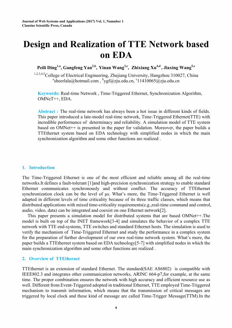
Fig.7 Presents the results of Gate Level simulation. As we can see, the system comes to the synchronized state in the second integration cycle, at time of 127μs.As it is operated in software simulation, no wire delay and any other uncertain facts, the error of synchronized can reach 0.
12
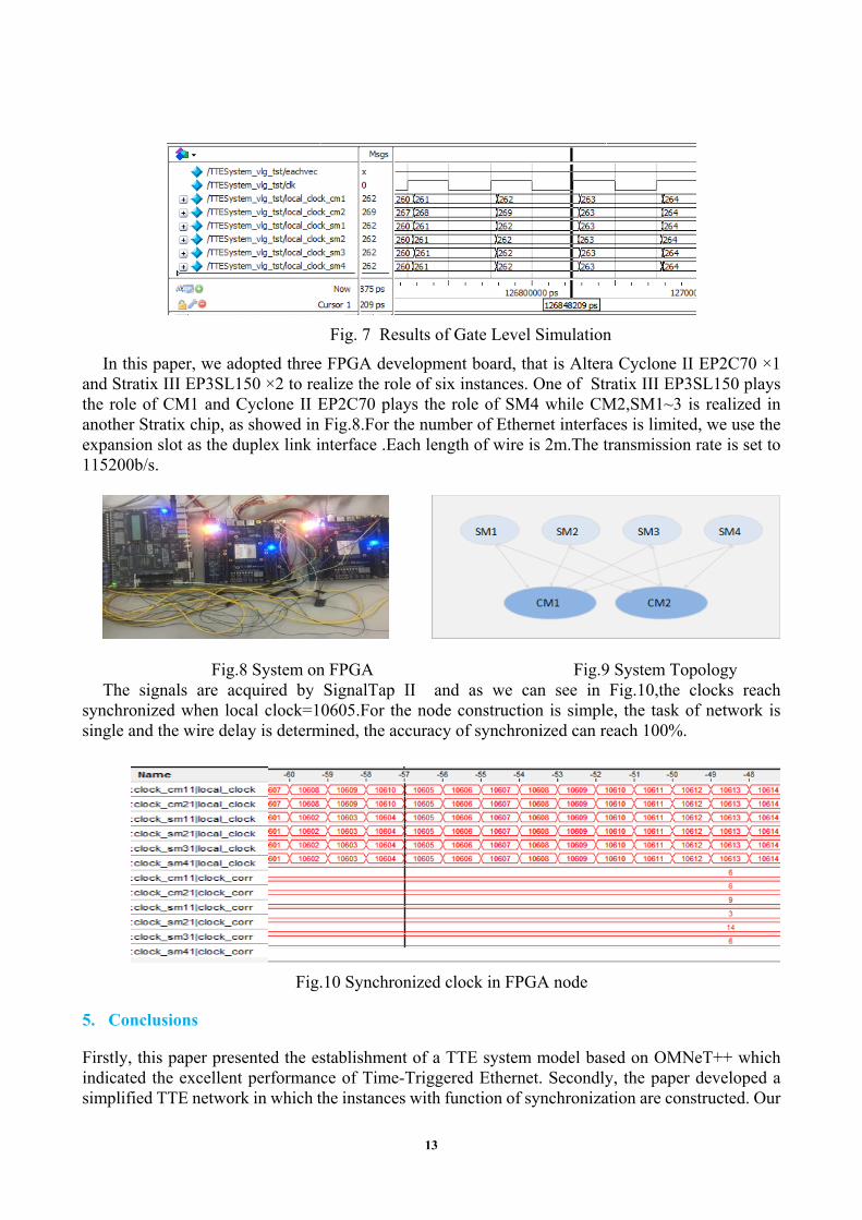
Fig. 7 Results of Gate Level Simulation
In this paper, we adopted three FPGA development board, that is Altera Cyclone II EP2C70 ×1 and Stratix III EP3SL150 ×2 to realize the role of six instances. One of Stratix III EP3SL150 plays the role of CM1 and Cyclone II EP2C70 plays the role of SM4 while CM2,SM1~3 is realized in another Stratix chip, as showed in Fig.8.For the number of Ethernet interfaces is limited, we use the expansion slot as the duplex link interface .Each length of wire is 2m.The transmission rate is set to 115200b/s.
Fig.8 System on FPGA Fig.9 System Topology The signals are acquired by SignalTap II and as we can see in Fig.10,the clocks reach
synchronized when local clock=10605.For the node construction is simple, the task of network is single and the wire delay is determined, the accuracy of synchronized can reach 100%.
Fig.10 Synchronized clock in FPGA node
5. Conclusions
Firstly, this paper presented the establishment of a TTE system model based on OMNeT++ which indicated the excellent performance of Time-Triggered Ethernet. Secondly, the paper developed a simplified TTE network in which the instances with function of synchronization are constructed. Our
13

future work is to integrate the designed instances with standard Ethernet and therefore develop our own TTE product. The synchronization algorithm will be improved in our real-time network, for example, the frequency error can be corrected and the role of node can be adapted automatically.
References
[1] Kopetz H, Ademaj A, Grillinger P, et al. The Time-Triggered Ethernet (TTE) Design. Eighth IEEE International Symposium on Object-Oriented Real-Time Distributed Computing. IEEE Computer Society, 2005:22-33.
[2] SAE Technical Standard.SAE AS6802. SAE International.2011-11.
[3] Steinbach T, Kenfack H D, Korf F, et al. An Extension of the OMNeT++ INET Framework for Simulating Real-time Ethernet with High Accuracy.International ICST Conference on Simulation TOOLS and Techniques. 2011:375-382.
[4] Knezic M, Ballesteros A, Proenza J. Towards Extending The Omnet++ INET Framework For Simulating Fault Injection In Ethernet-Based Flexible Time-Triggered Systems. 2014:1-4.
[5] Guilford John. Design of an FPGA-Based Hardware IEEE1588 Implementation.IEEE-1588 Conference and Plug-Fest, 2005-10 .
[6] Steinhammer K, Ademaj A. Hardware Implementation of the Time-Triggered Ethernet Controller.Embedded System Design: Topics, Techniques and Trends. Springer US, 2007:325-338.
[7] Kopetz H, Ademaj A, Grillinger P, et al. The Time-Triggered Ethernet (TTE) Design. Eighth IEEE International Symposium on Object-Oriented Real-Time Distributed Computing, 2005: 22-33.
[8] Steiner W, Bauer G, Hall B, et al. TTEthernet Dataflow Concept. Eighth IEEE International Symposium on Network Computing and Applications. IEEE Computer Society, 2009:319-322.
14