Embed Size (px)
Citation preview

University of Dayton University of Dayton
eCommons eCommons
Honors Theses University Honors Program
Spring 4-2016
Design and Prototyping of a Variable Geometry Extrusion Die to Design and Prototyping of a Variable Geometry Extrusion Die to
Exhibit Significant Alteration of Shape Exhibit Significant Alteration of Shape
David C. Bell University of Dayton
Follow this and additional works at: https://ecommons.udayton.edu/uhp_theses
Part of the Mechanical Engineering Commons
eCommons Citation eCommons Citation Bell, David C., "Design and Prototyping of a Variable Geometry Extrusion Die to Exhibit Significant Alteration of Shape" (2016). Honors Theses. 80. https://ecommons.udayton.edu/uhp_theses/80
This Honors Thesis is brought to you for free and open access by the University Honors Program at eCommons. It has been accepted for inclusion in Honors Theses by an authorized administrator of eCommons. For more information, please contact [email protected], [email protected].

Design and Prototyping of a Variable
Geometry Extrusion Die to Exhibit
Significant Alteration of Shape
Honors Thesis
David C. Bell
Department: Mechanical Engineering
Advisors: David H. Myszka, Ph.D. and Andrew P. Murray, Ph.D.
April 2016

Design and Prototyping of a Variable
Geometry Extrusion Die to Exhibit
Significant Alteration of Shape Honors Thesis
David C. Bell
Department: Mechanical Engineering
Advisors: David H. Myszka, Ph.D. and Andrew P. Murray, Ph.D.
April 2016
Abstract Extruded parts are conventionally made by forcing melted plastic through a steel die having a fixed opening that matches the shape of the part. Plastic parts made by extrusion include weather stripping, PVC pipe, and composite lumber. Variable geometry dies can change their opening shape during the extrusion process. Developing shape-changing dies technology offers the possibility of making parts with varying cross-sections that currently need to be made through injection molding. This is desirable as, compared to molding, extrusion tends to be faster and less expensive. Variable geometry extrusion dies have been designed and prototyped by the University of Dayton research team that confirms the validity of the concept. This research explores the limits of this new technology by creating a die that has substantial movement of components that form the die opening. Acknowledgements I would like to thank Creative Extruded Products for their assistance in this research for producing and testing all of the dies that have come from the DIMLab.

Table of Contents
Abstract Title Page
Background 1
Prior Research 1
Design Process and Segment Creation 4
Assembly and Segment Adjustment 9
Specific Design Requirements 11
The Design 12
Conclusion 16
Bibliography 18

P a g e | 1
1) Background
Over the past 40 years, polymer processing has increased at a rate of 5.6% annually
[1]. This growth is more than ten times the growth of steel and more than doubles the
growth of aluminum over the same period of time. Extrusion accounts for 40% of all
polymer production. Extrusion is such a common method of production because of its
low cost and high production rates relative to other methods [2-5]. Because of its
production benefits, it continues to grow as one of the most commonly used
manufacturing processes.
Extrusion is a relatively simple process in which a polymer is melted and forced to
flow through a die which shapes the polymer into the shape of the die [6-8]. After the
polymer exits the die it is cooled back to solid form and is cut to the appropriate size [9].
The product has a constant cross section of the shape of the die [10-13]. Although a
constant cross section is valuable for many production purposes, a variable cross section
would allow for a wider variety of products to take advantage of the cost savings
associated with extrusion. Variable geometry dies are currently not being used
significantly in manufacturing but research has begun [14, 15]. This research continues
the work that has been done through the Design of Innovative Machines Laboratory
(DIMLab), within the Department of Mechanical and Aerospace Engineering to
determine if the variable geometry extrusion die model works and determine its
limitations.
2) Prior Research
The difficulties with a variable geometry die are associated with its moving parts. A
variable geometry die needs to be designed to minimize or control leakage [16]. Leakage
is the polymer that gets in between the moving parts of the die. Leakage that does occur

P a g e | 2
needs to be removed or addressed so it does not destroy the system [17]. A variable
geometry die should have a die exit plane. A die exit plane limits the shape of the
extruded product beyond the limitations of the die [8]. Similarly, the die will need to be
covered with a face plate to prevent polymer from getting behind the rigid bodies making
up the edges of the die. Effectively, the face plate limits the application of polymer onto
the die, the die then shapes the polymer, lastly the polymer exits through the exit plane.
The face plate’s interference with the cross sections of the die should be minimal because
it will prevent the polymer from matching the shape of the die and will provide a poor
surface finish. Although not a necessary characteristic, having a constant cross sectional
area helps to make the design of a variable geometry die easier as the volumetric flow
rate does not need to be adjusted to keep the velocity constant. All prior dies have had
this characteristic. The final characteristic that needs to be taken into consideration is the
actuation of the device. Because it is a moving device, by definition it requires at least
one degree of freedom. A single degree of freedom solution would be preferred but is not
a necessary component of design [18]. In a previous die, multiple degrees of freedom
were used. This created a much larger design space and die land region, making it
difficult to protect all of the gaps. In order to create more complex geometries, multiple
degrees of freedom will be necessary, but will likely require limitations on the allowable
paths. Similarly, these moving parts cannot approach a kinematic singularity, as this
would cause the extrusion to fail. Smooth transitions between geometries are necessary.
Based on the design characteristics described, certain joints were determined to be
better in the design of a variable extrusion die. The two primary joints are crescent joints
and prismatic joints [18]. These two types of joints distinguish themselves because of

P a g e | 3
surface on surface contact. Surface on
surface contact is ideal for limiting
leakage. A crescent joint (shown in
Figure 1) uses a tongue piece that fits
into a groove on the other segment.
Because of the design of a crescent joint,
they only work within a range of angles
before two planes contact. Using the
contact these planes make can help
the design stay in the desired
arrangement. Crescent joints are also
inferior to corner joints because of the
required curved area surrounding the
joint; they cannot create a sharp
angle. Prismatic joints also use surface on
surface contact. Sliding joints (Shown in
figure 2) will serve as a necessary component
in variable geometry dies as they are
necessary for any component to have a
variable side length; without them
possibilities are very limited. A third type of
joint that appears to be possible in variable
geometry dies (although not used in this research) is corner joints (shown in figure 3).
Figure 1: Crescent Joint
Figure 2: Prismatic/Sliding Joint
Figure 3: Corner Joint

P a g e | 4
Corner joints have the advantage of offering a sharp corner to the geometry. Corner joints
contain a center of rotation at the corner of the shape. Corner joints rely on edge on edge
contact and therefore have more inherent potential for leakage [18]. Corner joints have
been used in simple shape changing die prototypes but only under the condition one of
the components was grounded. Due to the unknown nature of the efficacy of moving
corner joints, they were not used in this research.
The face plate prevents polymer flow from reaching gaps between segments. The face
plate at times may need to cover the cross section of the die from which polymer is
supposed to flow in order to prevent leakage of the polymer in a different orientation of
the die. This should be avoided as much as possible. The interference from the die plate
creates very poor surface quality as evidenced by the samples taken from both the
crescent-corner-prismatic die and the scraper die. The shape also will not closely follow
either the face plate or the die cross section, creating unpredictable results. The face plate
still must protect the gaps from leakage. Leaving at least 0.04” space between the face
plate perimeter and any gaps was the standard followed in this research.
3) Design Process and Segment Creation
Designing unique variable geometry dies is a new concept. Throughout the design
process in this research, the process changed as issues were discovered and solved. The
process described will explain the recommended way to create a variable die using only
crescent joints and sliding joints. When designing a die, limit the total cross sectional area
of the die to a few square inches. The polymer extruder the DIMLab uses, typically,
works with smaller parts and does not have the capacity to get much larger.

P a g e | 5
The first step in making a new design is to design the kinematic system of revolute
joints and prismatic joints only (methods for other joint types have not been established).
In this research the kinematic design was created in the sketch feature of Solidworks. The
kinematic design will not only determine the shape of the final profiles, but will also
require important characteristics regarding the plausibility of the design. This kinematic
structure will be able to display singularities, die area variability, potential joint
interference, and degrees of freedom. These characteristics need to be considered in this
step to create a satisfactory design based off specific design criteria. From the kinematic
structure, the desired activation limits can be determined. The activation limits will show
the range of motion and the initial, final and intermediate cross sectional shapes. The
kinematic structure should consist of a set of segments connected consecutively that will
never run into each other. The region between these connected pieces will be the die
opening. The angles between the segments should be kept fairly large to avoid
approaching a geometric singularity which would make it difficult for polymer flow. The
limits for how small these angles can get has not been determined.
One possible way to develop the kinematic design is to start with a simple kinematic
design (of maybe 3 segments) and repeatedly break segments into more pieces while
adding linkages to control the added segments. This allows the design to slowly gain
more complexity and to be able to add basic features one at a time. This process will
probably struggle creating precise cross sections for functional purposes, but is effective
for prototypes.
Once the kinematic design is set, the individual pieces should be created. The
following paragraphs will describe how to create a similar design in Solidworks. The first

P a g e | 6
step for any piece is to create the construction lines to match the dimensions from the
kinematic sketch. Once the construction lines are in place, the physical shapes can be
determined. Any piece making up part of the perimeter of the die region will require
either a crescent or prismatic joint at both ends. To make a crescent joint, start by making
two construction circles centered at the corner of the segment that requires a revolute
joint. The two circles will be the size of the inner and outer diameters of the crescent
joint. In this research, an inner diameter of 0.20” and an outer diameter of 0.60” were
used for all crescent joints. Make sure the male and female parts of the crescent joint
have the same dimensions. Add these construction circles to all of the crescent joints on a
part. Also add circles to any point that will be attached to a segment not making up the
perimeter. After this begin adding the complexities to the crescent joint. If the segment in
question is a male piece, add three lines connecting the two circles, drawn radially from
the center. The first segment will mark the end of the male segment or tongue. The
second will mark the beginning of the tongue and should be a construction line. The third
will mark the direction of the rest of the piece. The third line is only necessary if a
geometric constraint is desired apart from the tongue and groove contact. Each of these
line segments should be dimensioned as angles relative to the construction lines. The
dimensions of these angles are unknown at this time and will require adjustment later;
this is why it is imperative to dimension these relative to the construction lines, so they
easily can be changed without distorting the rest of the part. Once these construction line
segments are added, two arcs can be made. The first arc will follow the larger
construction circle, starting at the first line segment and ending at the second line
segment. The second arc will follow the smaller construction circle, starting at the first

P a g e | 7
line segment and ending at the third line segment.
This setup shown in figure 4 provides the contour of
the male crescent joint. The rest of the part can be
designed starting at the end of the outer arc and the
end of the third radial line segment.
If the corner of the segment is female a similar process is used. There should
already be two construction circles in place. Connect these construction circles with three
line segments. The first will mark the beginning of the female part or groove and should
be a construction line. The second will mark the end of the groove. The third line will
mark the direction the part will face, again only
necessary if a hard stop or geometric constraint is
desired apart from the tongue and groove interaction.
Two arcs should be made. The first arc follows the
larger construction circle and connects the first line
segment to the second. The second arc follows the
smaller construction circle and connects the second
line segment to the third line segment going through the first line segment on the way.
Each of the line segments should be dimensioned relative to the initial construction
geometry to allow the dimensions to be easily adjustable. This setup for the female
crescent joint is shown in figure 5. The rest of the part can be designed starting at the end
of the outer arc and the end of the third radial line segment.
With the structure of the crescent joints, the two structures can be attached. This
contour can be adjusted to create the features of the perimeter of the die. When
Figure 4: Male Crescent Joint Sketch
Figure 5: Female Crescent Joint

P a g e | 8
dimensioning these lines, keep in mind, the dimensions of the crescent joint angles will
need to be adjusted later. Any geometry referencing these features will change as the
angles are adjusted. The part of the segment not making up the perimeter of the die also
needs to be connected. If there is another joint interacting with this part, include the circle
marking this joint drawn earlier in the area connecting the two crescent joints. The shape
of this side at this point only needs to consider maintaining enough thickness to not break
when force is applied and making the shape look reasonable.
If a segment includes a sliding joint, at this point, the line of action will need to be set
back in the kinematic diagram so the sliding joint does not interfere with the crescent
joints. Once this kinematic issue is resolved, draw a construction line along the line of
slide. This line can be straight or curved. In this design a straight line of slide was used.
On the female half of the joint, this line does not need to be a construction line. Start by
making this line significantly larger than it needs to be, about three times a typical side
length. This will be shortened later. At the end of this line draw a perpendicular line away
from what will be the perimeter of the die. This line needs to be long enough to contain
the size of the groove desired. Once this line is complete, it can be connected to the
crescent joint used on the other end.
If the sliding joint is to be the male part or tongue, the construction line will become a
solid line connecting both sides of the crescent joint together. Most of this feature will be
added in a later extrusion. Make sure there is a face that is perpendicular to the line of
slide to create this feature.
At this point, the shape of every segment is complete. Extrude the 2D sketch out a
fixed distance. If the piece includes part of a sliding joint, add the features now. The male

P a g e | 9
and female parts of a sliding joint require the same sketch for them to interact. If the
piece is the female part of a sliding joint, draw the sketch into the face perpendicular to
the line of slide. Make an extruded cut of this shape through the whole part. Make sure
this sketch does not interfere with any other features. If the piece is the male part of a
sliding joint, draw the sketch on a plane perpendicular to the line of slide off of the part.
This sketch will be extruded creating a new feature with added material. This extrusion
should be about three times a typical side length, it will be shortened later.
Use the process described above to create all of the segments. Once all of these pieces
are created, make a plate that will act as the back piece. This back piece should be large
enough to fit the entire assembly. On this piece create circular features at all of the fixed
references in the kinematic design. Extrude this piece out (about 0.1”) to create a large
plate. This will be the fixed piece in the assembly. If it has not already been done, create
any segments attaching pieces not involving the perimeter of the die. At this point, they
can all be straight lines or solid shapes with circular features centered at the joints.
4) Assembly and Segment Adjustment
At this point, the assembly should be able to be constructed. The first piece added
should be the back piece or face plate. Fix this piece in place. Then start adding other
pieces. The primary mating tools should be concentric circles and concentric planes.
These mates emphasize the surface on surface contact requirement. Do not add limits on
the range of motion into these constraints. Once all of the pieces are attached, the basic
assembly should be complete. Confirm the current assembly is the desired arrangement
for these pieces. A kinematic diagram when assembled can have many configurations;
make sure the configuration in place is able to smoothly transition to the desired
configurations. Once this is confirmed, go back and fix the angular dimensions of the
P a g e | 10
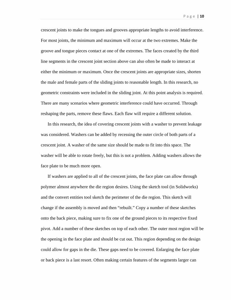
crescent joints to make the tongues and grooves appropriate lengths to avoid interference.
For most joints, the minimum and maximum will occur at the two extremes. Make the
groove and tongue pieces contact at one of the extremes. The faces created by the third
line segments in the crescent joint section above can also often be made to interact at
either the minimum or maximum. Once the crescent joints are appropriate sizes, shorten
the male and female parts of the sliding joints to reasonable length. In this research, no
geometric constraints were included in the sliding joint. At this point analysis is required.
There are many scenarios where geometric interference could have occurred. Through
reshaping the parts, remove these flaws. Each flaw will require a different solution.
In this research, the idea of covering crescent joints with a washer to prevent leakage
was considered. Washers can be added by recessing the outer circle of both parts of a
crescent joint. A washer of the same size should be made to fit into this space. The
washer will be able to rotate freely, but this is not a problem. Adding washers allows the
face plate to be much more open.
If washers are applied to all of the crescent joints, the face plate can allow through
polymer almost anywhere the die region desires. Using the sketch tool (in Solidworks)
and the convert entities tool sketch the perimeter of the die region. This sketch will
change if the assembly is moved and then “rebuilt.” Copy a number of these sketches
onto the back piece, making sure to fix one of the ground pieces to its respective fixed
pivot. Add a number of these sketches on top of each other. The outer most region will be
the opening in the face plate and should be cut out. This region depending on the design
could allow for gaps in the die. These gaps need to be covered. Enlarging the face plate
or back piece is a last resort. Often making certain features of the segments larger can

P a g e | 11
accomplish this, but the solution is not fully formed yet. Using a technique of copying
traced sketches onto the face plate has been an effective process for accomplishing this.
Once the gaps are covered, the segments not forming the perimeter need to be
redesigned to be able to interact with the other segments geometrically. The face plate
should be sized appropriately, trying to minimize the overall size of the die. The face
plate then should be built up vertically to act as a container for the die. Other finishing
touches should be made as necessary to make the die functional.
5) Specific Design Requirements
The primary purpose of this research was to discover the plausibility of creating a
variable geometry die with significant shape change. The orientations were allowed to be
designed not for any particular function, but rather just to show significant change.
Previous dies created for polymer extrusion have all been simple in geometric change and
kinematic complexity. This research looked into creating a die with at least six different
segments making up the perimeter. In order to prove the concepts plausibility, some of
the features were controlled by using techniques already discovered. For this reason, only
crescent joints and sliding joints were used. Also, multiple degree of freedom systems
have run into difficulties with the size of the region from which the die can flow. This
research limits designs to single degree of freedom solutions. From previous dies it has
been discovered that face plate interference creates poor finished quality. For this reason
it was avoided. The die was limited to about 1 square inch of total area. This is a
requirement for being used in the polymer extruder intended to be used. The die itself
will use as many positive stops or geometric limits intended to increase the stability of
the design. Finally, the design was to be one inch thick. The possibility of a longer die

P a g e | 12
including heating along the die was discussed, but ultimately thrown out because of the
unnecessary added complexity. The die was designed to contain no sharp corners. All of
the angles making up the perimeter of the die were designed to have smooth transitions.
This was a request to allow the results from this die to be used in other research.
6) The Design
The design developed
in this research shown in
figure 6 is the current
design of what will be a
prototype for variable
geometry extrusion. The
extreme orientations are
shown in figures 7 and 8.
From these views, it can be seen
that the profiles do not serve a
functional purpose. The profiles
were intended to vary greatly and
the actual shape of these profiles
was unimportant. The design will
transition between these two
profiles while going through
intermediate profiles along the way.
The final extruded polymer part will
Figure 6: Variable Geometry Die Assembly
Figure 8: Variable Geometry Die Extreme Profile 2
Figure 7: Variable Geometry Die Extreme Profile 1

P a g e | 13
look similar to the part shown in
figure 8.
The design created is a one
degree of freedom system driven by
the blue segment shown in figure 6, 7
and 8. The design has six segments
making up its perimeter. The design includes five crescent joints and one straight line
sliding joint. The design is 1 inch thick. All of the Crescent joints are the same size. All
of the crescent joints are covered with washers. Using washers should eliminate the
concern of the gap created between the tongue and groove of the crescent joints. To add
washers and keep the necessary constant flat surface for the polymer to contact, the
tongue and groove of crescent joints need to be recessed. In this design, the crescent
joints were recessed 0.05 inches and a washer of the same size fills the hole. One problem
with the current design comes from this added feature. The purple segment requires this
cutout for the washer to prevent a geometric constraint, but because it is part of a sliding
joint this cutout will not always be
fully covered by the washer. This flaw
is shown in figure 10. Figure 10 is a
close up of the die shown in figure 6.
This creates a gap through which
polymer can flow. This gap will need
to be addressed before this die will be
Figure 9: Variable Geometry Die Contour Model
Figure 10: Washer Indent Leakage Flaw

P a g e | 14
usable. One possible solution would be to once again move the sliding joint to a parallel
line of slide farther away from the revolute joint.
The washers allow for the face
plate to be larger because the face
plate does not need to cover the gaps
the crescent joints create. The face
plate in this design is the perimeter
of all of the area the polymer would
flow. This face plate is ignoring the
gaps created behind the segments.
This current design will allow for
leakage between the blue and brown segments. This gap is shown in figure 11. This gap
occurs because of how much the position of the nearby crescent joint physically moves.
One potential solution to this problem would be to make the crescent joint at this point
larger, allowing for a larger washer that would cover this point. A larger crescent joint
would impose more of its geometry on the die exit shape which could be undesirable in
certain situations. The allowable movement of the location of revolute joints appears to
be related to the size of the crescent joint used.
The face plate blocks polymer flow slightly near the yellow segment. Some of this
material is unnecessary with the addition of the washers protecting the areas this material
was intended to block. The yellow piece moves significantly and some of the face plate
may be needed to cover the gaps in some of the intermediate orientations. This
unnecessary material is shown in Figure 12.
Figure 11: Leakage gap Behind Crescent Joint

P a g e | 15
The yellow segment is the smallest piece
included in the die perimeter. The size of the
portion of this segment included in the
perimeter is about 0.81 inches. Connecting the
two crescent joints in this segment was
difficult because of the limited about of space
to work. The minimum size of a segment appears to be limited based off the size of the
crescent joints used. Both of the crescent joints have an outer radius of 0.3 inches.
Because these circles cannot overlap and will need to be attached, the smallest segment
involved in the perimeter of the die needs to be larger than the sum of the radii of the two
crescent joints it uses. It is recommended the segment is a substantial amount larger than
this limit.
The sliding joint was a requirement for this design. The sliding joint in this design
moves within a relatively small range. This limited range may not display all of the
information that it could. Only one previous die included a sliding joint. Difficulties
resulting from sliding joints are currently unknown and this die is intended to display.
This is not an easily fixable problem. In order to make this feature move a greater
distance the entire design would need to be remade.
Within Solidworks, with the current design fully constrained, the die sometimes will
move into a different orientation with the same input angle from the blue piece. This
could represent a kinematic singularity. This possible singularity could be simply a glitch
in the software that would not occur in the physical world. The number of positive stops
in this design should make the kinematic singularity impossible to reach. If this kinematic
Figure 12: Unnecessary Face Plate Material

P a g e | 16
singularity is determined to be a significant concern, the kinematic design would need to
be edited.
7) Conclusion
This research looked into the design of a prototype of a variable geometry extrusion
die. The primary findings of this research involved the method and limitations of variable
geometry dies. The largest design factor when creating a die appears to be the size of the
crescent joints used. Assuming crescent joints are the only way revolute joints will be
represented, the size of the crescent joints has a large impact on the amount of shape
change and types of segments used. The use of washers to cover crescent joints seems to
be a very good method of preventing leakage. The prototype once built will be able to
confirm the feature as a plausible solution.
The prototype once built will help further define the possibilities and limitations of
variable geometry extrusion. A variable geometry die designed for functionality will have
features requiring a greater number of segments and joints more similar to this die than
previous dies. Discovering the limitations of the design will help further clarify the types
Figure 14: Knife Handle Extrusion Die Prototype Figure 13: Knife Handle Extrusion Die Prototype

P a g e | 17
of items that could eventually use variable geometry dies for manufacturing. The die
shown in figure 14 is an example of a die with a valuable function. This die creates the
profiles necessary to create the knife handle shown in figure 13. This shows the potential
of shape changing dies.
The next steps for advancing this research require completing a die with the flaws
that were mentioned addressed and then creating that die. This die has features previous
dies have not included; these features need to be shown to be possible. Long term, when
looking at potential future dies, the biggest concern appears to be being able to deal with
all of the limitations surrounding crescent joints. Crescent joints if too small can allow for
leakage behind them if the particular piece moves significantly, but limits the size of
segments and the possible shapes of the profile. These profiles are forced to contain the
circular portion created by crescent joints, adding a shape that might not be desirable. The
smaller the crescent joints, the smaller this feature. To try to make the crescent joints
smaller, exploring the possibility of adding a flexible material to cover the gap behind the
crescent joint (like the one shown in figure 11) could allow for better finished profiles.
The knife handle die shown in figure 14 has multiple degrees of freedom; most dies
created for functional purposes will likely use multiple degrees of freedom. Solving the
problems surrounding multiple degrees of freedom seems to be important research to
discover for the future of the field.

P a g e | 18
8) Bibliography
1] Biron, M., Thermoplastics and Thermoplastic Composites: Technical Information for Plastics Users Elsevier Ltd., 2007. [2] Muccio, E., Plastics Processing Technology, ASM International, Materials Park, OH, 1994. [3] Milacron Manufacturing Technologies, The Single Screw Series PAK , web, 2014. [4] Rosato, D. V., Die Design and Performance, Extruding Plastics, Chapman & Hall, pp. 228- 82, 1998. [5] The Ferdonia Group, Extruded Plastics to 2013, Cleveland OH, 2009. [6] Rauwendaal, C., 2001, Polymer Extrusion, 4th ed., Hanser, Munich, Germany. [7] Levy, S., 1981, Plastics Extrusion Technology Handbook, Industrial Press. [8] Kostic, M. M., Reifschneider, L. G., 2006, Design of Extrusion Dies, Encyclopedia of Chemical Processing, pp. 633-649. [9] Michaeli, W., 1984, Extrusion Dies, Design and Engineering Computations, Hanser, Munich, Germany. [10] Covas, J. A., Carneiro, O. S., Brito, A. M., 1991, Designing Extrusion Dies for Thermoplastics, Journal of Elastomers and Thermoplastics, vol. 23, pp. 218-238. [11] Tadmor, Z.; Gogos, C. G., 1979, Die Forming: Principles of Polymer Processing, John Wiley & Sons, pp. 521-524. [12] Sun, Y., 2006, Optimization of Die Geometry for Polymer Extrusion, Ph.D. Dissertation, Michigan Technological University. [13] Michaeli, W., 1992, Extrusion Dies for Plastics and Rubber, Hanser Publishers, New York. [14] Yukihiko, Y., Yoichi, H., 1993, Method of Manufacturing Automotive Windshield Molding, United States Patent, 5229054. [15] Toyoda-Gosei, 2004, Development of Body Sealing Products, web. [16] Panchal, R. R., Kazmer, D., 2007, Characterization of Polymer flows in Very Thin Gaps, Proc of ASME International Manufacturing Science and Engineering Conference, paper no. MSEC2007-31108. [17] Gander, J. D., Giacomin, A. J., 1997, Review of Die Lip Buildup in Plastics Extrusion, Polymer Engineering and Science, vol. 37, no. 7, pp. 1113-1126. [18] Giaier, K. S., Myszka, D. H., Kramer, W. P., and Murray, A. P. Variable Geometry Dies for Polymer Extrusion, Proceedings of ASME 2014 International Mechanical Engineering Congress & Exposition, IMECE2014-38409.