Embed Size (px)
Citation preview
Journal of Engineering and Technology (JET) Vol8, No. 1 February 2013
Falalu, R. J. & Jatau, J.S pp 1- 12 1
DESIGN AND PRODUCTION OF SINGLE-THROW NODULAR CAST IRON
CRANKSHAFT
1Falalu, R.J. And
2Jatau, J.S.
1Department of Agricultural Engineering, Bayero University Kano, Nigeria, Email address:
2Mechanical Engineering Programme, Abubakar Tafawa Balewa University, Bauchi,
Nigeria
ABSTRACT
The design, casting and mechanical test of single-throw ductile cast iron crankshaft is presented. Sand casting
technique, with side gating system (riser contact in cope) was adopted. The ductile cast iron material was
produced by inoculating molten iron (which contains sufficient amount of silicon) in the ladle. This was
accomplished by adding small amount of magnesium in the form of magnesium ferrosilicon alloy (5% Mg, 45%
Si, rest iron) into the ladle melt which resulted to nodularization of the free graphite carbon. The inoculants
were introduced into the melt by sandwich method. Crankshaft was then cast at different pouring temperature
and time. Mechanical properties test was conducted on the as- cast and annealed samples. Results show that
best quality crankshaft can be produced at pouring temperature and time ranges of 1400- l415°C and 7-12
seconds respectively. Values of tensile strength, hardness and percent elongation for the as-cast samples were
on the average found to be 620 N/mm2, 300BH and 4.5% respectively while for the heat treated samples the
corresponding values were 500 N/mm2, 205BH, 12%. Also impact strength was found to be 13.0 J. On
comparison, the mechanical properties were found to be in good agreement with that of forged/machined steel
crankshaft material (773 N/mm2, 18% and 225-235BH) with even better hardness property in the as-cast
condition.
Significance: The production of vehicle parts such
as crankshaft is one of Nigeria’s objectives in its
policy of transfer of technology. This will solve the
problem of relaying so much on imported costly
parts hence improve the country scarce foreign
reserve.
Keywords: Single-throw crankshaft, Nodular cast
iron, Casting process, Sandwich method, Inoculation,
Mechanical properties
.
Journal of Engineering and Technology (JET) Vol8, No. 1 February 2013
Falalu, R. J. & Jatau, J.S pp 1- 12 2
1. INTRODUCTION
The need to produce engine parts for vehicles and
industrial machines locally has come-of age long
before now, especially if one considers the
tremendous increase in the cost of imported
machines and their spare parts. Along this line, the
Federal Government set up centre for Automotive
Design and Development (CADD) at Ahmadu Bello
University, Zaria with the sole motive of producing
and developing automobiles locally. On the same
vain the National Automotive Council Degree No.
84 was promulgated in 1993. Though there is now a
remarkable progress in the production of engine
parts, yet much have not been done in the area of
engine crankshafts (Falalu, 2003). This could be
attributed to the fact that crankshaft, being the
most stressed engine part, requires special skill,
techniques and equipment to produce.
Conventionally, crankshafts are produce from steel
material by drop forging in dies or machined from
solid steel. These processes are however, very
expensive because of high initial capital investment
and machining cost, especially in the procurement of
the dies. Hence, there is a need for an alternative
process which will compete with the conventional
methods at a relatively less expense. Of the various
metals forming processes existing, casting process
proved to be the best alternative to forging and
machining for crankshaft production. This is because
articles of intricate shapes and desired dimensions
with specified properties are easily produced directly
from molten metal with less expenditure of energy,
material and labor. In fact, the process (casting)
design flexibility and versatility have motivated the
automobile industries to adopt casting as a better
alternative process for manufacturing most of their
engine components. However, in substituting forging
with casting process for crankshaft production, the
restrictive limitation here is the poor casting
properties of the conventional material (i.e. steel).
Steel usually makes a rough looking casting; reduces
in size substantially due to solidification shrinkage
(about 2 to 3%) and thermal contraction as the
casting cools to room temperature. The difficulty to
control carbon in cast steels also has been a set-back,
since its strength is primarily a function of the carbon
content. The alternative material is undoubtedly
ductile cast iron.
Ductile cast iron family possesses high casting
properties, ease of machining, reliability in service,
vibration damping, surface hardenability and wide
range of strength. With a pearlitic matrix, ductile
iron can have strength up to 120, 000 psi (829,392 x
103 N/m
2) which is equivalent to the strength of
high-carbon-steel but with superior castability and
machinability (Niebel et al., 1989). And with a
completely ferritic matrix, ductile iron can have
minimum percent elongation value of 17% and
tensile strength (minimum) of 370 N/m2. Still with
mainly ferritic matrix, ductile iron can have percent
elongation (minimum) of 12% and tensile strength
(minimum) of 420 N/m2 (Davies, 1983). Since
modulus of elasticity of ductile iron is relatively
lower than that of steel, the stresses due to
unavoidable misalignment are lower, hence suitable
for crank-shaft production.
Journal of Engineering and Technology (JET) Vol8, No. 1 February 2013
Falalu, R. J. & Jatau, J.S pp 1- 12 3
2. MATERIALS AND METHODS
2.1 Design considerations and calculations
Crankshaft of an engine, which is the most stressed
part, has to be designed for strength and stiffness
against bending and torsion stresses due to gas loads
and also to take care of stresses due to vibration
(Agrawal, 1974). It must also provide sufficient
bearing area to suit the bearing pressure. Other
requirements are minimum moving parts so as to
reduce stresses due to inertia forces, and surface
hardness since the crankpins and journals are
supported in bearings. However, crankshafts for
single cylinder engine are designed to withstand the
maximum bending stress, maximum shear stress and
combined stress (Agrawal, 1974).The maximum
bending moment is expected to occur when the
crankshaft is at top dead-centre (TDC) and maximum
shear stress will occur when the crank makes
approximately angle of 90° with the connecting rod.
Inertia forces developed in engine due to masses of
revolving and reciprocating parts (piston assembly)
act on the crankshaft and cause it to shake. These
forces are therefore balanced by attached balance
weights at the crank webs.
2.1.1 Crankpin diameter (dc): This is one of the
features of the crankshaft critical zone which support
the gas load due to combustion via a connecting rod.
Crankpin diameter is often designed to suit the
requirement of maximum bending and torsion
pressures due to gas load. To determine the
minimum crankpin diameter, the bending and
twisting moments due to the gas pressure load are
calculated. For simplicity, the crankshaft is
considered to be a simply supported beam with a
concentrated load at the centre.
The maximum force, F, on the crankpin can be
expressed as a function of gas pressure intensity and
cylinder diameter (Agrawal, 1974), thus:
𝐹 = 𝜋
4𝐷𝑝
2 𝑝 …. (1)
According to Nyler and Nyler (1987); Avallone and
Baumeister (1987):
𝑝 = 33,000𝐻𝑝 33,000𝐻𝑃
2𝑟𝐴𝑝 𝑁 (2)
The maximum bending moment, M, under the load F
may be calculated from the expression:
𝑀 = 𝐹𝐿
4 … (3)
Torque T, (in pound-inch) can be determined from as
suggested by Erik et al. (1982) using the expression:
𝑇 = 396000
2𝜋𝑁.𝐻𝑃 (4)
Where: F = maximum force due to gas pressure; Dp =
Piston diameter; Ap = Area of the piston; P = Gas
pressure intensity; r = crank radius specified as 28
mm; N= Engine speed specified as 3600 rpm; HP =
Engine horse power specified as 5 hp; L – center
distance between bearings, equals to 1.5D; Cylinder
bore, D for the engine is 67 mm; Piston- cylinder
clearance was taken as 0.1 mm
Journal of Engineering and Technology (JET) Vol8, No. 1 February 2013
Falalu, R. J. & Jatau, J.S pp 1- 12 4
Gas pressure was calculated as 3166.013 kN/m2;
maximum bending moment, M was found to be
27.77 N-m; and Torque, T = 9.91 N-m.
The crankpin minimum diameter was calculated
using the formula (Erik et al., 1982):
𝑑3 =5.1
𝑓𝑠 (𝑀𝐾𝑏)2 + (𝑇𝐾𝑡 )
2 (5)
Where: Kb = Kt = 1.5 (shock and fatigue factors);
factor of safety, fs = 2000 psi (138.2 MN/m2).
The minimum crankpin diameter was calculated to
be 25.36 mm, which agrees in totality with the
specification of the manufacturer (25.4 mm).
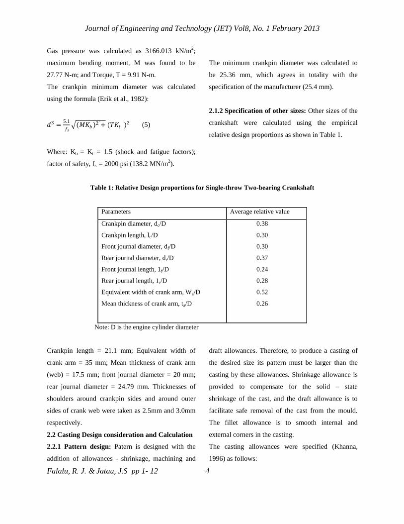
2.1.2 Specification of other sizes: Other sizes of the
crankshaft were calculated using the empirical
relative design proportions as shown in Table 1.
Table 1: Relative Design proportions for Single-throw Two-bearing Crankshaft
Parameters Average relative value
Crankpin diameter, dc/D
Crankpin length, lc/D
Front journal diameter, df/D
Rear journal diameter, dr/D
Front journal length, 1f/D
Rear journal length, 1r/D
Equivalent width of crank arm, Wa/D
Mean thickness of crank arm, ta/D
0.38
0.30
0.30
0.37
0.24
0.28
0.52
0.26
Note: D is the engine cylinder diameter
Crankpin length = 21.1 mm; Equivalent width of
crank arm = 35 mm; Mean thickness of crank arm
(web) = 17.5 mm; front journal diameter = 20 mm;
rear journal diameter = 24.79 mm. Thicknesses of
shoulders around crankpin sides and around outer
sides of crank web were taken as 2.5mm and 3.0mm
respectively.
2.2 Casting Design consideration and Calculation
2.2.1 Pattern design: Patern is designed with the
addition of allowances - shrinkage, machining and
draft allowances. Therefore, to produce a casting of
the desired size its pattern must be larger than the
casting by these allowances. Shrinkage allowance is
provided to compensate for the solid – state
shrinkage of the cast, and the draft allowance is to
facilitate safe removal of the cast from the mould.
The fillet allowance is to smooth internal and
external corners in the casting.
The casting allowances were specified (Khanna,
1996) as follows:
Journal of Engineering and Technology (JET) Vol8, No. 1 February 2013
Falalu, R. J. & Jatau, J.S pp 1- 12 5
- Shrinkage allowance = 20mm/m = 0.02;
- Machining allowance = 5mm ;
- Draft allowance = 3°
- Fillet radii = 10% of the section thickness.
The pattern dimensions were thus determined as
follows:
- Pattern crankpin diameter = 25.4 + 25.4x0.02 +
5 = 31 mm
- Pattern crankpin length = 20 + 0.02 x 20 = 20.4
mm
- Thickness of pattern crank arm = 17 + 1.7 = 18.7
mm
- Pattern rear journal diameter = 20 + 0.4 + 5 =
25.4 mm
- Pattern front journal diameter = 25 + 25 +
0.02+5 = 30.5 mm
- Fillet radii for pattern journals and crankpin are
4 mm (each) and 2mm respectively.
2.2.2 Gating design: The purpose of gating design is
basically to control the pattern of metal flow within
the mould. The design considers the avoidance of
sudden or right angle changes in the flow direction
and that the gating should form part of the pattern.
Based on the chosen moulding box (dimensions –
410 mm x 370 mm x 150 mm) available at
BAMFORDs foundry, Jos-Nigeria, the total height
of the sprue and pouring cup was set to be 130 mm.
The molten metal flow velocity at the sprue bottom,
Vsb is calculated from the expression (Nwajagu,
1994):
𝑉𝑠𝑏 = 2𝑔𝑐 … (6)
Where hc is the total available height for the sprue
and pouring cup = 130mm.
Dimensional characteristics of gating system for
ductile iron casting is given as (Khanna, 1996):
As: Ar: Ag = 10:9:8
Where; As = area of sprue, Ar = area of runner and
Ag = area of gate.
Since double gating was employed in this work, then
Ag = Ag/2 = 4, the ratio is now 10: 9: 4. The
diameter at mould cavity entry, that is gate section
(dg) was specified based on the flow velocity at the
section to be 30mm. Area of ingate, Ag is thus;
Ag = πdg2 / 4 = π30
2 / 4 = 706.86 mm
2 , and Ar =
9/4 Ag = 1590.4 mm2
; therefore, Ar = 1590.4
mm2.
Similarly, As = 1.1Ar = 1.1x1590.4 = 1767.1 mm2.
The diameters were thus obtained as: ds = 47.4 mm
and dr = 45.0 mm.
2.2.3 Riser design: The riser is design to provide
feed metal to the casting for the whole period of
solidification and to ensure directional solidification.
The minimum volume of riser, Vr, required is
calculated using the expression (Khanna, 1996)
𝑉𝑐
𝑉𝑟=𝑈−𝑆
𝑆 ….. (7)
Where: 𝑉𝑐 = volume of casting; U = percentage
shrinkage for a particular type of riser and equals
Journal of Engineering and Technology (JET) Vol8, No. 1 February 2013
Falalu, R. J. & Jatau, J.S pp 1- 12 6
14% for a cylindrical riser; S = specific shrinkage of
the alloy (%), and value of S for ductile iron alloy
material is 0.02 (Khanna, 1996).
Vc was computed from the casting dimensions to be
192 cm3. Riser volume, Vr is thus calculated as, Vr =
192 (0.14-0.02/0.02) = 32 cm3. Volume of the
cylindrical riser therefore equals 32 cm3. The riser
connection was made at the crank web section,
which is also the thickest portion of the casting.
2.3 Casting production
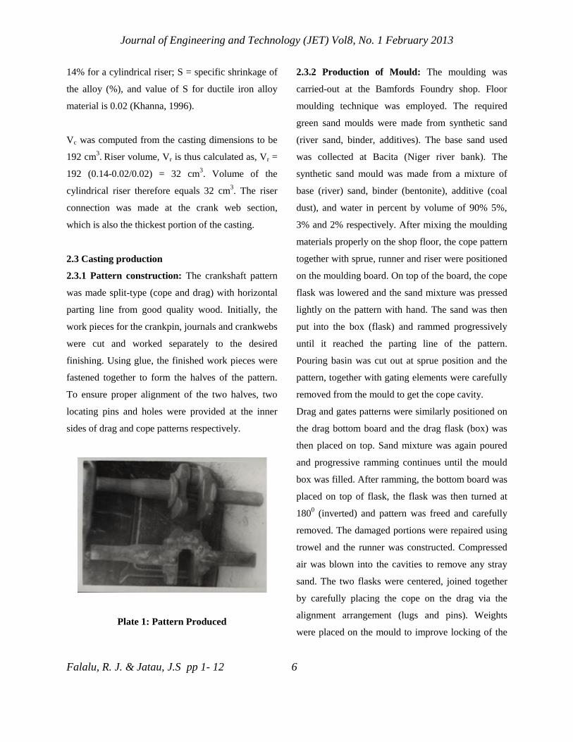
2.3.1 Pattern construction: The crankshaft pattern
was made split-type (cope and drag) with horizontal
parting line from good quality wood. Initially, the
work pieces for the crankpin, journals and crankwebs
were cut and worked separately to the desired
finishing. Using glue, the finished work pieces were
fastened together to form the halves of the pattern.
To ensure proper alignment of the two halves, two
locating pins and holes were provided at the inner
sides of drag and cope patterns respectively.
Plate 1: Pattern Produced
2.3.2 Production of Mould: The moulding was
carried-out at the Bamfords Foundry shop. Floor
moulding technique was employed. The required
green sand moulds were made from synthetic sand
(river sand, binder, additives). The base sand used
was collected at Bacita (Niger river bank). The
synthetic sand mould was made from a mixture of
base (river) sand, binder (bentonite), additive (coal
dust), and water in percent by volume of 90% 5%,
3% and 2% respectively. After mixing the moulding
materials properly on the shop floor, the cope pattern
together with sprue, runner and riser were positioned
on the moulding board. On top of the board, the cope
flask was lowered and the sand mixture was pressed
lightly on the pattern with hand. The sand was then
put into the box (flask) and rammed progressively
until it reached the parting line of the pattern.
Pouring basin was cut out at sprue position and the
pattern, together with gating elements were carefully
removed from the mould to get the cope cavity.
Drag and gates patterns were similarly positioned on
the drag bottom board and the drag flask (box) was
then placed on top. Sand mixture was again poured
and progressive ramming continues until the mould
box was filled. After ramming, the bottom board was
placed on top of flask, the flask was then turned at
1800 (inverted) and pattern was freed and carefully
removed. The damaged portions were repaired using
trowel and the runner was constructed. Compressed
air was blown into the cavities to remove any stray
sand. The two flasks were centered, joined together
by carefully placing the cope on the drag via the
alignment arrangement (lugs and pins). Weights
were placed on the mould to improve locking of the
Journal of Engineering and Technology (JET) Vol8, No. 1 February 2013
Falalu, R. J. & Jatau, J.S pp 1- 12 7
cope and drag flasks and made ready for pouring the
molten metal.
2.3.3 Charge material preparation, Melting, and
Ladle treatment: Raw materials used for furnace
charge were; pig iron, steel scrap, ductile iron return
scrap and high purity carburizer (graphite electrode).
The steel scrap was meant to increase the manganese
content which is low in pig iron while the carburizer
is to raise the graphite carbon content. These
materials were cleaned and blended together to get
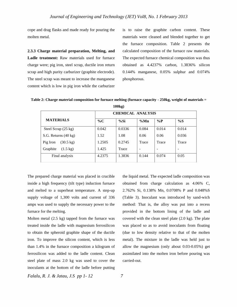
the furnace composition. Table 2 presents the
calculated composition of the furnace raw materials.
The expected furnace chemical composition was thus
obtained as 4.4237% carbon, 1.3836% silicon
0.144% manganese, 0.05% sulphur and 0.074%
phosphorous.
Table 2: Charge material composition for furnace melting (furnace capacity - 250kg, weight of materials =
100kg)
The prepared charge material was placed in crucible
inside a high frequency (tilt type) induction furnace
and melted to a superheat temperature. A step-up
supply voltage of 1,300 volts and current of 336
amps was used to supply the necessary power to the
furnace for the melting.
Molten metal (2.5 kg) tapped from the furnace was
treated inside the ladle with magnesium ferrosilicon
to obtain the spheroid graphite shape of the ductile
iron. To improve the silicon content, which is less
than 1.4% in the furnace composition a kilogram of
ferrosilicon was added to the ladle content. Clean
steel plate of mass 2.0 kg was used to cover the
inoculants at the bottom of the ladle before putting
the liquid metal. The expected ladle composition was
obtained from charge calculation as 4.06% C,
2.762% Si, 0.138% Mn, 0.0708% P and 0.048%S
(Table 3). Inoculant was introduced by sand-wich
method: That is, the alloy was put into a recess
provided in the bottom lining of the ladle and
covered with the clean steel plate (2.0 kg). The plate
was placed so as to avoid inoculants from floating
(due to low density relative to that of the molten
metal). The mixture in the ladle was held just to
allow the magnesium (only about 0.03-0.05%) get
assimilated into the molten iron before pouring was
carried-out.
MATERIALS
CHEMICAL ANALYSIS
%C %Si %Mn %P %S
Steel Scrap (25 kg)
S.G. Returns (40 kg)
Pig Iron (30.5 kg)
Graphite (1.5 kg)
0.042
1.52
1.2505
1.425
0.0336
1.08
0.2745
Trace
0.084
0.06
Trace
-
0.014
0.06
Trace
-
0.014
0.036
Trace
-
Final analysis 4.2375 1.3836 0.144 0.074 0.05
Journal of Engineering and Technology (JET) Vol8, No. 1 February 2013
Falalu, R. J. & Jatau, J.S pp 1- 12 8
Table 3: Material composition for ladle treatment (quantity of metal treated is 50 kg)
2.3.4 Casting of the crankshaft: The modified ladle
content (melt) was poured into the assembled moulds
through a pouring basin until both sprue and risers
were completely filled. Six castings at varied pouring
temperature and time were made. Before each
pouring, the temperature was determined using
immersion thermocouple. Stop watch was used to
determine the time taken for the melt to completely
fill a particular mould. Values were observed and
recorded accordingly.
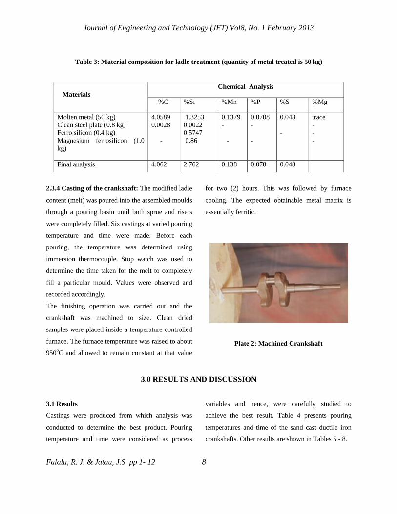
The finishing operation was carried out and the
crankshaft was machined to size. Clean dried
samples were placed inside a temperature controlled
furnace. The furnace temperature was raised to about
9500C and allowed to remain constant at that value
for two (2) hours. This was followed by furnace
cooling. The expected obtainable metal matrix is
essentially ferritic.
Figure 2.6: As-fettled
Plate 2: Machined Crankshaft
3.0 RESULTS AND DISCUSSION
3.1 Results
Castings were produced from which analysis was
conducted to determine the best product. Pouring
temperature and time were considered as process
variables and hence, were carefully studied to
achieve the best result. Table 4 presents pouring
temperatures and time of the sand cast ductile iron
crankshafts. Other results are shown in Tables 5 - 8.
Materials
Chemical Analysis
%C %Si %Mn %P %S %Mg
Molten metal (50 kg)
Clean steel plate (0.8 kg)
Ferro silicon (0.4 kg)
Magnesium ferrosilicon (1.0
kg)
4.0589
0.0028
-
1.3253
0.0022
0.5747
0.86
0.1379
-
-
0.0708
-
-
0.048
-
trace
-
-
-
Final analysis 4.062 2.762 0.138 0.078 0.048
Journal of Engineering and Technology (JET) Vol8, No. 1 February 2013
Falalu, R. J. & Jatau, J.S pp 1- 12 9
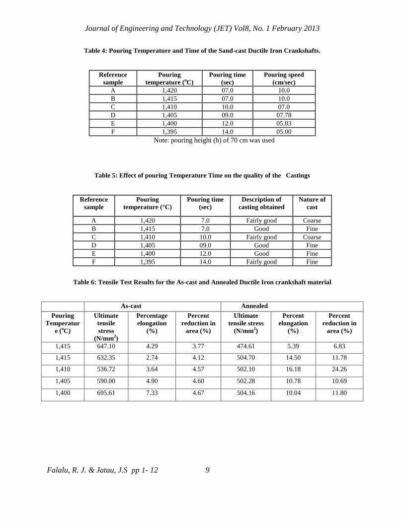
Table 4: Pouring Temperature and Time of the Sand-cast Ductile Iron Crankshafts.
Reference
sample
Pouring
temperature (oC)
Pouring time
(sec)
Pouring speed
(cm/sec)
A 1,420 07.0 10.0
B 1,415 07.0 10.0
C 1,410 10.0 07.0
D 1,405 09.0 07.78
E 1,400 12.0 05.83
F 1,395 14.0 05.00
Note: pouring height (h) of 70 cm was used
Table 5: Effect of pouring Temperature Time on the quality of the Castings
Reference
sample
Pouring
temperature (°C)
Pouring time
(sec)
Description of
casting obtained
Nature of
cast
A 1,420 7.0 Fairly good Coarse
B 1,415 7.0 Good Fine
C 1,410 10.0 Fairly good Coarse
D 1,405 09.0 Good Fine
E 1,400 12.0 Good Fine
F 1,395 14.0 Fairly good Fine
Table 6: Tensile Test Results for the As-cast and Annealed Ductile Iron crankshaft material
As-cast Annealed
Pouring
Temperatur
e (oC)
Ultimate
tensile
stress
(N/mm2)
Percentage
elongation
(%)
Percent
reduction in
area (%)
Ultimate
tensile stress
(N/mm2)
Percent
elongation
(%)
Percent
reduction in
area (%)
1,415 647.10 4.29 3.77 474.61 5.39 6.83
1,415 632.35 2.74 4.12 504.70 14.50 11.78
1,410 536.72 3.64 4.57 502.10 16.18 24.26
1,405 590.00 4.90 4.60 502.28 10.78 10.69
1,400 695.61 7.33 4.67 504.16 10.04 11.80
Journal of Engineering and Technology (JET) Vol8, No. 1 February 2013
Falalu, R. J. & Jatau, J.S pp 1- 12 10
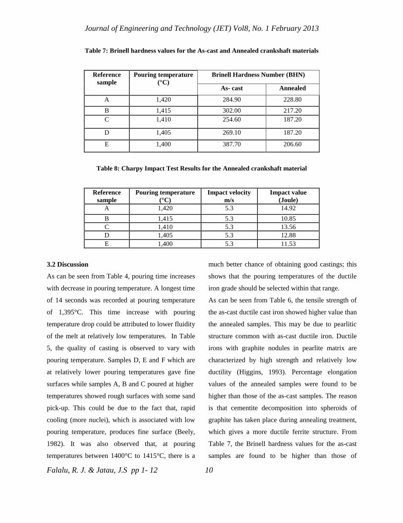
Table 7: Brinell hardness values for the As-cast and Annealed crankshaft materials
Reference
sample
Pouring temperature
(°C)
Brinell Hardness Number (BHN)
As- cast Annealed
A 1,420 284.90 228.80
B 1,415 302.00 217.20
C 1,410 254.60 187.20
D 1,405 269.10 187.20
E 1,400 387.70 206.60
Table 8: Charpy Impact Test Results for the Annealed crankshaft material
Reference
sample
Pouring temperature
(°C)
Impact velocity
m/s
Impact value
(Joule)
A 1,420 5.3 14.92
B 1,415 5.3 10.85
C 1,410 5.3 13.56
D 1,405 5.3 12.88
E 1,400 5.3 11.53
3.2 Discussion
As can be seen from Table 4, pouring time increases
with decrease in pouring temperature. A longest time
of 14 seconds was recorded at pouring temperature
of 1,395°C. This time increase with pouring
temperature drop could be attributed to lower fluidity
of the melt at relatively low temperatures. In Table
5, the quality of casting is observed to vary with
pouring temperature. Samples D, E and F which are
at relatively lower pouring temperatures gave fine
surfaces while samples A, B and C poured at higher
temperatures showed rough surfaces with some sand
pick-up. This could be due to the fact that, rapid
cooling (more nuclei), which is associated with low
pouring temperature, produces fine surface (Beely,
1982). It was also observed that, at pouring
temperatures between 1400°C to 1415°C, there is a
much better chance of obtaining good castings; this
shows that the pouring temperatures of the ductile
iron grade should be selected within that range.
As can be seen from Table 6, the tensile strength of
the as-cast ductile cast iron showed higher value than
the annealed samples. This may be due to pearlitic
structure common with as-cast ductile iron. Ductile
irons with graphite nodules in pearlite matrix are
characterized by high strength and relatively low
ductility (Higgins, 1993). Percentage elongation
values of the annealed samples were found to be
higher than those of the as-cast samples. The reason
is that cementite decomposition into spheroids of
graphite has taken place during annealing treatment,
which gives a more ductile ferrite structure. From
Table 7, the Brinell hardness values for the as-cast
samples are found to be higher than those of
Journal of Engineering and Technology (JET) Vol8, No. 1 February 2013
Falalu, R. J. & Jatau, J.S pp 1- 12 11
annealed samples. This is traceable to the pearlite
eutectoid structure common to most as-cast ductile
iron. Highest hardness values of BH 387 and BH
228.8 were found for the as-cast and annealed
samples respectively. In Table 8, good toughness
property was observed for all the annealed samples.
A maximum value of 15 joule was recorded at
pouring temperature of 1420oC. This could mean that
an appreciable transformation to ferrite has taken
place during the heat-treatment hence; the matrix
structure is predominantly ferrite.
4. CONCLUSION
A single- throw crankshaft with good surface
appearance and competitive mechanical properties
with forged steel crankshaft is produced from ductile
iron. Raw materials required for the production of
the crankshaft are obtainable in Nigeria, which
makes the production easier to our indigenous
foundries. In addition, the greatest potential of
ductile cast iron crankshaft production in Nigeria is
evident from the following facts: Non-availability of
forging equipment in most of our production
workshops; high cost of imported crankshafts and the
nation’s abundant iron and steel.
REFERENCES
Agrawal, K.M. (1974). Automobile Design
Problems, Satya Prakashan Technical.
16/7698, New Market, New Rohtak Road,
New Delhi-1105.
Avallone, A.E. and Baumeister, T.M. (1987). Marks
standard handbook for mechanical
Engineers, 9th Edition.
Beely, P.R. (1982). Foundry Technology.
Butterworht Scientific Publisher, London.
Davies, D.J and Oelmam, L.A. (1983). The structure,
properties and heat treatment of metals.
Pitman books limited, England.
Erik, O. Franklin, D.J. Holbool, L.H. (1982).
Machinery’s Handbook, Industrial Press Inc.
New York, 21st Edition.
Falalu, R. J. (2003). Application of Nodular Cast
Iron in Casting of Single-Throw Crankshaft.
Unpulished M.Eng Thesis, Mechanical
Engineering Programme, Abubakar Tafawa
Balewa University, Bauchi.
Higgins, R.A (1993). Engineering Metallurgy.
Edward Armold London, 6th Edition.
Khanna, O.P. (1996). Fouhdry Technology.Ish
Kapur Partner Dhapat Rai and Sons Darpat
Rai Publications(p) Limited First floor 67/74
Madras House Daryaganja New Delhi

Journal of Engineering and Technology (JET) Vol8, No. 1 February 2013
Falalu, R. J. & Jatau, J.S pp 1- 12 12
Niebel, B.W Draper, A.B. Nysh, R.A (1989).
Modern manufacturing
processes,International Edition, McGraw-
Hill Book Co., New York.
Nwajagu, C.O. (1994). Foundry Theory and Practice.
ABC Publishers Ltd. Enugu Nigeria
Nyler, J.L. and Nyler,G. H.F. (1978). Dictionary of
Mechanical Engineering. Butterworth and
Co. Publishers Limited, London.

Journal of Engineering and Technology (JET) Vol8, No. 1 February 2013
Falalu, R. J. & Jatau, J.S pp 1- 12 13