Embed Size (px)
Citation preview

DESIGN AND PROCESS FOR PRODUCING SILANE-CROSSLINKED POLYOLEFIN COMPOUND
PM DR SHAHRIR HASHIM PM DR WAN AIZAN WAN ABDUL RAHMAN
TOH SHOW CHONG
NO. VOT PENYELIDIKAN 71815
JABATAN KEJ. POLIMER FAK. KEJ. KIMIA DAN KEJ. SUMBER ASLI
UTM SKUDAI, JOHOR

UNIVERSITI TEKNOLOGI MALAYSIA
UTM/RMC/F/0024 (1998)
BORANG PENGESAHAN LAPORAN AKHIR PENYELIDIKAN
TAJUK PROJEK : DESIGN AND PROCESS FOR PRODUCING SILANE-CROSSLINKED POLYOLEFIN COMPOUND
Saya DR SHAHRIR BIN HASHIM
(HURUF BESAR)
Mengaku membenarkan Laporan Akhir Penyelidikan ini disimpan di Perpustakaan Universiti Teknologi Malaysia dengan syarat-syarat kegunaan seperti berikut :
1. Laporan Akhir Penyelidikan ini adalah hakmilik Universiti Teknologi
Malaysia.
2. Perpustakaan Universiti Teknologi Malaysia dibenarkan membuat salinan untuk tujuan rujukan sahaja.
3. Perpustakaan dibenarkan membuat penjualan salinan Laporan Akhir
Penyelidikan ini bagi kategori TIDAK TERHAD.
4. * Sila tandakan ( )
SULIT (Mengandungi maklumat yang berdarjah keselamatan atau Kepentingan Malaysia seperti yang termaktub di dalam AKTA RAHSIA RASMI 1972).
TERHAD (Mengandungi maklumat TERHAD yang telah
ditentukan oleh Organisasi/badan di mana penyelidikan dijalankan).
X TIDAK TERHAD TANDATANGAN KETUA PENYELIDIK
DR SHAHRIR BIN HASHIM Nama & Cop Ketua Penyelidik Tarikh : 29/11/2006
CATATAN : * Jika Laporan Akhir Penyelidikan ini SULIT atau TERHAD, sila lampirkan surat daripada pihak berkuasa/organisasi

PENGHARGAAN
Pertama sekali saya ingin mengucapkan setinggi-tinggi terima kasih kepada pihak UPP
Universiti Teknologi Malaysia kerana memberikan peruntukkan kewangan melalui Vot
71820 membolehkan saya menjalankan projek penyelidikan ini dengan jayanya.
Perhargaan yang ikhlas ditujukan kepada PM Dr Wan Aizan Wan Abdul Rahman sebagai
ahli penyelidik serta penyelia bersama untuk pelajar master, Toh Show Chong.
Penghargaan juga ditujukan kepada rakan-rakan yang telah menjayakan projek ini secara
langsung ataupun tidak langsung.

ABSTRACT
A formulation was designed to produce silane crosslinkable HDPE compound
suitable for extrusion blow molding by melt blending technique on Magic® extrusion blow
molding machine. The formulations consist of HDPE as the base polymer, a carrier chemical
pack containing an organic unsaturated silane and a free radical generating agent and
condensation catalyst. In designing and formulating silane crosslinkable blow molded HDPE
compounds with satisfactory properties, ASTM D 2647 was used as the reference. Grafting
and crosslinking reaction was proposed for the formulated system. The product was
characterized for the chemical, thermal, physical and mechanical properties. The chemical
reactions during grafting and crosslinking involved a three step mechanisms. Extrusion blow
molded bottle were stored in water for curing at various temperature and time. DSC, FTIR
and TGA were used to determine the chemical groups involved in the reactions and gel
contents were determined in parallel. The results from curing showed that a further
formation of Si-O-Si crosslink’s took place after the point at which maximum gel contents
has been reached. Mechanical measurements indicated that further crosslink’s were formed
within the existing gel. Suitable range concentration relating to 100 parts of base polymer
was found for vinyltrimethoxysilane (VTMO) to be between 1.6 to 2.0 phr. The
concentration of dicumyl peroxide (DCP) initiator was between 0.1to 0.5 phr. The
concentration of dibutyltin dilaurate (DBTL condensation catalyst) was being 0.005 to 0.02.
When the DBTL amount was less than 0.005 phr, the crosslinking reaction did not proceed
sufficiently. When the DBTL amount was larger than 0.02 phr, local crosslinking proceeds
in the extruder at the time of extrusion, resulting in a greatly deteriorated appearance of the
product. The selected components used in the formulation are HDPE grade HB6200,
vinyltrimethoxysilane (VTMO) as the crosslinking agent, dicumyl peroxide (DCP) as the
initiator, dibutyltin dilaurate (DBTL) as the condensation catalyst and Irganox 1010 as the
antioxidant. The blow molded bottle properties and processability of the compound depends
on the formulation and process parameter.

ii
ABSTRAK
Formulasi telah direkabentuk untuk menghasilkan sebatian HDPE berangkai silang
yang sesuai untuk penyemperitan tiupan dengan teknik penyemperitan reaktif pada mesin
Magic®. Formulasi ini mengandungi HDPE sebagai polimer asas, pembawa kimia yang
mengandungi silane tidak tepu, agen penjanaan radikal bebas dan pemangkin kondensasi.
Dalam rekaan formulasi sebatian HDPE berangkai silang, ASTM D2647 dirujuk. Tindak
balas pencantuman dan perangkaian silang digunakan dalam sistem formulasi. Produk diciri
berdasarkan sifat kimia, terma, fizik dan mekanik. Tindak balas kimia semasa pencantuman
dan perangkaian silang melibatkan tiga langkah mekanisma. Botol penyemperitan adunan
disimpan dalam air untuk pengawetan pada pelbagai suhu dan masa. DSC, FTIR, TGA
digunakan untuk penentuan kumpulan kimia yang terlibat dalam tindak balas kimia dan
kandungan gel. Keputusan daripada pengawetan menunjukkan bahawa formulasi ikatan Si-
O-Si berlaku selepas takat kandungan maksima gel tercapai. Ukuran mekanik menunjukkan
bahawa perangkaian silang seterusnya terbentuk dalam keadaan gel yang tersedia ada. Julat
kepekatan yang bersesuaian berdasarkan 100 bahagian polimer asas untuk
vinyltrimethoxysilane (VTMO) ialah 1.6 hingga 2.0 phr. Kepekatan pemula dicumyl
peroxide (DCP) ialah 0.1 hingga 0.5phr. Kepekatan pemangkin kondensasi dibutyltin
dilaurate (DBTL) ialah 0.005 hingga 0.02. Apabila kepekatan DBTL kurang daripada 0.005
phr, tindak balas berangkai silang tidak berlaku dengan berkesan. Apabila kepekatan DBTL
lebih daripada 0.002 phr, perangkaian silang setempat berlaku dalam penyemperit pada masa
penyemperitan, menyebabkan kemerosotan permukaan produk. Komponen terpilih dalam
formulasi ini ialah HDPE gred HB6200, vinyltrimethoxysilane (VTMO) sebagai agen
perangkaian silang, dicumyl peroxide (DCP) sebagai pemula, dibutyltin dilaurate (DBTL)
sebagai pemangkin kondensasi dan Irganox 1010 sebagai anti bahan pengoksidaan. Sifat dan
kebolehprosesan botol penyemperitan adalah bergantung pada formulasi dan parameter
proses.

vii
TABLE OF CONTENTS
CHAPTER TITLE PAGE
Title Page i
Declaration ii
Dedication iii
Acknowledgements iv
Abstract v
Abstrak vi
Table of contents vii
List of tables xii
List of figures xiv
List of abbreviations and symbols xxi
I INTRODUCTION 1
1.1 Introduction 1
1.2 Problems Statement 4
1.3 Objective 5
1.4 Scopes 5

viii
2 LITERATURE REVIEW 6
2.1 Scope 6
2.2 History of Polyethylene 6
2.3 Manufacture of Polyethylene 7
2.4 The Chemistry of Polyethylene 8
2.5 Polymer Characteristics 11
2.5.1 Order And Disorder In Polyethylene 11
2.5.2 Basic Molecular Properties Affect Resin and
End Product Properties
12
2.5.3 Effect of Changes in Average Molecular
Weight.
15
2.5.4 Effect of Molecular Weight Distribution
on Properties.
16
2.5.5 Effect of Density and Molecular Weight
on Polyethylene Properties
18
2.5.6 Compromise Between Stress Cracking
Resistance and Rigidity
20
2.5.7 Environmental Stress Crack Resistance
Properties
21
2.6 Overview of Crosslinked Polyethylene Technologies 25
2.6.1 Introduction 25
2.6.2 Crosslinked Polyethylene 26
2.6.3 Crosslinking Improve Polyethylene
Properties
26
2.7 Methods of Crosslinking Polyethylene 27
2.7.1 Physical Crosslinking (Radiation Method) 29
2.7.2 Chemical Crosslinking 30
2.7.2.1 Azo Method 30
2.7.2.2 Peroxide Method 31
2.7.2.3 Silane Method 33
2.7.2.3.1 Sioplast Method 34
2.7.2.3.2 Monosil Method 35

ix
2.7.2.3.3 General Variation of The
Monosil Process and the
Sioplas Process
36
2.7.2.3.4 Siloxan Method 37
2.7.2.3.5 Silane Grafting Reaction
Mechanism
39
2.8 Crosslinking Method Selection 41
2.9 Chemical Addivitis Used In Formulation 42
2.9.1 Crosslinker –Vinyltrimethoxysilane 42
2.9.2 Peroxide - Dicumyl Peroxide 44
2.9.3 Hydrolysis Condensation Catalyst 45
2.9.4 Phenolic Antioxidants 46
2.10 Influence of Blend Components on the
Crosslinking Reaction
46
2.10.1 Fillers 46
2.10.2 Plasticizers, Extender Oils And Wax 47
2.10.3 Antioxidants 47
3 METHODOLOGY 49
3.1 Materials 49
3.1.1 High Density Polyethylene 49
3.1.2 Additives 49
3.2 Chemical and Blend Formulations 51
3.2.1 Selection of HDPE 51
3.2.2 Selection of Organosilane 51
3.2.3 Selection of Radical Initiator 52
3.2.4 Selection of Catalyst 52
3.2.4 Selection of Antioxidant 52
3.3 Mixing Procedures 53
3.3.1 Preparation of Chemical Liquid Mixture 53
3.3.2 Dry Blend of Compounds 53

x
3.4 Sample Preparation 63
3.4.1 Extrusion Blow Molding Process 64
3.4.2 Curing 66
3.5 Characterization And Testing 67
3.5.1 Density Test 68
3.5.2 Melt Flow Rate 69
3.5.3 Tensile Test 70
3.5.4 Accelerated Thermal Aging Test 71
3.5.5 Hot Set Testing 72
3.5.6 Degree of Crosslinking-Gel Content Test 74
3.5.7 Fourier Transform Infrared Spectroscopy
Analysis
75
3.5.8 Differential Scanning Calorimetry (DSC)
Measurements
76
3.5.9 Thermogravimetric Analysis
(TGA) Measurements
78
3.5.10 Methanol Wash Test 78
3.5.11 Oxidative Induction Time (OIT) Mesuarement 79
4 RESULTS AND DISCUSSION 80
4.1 Selection of HDPE Type 80
4.2 Selection of Organo Silanes 81
4.2.1 Influences of Crosslinker Type and
Concentration
81
4.3 Selection of Radical Initiator Type 84
4.3.1 Effect of Peroxide Initiator Type and
Concentration
86
4.4 Selection of Crosslinking Catalyst 95
4.5 Selection of Antioxidant System For Crosslinkable
Polyethylene
97

xi
4.5.1 Aspect Regarding The Selection of
Antioxidants.
97
4.5.2 Retardation Of Crosslinking Reaction of
HDPE With Antioxidants.
103
4.6 Investigation of Curing Reaction of Silane
Grafting HDPE.
104
4.7 Shelf Life of Silane Crosslinkable Compound 118
4.7.1 Packaging and Storage 118
4.7.1.1 Physical -Chemical Analysis 120
4.7.1.2 Methanol Wash Test-Chemical -
Analysis
120
4.7.1.3 Hot Set Test Analysis(IEC 811) 122
4.8 Characterization of Crosslinked HDPE 124
4.8.1 Reaction Mechanisms of Thermo chemical
Crosslinking
124
4.8.2 Characterization of Silane-Grafted HDPE
By FTIR
127
4.8.3 Hot Set Testing-Molecular Structure 129
4.9 Physical Properties of Crosslinked HDPE 130
4.9.1 Density 130
4.9.2 Thermal Stability -Thermogravimetric Analysis
131
4.93 Melting Behavior-DSC 136
4.10 Tensile Properties of Crosslinked HDPE 141
5 CONCLUSION AND FUTURE WORKS 146
5.1 Overall Conclusions 146
5.2 Future Work 149
REFERENCES 151

xii
LIST OF TABLES
TABLE NO. TITLE PAGE
2.1 The density ranges of polyethylene 13
2.2 Effect of changes in density and melt index on
polyethylene properties
19
2.3 Parameters impacting on the properties 20
2.4 Changes in properties of polyethylene after
crosslinking
27
2.5 Comparison of several crosslinking methods 38
3.1 Material and additives specifications 50
3.2 Selection of HDPE 55
3.3 Selection organosilane 56
3.4 Selection of type of peroxide(I) 57
3.5 Selection of type of peroxide(II) 58
3.6 Selection of type of peroxide(III) 59
3.7 Selection of Catalyst 60
3.8 Selection of type of Antioxidant(1) 61
3.9 Selection of type of Antioxidant(II) 62
3.10 Operating conditions on blow moulding machine 64
3.11 Summarized of crosslinkable compound
characterization test
67
4.1 Type of HDPE used in the research 81
4.2 Characteristics of peroxide initiators 85

xiii
4.3 Derivatograph data on thermal stability of
peroxides and their half-life time in hydrocarbon
environment
88
4.4 Effect of peroxide on efficiency of grafting and
melt flow index of silane crosslinkable compound
93
4.5 Structure of antioxidant tested 100
4.6 Initial crosslinking rates (%/hour) at various
crosslinking temperatures for two different
thicknesses of silane-grafted HDPE samples
111
4.7 The gel contents (%) of two different thicknesses
of silane-grafted HDPE samples after crosslinking
for 50 h at various temperatures
112
4.8 Methanol wash and visual inspection testing
results
119
4.9 Blend formulation effect of DCP in the presence
of antioxidant
125
4.10 The two concentration (DCP and VTMO) effect
of gel content and the mechanical properties
145

xiv
LIST OF FIGURES
FIGURE NO TITLE PAGE
2.1 Structure of ethylene. 8
2.2 The bond between the two carbon atoms has
opened
9
2.3 Part of a polyethylene chain or molecule 9
2.4 Polyethylene chain with side branches 9
2.5 Simplified presentation of crosslinked
polyethylene molecules
10
2.6 Crystalline (A) and amorphous (B) regions in
polyethylene
12
2.7 Chain structure of polyethylene 14
2.8 Polyethylene product range 15
2.9 Schematic representation of molecular weight
distribution
17
2.10 Evolution of stress cracking resistance and
rigidity relative to density
21
2.11 Polyethylene-The molecule 22
2.12 Part of a linear polymer chain, showing the side
branch structure when butane (A) or hexane (B)
or octane (C) is incorporated
22
2.13 Stacked lamellar morphology of melt-
crystallized polyethylene
23
2.14 Molecular effect on ESCR 24
2.15 Rapid change of elongation with density 24

xv
2.16 Polyethylene crosslinking technologies 31
2.17 Beta irradiation crosslinking technique 32
2.18 Peroxide crosslinking technique 34
2.19 Silane crosslinking technique 36
2.20 Schematic of the reaction mechanism for the
grafting of VTMO to HDPE polymer chains in
the presence of peroxide and heat during
reactive extrusion
40
3.1 Laboratory scale fielder mixer 54
3.2 A schematic diagram of Magic® blow-
moulding single screw extruder
63
3.3 A schematic diagram of an extruded bottle 65
3.4 Extrusion blow molding process 65
3.5 A schematic diagram of Techne® density
gradient column, model DC-4
68
3.6 A schematic diagram of melt flow indexer 69
3.7 Specimen dimension for tensile testing (ASTM
D638M Type IV)
70
3.8 Instron universal tensile machine model 5567 71
3.9 Ceast heat aging oven type 1175 72
3.10 Specimen dimensions for hot set test
(IEC 540-85)
74
3.11 A schematic diagram of hot set testing 74
3.12 Gel content testing apparatus 75
3.13 Perkin Elmer Spectrum 2000 Explorer FT-IR
Spectrometer
76
3.14 Perkin Elmer Differential Scanning Calorimeter
Analyses
77
3.15 Perkin Elmer Thermogravimetric Analyser TGA
7
78

xvi
4.1 Effect of type and concentration of crosslinker
on gel percentage at DCP: 0.2 phr,
DBTL:0.01phr. (The single-screw extruder was
operated at 17 rpm and melt temperature 175
°C)
82
4.2 Effect of type and concentration of crosslinker
on melt flow index at DCP :0.2 phr, DBTL :0.
01 phr
83
4.3 Effect of various peroxide concentration on gel
content at VTMO: 2.0 phr, DBTL :0. 01 phr.
(The single-screw extruder was operated at
17 rpm and melt temperature 175 °C)
90
4.4 Effect of various peroxide concentration on melt
flow index of grafted HDPE at VTMO: 2.0 phr,
DBTL :0. 01 phr.
90
4.5 Effect of screw speed of rotation and average
resident times on gel content of crosslinked
HDPE at VTMO: 2.0 phr, DBTL :0.01 phr
92
4.6 The effect of the DBTL concentration on the
crosslinking speed at VTMO:2.0 phr, DCP:0.2
phr
96
4.7 The scorch time plotted against the
concentration by weight percent (wt %) of
antioxidants
101
4.8 The oxidation induction time (min) plotted
against the DCP content (phr) with fix amount
(0.3 wt %) of antioxidants
102
4.9 The effect of type of antioxidant and
concentration on the gel content
103

xvii
4.10 Plots of the gel contents of the 1.8-phr silane-
grafted HDPE bottle samples with 0.5±0.05 mm
in thickness as a function of crosslinking time at
(A) 30°C, (B) 60°C, (C) 80°C, (D) 95°C, (E)
100°C and (F) stream(1bar)
105
4.11 Plots of the gel contents of the 1.8-phr silane-
grafted HDPE bottle samples with 1.00±0.05
mm in thickness as a function of crosslinking
time at A) 30°C, (B) 60°C, (C) 80°C, (D) 95°C,
(E) 100°C and (F) stream(1bar).
105
4.12 Plots of the gel contents of the (A) 1.6-phr, (B)
1.8-phr, and (C) 2.0-phr silane-grafted HDPE
samples with 0.5±0.05 mm in thickness as a
function of crosslinking time at 60°C
106
4.13 Plots of the gel contents of the (A) 1.6-phr, (B)
1.8-phr, and (C) 2.0-phr silane-grafted HDPE
samples with 0.5±0.05 mm in thickness as a
function of crosslinking time at 80°C
107
4.14 Plots of the gel contents of the (A) 1.6-phr, (B)
1.8-phr, and (C) 2.0-phr silane-grafted HDPE
samples with 0.5±0.05 mm in thickness as a
function of crosslinking time at 100°C
107
4.15 Plots of the gel contents of the (A) 1.6-phr, (B)
1.8-phr, and (C) 2.0-phr silane-grafted HDPE
sample with0.5±0.05 mm in thickness as a
function of crosslinking time at 105°C
108
4.16 DSC thermograms with the area integration of
the endothermic peak from (A) 60°C, (B) 70°C,
(C) 80°C, (D) 90°C, (E) 100°C, (F) 105°C, (G)
120 °C to 140°C for the 1.8-phr silane-grafted
HDPE sample
109

xviii
4.17 Plots of the crosslinking rates as a function of
the content of crystalline component for the 1.8-
phr silane-grafted HDPE samples with (A)
0.5±0.05mm and (B) 1.0±0.05mm thickness
114
4.18 Plots of the gel contents as a function of the
content of crystalline component for the 1.8-phr
silane-grafted HDPE samples with (A)
0.5±0.05mm and (B) 1.0±0.05mm thickness
115
4.19 Plots of logarithmic crosslinking rates as a
function of reciprocal absolute temperature for
the 1-phr silane-grafted HDPE samples with (A)
0.50±0.05 mm and (B) 1.0 ±0.05 mm thickness
117
4.20 Permeation of moisture through the packaging
material
121
4.21 FTIR spectrum of Bis (tributyltin) oxide from
the mechanical fine additive residue
122
4.22 FTIR spectrum of 3-chloropropyl
trimethoxysilane from the soluble additive
residue
122
4.23 Crosslinking reaction scheme for polyethylene
with DCP and antioxidant
126
4.24 FTIR spectra of crosslinked HDPE containing
2.0 phr VTMO and 0.01 phr DBTL with various
concentration of DCP –(A) 0.5 phr, (B) 0.4 phr,
(C) 0.2 phr and (D) 0.1 phr, followed by
crosslinking with boiled water for 5 hours
128
4.25
FTIR spectra of crosslinked HDPE containing
0.3 phr DCP and 0.01 phr DBTL with various
concentration of VTMO (1.6,1.7, 1.8,1.9 and 2.0
phr), followed by crosslinking with boiled water
for 5 hours
128

xix
4.26 The relationship on the hot set test against its gel
content. .∆- silane polyfuctional crosslinked PE,
- peroxide initiator crosslinked PE.
129
4.27 Density of various formulations with constant
processing condition
(Melt temperature=175±5°C)
131
4.28 Effect of crosslinking on the thermal stability of
crosslinked high density polyethylene
132
4.29 TGA thermogram of decomposition temperature
of crosslinked HDPE (a) Neat HDPE, (b) 1.6
phr VTMO, (c) 1.7 phr VTMO and (d) 1.8 phr
VTMO
133
4.30 TGA thermogram of decomposition temperature
of crosslinked HDPE with several of DCP
concentration in phr
134
4.31 DSC thermograms shows the changes in the
melting points of different crosslinked materials
formulations with increasing cross linker
concentration. The crosslinked HDPE
containing 0.01 phr DBTL with various
concentration of VTMO (1.6,1.7, 1.8,1.9 and 2.0
phr) and various concentration of DCP (0.1,0.2
and 0.3 phr), followed by crosslinking with
boiled water for 5 hours
136
4.32 Changes in the melting enthalpies (∆H, J/g) of
different crosslinked materials formulations with
increasing crosslinker concentration. The
crosslinked HDPE containing 0.01 phr DBTL
with various concentration of VTMO (1.6,1.7,
1.8,1.9 and 2.0 phr) and various concentration of
DCP (0.1,0.2 and 0.3 phr), followed by cross-
linking with boiled water for 5 hours
137

xx
4.33 Changes in the degree of crystalinity of different
crosslinked materials formulations with
increasing crosslinker concentration. The cross-
linked HDPE containing 0.01 phr DBTL with
various concentration of VTMO (1.6,1.7, 1.8,1.9
and 2.0 phr) and various concentration of DCP
(0.1,0.2 and 0.3 phr), followed by crosslinking
with boiled water for 5 hours
137
4.34 DSC thermograms of silane crosslinked HDPE
with various initiation peroxide (DCP)
concentrations (A) 0.0 phr, (B) 0.1 phr, (C) 0.3
phr
139
4.35 DSC melting endothermic and crystallization
exothermic for HDPE samples containing (A)
0.0 phr, (B) 0.1 phr, (C) 0.3 phr
140
4.36 Correlation of tensile strength with gel content
of crosslinked HDPE
142
4.37 Elongation at break versus gel content of cross-
linked HDPE
143

xxi
LIST OF SYMBOL
J/g - Heat of fusion
Tm - Melting Temperature
∆H - Melting Enthalpies
rpm - Rotor speed oC/min - Heating rate
H2O - Water
Tg - Glass transition temperature.
R - Organo functional group
NBR - Nitrile rubbers
MW - Molecular Weight
PE - Polyethylene
DBTL - Dibutyltin Dilaurate
DCP. - Dicumyl Peroxide
VTEO - Vinyltriethoxysilane
DSC - Differential Scanning Calorimetry
VTMO - Vinyltrimethoxysilane
HDPE - High Density Polyethylene.

CHAPTER 1
INTRODUCTION
1.1 Introduction
Polyolefin’s are the largest volume family of commercially important high-
tonnage thermoplastic polymers. High-density polyethylene (HDPE) has good
mechanical properties and is often used in industry. It is a partially 40 to 60%
crystalline solid, melting at about 125°C, with a density in the range
0.941¯0.954 g cm-3 [1]. It has high impact strength, low brittleness temperature,
flexibility, film transparency, and outstanding electrical properties [2]. The physical
properties of HDPE are functions of three independent structure variables: molecular
weight, short chain branches and long chain branching. As molecular weight
increases, so do tensile strength, tear strength, softening temperature and resistance
to environmental stress cracking [2, 3].
Crosslinking of polyolefin’s may improve their high temperature properties
and extend their applications. Peroxide crosslinking, radiation crosslinking, and
silane crosslinking are the three main ways of crosslinking employed industrially [4].
Both radiation and peroxide crosslinking techniques suffered some disadvantages

2
such as high investment cost and thickness limitation in radiation crosslinking, and
the risk of pre-curing and high production cost in peroxide crosslinking.
In silane crosslinking technique, unsaturated hydrolysable alkoxysilanes are
first grafted onto or copolymerized into polyolefin’s, grafted (or copolymerized)
products are then processed and shaped using conventional thermoplastic processing
equipment, followed by catalyzed crosslinking of the shaped products in the presence
of trace amounts of water. The silane crosslinking technique offers technological
advantages and improvements in many useful properties of silane crosslinked
polyolefin in comparison with radiation and peroxide crosslinked polyolefin’s. Mori
[5, 6] has reviewed the state of the art of moisture crosslinkable silane modified
polyolefin’s.
Although silane-modified polyolefin’s have become an industrial method
employed in practice, the literature concerning polyolefin crosslinking by silane
grafting consists mainly of patents [5, 6]. Little data have been published on the
dependence of silane grafting reactions and the properties of crosslinked polyolefin’s
on reaction parameters [7-13].
Crosslinking of polyolefin’s may be applied to all polyolefin types; however,
the vast majority of the publications are concerned with LDPE and LLDPE. Few
studies concerning the crosslinking of high density polyethylene (HDPE) has been
reported [14, 15,171 and 170]. Crosslinking of HDPE (blow moulding grade) via
silane grafting and moisture curing has not been reported. In other studies [16-19,169
and 168], silane crosslinked HDPE has only been obtained under severe processing
conditions and strict grafting formulation requirements such as extremely high silane
and initiator concentrations.
The crosslinking reactions are generally dependent on the reaction
temperature and the content of crosslinking agents. Various works have dealt with

3
the effect of reaction temperatures as well as the kinds and content of the
crosslinking agents on the bulk properties of the polymer. Most of the previous
works on the crosslinking of polyethylene are usually on low-density polyethylene
(LDPE) [20,21,22,23,24 and 133] or linear low-density polyethylene
(LLDPE)[25,26,27,28,29 and 30], since LDPE or LLDPE themselves can flow to
some degree even after the crosslinking reaction has been completed [31,32,33,34,35
and 36]. In the case of HDPE, however, it does not flow easily after reaching some
degree of crosslinking and it is hard to measure any properties in the melt state. Thus,
to the best of our knowledge, no systematic work has been reported on the property
change of HDPE during crosslinking. In fact, conventional screw-type extruders
cannot be used for processing crosslinked polyethylene pipes and instead rams type
extruders are widely used because of the limited flow ability.
The industrial applications of crosslinking especially by silane crosslinking
have been used extensively for the production of heat shrinkable polyethylene films
and tubes. Crosslinked polyethylene has also been used in hot water piping
installation, wire and cable industries [37-42].
Blow molded HDPE is usually employed in a wide range of applications, but
in the proximity of its melting temperature (Tm), mechanical properties decrease
drastically, limiting its utilization for water tank and fuel tank in automotive
industrial. Crosslinking of HDPE has been suggested as a solution to this problem,
but since premature crosslinking is not easily controlled and mechanical and thermal
stability can be adversely affected, it is still rarely used in the industry.

4
1.2 Problems Statement
HDPE modified with silanol groups cannot be stored or be processed
according to the usual processing methods; its manufacture has to occur
simultaneously with the processing.
A significant drawback to the silane crosslinking technique for moisture-
cured moulding bottle is cure time. For certain moulding systems, cure times may
reach 24 hours. This is the time necessary to achieve a certain degree of crosslinking.
Generally measured indirectly by a mechanical test, such as hot set (hot creep).
Long cure times have a detrimental effect on the manufacturing process.
Production time is lengthened and necessary plant space for both curing and storage
is increased. If curing times were reduced, a boost in productivity could be realized.
The aim of this study to describe how curing takes place in moulding bottle
with an emphasis on determining what processing and material variables may most
influence curing reaction test. An understanding of how these factor influence
reaction rate may lead to production methods for reducing overall cure time. A series
of experiments are performed to ascertain the effect of key process and material
factors on the degree of cure and the resulting mechanical properties. In additional, a
series of tests will be used to characterize the raw materials and final polymeric
products as a baseline for this study and future studies using these types of materials.

5
1.3 Objectives
The objectives of the research is to determine the suitable range of chemical
additives and base resin for the silane crosslinkable compound formulation, in order
to achieve the optimum design requirements for developing crosslinkable HDPE for
extrusion blow moulding product.
1.4 Scopes
The scopes of this project are as follow:
1. Use of experimental works based on artificial scientific evaluation technique
such as qualitative and quantitative analysis, chemistry theory to develop
product formulation.
2. Study the effects of processing parameter and temperature on the crosslinking
and cure time.
3. Study the relationships between the degree of crosslinking and hot set.
4. Study the effect of chemical additives concentration (Vinyltrimethoxysilane,
dicumyl peroxide and dibutyltin dilaurate) on :
a. Density.
b. Melting temperature
c. Heat of fusion (∆Hf)
d. Heat of crystallisation (∆Hc).
e. Decomposition temperature.
f. Tensile strength and elongation at break.
g. Degree of crosslinking.
h. Oxidative Induction Time (OIT).
i. Shelf life of silane crosslinkable HDPE Compound.

6
CHAPTER 2
LITERATURE REVIEW
2.1 Scope
This chapter reviews the history, structure and the fundamental properties of
polyethylene. A basic understanding of the physical and chemical nature of
polyethylene and of its engineering behavior is very important for the proper design
and installation of this material [42 and 43].
2.2 History of Polyethylene
The Imperial Chemical Company (ICI) in England first invented polyethylene
in 1933[44]. ICI did not commercialize the production of polyethylene until 1939
when the product was used to insulate telephone cables and coaxial cables, the latter
being a very important element in the development of radar during World War II.
The early polymerization processes used high-pressure (14,000 to 44,000 PSI)
autoclave reactors and temperatures of 93 to 316° C. The polyethylene that came
from these reactors was called 'high pressure polyethylene'. It was produced in a free
radical chain reaction by combining ethylene gas under high pressure with peroxide

7
or a trace amount of oxygen. The original process was dangerous and expensive, so
other safer and less expensive processes were developed. Polyethylene produced at
low pressure was introduced in the1950's. These methods also afforded greater
versatility in tailoring molecular structures through variations in catalysts,
temperatures, and pressures.
2.3 Manufacture of Polyethylene
Because polyethylene (PE) is one of the largest volume thermoplastic
polymers yet structurally one of the simplest, understanding and controlling
degradation during melt processing is the object of considerable effort in both
industry and academic. PE global consumption in 2002 was approximately 6,010
million pounds [45]. PE is manufactured via several different processes [4],
including:
• High-pressure free-radical polymerized low-density polyethylene (LDPE)
made in autoclave and tubular reactors.
• Low-pressure Ziegler-catalyzed ethylene (-olefin copolymers such as
ethylene-1-butene, ethylene-1-1hexene, and ethylene-1-octene copolymers,
collectively referred to as linear low-density polyethylene (LLDPE), which
are made in both solution and gas phase reactors.
• High-density polyethylene (HDPE), including Phillips-process chromium-
oxide-catalyzed products and Ziegler-catalyzed solution and slurry reactor
products.
• New families of polyolefin are based on metallocene catalysts that are under
development.

8
The manufacturers of HDPE by gas phase polymerization in Malaysia are:
Titan Polyethylene Malaysia Sdn Bhd [46] and Polyethylene Malaysia Sdn Bhd.
2.4 The Chemistry of Polyethylene
The physical properties of a polyethylene resin are mainly exclusively
dependent on basic molecular properties such as short chain branching, average
molecular weight and molecular weight distribution [47]. These basic properties in
turn are controlled by the size, structure, and uniformity of the polyethylene
molecules. Ethylene is a gaseous hydrocarbon composed of two carbon atoms and
four hydrogen atoms, C2H4, arranged as indicated in Figure 2.1.
Figure 2.1: Structure of ethylene.
The two carbon atoms in the ethylene molecule are held together by a strong
bond characteristic for some hydrocarbons. Under certain conditions, however, this
bond will "open" as shown in Figure 2.2. This enables an ethylene molecule to join
with others to form a chain in which all the carbon atoms are linked. Such a chain of
ethylene molecules is called polyethylene. Polyethylene chains are not flat or two-
dimensional, as Figure 2.3 appears to indicate. They have a three-dimensional shape,
the hydrogen atoms being arranged along an inner zigzag chain of carbon atoms.
Polyethylene chains may be rather short or enormously long and consist of many
thousands of atoms. In fact, the polymerization of ethylene creates a mixture of
chains of unequal length; some of them may be very short, about 12 molecules or
less, while others are giants containing several hundred thousand ethylene units.

9
Figure 2.2: The bond between the two carbon atoms has opened
~~~~ ~~ ~~~
Figure 2.3: Part of a polyethylene chain or molecule.
There is no commercial polyethylene that is built up exclusively of chains as
simple as the one presented in Figure 2.3. The molecular structure of most
commercial low-density polyethylene resins is far more complicated. Laboratory
examination has revealed that for every 100-ethylene unit in the molecular chain
there are roughly 1- 10 branches (some of them other than ethylene) growing from
the chain. The molecule therefore is not a straight chain but one with a great number
of short and long side branches. Figure 2.4 shows a schematic picture of such a side
branching chain; the branches radiate three-dimensionally, just as the branches of a
tree point in all directions from various places along the trunk.
Figure 2.4: Polyethylene chain with side branches.
The presence of such side branches is a reason for variations in a number of
important physical properties (such as density, hardness, flexibility or melt

10
viscosity), which distinguish polyethylene resins. Chain branches also become points
in the molecular network where oxidation may take place. Chain branching is not the
only complication in the molecular structure; crosslinking (Figure 2.5) is another.
Such linking takes place between carbon atoms in neighboring chains. A network of
crosslinked molecular chains may be compared to a number of heavily branched
trees joined together somewhere along their branches, a highly intricate, three-
dimensional molecular structure.
Figure 2.5: Simplified presentation of crosslinked polyethylene molecules.
Intentionally crosslinked polyethylene or polyethylene copolymer resins are
useful for wire and cable coating. Resins of this type may be compounded with a
very high content of carbon black or other fillers. Controlled crosslinking results in a
resin with outstanding physical and heat resistant properties without impairing other
essential properties. However, by crosslinking the polyethylene molecules, the
polymer is changed from a thermoplastic to a thermoset and thus cannot be softened
and reused.

11
2.5 Polymer Characteristics
Polyethylene resins can be described by three basic characteristics that
greatly influence the processing and end-use properties – density, molecular weight,
and molecular weight distribution. The physical properties and processing
characteristics of any polyethylene resin require an understanding of the roles played
by these three major parameters [50].
2.5.1 Order and Disorder in Polyethylene
Polyethylene molecules are not all arranged parallel to each other. In some
areas of the plastic mass the molecular chains, though branched, are closely packed
and lined up parallel in an orderly crystalline fashion. In other areas, the chains are
randomly arranged liked boiled spaghetti. This structure is what the chemist calls
amorphous. Above its melting point, polyethylene is always an amorphous mass
[51].
A polyethylene, which remains totally amorphous at room temperature,
would be soft and greasy and thus useless for extrusion or moulding applications. A
totally crystalline polyethylene, on the other hand, would probably be too hard and
brittle to be useful. The right mixture of crystalline and amorphous regions is what
the processor needs to make good end products. Figure 2.6 shows schematically the
distribution of crystalline and amorphous areas. Low and medium density
polyethylenes made by the high pressure process generally have crystallinities
ranging from 40 to 60%. High-density polyethylene resins consist of molecular
chains with only a few occasional branches. Therefore, the chains can be packed
more closely. The result is higher crystallinity; up to 80% [48].An increase in
crystallinity has an influence on some essential properties. The higher the degree of
crystallinity, the denser the polymer [49]. Density, in turn, favorably influences a
host of end product properties. One of these effects is easy to understand; since there

12
is less space between the more closely packed molecular chains, articles made of
more highly crystalline or denser polyethylene are less permeable to gases and
moisture. Gases and moisture penetrate more readily through the amorphous areas.
Perhaps equally as important as the amount of crystallinity are the size and
size distribution of the crystalline regions. Although information in this area of
polymer chemistry is still limited, it is known that changes in size and size
distribution of crystalline regions in polyethylene will affect stress crack resistance,
brittleness and other properties. Generally speaking, it has been found that for a
given amount of crystallinity in a polyethylene, a uniform distribution of small
crystalline areas will result in the most favorable properties for most applications.
Figure 2.6: Crystalline (A) and amorphous (B) regions in polyethylene [1].
2.5.2 Basic Molecular Properties Affect Resin and End Product Properties.
Three basic molecular properties-branching (both short and long chain),
molecular weight (MW), and molecular weight distribution (MWD) affect most of
the mechanical and thermal properties essential for processing polyethylene and
obtaining good end products. Small variations in the molecular structure may
improve or impair some of these properties considerably. The electrical properties of
a polyethylene resin, on the other hand, are only slightly affected by these three basic
molecular factors. Polyethylene resins are currently available across a broad range of
densities, about 0.91 g/cm3 to 0.96 g/cm3. A classification dividing polyethylene

13
resins into five ranges of density is generally used by the ASTM D1248 [52].These
ranges are shown in Table 2.1.
Table 2.1: The density ranges of polyethylene
Density Unit : g/cm3 ASTM D1248 designation
Very Low 0.910 -
Low 0.910 - 0.925 Type I
Medium 0.926 - 0.940 Type II
High (linear) 0.941 - 0.959 Type III
Very High 0.959 and above Type IV
Type I is a low-density resin produced mainly in high-pressure processes.
Also contained within this range are the linear-low-density polyethylene’s (LLDPE),
which represent a recent development in the polyethylene area using low-pressure
processes. Type II is a medium density resin produced either by low or high-pressure
processes. Types III and IV are high-density polyethylene’s. Type III materials are
usually produced with a small amount of a co monomer (typically butene or hexene)
that is used to control chain branching. Controlled branching results in improved
performance in applications where certain types of stresses are involved. Type IV
resins are referred to as homopolymers since only ethylene is used in the
polymerization process, which results in least-branched and highest-possible-density
material. Figure 2.7 depicts the various molecular structures associated with each
type of polyethylene.
14
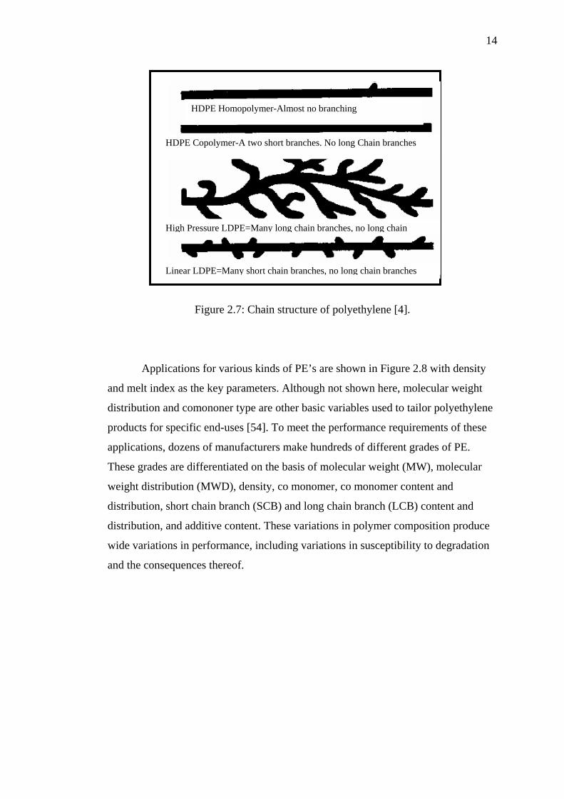
Figure 2.7: Chain structure of polyethylene [4].
Applications for various kinds of PE’s are shown in Figure 2.8 with density
and melt index as the key parameters. Although not shown here, molecular weight
distribution and comononer type are other basic variables used to tailor polyethylene
products for specific end-uses [54]. To meet the performance requirements of these
applications, dozens of manufacturers make hundreds of different grades of PE.
These grades are differentiated on the basis of molecular weight (MW), molecular
weight distribution (MWD), density, co monomer, co monomer content and
distribution, short chain branch (SCB) and long chain branch (LCB) content and
distribution, and additive content. These variations in polymer composition produce
wide variations in performance, including variations in susceptibility to degradation
and the consequences thereof.
HDPE Copolymer-A two short branches. No long Chain branches
HDPE Homopolymer-Almost no branching
High Pressure LDPE=Many long chain branches, no long chain
Linear LDPE=Many short chain branches, no long chain branches

15
Figure 2.8: Polyethylene product range [53]
2.5.3 Effect of Changes In Molecular Weight
Every polyethylene consists of a mixture of large and small chains consisting
of molecules of high and low molecular weights. Molecular weight exerts a great
influence on the process ability and the final physical and mechanical properties of
the polymer. Thermoplastics for piping systems are of high molecular weight (over
100,000) but not so high as to hamper shaping during manufacture or subsequent
operations such as heat fusion [48].
Molecular weight is controlled during the polymerization process. The
amount of length variation is usually determined by catalyst, conditions of
polymerization, and type of process used. During the production of polyethylene, not
all molecules grow to the same length. Since the polymer contains molecules of
different lengths, the molecular weight is usually expressed as an average value.
There are various ways to express average molecular weight, but the most common
is the number average (Mn) and weight average (Mw). The definitions of these terms
are as follows [49]:

16
Mn = Total weight of all molecules ÷ Total number of molecules
Mw = (Total weight of each size)*(respective weights) ÷Total weight of all
molecules.
Molecular weight is the main factor that determines the durability, long-term
strength, toughness, ductility and fatigue (endurance improve as the molecular
weight increases). The current grades of highly durable materials result from the high
molecular weight of the polymer. Melt flow rate is a rough guide to the molecular
weight and processability of the polymer. This number is inversely related to
molecular weight. Resins that have a low molecular weight flow through the orifice
easily and are said to have a high melt flow rate. Longer chain length resins resist
flow and have a low melt flow rate.
In other words, as average molecular weight increases melt index decreases,
and vice versa. Generally, polyethylenes most suitable for blow moulding
applications should have a melt index in the range of 0.3g/10 min. to 1.0 g/10 min.
2.5.4 Effect of Molecular Weight Distribution on Properties
The distribution of different sized molecules in a polyethylene polymer
typically follows the bell shaped normal distribution curve described by Gaussian
probability theory. As with other populations, the bell shaped curve can reflect
distributions ranging from narrow to broad. A polymer with a narrow molecular
weight distribution (MWD) contains molecules that are nearly the same in molecular
weight. It will crystallize at a faster, more uniform rate. This results in a part that will
have less warpage. A polymer that contains a broader range of chain lengths, from
short to long is said to have a broad MWD. Resins with this type of distribution have
good environmental stress crack resistance (ESCR), good impact resistance, and
good processability [48-50, 59].

17
Polymers can also have a bimodal shaped distribution curve which, as the
name suggests, seem to depict a blend of two different polymer populations, each
with its particular average and distribution. Resins having a bimodal MWD contain
both very short and very long polyethylene molecules, giving the resin excellent
physical properties while maintaining good processability. Figure 2.9 shows the
difference in these various distributions.
Figure 2.9: Schematic representation of molecular weight distribution.
MWD is very dependent upon the type of process used to manufacture the
particular polyethylene resin. For polymers of the same density and average
molecular weight, their melt flow rates are relatively independent of MWD.
Therefore, resins that have the same density and MI can have very different
molecular weight distributions [54].
Low Molecular Weight High

18
2.5.5 Effect of Density and Molecular Weight on Polyethylene Properties
Table 2.2 shows density and molecular weight affect essential properties of
polyethylene. There are some properties, which are definitely not influenced by
either of these basic molecular factors, but depend upon other peculiar traits of the
molecular structure, such as molecular weight distribution or configuration. There
are possibly others for which such influence may be proved at some later date. The
end use will determine which properties are most essential and which polyethylene
resin is best suited for a particular end use.
Melt index, although customarily used for classifying polyethylene resins, is
not always a reliable guide with regard to processability and specific resin and end
product properties. Sometimes there is little relationship between melt index and the
suitability of a polyethylene for a specific application. Melt index must be used in
conjunction with other yardsticks to describe the flow and mechanical properties of a
resin.

19
Table 2.2: Effect of changes in density and melt index on polyethylene properties.
[55 and 56]
Basic Molecular Properties Physical Properties
If density increases
(Note 1)
If melt index increases
(Note 2)
Melt viscosity - Lower
Vicat softening temperature Much higher Lower
Surface hardness (abrasion
resistance)
Higher Slightly lower
Tensile strength:
Yield Much higher Slightly lower
Break Slightly lower Lower
Elongation Lower
Resistance to creep Higher Slightly lower
Flexural stiffness Much higher Slightly lower
Flexibility Lower -
Resistance to brittleness at low
temperatures Lower
Resistance to environmental
stress cracking Lower
Barrier Properties:
MVT rate Lower -
Gas and liquid transmission Much lower -
Grease resistance Much higher Slightly lower
Substrate adhesion (Note 3) Slightly lower Slightly higher
Shrinkage Higher Lower
Warpage Slightly higher Lower
Electrical properties Slightly higher No effect
Notes:
1. For density (or crystallinity) increase within the range 0.915 to 0.965.
2. For melt index increase or decrease in average molecular weight.
3. Especially, physical adherence to porous substrates.

20
2.5.6 Compromise between Stress Cracking Resistance and Rigidity
The relationship between stress cracking resistance and rigidity are shown in
Table 2.3 and Figure 2.10 [49].
Table 2.3: Parameters impacting on the properties [49]
Influence of the increase
of the following parameter
on
:
Rigidity Creep
resistance
Stress
Cracking
Resistance
Density Higher Higher Lower
Proportion of Co
monomer
Lower Lower Higher
Structure of
Polyethylene
Melt Index - Lower Lower
Injection
Injection Speed - - Higher
Temperature on release of
mould
Higher Higher Lower
Compaction Higher Higher Higher
Extrusion Blow Moulding
Temperature on release of
mould
Higher Higher Lower
Consistent Thickness Higher Higher Higher
Processing
Conditions
Radius of angle Higher - Higher

21
Figure 2.10: Evolution of stress cracking resistance and rigidity relative to
density [57, 58].
2.5.7 Environmental Stress Crack Resistance Properties
Chemical resistance increases with density, environmental stress crack
resistance (ESCR) worsens as density rises [59].As shown in Figure 2.11, the
molecular arrangement of polyethylene is a monotonous progression of connected
carbon atoms, with hydrogen’s filling in the vacant bonds. This is what makes PE so
chemically inert and allows the chains to fold neatly into crystals. Amorphous PE
consists of segments of molecules that do not fit into the crystal structure namely,
chain segments that are rejected from lamellae at branch points in the chains. Thus,
more branching results in more amorphous and less crystalline PE i.e. lower density.
Long branches, typical of high-pressure polyethylene, can be about the length as the
main chain segments, whereas short branches, found in linear PE, contain one to six
carbon atoms, depending on which co monomer is used. For example, when butane

22
is the co monomer, the short chain branches will be ethyl groups, containing two
carbon atoms. If butene-1 or hexene-1 is introduced together with the ethylene, these
molecules will become incorporated into the growing polymer chain as shown in
Figure 2.12.
Figure 2.11: Polyethylene-The Molecule
Figure 2.12: Part of a linear polymer chain, showing the side branch structure when
butane (A) or hexane (B) or octane (C) is incorporated
The ethyl (C2) and butyl (C4) side chains interfere with the chain folding
crystallization process and, as the number of side chains increases, the material
exhibits a lower density. Because of its size, the butyl side chain disrupts the
crystallization process more effectively than the ethyl side chain. Partly as a result of
the effect on the crystallization process, hexane copolymers exhibit better stress
crack/stiffness properties than the corresponding butane copolymers. This stress
crack/stiffness relationship is very noticeable in thin-walled containers, for example
milk bottles.

23
Figure 2.13: Stacked lamellar morphology of melt-crystallized polyethylene [13].
Referring to the close-up in Figure 2.13, the number of “D: Loose Tie
Chains” that form chemical bonds between crystal lamellae is the crucial factor in
determining a resin’s ESCR. In high pressure LDPE, a very few long branches cause
most of the density reduction. Long branches are likely to become re-entry chains (A
& B :). A linear resin of the same density has many more short branches that are
rejected by the crystals into the amorphous regions and that can became tie chains
joining the lamellae. Consequently, the ESCR of an LLDPE resin is orders of
magnitude higher than that for an equivalent HD and LDPE resin.
Figure 2.14: Molecular effect on ESCR

24
The very strong effect of density on ESCR for linear PE is shown in Figure
2.14, using data from the constant strain bent strip test. Since the polymer relaxes
over time by creep and test samples do not fail, the results at low densities are just
extrapolations. As density rises, the constant strain test method is increasingly
severe, because the stress level is higher at equal strain for a stiffer material.
Nevertheless, a large change in ESCR resulting from a small change in density is a
real phenomenon.
The effects on ESCR of several other molecular PE features are represented
in Figure 2.14 by the vertical arrows. (Please note that there is no significance to the
placement of these arrows along the density). Co-monomer type, melt flow ratio and
melt index, can also contribute a factor of ten or more to ESCR, working through the
same tie chains already discussed, lower melt index means longer average molecules,
which are more likely to join two crystal layers. Likewise, higher MFR is good, if the
branching of molecular weight distribution is on the high molecular weight end.
Again, this change provides more long molecules to act as tie chains. Finally, going
from butane as the co monomer to higher alpha olefins (HAO), also improves ESCR,
through the mechanism for increasing ESCR by increasing the length of the short
branches is not completely understood at present.
Figure 2.15: Rapid change of elongation with density

25
Another illustration of tie chain effects is seen in Figure 2.15, the rapid drop
in elongation reflects a loss of bonding between lamellae as the tie-chain
concentration falls below some critical value. Within a family of resins, the density at
which this drop occurs depends upon the same molecular PE features that affect
ESCR, i.e. co monomer and molecular weight distribution details. The key points are
that lower density and linearity are dominant factors for excellent ESCR properties
but that other aspects of molecular structure are also very important.
2.6 Overview of Crosslinked Polyethylene Technologies
2.6.1 Introduction
Polyethylene molecules do not ordinarily link to one another within the
polymeric matrix. The strength, toughness, flexibility or stiffness of various grades
of polyethylene depends on degrees of molecular entanglement [60]. However, there
is significant interest in how chemical joining of individual polyethylene molecules
alters performance of the original base resin. This chemical joining, known as
crosslinking, has been used extensively in wire and cable and pipes extrusion
applications. Crosslinking facilitates processability while further improving long-
term performance. The technology has also become more prevalent in rotational
moulding and blow moulding. Interest in crosslinking polyethylene has raised
significant confusion about its nature and benefits. In literature survey, BP Solvay
[61] provides the following overview of crosslinkable polyethylene technology.

26
2.6.2 Crosslinked Polyethylene
XLPE and PEX are the term for crosslinked polyethylene. Three principal
technologies may be used to make crosslinked polyethylene products. All three
methods link single strands of PE through radical reactions between the molecules to
form a dense network. Generally, any of the three methods may be used to produce
PEX pipe in accordance with the applicable ASTM standards, which require 65-80%
degree of crosslinking [38]. The number of links between molecules determines
cross-link density. It directly affects the material’s physical properties. The degree
and nature of crosslinking achieved by any of the three methods may be quantified
by the xylene extraction process set forth in ASTM D2765 [62].
2.6.3 Crosslinking Improve Polyethylene Properties
The primary reason to crosslink polyethylene is to raise the thermal stability
of the material under load. For example, pipes manufactured from high-density
polyethylene (HDPE) can be assigned a pipe rating based on hydrostatic stress data
obtained at different temperatures [63]. In general, continuous temperature ratings
exceeding 60°C are rare. Crosslinking of polyethylene change the polymer from
thermoplastics to thermosetting material. Once the crosslinking is completed, the
service temperature can be raised to at least 100 °C and sometimes as high as 120 °C,
depending on starting density, degree and type of crosslinking. ESCR also increases
dramatically, as evidenced by improved resistance to slow crack growth. Tensile
strength tends to remain the same or increase slightly, but there is a considerable
drop in elongation at break. Crosslinking and subsequent chain entanglement make
the PE much stiffer. At the same time, crosslinked polyethylene retains most of the
desirable properties of normal polyethylene [64]. For example, the advantages of its
lightweight, flexibility, good chemical resistance and non-toxicity. Several of these
physical properties are summarized in Table 2.4.

27
Table 2.4: Changes in properties of polyethylene after crosslinking
Property Change from HDPE to XLPE
Melt index Decrease
Density No changes or decrease
Molecular weight Significantly increased
Tensile strength No changes or increases slightly
Elongation at break Decreases
Impact resistance Significantly improved
Abrasion resistance Greatly improved
Stress-crack resistance Greatly improved
Elastic properties Greatly improved
Environmental Stress Crack Resistance
(ESCR)
Increase
Resistance to slow crack growth Increase; higher temperature
hydrostatic design basic (HDB)
Temperature resistance Greatly improved (long term
working temperature increased to
95°C)
Chemical resistance Significant increase
2.7 Methods of Crosslinking Polyethylene
The idea of crosslinking polyethylene to achieve better properties is not new.
The first commercially available crosslinking method is similar to rubber
vulcanization. This method uses peroxide based chemical to create a direct carbon-
to-carbon link within the polyethylene structure. Commercially available crosslinked
polyethylene compound produced using this method has been used for more than 20
years. The various common crosslinking methods of polyethylene are summarized
in Figure 2.16[65].There are two broad categories of crosslinking methods for

28
polyethylene. One of which employs physical crosslinking while the other uses
chemical agents to achieve crosslinking.
Figure 2.16: Polyethylene crosslinking technologies [66].
Physical
Silane copolymers
(Reactor)
Crosslinking of Polyethylene
Chemical
Radiation Silane Peroxide AZO
Sioplas Monosil Siloxan
Mallerfer Process
Engle Pont à Mousson Doaplast
Siloxan Process

29
2.7.1 Physical Crosslinking (Radiation Method)
Radiation crosslinking is carried out on products produced by conventional
extruders. The crosslinking step is affected by high-energy radiation, for example
electron beams or gamma rays. The crosslinking technique is comparable with that of
peroxide crosslinking but the free radicals are not produced by peroxides but by the
radiation. This method uses high-energy radiation to achieve crosslinking. The PE is
simply subjected to a dose of high-energy electrons to crosslink the material (Figure
2.17). Both electron beam and gamma ray can be used for crosslinking. Products of
polyethylene are initially, formed by using normal thermoplastic production methods
(for example, extrusion). After which, the product is subjected to radiation. The
hydrogen atoms originally present in the molecules are “knocked off” from the
carbon atom by the high-energy radiation, leaving behind a free radical polymeric
chain. This free radical is unstable and will seek for another free radical carbon
adjacent to it to form a stable bond. As irradiation progress, bonds are formed.
Hence, creating a crosslinked structure.
2RH 2[R-H]* 2R* H2
2R* R-R
Figure 2.17: Beta irradiation crosslinking technique
This method of crosslinking can occur simply at room temperature and
crosslinking takes place in the solid state [66]. However, this process has its
drawback. The shortcoming is that it may have tendency towards uneven
crosslinking. In many applications, the radiation crosslinking is only applied for
maximum thickness of 2.5 mm. Therefore; it is restricted to products of smaller
sizes. Another disadvantage of this method lies in potential nonuniformities in the
crosslink density as compared to the other two crosslinking methods. Furthermore,
the requirement of initial investment and running cost are significantly higher
Beta Irradiation
PE Molecular Transition State(1)
(2 )

30
compared to other crosslinking methods [67, 68]. Elevated costs of installation and
operation, plus the somewhat elaborate precautions needed to protect personnel from
radiation together with government permits required, detract from the popularity of
irradiation.
2.7.2 Chemical Crosslinking
The other broad category of crosslinking method employs chemicals to
achieve the bonding. Some methods form a direct carbon-carbon bond while others
use a chemical bridge to connect the polyethylene molecules. The three main
methods of chemical crosslinking are the peroxide method, AZO method and silane
methods. The major chemical processes are described as follows:
2.7.2.1.1 AZO Method
This method of crosslinking use AZO compound (molecules with
groupings of (- N = N-) to perform the crosslinking. This is a two-stage method.
First of all, normal thermoplastic processes form the product. The temperature of the
process must not exceed the critical temperature in which AZO compound may
become reactive. Thereafter, the product is being passed through a high temperature
bath, which raises the temperature to allow the AZO bond to be initiated and thus,
creating crosslinking.

31
2.7.2.2 Peroxide Method
Peroxide crosslinking uses peroxide agents [4, 69] (with a -O-O- structure) to
initiate the reaction of hydrogen abstraction. In this system, the polymer is
crosslinked in the presence of peroxides at high temperature. Peroxides are heat-
activated chemicals that generate free radicals (initiation reaction). Radicals are
carbon-based entities, which possess a free electron. The radical abstracts a hydrogen
atom from one of the carbon atoms in the PE chain, leaving localized PE radical or
reactive species.
This reactive species can then form a crosslinking bond with PE radical or
abstract hydrogen from another PE strand creating another free radical. Two adjacent
carbon atoms of such condition will form a carbon- carbon bond to achieve stability,
thus, forming a cross-link. These chain termination and propagation reactions appear
in a simplified form in Figure 2.18 [4, 70-72].
This process will propagate until the peroxide agent is exhausted. This
method of crosslinking produces methane gas as by-product. As such, high pressure
has to be applied to the product while undergoing crosslinking. Otherwise, escaping
methane gas will form pores or pin holes in the product. Such pores or pinholes will
cause weakness in the final product.
Rο-O-ORο 2Rο-Oο
Rο-Oο + R-H Rο-OH + Rο
Rο+Rο R-R
R-H Polyethylene molecule
Figure 2.18: Peroxide crosslinking technique
Heat

32
In the extrusion processing, the decomposition temperature of the peroxide
must not be exceeded at any point. Such step therefore requires extremely precise
temperature and process control since otherwise pre-crosslinking in the extruder can
result in deposits on the screw and stoppage of the machine. In addition, crosslinking
with this method occurs in the melt-phase and as a result a considerable drop in
density of the modified product is evidence.
Peroxide is either adsorbed onto PE flakes or pellets. The mixture is usually
processed in a chamber containing a reciprocating piston to quickly melt the PE -
Engel process [70]. The molten PE is shaped into a pipe with conventional dies.
Further heating allows the peroxide to complete the crosslinking process with a
conventional extruder; the heat profile must be carefully controlled to prevent
premature crosslinking in the barrel, which would generate excessive pressures. In
this situation, a short L/D and specially designed screw are highly desirable. Only the
peroxide technique permits crosslinking in the melt phase and, as a result, a
considerable drop in density of the solidified product can be seen. Temperature
control of the overall process is vital. Peroxide suppliers can provide prospective
users time/temperature charts to help set up process conditions.
The common variations of peroxide crosslinking are Engel method (the first
commercially available crosslinking method), Pont-a Mousson method (PAM) and
Daoplast method.This method has the advantage of potentially producing items that
have higher cure levels than the other two crosslinking processes. Gel levels of 90%
are achievable using a peroxide cure, but care must be taken because that can be too
high for some applications. One major disadvantage with this method is a limitation
on the number of additives (such as antioxidants) employed in the compound, as they
can interfere with the reaction. In addition,stabilization systems can become more
complex. Some other disadvantages of this method can include high capital
investment for the equipment, the energy-intensive nature of the process, high scrap
rates, low outputs, and limitations on part thickness[4, 68].

33
2.7.2.3 Silane Method
Silane crosslinking uses a siloxane bridge to link polyethylene molecules.
There are a few variations to achieve silane crosslinking. The chemistry of this
method is illustrated in Figure 2.19 [4, 68, and 72].
Rο+ CH2 – CH2 –R + 2Rο -Oο + CH2 = CH-Si(OMe)3
Grafting Reaction
PE Material Peroxide Radical VTMO Rο – CH – CH2 - CH2 – Si(OMe)3 H20
Catalyst
CH2 - Rο
(1)
R – CH – (CH2)3 – Si(OMe)3OH + MeOH CH2 - Rο
(2)
2R – CH - (CH2)2 - Si(OMe)3OH Heat H2O OMe OMe RCH- (CH2)2 – Si – O – Si - (CH2)2 – CH + H2O CH2- Rο OMe OMe CH2- Rο
(3)
Figure 2.19: Silane crosslinking technique
The first step is the grafting of the chemical silane onto the polymeric chain
to form vinyl silane copolymer. Peroxide agent again will initiate the reaction at
elevated temperature and form free radicals. Free radicals of peroxide agent will
abstract hydrogen from the polyethylene molecules, thus creating unstable carbon
(step 1 of Figure 2.19). After which, silane is grafted onto the carbon atom to form a
copolymer and the remaining free radical on the copolymer branch will continue to
abstract a hydrogen atom from other polyethylene molecule to become stable (step 2
of Figure 2.19).

34
This abstraction of hydrogen to form a stable copolymer further propagates
the action of the silane grafting. At this stage, the copolymer still remains as
thermoplastic that can be processed as any thermoplastic could. The resulting of
copolymer is put into the converters to form the finished product. For example, pipes
or cables.
The next step requires the finished product to be cured (i.e. converting the
grafted copolymer into a crosslinked network) using moisture as an active reagent.
The curing involves hydrolysis and condensation reaction, which results in a
molecule of water being generated, which in turn initiates another curing reaction
(step 3 of Figure 2.19). This reaction continues until all the grafted copolymer is
converted to cross link chains.
2.7.2.3.1 Sioplast Method
Dow Chemicals originally developed this method in 1973. In the Sioplast
process [73-74], a PE resin is melted and silane is added to the melted PE along with
a peroxide initiator. Crosslinking sites are thereby formed on PE polymer chains and
crosslinking begins to occur. The grafted resin is palletized and stored for later use in
foil-lined bags. As crosslinking of the grafted resin occurs in the presence of
moisture, it is important that the grafted resin not be exposed to moisture until
substantial crosslinking is desired. However, since this method of crosslinking of PE
is self-perpetuating, the crosslinking reaction producing moisture as a byproduct, it is
not practical to completely prevent crosslinking in the pelletized grafted PE resin and
so it has a shelf life of only approximately 6 to 9 months.
A catalyst masterbatch is prepared for the grafted resin. The catalyst
masterbatch typically includes a quantity of PE, a catalyst, an antioxidant, a
stabilizer, and an internal lubricant. The catalyst masterbatch is typically palletized
for ease of mixing with the grafted resin in a conventional extruder. The grafted resin

35
and catalyst masterbatch are usually combined in a specific ratio, melted and mixed
together, and extruded. When the grafted PE resin and catalyst masterbatch are
mixed together, crosslinking of the PE at the silane graft sites accelerates. The
material exits the extruder and is typically cooled in water.
The process is referred to as "two-step" because two distinct steps are used to
obtain the final crosslinked product. In the first step, the material compounder grafts
silane to the polyethylene. In the second step, the processor mixes the grafted
compound with a catalyst and processes it into a finished product. The process is
straightforward and allows for high output rates with low scrap using conventional
extrusion equipment. The compounder can tailor formulations to fill the processor's
specific requirements. Sioplas practitioners have the option of purchasing the grafted
PE and catalyst masterbatch from a compounding company.
2.7.2.3.2 Monosil Method
This system utilizes a one-step process to perform grafting of silane to the
polymeric chain and subsequently crosslinking the product. This system, developed
by Maillefer and BICC in 1978, requires a specially designed extruder with a high
L/D ratio (about 30) that is more expensive than conventional PE extruders used for
Sioplast process. Meanwhile, the Monosil system [75] is rather limited to small
diameter pipes. This approach needs high initial investment and extensive training to
operate the system. In the Monosil process all the ingredients are fed directly into
special purpose extruder through a hopper. Consequently, great care is needed to
achieve the grafting without excessive crosslinking as the grafting reaction occurs in
the same extruder.
In this monosil one-step process, the grafting takes place during the
fabrication of the product, whether it be wire, pipe, or other profile. The silane,
initiator, polyethylene, catalyst, and antioxidants are all introduced in the same

36
operation and the extruded product begins to crosslink immediately. While this
process seems simple and appears to have economic advantages, the need for special
processing equipment, specialized training and equipment for handling and storage
of the chemicals, and the high degree of specialization needed to manage the
generation of scrap offsets this apparent advantage. Furthermore, this method can
place limits on the inclusion of specialty additives required for particular applications
because they can inhibit the grafting process. Thus, formulation is critical and
requires specialized and experienced personnel.
2.7.2.3.3 General Variation of the Monosil Process and the Sioplas Process
Dow Chemical developed moisture-cured crosslinking in the late sixties. Two
major variants, the Monosil process and the Sioplas process, have emerged. The
Monosil technique introduces vinylsilane into the polyethylene during conventional
extrusion of polyethylene pipe. In the Sioplas technique, however, PE resin is first
compounded with vinylsilane and peroxide. This compound combines with a catalyst
masterbatch, which is then fed into the extruder for conversion into pipe. In both
cases, the objective is to graft a reactive silane molecule to the backbone of the
polyethylene. The pipe then cures in a high-temperature water bath for several hours,
or goes into a steam sauna so the material can be crosslinked. The important
difference between the variants is that the Monosil process is a one-step reaction and
the Sioplas process has two steps. The crosslinking mechanism is different from that
of the peroxide method. Water attacks one of the methoxy (Ome) groups to generate
a silanol. Two silanol groups subsequently form a new chemical bond in a
condensation process that eliminates water. This crosslinking takes place in the solid
state.
A problem associated with both the SioplasTM process and the MonosilTM.
Process methods are the difficulty of adequately combining some or all of the silane,
peroxide catalyst and hydrolysis/condensation catalyst (some or all of which are
liquids) with the base polymer, which is a solid. If the silane is injected as a liquid

37
stream into a conventional extruder and mixed with a polymer, small gels form
throughout the polymer product, apparently because of localized, premature
crosslinking in areas of high additive (silane and catalyst) concentration resulting
from inadequate mixing. When a silane is sprayed into a polymer, additional
apparatus is required, and the silane must be sprayed uniformly. High demands are
placed on the uniformity of mixing at or near the spraying point to equalize
variations in concentration and ensure that the silane is distributed homogeneously.
To complete the crosslinking process, the extruded material from either the Sioplas
or Monosil process is generally exposed to moisture at an elevated temperature. A
sauna-like environment or hot water immersion will produce the desired level of
crosslinking in a relatively short period of time. When this curing stage is finished,
the PE may be approximately 65-89% crosslinked.
2.7.2.3.4 Siloxan Method
This method is a one-pack system and the product consists of all chemical
specially compounded into one single compound. This eliminates the need of
separating the catalyst from the grafted copolymer. This method of crosslinking is
much easier to use compared to other silane crosslinking methods because there is no
need to mix the components prior to production (like the Sioplast method). Silane
crosslinkable polyethylene is a compound (product) produced using this method.
Simple comparison of several crosslinking is shown in Table 2.5.

38
Table 2.5: Comparison of several crosslinking methods [76].
Crosslinking
Process
Silane
Siloxane
Peroxide
Enger
Radiation
E-beam
Process
Flexibility
Very Good Small Very Good
Operation Easy
Difficult Difficult
Operation
Efficiency
High Low Medium
Extruder Standard
Special Standard
Output High as For PE
Low High as For PE
Cost Of Post
Treatment
Low - High
Initial
Investment
Low High High
Minimum required
strength rating
High
Medium High
Diameter No limit,
Thickness limited
By speed of
crosslinking
Difficult to
achieve big
diameter because
of output
Limited by
penetration depth
of electrons

39
2.7.2.3.5 Silane Grafting Reaction Mechanism
Figure 2.20 shows a schematic of the reaction mechanism of VTMO grafting
to a polymer matrix via free-radical initiation [7,145]. A three-step reaction
mechanism is required to attain the desired grafted product. [149] First, the DCP
must dissociate to form a peroxide radical under the extrusion conditions with melt
temperature 170±5°C [148]. Peroxide radical then reacts with a polymer chain,
undergoing a radical transfer to create an alcohol and a polymer radical. At this
point, the polymer radical can react with the VTMO. This reaction, followed by a
radical transfer, results in the formation of the desired silane graft. However, other
reactions, including chain scission and direct crosslinking, are also possible
[146,147,150]. The polymer radical can undergo chain scission, creating an
unsaturated hydrocarbon chain, which can go on to form a chain graft with another
polymer radical. Also, the polymer radical can undergo direct crosslinking with
another polymer radical, terminating the reaction [150]. VTMO grafting is the
desired reaction during extrusion because it allows the HDPE polymer to retain
essentially the same processing characteristics while functionalizing it for post-
extrusion modification. If direct hydrocarbon crosslinking occurs in the extruder, the
molecular structure of the polymer matrix will be chemically fixed. This will greatly
reduce the process ability of the post-extruded polymer and will limit the formation
of the desired silane crosslinks.
Results for post-extruded samples prior to silane crosslinking revealed that DCP,
in the absence of VTMO, initiated some direct hydrocarbon crosslinking between
polymer chains. VTMO alone, however, produced no grafting to the polymer and
acted solely as a plasticizer or lubricants. The presence of both DCP and VTMO
resulted in a competition between silane grafting and direct hydrocarbon
crosslinking. However, sufficient silane grafting was produced and dependent on the
reaction time or rate, temperature as is evident from DSC, gel content a shown in the
FTIR measurements results.

40
The kinetics of crosslinking appeared to increase with increasing temperature,
possibly because of the increase in the oxygen radical diffusion in the matrix with
increasing temperature and the increase in the rate of oxygen radical formation.
However, both the crosslinking kinetics and the extent of the elastic modulus
increase (low MFI) relative to the initial value were functions of the initial DCP
concentrations. An optimum DCP concentration existed that favored silane-graft
crosslinking over direct hydrocarbon crosslinking.
Step1 Grafting PE + Silane + Peroxide
Step 2 Hydrolysis: catalyst, H2O
Step 3 Condensation: catalyst
Figure 2.20: Schematic of the reaction mechanism for the grafting of VTMO to
HDPE polymer chains in the presence of peroxide and heat during reactive extrusion.

41
2.8 Crosslinking Method Selections.
Available studies show that any of the techniques presented will generate
good crosslinked products, provided the technique is followed correctly with good
quality control. Choice of the technique is usually dictated by the user’s needs and
equipment availability. The peroxide method requires a reciprocating-piston type
extruder or an extruder with suitable modifications. The technique also requires the
user to safely handle peroxides. Variability of crosslinking with this method is
potentially the highest. The degree of crosslinking is directly proportional to
peroxide concentration, antioxidants levels, and process temperature. It is certainly
the most demanding technique. Users choose it because of its one-step processing.
Vinylsilane moisture-cure techniques are less demanding and can be
accomplished on most extrusion equipment. The choice among the variants gives
users the option of simplifying the process even more (a trade-off between raw
materials and number of steps to perform in manufacturing terms). The only
drawback is that a sauna or water bath must be operated consistently to ensure the
required degree of crosslinking.
At this time, in-line beta irradiation equipment remains costly. This may
necessitate that pipe be transported to an off-site facility that specializes in irradiation
technology. Cost for additional shipment and handling must be carefully evaluated,
since the U.S. has only a few specialized facilities. Nevertheless, as the number and
size of these facilities continue to increase, both the processing fee and associated
transportation costs may decline. Beta irradiation also remains the only post-
extrusion crosslinking technique.
Therefore, siloxan one-step process and one pack method has been selected in
this study to produce silane cross-linkable HDPE for extrusion blow moulding.
Through this method, silane crosslinkable olefin excellently imbalances the extrusion

42
processability as well as in cross-linking property, mechanical property and heat
resistant property. This process has been developed to overcome the aforesaid
problem of others cross-linking process or method.
2.9 Chemical Additives Used In Formulation
2.9.1 Crosslinker -Vinyltrimethoxysilane (VTMO)
The purpose of the organic unsaturated vinyltrimethoxysilane is for grafting
onto the base resin to serve as the point which crosslinks the base resin molecules
with each other. Hydrolysable olefinically unsaturated silanes suitable for grafting
onto and crosslinking the polymers according to this invention include
organofunctional silanes of the general formula [77]:
R (CH2. CH2. CH2). M Si (R.1). 3-n X.n
Wherein R represents a monovalent olefinically unsaturated hydrocarbon or
olefinically unsaturated hydrocarbonoxy group which is reactive with the free radical
sites generated in the polymer by the free radical generator. R1 represents an
hydrolysable organic group such as an alkoxy group having 1 to 12 carbon atoms
(e.g. methoxy, ethoxy, butoxy), aralkoxy groups (e.g. phenoxy), aliphatic acyloxy
groups having 1 to 12 carbon atoms (e.g. formyloxy, acetoxy, propionoxy), oxymo or
substituted amino groups (alkyl amino and aryl amino)X represents a monovalent
alkyl, aryl or aralkyl group (e.g. ethyl, methyl, propyl, phenyl, benzyl), m is 0 or 1
and n is 0, 1 or 2.

43
Preferably the unsaturated silanes will contain two or three hydrolysable
organic groups and a vinyl or methacryloxypropyl group as the group reacting with
the free radical sites formed in the polymer by the free radical generator. Some
representative examples of the unsaturated silanes applicable in the crosslinking
process are vinylmethyldimethoxysilane, vinyltriethoxysilane, vinyltrimethoxysilane
[78].
The amount of silane crosslinker used in the practice of this research can vary
widely depending upon the nature of the ethylene polymer, the silane, the processing
conditions, the grafting efficiency, the ultimate application, and similar factors.
Selection of the optimal silane for an application requires consideration of several
factors including [79]; the resin in the formulation, the filler in the formulation. the
target substrate and the cure conditions (room temperature, elevated temperature).
The amount of vinyltrimethoxysilane silane is chosen so as to be near the
minimum amount needed to provide the desired degree of crosslinking. The amount
of the organic unsaturated silane to be used may vary/ added commonly from 0.1-5%
by weight, preferably 0.7-3% by weight, based on the total weight of polymers [77].
The concentration of vinyltrimethyloxysilane relating to 100 parts of base
polymer should be 1.6 - 2.0 phr. When the amount is less than 1.6 parts by weight, a
sufficient grafting does not take place. An amount larger than 2.0 parts by weight
may cause defective moulding and also is economically disadvantageous. Lower
concentration reduces the safety margin with respect to the requirements to hot set
and gel content. A dosage of more than 3 parts does not significantly improve the
crosslinking results [77]. These vinyltrimethyloxysilane is commercially
manufactured by Crompton (silquest A171) [80], Degussa (Dynasylan® VTMO) [81]
and Shin Etsu (KBM 1003) [82].

44
2.9.2 Peroxide - Dicumyl Peroxide (DCP).
Peroxide is to produce free radical sites in the polymer. The reaction
conditions depending on temperature and retention time needed for achieving a
suitable half-life time [83].The free radical generating agent used in this research acts
as an initiator of silane grafting. The general formula is; C18H2202 [84].
The amount of free radical generator necessary in the present invention is not
narrowly critical and can be varied over wide ranges, for example, from 0.01 part to
1.0 part preferably 0.05 to 0.2 part based on the total weight of the extrudate,
depending on the nature of the base polymer, the silane, the presence of stabilizers,
the extrusion conditions [9]. When the amount is less than 0.01 parts by weight, the
silane grafting does not proceed sufficiently. When the amount is larger than 0.5
parts by weight, both the extrusion processability and the surface appearance of
mouldings tend to be poor [84]. Satisfactory mechanical properties can be obtained at
the lowest dosage levels. Higher levels improve the compression set properties. The
highest levels should not be exceeded, or remaining mechanical properties will be
reduced [15].
The grafting conditions can vary, but the melt temperatures are typically
between 160 and 200 °C, preferably between 170 and 180 °C, depending upon the
residence time and the half-life of the initiator [86]. This dicumyl peroxide is
commercially available from different companies with their trade name such as
PERCUMYL D® [84], Luperox® DCSC [87] and Perkadox BC-FF [88].

45
2.9.3 Hydrolysis Condensation Catalyst - Dibutyltin Dilaurate
Hydrolysis or condensation catalysts catalyze the crosslinking of the
extrudate by reaction of the extrudate with water. The catalysts may accelerate either
the hydrolysis reaction of the grafted silyl groups with water to form silanols, or the
condensation of silanols to form Si-0-Si bond or both. These catalysts may be Lewis
acids, such as tin carboxylates, for example: dibutyltin dilaurate, dioctyltin dilaurate,
stannous acetate, stannous octoate, dibutyltin dioctoate, di-octyl tin-bis
(isooctylmaleate), di-octyl-tin-bis (isooctylthioglycolate). The most effective catalyst
for silane crosslinking is dibutyltincarboxylates such as dibutyl tin dilaurate
(DBTDL) [89].
The proportion of silanol condensation catalyst used is not narrowly critical,
illustratively ranging from 0.01 to 0.2 parts, preferably 0.015 to 0.1 part based on the
total weight of the polymers [91]. The standard concentration in the Siloxan Process
is 0.08 phr (the lower limit is about 0.025 phr). Lower concentration than 0.025 phr
lead to reductions in degree of crosslinking and require longer periods of exposure to
moisture, while concentration exceeding 0.08 phr causes premature to moisture
reactions during extrusion (increased melt viscosity) and may lead to processing
problems. The formation of a spatial network consisting of polyethylene chains tied
together by Si-O-Si linkages occurs in the second phase of the Siloxan process with
the aid of moisture. The crosslinking catalyst plays an important role in this phase
with respect to the degree of crosslinking that may be achieved [90].

46
2.9.4 Phenolic Antioxidants- Pentaerythritol Tetrakis (3-(3, 5-di-tert- butyl-4-
hydroxyphenyl) Propionate [92]
Generally, most polymer materials contain some stabilizers such as
antioxidant to prevent oxidation degradation. For the crosslinking of polymers, the
antioxidants are known to retard the reaction, so the selection of a suitable
antioxidant has been empirical. This is often very complex, especially when a
mixture of several antioxidants is used. The various classes of stabilizers that are
used in crosslinkable polyethylene display a highly differing potential of interference
in silane crosslinking. Phenolic stabilizers show strong interference [93]. Its
concentration in crosslinkable polyethylene depends on the end use of the parts and
on the protection requirement, the usual concentration ranges between 0.005-0.2 phr.
[94].
2.10 Influence of Blend Components on the Crosslinking Reaction
2.10.1 Fillers
Insufficient of crosslinking reaction in presence of a number of acidic fillers,
in particular silicic acids, due to the catalyzed ionic decomposition of the peroxides.
The adsorption of peroxides on the surface of certain fillers such as talc and silicates
also leads to the possibility of inadequate cross-linking. In such cases, this can be

47
remedied by increasing the peroxide quantity and/or by the addition of co agents
[78,126].
2.10.2 Plasticizers, Extender Oils and Wax
With the exception of plasticized PVC, cross-linked thermoplastics do not
generally contain plasticizers or extender oils. In rubbers and a number of special
applications in which these auxiliaries are used, these additives reduce the cross-
linking effect to a greater or lesser extent. In this respect, aromatic oils have the most
adverse effect whereas a phathenic and paraffin oils exhibit only a slight effect [78].
Mtshali and colleague [96] reported that the wax and crosslink LDPE were
not mutually miscible at higher wax concentrations in the crystalline phase, as well
as in the melt. The thermal stability of the blends decreased with an increase in wax
content. Krupa and Luyt [97] also reported that the thermal stability of crosslinked
blends in synthetic air atmosphere is much lower than in nitrogen atmosphere, and
they decrease with an increase of wax portion. This is a logical consequence of the
lower thermal stability of the wax.
2.10.3 Antioxidants
It is very important to investigate the influence of such additives to control
both the crosslinking reaction and the resultant physical properties such as thermal
resistance, mechanical strength, and dielectric loss tangent of crosslinked
polyethylene (XLPE). Most antioxidants reduce the effectiveness of peroxides.
According to Mallégol and coworker’s report [98], a normal level of poly-2, 2.4-
trimethyl-1, 2-di-hydroquinoline diminishes the efficiency of peroxides by
approximately 10% and causes a slight discoloration. In the presence of antioxidants
such as alkyl substituted phenylenediamines and sterically hindered phenols, cross-

48
linking is inhibited to a greater or lesser extent, depending on the structure of the
peroxide and the antioxidants. Frequently applied antioxidants for crosslinked
polyethylene are mentioned by Gugumus in plastic additives handbook [78].
Chariesby [99] reported that the effect of these and other antioxidants may
not only reduce the oxygen effect, it may also reduce the degree of crosslinking.
Hence, those higher doses of peroxide are needed for the same degree of
crosslinking. This could be by the transfer of energy to the antioxidant, or the
scavenging of polymer radicals, which might otherwise result in a crosslinked
species.
Takanori Tamazaki and Tadao Seguchi [19,100-103] studied the effect of an
antioxidant on the reaction mechanisms of chemical crosslinking of polyethylene
with dicumyl peroxide at high temperatures by using electron spin resonance (ESR).
The effects of antioxidants when added to the PE crosslinking reaction determine
free radical behavior. The alkyl radical formation in PE molecules was suppressed by
some antioxidants, where the decomposition products of DCP react with the
antioxidant. For sulfur and phosphorous type antioxidants, changes of radical species
and their contents during the PE crosslinking reaction were observed. It was
confirmed that these antioxidants reacted preferentially with radicals yielded by
decomposed DCP, restraining the crosslinking of PE by the increased antioxidant
content. The compound of DCP and antioxidant decomposed to form 2-phenyl
isopropyl radicals, which may initiate PE crosslinking. The ESR technique used in
this study can be applied for the selection of an antioxidant in the thermochemical
crosslinking process capable of maintaining suitable conditions to optimize the
properties of crosslinked polymers.

49
CHAPTER 3
METHODOLOGY
3.1 Materials
3.1.1 High Density Polyethylene
The blow moulding grades of HDPE used in this study were : Titanex® HB
3771 with melt index 0.35 g/10 min, density of 0.954 g/cm3 , 1-hexane comonomer -
Unipol Technology and HDPE ,Titanzex® HB6200 with melt index 0.35 g/10 min,
density of 0.956 g/cm3, hexene comonomer -Mitsui Technology. Both HDPE grades
were supplied by Titan Polyethylene Malaysia Sdn Bhd. Ethilinas HD5403AA with
0.25 g/10 min, density of 0.954 g/cm3, hexene comonomer –BP gas phase technology
was also used in this study.
3.1.2 Additives
The additives that were used in this research are shown in Table 3.1.

50
Table 3.1: Materials and additives specifications.
Materials Name Trade Name
and Grade
Description Manufacturer
Organofunctional Silanes Dynasylan®
VTMO
Vinyltrimethoxysila
ne
Degussa-Huls
AG
Organofunctional Silanes Dynasylan®
VTEO
Vinyltriethoxysilan
e
Degussa-Huls
AG
Dibutyltin Dilaurate
(DBTL)
TEGOKAT®
218
Hydrolysis/
Condensation
Catalyst
TH.Golds
Chmidt AG
Dicumyl Peroxide PERCUMYL
D
Crosslinking
Peroxide
PT.Nof Mas
Chemical
Industries
2,5-dimethyl-2, 5-di (tert-
butyl peroxy)-hexane
Luperox 101 Crosslinking
Peroxide
Atofina
Chemical Inc
2,5-dimethyl-2-hydroxy-5-
tert-butylperoxy-3-hexyne
Luperox 130 Crosslinking
Peroxide
Atofina
Chemical Inc
Di-Tert-butyl peroxide Triganox B Crosslinking
Peroxide
Azo Nobel
Polymer
Chemical Inc
Pentaerythritol Tetrakis(3-
(3,5-di-tert- butyl-4-
hydroxyphenyl)
Propionate.
Irganox®
1010
Phenolic
Antioxidant
Ciba Specialty
Chemical
(Tris-phenoles)
1,3,5-Trimethyl-2,4,6-tris
(3,5-di-t-butyl-4-
hydroxybenzyl) benzene
Irganox 1330 Phenolic
Antioxidant
Ciba Specialty
Chemical
Thiodiethylene bis[3-(3,5-
di-tert-butyl-4-
hydroxyphenyl)propionate]
(Dual functionality).
Irganox 1035 Phenolic
Antioxidant
Ciba Specialty
Chemical

51
3.2 Chemical and Blends Formulations
The formulation was based upon typical commercial crosslinkable compound
with some modification. The formulation used generally consists of HDPE,
organosilanes, initiator and catalyst .The ingredients were used for blending and are
called crosslinkable formulation. To determine the composition range that required,
the content and concentration of the chemical additives and modifier were varied
accordingly with respect to the blend processability and degree of crosslinking.
After obtaining the chemicals suitable for the crosslinkable formulation the
approximately range or optimum amount of these chemicals were determined so that
the formulations are processable on the blow moulding machine.
3.2.1 Selection of HDPE
There types of commercial HDPE were tested for its ability to undergo
crosslinking process via siloxan process. Titanex HB 3711, Titannex HB 6200 and
Etilinas HD 5403AA of a blow-moulding grade were obtained and its ability verified
by gel content and hot set tests.
3.2.2 Selection of Organosilane
Two types of organosilane, that Vinyltrimethoxysilane (VTMO) and
Vinyltriethoxysilane (VTEO) were tested for its ability to act as a crosslinking agent.
The evaluation is via gel content test and melt flow rate .The effect of organosilanes
concentration was also examined. The followings compositions were used for the
blends preparation: DCP-0.2 phr DBTL 0.01 phr and organosilane 1.0 to 3.0 phr. A
single screw extruder was used, with screw speed of 17 rpm and melt temperature of
175°C, for the sample preparation.

52
3.2.3 Selection of Radical Initiator
Four type of radical initiator were tested. That Dicumyl Peroxide , 2,5-
dimethyl-2, 5-di (tert-butyl peroxy)-hexane, 2,5-dimethyl-2-hydroxy-5-tert-
butylperoxy-3-hexyne and Di-Tert-butyl peroxide were tested for their ability to act
as a crosslinking agent, This is verified via gel content test and melt flow rate .The
effect of organo silanes concentration was also examined. The followings
compositions were used for the blends preparation: DCP-0.2 phr, DBTL 0.01 phr and
organosilane 1.0 to 3.0 phr.
3.2.4 Selection of Catalyst
Suitable materials for use as the silanol condensation catalyst of this
invention include organo-metallic compounds such as dibutyltin dilaurate, stannous
acetate, dibutyltin diacentate, dibutyltin dioctoate, lead naphthenate, zinc caprylate,
cobalt naphthenate, tetrabutyl titanate, tetranonyl titanate, lead stearate, zinc stearate,
cadmium stearate, barium stearate, and calcium stearate. The most preferred catalysts
are the organic tin compounds for example, dibutyltin dilaurate [89]. The aforesaid
catalyst should be present in a quantity within the range of 0.05 to 0.5 parts by
weight per 100 parts by weight of the silane-grafted polyolefin. When a quantity less
than 0.005 parts by weight of the catalyst was employed, a lower degree of
crosslinking was found in the product, whereas a quantity more than 0.5 parts by
weight of the catalyst gave a product having a high surface roughness.
3.2.5 Selection of Antioxidant
The effect of antioxidants were investigated .Three types of primary
antioxidants were examined for its performance in inhibiting oxidation, there are

53
Pentaerythritol Tetrakis (3-(3, 5-di-tert- butyl-4-hydroxyphenyl) Propionate, (Tris-
phenoles) 1, 3, 5-Trimethyl-2, 4, 6-tris (3, 5-di-t-butyl-4-hydroxybenzyl) benzene
and Thiodiethylene bis [3-(3, 5-di-tert-butyl-4-hydroxyphenyl) propionate].
3.3 Mixing Procedures
3.3.1 Preparation of Chemical Liquid Mixture
Vinyltriethoxysilane, dicumyl peroxide and dibutyltin dilaurate (silanol
condensation catalyst) were mixed and stirred for 30 minutes at 40 ºC in a closed, dry
glass flask until a homogeneous liquid mixture was obtained. The mixing parameter
for the above chemical mixture was based on physical observation on degree of
homogeneity and the solubility with respect to various chemical formulations.
3.3.2 Dry Blend of Compounds
The HDPE, in pellet form, was placed in a dry, sealable cylindrical mixer,
filling the mixer to about three-quarters of its capacity .The polymer was injected
with a chemical liquid mixture indicated in formulation as shown in Table 3.2 to
Table 3.9 by using a syringe. The chemical liquid mixture was added and the mixer
was sealed. The PE was dry blended on laboratory scale Fielder mixer (Figure 3.1)
for 2 minutes. At the end of this time, chemical mixture had uniformly coated the
surface of the polyethylene pellets, but the pellets still appeared wet. The time
necessary for complete absorption of the liquid was 2 to 3 hours. After the liquid was
completely absorbed in the PE pellets, the polymer was found to be dry. This pellet
obtained were then stored in a sealed aluminium-laminated bag to isolate from
external moisture.

54
Figure 3.1: Laboratory scale Fielder mixer

55
Table 3.2: Selection of HDPE
Formulations (phr) Ingredient S1 S2 S3
High Density Polyethylene (HB 3771)
100 0 0
High Density Polyethylene (HD 5403AA
0 100 0
High Density Polyethylene (HB 6200)
0 0 100
Vinyltrimethoxysilane (VTMO)
2.0 2.0 2.0
Vinyltriethoxysilane (VTEO)
0 0 0
Dicumyl Peroxide (DCP)
0.2 0.2 0.2
Dibutyltin Dilaurate (DBTL)
0.01 0.01 0.01

56
Table 3.3: Selection Organo silane Formulations (phr) Ingredient S4 S5 S6 S7 S8 S9 S10 S11 S12 S13 S14 S15 S16 S17 S18
High Density Polyethylene (HB 6200)
100 100 100 100 100 100 100 100 100 100 100 100 100 100 100
Vinyltrimethoxysilane (VTMO)
0 1.0 1.2 1.4 1.6 1.8 2.0 3.0 0 0 0 0 0 0 0
Vinyltriethoxysilane (VTEO)
0 0 0 0 0 0 0 0 1.0 1.2 1.4 1.6 1.8 2.0 3.0
Dicumyl Peroxide (DCP)
0.2 0.2 0.2 0.2 0.2 0.2 0.2 0.2 0.2 0.2 0.2 0.2 0.2 0.2 0.2
Dibutyltin Dilaurate (DBTL)
0.01 0.01 0.01 0.01 0.01 0.01 0.01 0.01 0.01 0.01 0.01 0.01 0.01 0.01 0.01

57
Table 3.4: Selection of type of peroxide (I)
Formulations (phr) Ingredient S19 S20 S21 S22 S23 S24 S25 S26 S27 S28 S29
High Density Polyethylene (HB 6200)
100 100 100 100 100 100 100 100 100 100 100
Vinyltrimethoxysilane (VTMO)
2 2 2 2 2 2 2 2 2 2 2
Dicumyl Peroxide (DCP)
0 0.05 0.1 0.15 0.2 0.25 0.3 0.35 0.4 0.45 0.5
2,5-dimethyl-2, 5-di (tert-butyl peroxy)-hexane(L-101)
0 0 0 0 0 0 0 0 0 0 0
2,5-dimethyl-2-hydroxy-5-tert-butylperoxy-3-hexyne (L-130)
0 0 0 0 0 0 0 0 0 0 0
Di-Tert-butyl peroxide(L-Di) 0 0 0 0 0 0 0 0 0 0 0
Dibutyltin Dilaurate (DBTL)
0.01 0.01 0.01 0.01 0.01 0.01 0.01 0.01 0.01 0.01 0.01

58
Table 3.5: Selection of type of peroxide(II)
Formulations (phr) Ingredient S30 S31 S32 S33 S34 S35 S36 S37 S38 S39
High Density Polyethylene (HB 6200)
100 100 100 100 100 100 100 100 100 100
Vinyltrimethoxysilane (VTMO)
2 2 2 2 2 2 2 2 2 2
Dicumyl Peroxide (DCP)
0 0 0 0 0 0 0 0 0 0
2,5-dimethyl-2, 5-di (tert-butyl peroxy)-hexane(L-101)
0.05 0.1 0.15 0.2 0.25 0.3 0.35 0.4 0.45 0.5
2,5-dimethyl-2-hydroxy-5-tert-butylperoxy-3-hexyne (L-130)
0 0 0 0 0 0 0 0 0 0
Di-Tert-butyl peroxide(L-Di) 0 0 0 0 0 0 0 0 0 0
Dibutyltin Dilaurate (DBTL)
0.01 0.01 0.01 0.01 0.01 0.01 0.01 0.01 0.01 0.01

59
Table 3.6: Selection of type of peroxide (III)
Formulations (phr) Ingredient S40 S41 S42 S43 S44 S45 S46 S47 S48 S49 S50
High Density Polyethylene (HB 6200)
100 100 100 100 100 100 100 100 100 100 100
Vinyltrimethoxysilane (VTMO)
2 2 2 2 2 2 2 2 2 2 2
Dicumyl Peroxide (DCP)
0 0 0 0 0 0 0 0 0 0 0
2,5-dimethyl-2, 5-di (tert-butyl peroxy)-hexane(L-101)
0 0 0 0 0 0 0 0 0 0 0
2,5-dimethyl-2-hydroxy-5-tert-butylperoxy-3-hexyne (L-130)
0.05 0.1 0.15 0..2 0.25 0.3 0.35 0.4 0.45 0.50 0
Di-Tert-butyl peroxide(L-Di) 0 0 0 0 0 0 0 0 0 0 0.2
Dibutyltin Dilaurate (DBTL)
0.01 0.01 0.01 0.01 0.01 0.01 0.01 0.01 0.01 0.01 0.01

60
Table 3.7: Selection of Catalyst
Formulations (phr) Ingredient S51 S52 S53 S54
High Density Polyethylene (HB 6200)
100 100 100 100
Vinyltrimethoxysilane (VTMO)
2 2 2 2
Dicumyl Peroxide (DCP)
0.2 0.2 0.2 0.2
Dibutyltin Dilaurate (DBTL)
0 0.005 0.01 0.015

61
Table 3.8: Selection of type of Antioxidant (1)
Formulations (phr) Ingredient S55 S56 S57 S58 S59 S60 S61 S62 S63 S64 S65 S66 S67 S68 S69
High Density Polyethylene (HB 6200)
100 100 100 100 100 100 100 100 100 100 100 100 100 100 100
Vinyltrimethoxysilane (VTMO)
2 2 2 2 2 2 2 2 2 2 2 2 2 2 2
Dicumyl Peroxide (DCP)
0.2 0.2 0.2 0.2 0.2 0.2 0.2 0.2 0.2 0.2 0.2 0.2 0.2 0.2 0.2
Dibutyltin Dilaurate (DBTL)
0.01 0.01 0.01 0.01 0.01 0.01 0.01 0.01 0.01 0.01 0.01 0.01 0.01 0.01 0.01
Pentaerythritol Tetrakis(3-(3,5-di-tert- butyl-4-hydroxyphenyl) Propionate.
0 0.05 0.1 0.15 0.2 0.25 0.3 0.35 0 0 0 0 0 0 0
(Tris-phenoles) 1,3,5-Trimethyl-2,4,6-tris (3,5-di-t-butyl-4-hydroxybenzyl) benzene
0 0 0 0 0 0 0 0 0.05 0.1 0.15 0.2 0.25 0.3 0.35
Thiodiethylene bis[3-(3,5-di-tert-butyl-4-hydroxyphenyl)propionate] (Dual functionality).
0 0 0 0 0 0 0 0 0 0 0 0 0 0 0

62
Table 3.9: Selection of type of Antioxidant (II)
Formulations (phr) Ingredient S70 S71 S72 S73 S74 S75 S76
High Density Polyethylene (HB 6200)
100 100 100 100 100 100 100
Vinyltrimethoxysilane (VTMO)
2 2 2 2 2 2 2
Dicumyl Peroxide (DCP)
0.2 0.2 0.2 0.2 0.2 0.2 0.2
Dibutyltin Dilaurate (DBTL)
0.01 0.01 0.01 0.01 0.01 0.01 0.01
Pentaerythritol Tetrakis(3-(3,5-di-tert- butyl-4-hydroxyphenyl) Propionate.
0 0 0 0 0 0 0
(Tris-phenoles) 1,3,5-Trimethyl-2,4,6-tris (3,5-di-t-butyl-4-hydroxybenzyl) benzene
0 0 0 0 0 0 0
Thiodiethylene bis[3-(3,5-di-tert-butyl-4-hydroxyphenyl)propionate] (Dual functionality).
0.05 0.1 0.15 0.2 0.25 0.3 0.35

63
3.4 Sample Preparation
The blends prepared were extruded through Magic® single screw extrusion
blow moulding machine as illustrated in Figure 3.2.The operating conditions of the
blow-moulding machine are shown in Table 3.10.
Figure 3.2: A schematic diagram of Magic® blow-moulding single screw Extruder

64
Table 3.10: Operating conditions on blow moulding machine.
Magic® Single Screw Extrusion Blow Moulding Machine
Parameter Run Conditions
Extrusion Time (Sec) 19.0-25
Screw Speed (rpm) 20-40
Blowing Time (Sec) 12.0
Barrel Temperature (ºC) Zone 1:130, Zone 2:140, Zone 3:150
Adapter Temperature (ºC) Zone 4:150
Die head Temperature (ºC) Zone 5:160, Zone 6:175
Melt Temperature (ºC) 150-180
Residence Time (Min) 4-7
Output Of Crosslinkable Polyethylene (kg/h) 75
The standard operating condition of blow moulding machine was fixed after
several trial run on with adjusting and manipulating the process with the aim for suite
the several of crosslinkable formulation. The process parameter control will affect
the reaction mechanism and rate on silane crosslinking HDPE process.
3.4.1 Extrusion Blow Moulding Process
Magic® blow moulding single screw extruder consist of a screw diameter of
38 mm, a screw length of 836 mm, a screw L/D of 22:1, a feed-transport zone length
of 8D (304 mm), compression-metering zone length of 6D (228 mm), a metering-
pumping zone length of 8D (304 mm), a channel depth in the feed-transport zone of
6.3 mm, a channel depth in the metering-pumping zone of 2.1 mm, a nominal
compression ratio (depth ratio) of 3:1, and a 7.5 horsepower, variable speed AC
motor. The extruder barrel was divided into three zones with 3 temperature
controllers, operating electrical resistance heating and proportional cooling for each
of the three zones. Dry blended HDPE compounds were introduced into the hopper

65
of the Magic® blow moulding machine to extrude a 450ml bottle as shown in Figure
3.3.
Figure 3.3: A schematic diagram of an extruded bottle
The extrusion blow moulding process consists of four stages [104,105]: Stage
one is melting of the resin in the extruder and formation of the parison, stage two is
positioning the parison in the mold and then at stage three is inflation of the parison
to the contours of the mold; and final stage is ejection of the piece from the mold, as
shown in Figure 3.4.
Figure 3.4: Extrusion blow moulding process

66
3.4.2 Curing
Bottle obtained after moulding were not fully cured. The curing process was
accomplished by immersing the bottle in hot water for 4 hours at 90 ºC. Four hours
were found to be a suitable curing time to achieve maximum crosslink.

67
3.5 Characterization and Testing
Table 3.11 lists the common test techniques used in this study to characterize
crosslinked polyethylene according to standard specification for crosslinkable
ethylene plastics-ASTM D2647 [106] and standard specification for polyethylene
plastics moulding and extrusion materials-ASTM D1248 [52].
Table 3.11: Summary of the crosslinkable compound characterization tests.
Test Item Test Method
Physical Test
Density ASTM D1505
Rheological Testing
Melt Flow Rate ASTM D1238
Mechanical Testing
Tensile Strength at Break ASTM D638
Elongation at Break ASTM D638
Aged Tensile Strength at Break ASTM D638
Aged Elongation at Break ASTM D638
Hot Set Test (Elongation/Set) IEC 811-2-1
Chemical Analysis
Gel Content ASTM D2765
Fourier Transform Infrared Analysis ASTM D1421
Methanol Wash Industrial Standard
Thermal Analysis
Differential Scanning Calorimetry ASTM D3417
Thermo gravimetric Analysis ASTM D3850

68
3.5.1 Density Test
The crystallinity of a polymer is directly related to its density. For a
homogeneous polymer. Density of crosslinked and non-crosslinked HDPE was
measured by ASTM D1505-1998 [127] “Density of Plastics by the Density-Gradient
Technique” using a Techne® density gradient column, model DC-4 as shown in
Figure 3.5 .This test method was designed to yield results which are accurate to
better than 0.05%. In addition, the required size of the specimen very small. A one-
meter long glass gradient tube filled with solution consisting of a mixture of
isopropanol and water mixture at 23 °C in the density a range of no more than 0.02
g/cm3.For crosslinked HDPE, it would typically be 0.930 g/cm3 at the top, to 0.960
g/cm3 at the bottom. A minimum of five glasses floats covering the desired density
range is evenly distributed through the tube. Their position was plotted against
density so that a calibration curve obtained. A test specimen with a size not less than
0.127 mm3 was gently placed in the tube and its equilibrium position was noted. The
density of the specimen then be deduced using the calibration curve.
Figure 3.5: A schematic diagram of Techne® density gradient column, model DC-4

69
3.5.2 Melt Flow Rate
The crosslinked and non-crosslinked HDPE polymer melt viscosity were
measured by a ZWICK 4105 melt flow indexer (Figure 3.6) in accordance with
ASTM D1238 procedures. An applied load of 2.16 kg load was used at a barrel
temperature of 190 ºC with a die internal diameter of 2.095 mm [107]. The material
to be tested placed in a heated barrel (190 °C) and a piston mounted in the barrel so
that there a dead weight loading on the molten material which forces it through a die
of specific length and diameter. The amount of material extruded through the die in
ten minutes, measured in grammes, is defined as the melt flow rate or MFR. There is
a relationship between the MFR and the average molecular weight of polyethylene.
The lower the MFR the higher is the average molecular weight and
conversely the higher the MFR the lower is the average molecular weight. The melt
flow rate of polymers is dependent on the rate of shear. The shear rates in this test
much smaller than those used under normal conditions of fabrication. Therefore, data
obtained by this method may not always correlate with their behaviors in actual use.
Figure 3.6: A schematic diagram of melt flow indexer.

70
3.5.3 Tensile Test
Measurements of the mechanical properties such as tensile strength and
elongation at break, were performed according to the ASTM D638-97[108] method
and using the Type IV specimen geometry as shown in Figure 3.7 on an Instron
mechanical tester, Model 5567 (Figure 3.8).
The samples have gauge length, width, and thickness equal to 25, 6.0 and 2.0
mm respectively. Measurements were done using a 5 mm/min crosshead speed at
room temperature and 50 % humidity. A clip on extensometer with a gauge length of
25 mm was used to measure the specimen elongation [108]. Test specimens were
kept at 23 °C and 50 % humidity for 48 hours before the test [109]. Five
measurements were conducted for each sample and average results were calculated
to obtain a mean value.
Dimension Type IV
W Width of narrow 6 mm
L Length of narrow section 33 mm
WO Width overall, min 19 mm
LO Length overall, in 115 mm
G Gage Length 25 mm
D Distance between grips 14 mm
Figure 3.7: Specimen dimension for tensile testing (ASTM D638M Type IV)

71
Figure 3.8: Instron universal tensile machine model 5567
3.5.4 Accelerated Thermal Aging Test
ASTM D 5510-94 [110] and ASTM D3045 [111] describe the standard test
method for the deterioration of plastics in an air oven due to the combine effects of
oxidative and thermal aging. The basic principle of the test is to expose crosslinked
and non crosslinked test pieces to air at an elevated temperature for specified periods
of time. After aging, their physical properties were determined and compared to
properties determined on the original test pieces. Properties for both before and after
aging were measured at room temperature. Thermal aging represents an important
stress, which can affect greatly the properties of the polymer and may produce a limit
to the effective service life of crosslinked product by thermal breakdown
mechanisms.
Thermal aging of samples was performed at 135 °C and 150°C in an air flow
rate of 2100 cm3/h for 168 hours using a heat aging oven from Ceast, Type 1175,

72
U.K as shown in Figure 3.9. These temperatures are accepted by wire and cable
industries for characterizing high-temperature products [112].
Figure 3.9: Ceast heat aging oven type 1175
3.5.5 Hot Set Testing
This is a test to determine the crosslinking density of polyethylene sample. It
is the standard method to measure whether a sample has sufficient mechanical
properties at elevated temperature. It measures the amount of elongation (%) of a
crosslinked sample under a constant load at a temperature of 200 °C. The higher the
elongation the lower is the crosslinking density.
The hot set test is a practical method, allowing a direct estimation of the heat
deformation resistance of the material. A dumb-bell shaped test pieces were cut from
the cross linked strips of molded bottle in accordance to IEC 811-1989 [112]. The
dumb-bell test pieces had an overall length of 75 mm, a width of ends of 12.5± 1
mm, a length of narrow parallel portion of 25±1 mm, a width of narrow parallel

73
portion of 4.0±0.1 mm, a small radius of 8±0.5 mm, and a large radius of 12.5±1 mm
as shown in Figure 3.10. The dumb-bell specimens were then subjected to a hot
deformation test pursuant to IEC 811-1989 to determine the maximum extension
under load and permanent extension of the sample. In the hot set test, each test piece
was suspended at one end by a grip in an oven and a lower grip was attached to the
lower end of each test piece for the purpose of suspending weights as shown in
Figure 3.11. In operating the test, a load of 20N/cm2 (N being a Newton) was applied
to the test piece for 15 minutes while suspended in the oven at a temperature of 200
ºC. The test pieces were initially formed with spaced marker lines extending in
parallel, transversely across the narrow parallel portion or neck. The initial, pretest
distance separating the marker lines was 20 mm before exposure to load and elevated
temperature. After 15 minutes under the load of 20N/ cm2 at 200 ºC, the distance
between the marker lines was measured and the increase in distance over the initial
pretest distance was divided by the initial pretest distance and multiplied by 100 to
give the percent extension at 200 ºC, which was reported as "Extension in percent at
200 ºC”. A lower percent extension at 200 ºC indicates a higher degree of cross-
linking and a greater percent extension indicates a lower degree of crosslinking.
After measuring the distance between the marker lines while the specimen
was under the load of 20N/ cm2 at 200 ºC, the load was then removed and the test
pieces were allowed to recover for 5 minutes at 200 ºC. Then the sample were
removed from the oven and allowed to cool slowly at ambient temperature after
which the distance between the marker lines was measured.
The distance of permanent extension was then divided by the initial distance
between the marker lines and multiplied by 100 to give the percent permanent
extension, and was reported as such in the tables. The lower the percentage of
permanent extension generally indicates a higher level of cross-linking. To fulfill the
crosslinking polymer specification, the maximum elongation tolerable is 175% and
the maximum permanent elongation tolerable is 15% according to IEC 811 standard.

74
Figure 3.10: Specimen dimension for hot set test (IEC 540-85)
Figure 3.11: A schematic diagram of hot set testing
3.5.6 Degree of Crosslinking -Gel Content Test
Degree of crosslinking of the silane crosslinked sample was measured by
determining their gel content after crosslinking reactions. The determination of the
gel content was performed by extracting the soluble component with
decahyronaphthalene with refluxing at 200°C for 6 hours according to ASTM D
2765-1995 Method B [62].
In this test, shavings of the extrudate were taken, weighted and placed into a
1000 ml of decahyronaphthalene [113] which was boiled for 6 hours (Figure 3.12).
The portion of un-dissolved HDPE was dried at 150°C for 1 hour, weighted and

75
compared with the original weight. The results reported here were the averages of
three samples.
Figure 3.12: Gel content testing apparatus
3.5.7 Fourier Transform Infrared (FTIR) Spectroscopy Analysis
Fourier Transform Infrared (FTIR) Spectroscopy was used to qualitatively
demonstrate the grafting reactions of the silane onto sample. Secondly, quantitatively
identify the specific functional groups in the sample, and determine the concentration
of such groups [7, 8, and 21,114-118].
Silanes grafting reactions of HDPE sample were characterized by using
Perkin Elmer Spectrum 2000 Explorer FT-IR Spectrometer. Figure 3.13 at a constant
spectral resolution of R=2.0 cm-1, in the range of 4000¯400 cm-1, after acquiring 50
scans. Quantitative spectral differences, resulting from small differences in the

76
thickness of individual samples and in their radiation dispersions (turbidity) were
mathematically corrected, based on the spectrum of the pure, starting polyethylene as
a thickness and turbidity standard. After subjecting the basic spectra to mathematical
correction, analytical FTIR spectra were obtained by subtracting the spectra of the
0.71¯0.72 µm thick pure polyethylene samples from the corrected ones. The spectra
of the samples investigated were shown in three frequency ranges, to enable
observation of the changes taking place in hydroxy, carbonyl and silicon groups. The
bands chosen for the analysis were in the regions of 650¯1550 cm-1.
Figure 3.13: Perkin Elmer Spectrum 2000 Explorer FT-IR Spectrometer
3.5.8 Diffential Scanning Calorimeter (DSC) Measurements
Pure and crosslinked HDPE were analysed in a Differential Scanning
Calorimeter Analyses (Perkin Elmer, DSC 7) as shown in Figure 3.14. Calorimetric
measurements were carried out as cooling- heating and heating-cooling sequences
under N2 atmosphere. The melting points Tm1 and Tm2 (Tm1; first run melting
temperature, Tm2; second run melting temperature), crystallisation (Tc); crystallisation
temperature during cooling after first run melting and crystallisation (Tc2)

77
temperatures, and enthalpy change of both heating (∆Hf) and cooling (∆Hc) curves
were examined.
The samples used for DSC measurements were 10 to 12 mg, encapsulated in
aluminium pans at a heating, cooling .The samples were heated under nitrogen in
DSC at a rate of 10 °C/min from 30 to 200°C, followed by cooling at 10°C/min to 30
°C (quenched to remove any previous thermal history), and then heating again at 10
°C/min to 200°C to obtain the first cooling exotherms and the second set of heating
endotherms in which several peaks were obtained for each sample. Integration of the
endothermic peak area was performed with the software supplied by Perkin Elmer
Instruments [9-12, 23,119-121]. The type of baseline of connecting the start and the
end of the endothermic peak was the sigmoidal line, with horizontals at the start and
the end of the peak. ASTM D3417-99 [122] and ASTM E 794-98 [123] were used as
standard procedures to analyse the thermal properties of the sample.
Figure 3.14: Perkin Elmer Differential Scanning Calorimeter Analyses

78
3.5.9 Thermo gravimetric Analysis (TGA) Measurements
Perkin Elmer Thermogravimetric Analyser TGA 7 (Figure 3.15) was used to
analyse the thermal stability of samples in terms of the decomposition temperatures
of the sample. The samples for TGA measurements were 10 to 12mg heated from
room temperature to 800°C at a heating rate of 10 °C min-1 under nitrogen
atmosphere. Loss of the polyethylene content and the thermal stability of the
compound can be estimated accordance to ASTM D3850-2000 [124]. Also TGA
used to determine the composition of additives and filler content accordance to
ASTM D6370-1999 [125].
Figure 3.15: Perkin Elmer Thermogravimetric Analyser TGA 7
3.5.10 Methanol Wash Test
This method describes the procedures used for determination of the total
amount of fines and additives on the surface of silane crosslinkable pellets. The

79
washing followed by the procedure starts by: Weighing a minimum amount
approximately 50 ±0.1 g samples of pellets in a beaker followed by the additional of
100 ml of methanol and stirred for 5 minutes. Then, the solution was filtered through
a buechner funnel with prescribed filter.
The determination of mechanical fines content was done by drying the screen
in a heating chamber at 90 °C for 5 minutes. Then, the dried filter was weighed to the
nearest 0.0001 g to determine the content of mechanical fines.
The determinations of fine additives content were done by evaporating the
methanol in a water bath at 80 °C. When the entire methanol has been evaporated,
the dish was then transferred to a vacuum cabinet and the remaining methanol was
evaporated under vacuum (< 10 kPa) at 60°C for during 15 minutes. The dish
samples were put in desiccators to cool to room temperature. The dried and cooled
dishes were then weighed to the nearest 0.0001 g to determine the total content of
additives. The total content of fines and additives was reported as ppm of the total
weight of pellets.
3.5.11 Oxidative Induction Time (OIT) Measurements
OIT measurement by differential scanning calorimeter (DSC) was described
in ASTM D 3895-95 [167]. A Perkin-Elmer DSC 7 was used. The OIT value was
determined using open Al pan. 10±1 mg of the sample was heated from ambient to
200°C, at 10°C /min rate under N2. At that point temperature was allowed to
equilibrate and then heating continued isothermally at 200°C. After the temperature
stabilization the purge gas was switched from N2 to O2. The exact point of gas switch
is recorded on the thermogram as a disturbance of the weight curve. The time
interval between the O2 insertion (disturbance) and oxidation onset point was
measured within ±0.1 min and is the Oxidative Induction Time (OIT).

CHAPTER 4
RESULTS AND DISCUSSION
4.1 Selection of HDPE Type
The siloxan-process uses HDPE with melt index ranging from 0.25 to 0.35
g/10 min at temperature 190°C and weight of 2.16kg. HDPE in range of viscosity
range can be crosslinked by the siloxan process without problems provided that a
proper selection of reactants (quantitative and qualitative) and the optimum
production parameters are chosen. It can be taken from the data in Table 4.1 that a
lower melt flow index (higher molecular weight) of the HDPE gives better
crosslinking results as determined by the hot set test. But in this project, Titanzex HB
6200 was chosen as HDPE as research material because of processability and new
generation of technology-Bimodal Technology.

81
Table 4.1: Type of HDPE used in the research
Type of Commercial
HDPE
Density MFI Average Gel
Content
Average
Hot Set
Units g/cm3 g/10 min % %
Titanex HB 3711 0.954 0.35 70 65
Titanzex HB 6200 0.956 0.35 70 65
Etilinas HD 5403AA 0.954 0.25 75 50
4.2 Selection of Organo Silanes
4.2.1 Effects Crosslinker Type and Concentration
Figure 4.1 shows the effect of organo silanes type and concentration on the
gel percentages of crosslinked HDPE (Titanzex HB6200). With increasing
organosilanes concentration, the gel percentages of vinyltrimethoxysilane (VTMO)
crosslinked HDPE increased rapidly from 24.5% to about 65 % at low crosslinker
concentrations (1 to 1.8 phr), and the gel percentage increased slowly at high
crosslinker concentrations. In the case of vinyltriethoxysilane (VTEO) as crosslinker,
no gel was obtained at low crosslinker concentrations (1 phr); at crosslinker
concentrations higher than 1.2 phr, slow increment in the gel percentages were
observed with increasing VTEO concentration. These indicate a much greater
grafting and crosslinking efficiency of VTMO than of VTEO, which is probably the
result of large steric hindrance in the case of VTEO since the reactive sites are close
to the bulky triethoxysilane/ alkoxysilane groups.

82
The influence of organo silanes type and concentration on the melt flow rates
of grafted HDPE is shown in Figure 4.2. With increasing crosslinker concentration,
similar trends of decreasing melt flow rates were observed for both VTMO and
VTEO grafted HDPE. However, the melt flow rates of VTMO grafted HDPE were at
much lower levels than those of VTEO-grafted HDPE, indicating that more pre
grafting or cross linking of HDPE occurred during grafting with VTMO. This again
could be a result of large steric hindrance in VTEO grafted HDPE macro radicals,
which inhibits the termination of macro radicals by combination by chemistry theory.
In addition, stabilization of VTMO grafted HDPE macro radicals by conjugation
could increase the possibility of termination by combination. At crosslinker
concentrations higher than 1 phr, the melt flow rates of silane grafted HDPE were
even smaller than that of pure HDPE (0.35 g/10 min), indicating that some grafting
and crosslinking of HDPE occurred during processing. This may be due to the
increased in the amount of termination by combination at high organo silane
concentrations.
01020304050607080
1 1.2 1.4 1.6 1.8 2 2.2 2.4 2.6 2.8 3
Organo Silane Concentration (phr)
Gel
Con
tent
(%)
VTMOVTEO
Figure 4.1: Effect of type and concentration of crosslinker on gel percentage at DCP
: 0.2 phr, DBTL: 0. 01 phr. (The single screw extruder was operated at 17 rpm and
melt temperature 175 °C).

83
0.20.220.240.260.28
0.30.320.340.360.38
0.4
0 0.2 0.4 0.6 0.8 1 1.2 1.4 1.6 1.8 2 2.2 2.4 2.6 2.8 3
Organo Silane Concentration (phr)
Mel
t Flo
w In
dex
(g/1
0min
)VTMOVTEO
Figure 4.2: Effect of type and concentration of crosslinker on melt flow index, DCP:
0. 2-phr, DBTL: 0. 01 phr.
In testing for the organo silanes, the crosslinking efficiency of alkoxy silanes
(when compared in equimolecular quantities in otherwise uncharged formulations)
decreased with increasing molecular weight (order of effectiveness: vinyltrimethoxy
> vinyltriethoxy. This is perhaps due to steric hindrance of the larger molecular
coupling agents in the grafting process. The concentration of vinyltrimethoxysilane
relating to 100 parts of base polymer should be between 1.0 to 3.0 phr. Lower
concentration reduced the safety margin with respect to the requirements of the hot
set property. A dosage of over 2 parts did not significantly improve the crosslinking
results. Effects of the type and amount of crosslinker on the gel content of cross-
linked HDPE and degradation of HDPE during grafting were remarkable. The gel
content of VTMO grafted HDPE were much higher than those of VTEO grafted
HDPE, while less scorching of HDPE during grafting was observed for VTMO
grafted HDPE.

84
4.3 Selection of Radical Initiator Type
The most suitable method of producing the necessary radical sites on
polyethylene macromolecules required for the siloxan process is by thermolytic
decomposition of peroxides. The type of peroxide and its concentration is the most
effective chemical way of adapting the siloxan process to existing processing reactor.
Problems arising in the initial production phase on new machinery or resulting from
changes in base polymers have the best chance to be corrected by solely changing the
concentration or type of the radical initiator.
The peroxides used in the siloxan process are quite limited. The reasons for
this are found in the requirements of processing. The peroxides must have a certain
thermal stability in order to allow its dispersion along with the other components in
the base polymer without decomposing. Mixing temperatures of the mixing reactor
in this mixing phase are 30 to 50°C, high enough to ensure proper absorption but
otherwise so low as to cause only little decomposition of peroxide and hence pre-
crosslinking of the polyethylene or grafted polyethylene. Use of peroxides with low
decomposition temperatures would result in premature reaction, which in turn leads
to extrudates with rough surface and reduced crosslinking. After the dispersion of all
components of the crosslinking system in the polymer, the grafting reaction takes
place in the extruder with the principal requirements listed as (a) appropriate
temperature for processing HDPE with respect to melt viscosity, orientation and
output, (b) the superimposed process of grafting the silane. Peroxides with higher
decomposition temperatures could also be used, but they require higher reaction
temperature, longer residence time and or increased concentrations. Table 4.2
summarizes the characteristics of peroxide initiators used during the selection.

85
Table 4.2: Characteristics of peroxide initiators [87].
HDPE and Type of
Peroxide
Abbreviated
Marking
Solubility
Parameter
Active
oxygen
Molecular
Weight
Units - δ (J cm-3)0.5 (%) (MW)
HB 6200 HDPE 16.8 - -
Dicumyl peroxide DCP 17.4 5.80 270
2,5-dimethyl-2, 5-di
(tert-butyl peroxy)-
hexane
L-101 15.5 10.03-
10.25
290
2,5-dimethyl-2-
hydroxy-5-tert-
butylperoxy-3-hexane
L-130 19.1 10.05-
10.61
286
Di-Tert-butyl peroxide L-DI 15.3 10.8 146
The effect of the peroxide initiator nature on the grafting of
vinyltrimethoxysilane (VTMO) onto high-density polyethylene (HDPE) was
investigated in the course of the reactive extrusion. The solubility of the peroxide
initiator in the molten polymer is most important in the silane grafting onto HDPE.
The thermal stability of peroxide initiator is also important. At the synthesis
conditions (melt temperature 150°C to 180 °C) of preparing the grafted products by
the reactive extrusion, peroxides, which decompose at temperatures far above the
silane melting point (also in the feed zone of the extruder), can be used to initiate
grafting reactions. It is very probable that radicals formed from peroxide
decomposition interact first with HDPE macromolecules, while the formed macro
radicals initiating silane-grafting reactions. Peroxides, which are easily dissolved in
HDPE, are recommended for initiating the efficient grafting reactions. The closer the
thermodynamic affinity between the peroxide and the polymer, the less the efficiency
of grafting. Higher transportation velocities of the reactive blend in the extruder-
reactor intensify HDPE crosslinking, thus lowering the silane grafting efficiency.
This work analyses the role of organic peroxide initiators in VTMO and HDPE
grafting reactions.

86
4.3.1 Effect of Peroxide Initiator Type and Concentration
Peroxides L-101 and L-DI, having the solubility parameter (δ) similar or
closer to the HDPE polymer (Table 4.2). this in fact implies a high solubility of this
peroxide in the molten polymer. As it is reported by Coleman and coworkers [128],
substances are thermodynamically miscible in the absence of strong specific
interactions between them, if their solubility parameter (δ) values differ by less than
2 (J cm-3)0.5. The peroxide L-130 solubility parameter is much higher than that of
HDPE. Besides, it contains a hydroxyl group, and this fact should provide for a better
thermodynamic affinity between L-130 and the HDPE [128].
The analysis of derivatograph findings, Table 4.3 shows significant
differences in the thermal stability of the peroxides used here. It should be noted that
more accurate data were obtained for solid peroxides, e.g. DCP, for which there was
a good coincidence in the temperatures at the beginning of decomposition and the
maximum decomposition rate, as indicated by DTG and DTA curves as studied by
Pesetskii and coworkers [85].
For liquid peroxides 2, 5-dimethyl-2, 5-di (tert-butylperoxy)-hexane (L-101),
it was observed that some shifting in maxima on DTG and DTA curves towards the
high-temperature region, associated, probably, with their volatility. It was rather
difficult to obtain reliable data on thermal decomposition of di-tert-butyl peroxide
(L-DI), because it was highly volatile during heating.
Dicumyl peroxide (DCP) exhibited the highest thermal stability. They started
to decompose with noticeable rates and distinct exothermal effects at 130–133°C.
The least stable were anticipated to be di-tert-butyl peroxide (L-DI). The half-life
time ( 0.5) for DCP and L-101 in a hydrocarbon environment at 160 and 180°C, as
listed in Table 4.3, correlate with the derivatograph findings.

87
Researches could not determine the half-life time for the peroxides in the
moving HDPE melt under shearing conditions. However, as base on experiments
were run on the extruder with the main reaction temperature at 175°C, it was obvious
that peroxides DCP and L-101 could completely decompose.
Figures 4.3 and 4.4 show concentration dependencies of the grafting
efficiencies and the MFI for silane crosslinkable polyethylene prepared in the
presence of peroxides DCP, L-101 and L-130. In order to compare the performance
of peroxide at the same half-life time of about 1 min, the processing temperature was
set to 130°C when DCP was used as initiator, the processing temperature finally
increased to about 175°C as a result of shearing and viscous dissipation. In the ranges
studied, L-101 resulted in higher gel percentages than DCP at a fixed initiator
concentration.

88
Table 4.3: Derivatograph data on thermal stability of peroxides and their half-life time in hydrocarbon environment. [85].
Peroxide DTG TG
Weight
Loss
(%)
DTA Decomposition
parameters for
peroxide in
hydrocarbon
environment
Type Beginning of
decomposition
peak (°C)
Completion
(°C)
Maximum
(°C)
Melting
Point (°C)
Beginning Maximum
T (°C) T0.5,
Min
Dicumyl Peroxide
(DCP)
131 202 162 74.5 43 131 162 160 4-7
2,5-dimethyl-2, 5-di
(tert-butylperoxy)-
hexane (L-101)
118 176 155 94.0 - 123 162 180 0.9
Di-Tert-butyl
peroxide (L-Di)
15 125 103 96.0 - 30 98 160 6-8
2,5-dimethyl-2-
hydroxy-5-tert-butyl
peroxy-3-hexyne
130 200 170 88.0 - 133 172 180 2.3

89
Data in Tables 4.2 and 4.3 imply that peroxides L-101 (in liquid form) easily
dissolve in HDPE. However, their thermal stability different considerably,
Table.4.3.peroxide L-101 quickly decomposed at a relatively low temperature
(exothermal peak began at 118°C for L-101, while DCP began at 131°C). Thermal
stability differed insignificantly for L-101 and L-130 in term of solubility
parameters.
Figures 4.3 and 4.4 show an identical mode of the concentration
dependencies on the grafting efficiency and the MFI for DCP, L-101 and L-130.
Peroxide L-101 easily initiated grafting of VTMO onto HDPE over the whole
concentration range, efficiency of grafting changes from 50 to 80% for L-101
concentrations varied between 0.1 and 0.3 phr. At concentrations over 0.1 phr,
however, it was observed that HDPE was crosslinked, which was accompanied by a
significant decrease in the MFI: from 0.29g/10 min at 0.1 phr concentration up to
0.15 g/10 min at 0.3 phr concentration for peroxide L-101. When DCP was used,
grafting became more intensive at higher peroxide concentrations, and reached 50–
80% at 0.15–0.40 phr concentrations. In contrast to L101, for the case of DCP, the
melt flow rate of VTMO grafted HDPE decreased with increasing DCP
concentrations, indicating that pre grafting of HDPE occur during the grafting
process. This is probably due to the combination process in the case of DCP as an
initiator instead of disproportionate, which is in agreement with the report conducted
by Ho-Gab Jeong [129] and Yu [130].
The gel percentage of crosslinked HDPE with DCP and L-130 as an initiator
showed similar increasing trend as that with L-101. Nevertheless, L-130 resulted in
slightly lower gel percentages than those of DCP at a fixed initiator concentration.
Secondly, the different nature (solubility parameter and volatility) of L-101, L-130
and DCP may also be a reason for such behavior; L-101 and L-130 radicals have a
larger tendency of termination by combination with HDPE macro radicals than DCP
radicals as a result of smaller steric hindrance, reducing the possibility of HDPE
macro radicals to be terminated by disproportion.

90
0102030405060708090
100
0 0.1 0.2 0.3 0.4 0.5Peroxide Initiator (phr)
Gel
Con
tent
(%)
Figure 4.3: Effect of various peroxide concentrations on gel content at VTMO: 2.0
phr, DBTL: 0. 01 phr. (The single-screw extruder was operated at 17 rpm and melt
temperature 175 °C)
0
0.05
0.1
0.15
0.2
0.25
0.3
0.35
0.4
0 0.1 0.2 0.3 0.4 0.5Peroxide Initiator (phr)
Mel
t Flo
w In
dex
(g/1
0min
)
Figure 4.4: Effect of various peroxide concentrations on melt flow index of grafted
HDPE at VTMO: 2.0 phr, DBTL: 0. 01 phr.
L-130
DCP
L-101
L-101
DCP
L-130

91
The differences in the effectiveness to initiate the free-radical grafting
reactions of VTMO and HDPE crosslinkable system by peroxides L-101 and DCP,
which are easily dissolved in HDPE, can, probably, be explained by a lower thermal
stability of L-101.
The experimental conditions provide a temperature of 130°C in the feed zone
of the extruder-reactor. Within this zone, L-101 dissolved in the molten HDPE and
fully decomposed to radicals. As the VTMO boiling point is 123°C, any interactions
of radical decay products are hardly possible. Therefore, radicals attack polyethylene
macromolecules. The macro radicals thus formed begin to react with silane to give
grafted products; they also recombine between themselves result in crosslinking of
macromolecules.
Peroxide L-101 ensures relatively high grafting efficiency, as the macro
radicals formed have rather long life times at the experimental conditions as shown
in Figure 4.5.The total residence time at 5 rpm screw speed for the reactive blend in
the single screw extruder was 165 seconds. The result obtained offers an essential
opportunity to use peroxides with lower thermal stability for initiating the grafting
reaction.
Peroxide L-130 exhibited much weaker initiating activity as compared with
L-101 and DCP; this can be explained by differences in solubility of peroxides in the
components of the monomer- polymer reactive blend. Unlike L-101, peroxide L-130
is insoluble in HDPE. Therefore, results in poor dispersion [131], the forming and
grafting reactions of macro radicals are only feasible in places where L-130
aggregates have local contacts with the HDPE phase. Since specific interactions can
take place between L-130 and silane molecules, radical products of the peroxide
decomposition can obviously initiate silane oligomerisation in molten HDPE.

92
Hence, the course of grafting reactions and yield of the grafted product during
reactive extrusion depends, mainly, not on the reactivity of the peroxide initiator but
on its solubility in the initiator components of the reactive system. It is also confirm
that oligomerisation of the grafted monomer is hardly possible, if the solubility
parameters of the polymer and the peroxide differs much.
0
10
20
30
40
50
60
70
80
90
100
0 5 10 15 20 25 30 35 40Screw Speed (rev/min)
Gel
Con
tent
(%)
0
20
40
60
80
100
120
140
160
180
Res
iden
t Tim
es (s
)
L-101DCPAverage Resident Times(s)
Figure 4.5: Effect of screw speed of rotation and average resident times on gel
content of crosslinked HDPE at VTMO: 2.0 phr, DBTL: 0. 01 phr
Effects of other peroxides on the gel content and melt flow index onto silane
grafted HDPE are shown in Table 4.4. When compared, the data in Table 4.4
indicates that L-DI had the lowest initiating activity for 0.1to 0.3 phr concentration;
the crosslinking efficiency was between 11 and 38%; with increasing concentration,
the degree of HDPE crosslinking increased significantly.

93
Table 4.4. Effect of peroxide on efficiency of grafting and melt flow index of silane
crosslinkable compound.
Peroxide Concentration of
Peroxide (phr)
Efficiency of
grafting (%)
Melt Flow index
(g/10min)
0.1 35.57 0.34
0.2 64.89 0.32
Dicumyl peroxide- (DCP)
0.3 69.00 0.24
0.1 48.56 0.29
0.2 70.15 0.20
2,5-dimethyl-2, 5-di (tert-
butylperoxy)-hexane
-(L-101) 0.3 78.45 0.15
0.1 11.00 0.345
0.2 23.00 0.323
Di-Tert-butyl peroxide
-(L-DI)
0.3 38.00 0.290
L-DI differs from other peroxides by high volatility, low thermal stability
(Table 4.3), and high concentration of active oxygen (Table 4.2). When it
decomposes, the yield of active radicals (•OC (CH3)3) and (•CH3) [132] is higher
than with the remaining tested peroxides. Therefore, more HDPE macro radicals can,
probably, be formed as early as in the extruder's feed zone; these radicals are
preferably recombined with each other. Therefore, L-DI ensures high yield of the
crosslinked polymer at low grafting efficiency of silane.
Dicumyl peroxide (DCP) is similar to peroxide L-101 in its efficiency in
initiating the grafting reaction of silane to HDPE at 0.1–0.3 phr concentration, as can
be seen in Table 4.4. Somewhat lower grafting efficiency (about 30% at 0.1–0.2 phr
concentrations) with DCP can be explained by a greater affinity between dicumyl
peroxide and the monomer (Table 4.2).

94
It should be noted that within the concentration range between 0.1 and
0.3 phr, the grafting degree of the polymer is much lower with dicumyl peroxide than
with L-101 diperoxide (the efficiency of grafting and MFI are listed in Table 4.4).
The decomposition temperature range for DCP is optimal from the silane-grafting
viewpoint based on Table 4.4 data. A maximum amount of free radicals should be
formed during DCP decomposition when silane is in the molten reactive state.
Therefore, despite lower concentration of active oxygen in DCP, as compared with
other peroxides.
The differences in the reaction course of grafting and crosslinking, detected
for certain peroxides (Figures.4.3, 4.4 and Table 4.4) remained after the rotation
speed of the extruder screw was varied within a wide range, the reactive blend
transportation speed depends on this screw rotation speed, and hence on the duration
of chemical conversions (Figure .4.5). Consequently, the peroxide nature is of prime
importance for radical reactions at the present experimental conditions, and not the
processing parameters, which influence the duration of interaction between the
reactants.
DCP, easily initiated VTMO grafting reaction and macromolecular
crosslinking, as shown by a substantial decrease in the MFI, implying an intensive
crosslinking in silane with HDPE system, if the rotation speed of the screw was
raised from 5 to 40 rpm (the residence time decreased from 165 s to 12 s as observed
in Figure 4.5. This is probably due to a VTMO and peroxide cannot easily dissolved
and diffused in HDPE, the grafting efficiency might be decreased by shorter reaction
time and lack of molecular contact between VTMO and the formed macro radicals.
Therefore, these macro radicals are predominantly consumed in the recombinative
reactions with each other leading to crosslinking.
At other equal conditions, the solubility of peroxide initiator in the molten
polymer decisively affects grafting of VTMO onto HDPE. This conclusion was
agreed by research findings reported by Hogt and coworkers [134]. The thermal

95
stability of the peroxide initiators is also important. When grafted products were
synthesized by reactive extrusion, peroxides that decomposed at temperatures much
lower than the VTMO melting point can be used to initiate the grafting reactions also
in the feeding zone of the extruder reactor. It is most probable that radicals formed
during peroxide decomposition first interact with HDPE, and then the formed macro
radicals initiate VTMO-grafting reactions. Peroxides, which can dissolve easily in
HDPE, are effective in initiating the grafting reactions. Increased thermodynamic
affinity between the peroxide and monomer would decrease the efficiency of
grafting. Higher rates of transportation of the reactive blend in the extruder-reactor
both intensify crosslinking of HDPE and decrease the silane grafting efficiency.
4.4 Selection of Crosslinking Catalyst
The formation of a spatial network consisting of polyethylene chains tied
together by Si-O-Si linkages occurs in the second phase of the siloxan process with
the aid of moisture. The crosslinking catalyst plays an important role in this phase
with respect to the degree of crosslinking that may be achieved.
The precise role of the catalyst in the chemistry of silane crosslinking is not
known and it is believed that both hydrolysis and condensation reactions are
catalyzed. There has been some investigation of crosslinking systems without a
catalyst and it shows that (a) a much lower degree of crosslinking (gel content) than
in systems including a catalyst, both extrudates having been exposed to moisture for
equivalent periods of time, (b) an exposed period of 10 times the standard exposure
applied to an extrudate without catalyst will give a gel content that is lower than the
gel content of an extrudate with a catalyst after a standard exposure period to
moisture [95].

96
Concentration of the catalyst may be varied over a wider range. The standard
concentration in the siloxan process is 0.01 phr (the lower limit is about 0.005 phr).
Lower concentration than 0.01 phr lead to reductions in degree of crosslinking and
require longer periods of exposure to moisture, while concentration exceeding 0.015
phr causes premature reactions during extrusion (increased melt viscosity) and may
lead to processing problems. The feeding stability of the extruder may also be
affected by an overdose of the oily catalyst. From Figure 4.6, it can see that
increasing the dosage over 0.01 phr does not significantly increase the amount of gel
content.
50
55
60
65
70
75
80
0 2 4 6 8 10 12 14 16 18 20 22 24
Curing Time(hours)
Gel
Con
tent
(%)
Figure 4.6: The Effect of the DBTL concentration on the crosslinking speed at
VTMO: 2.0 phr. DCP: 0. 2 phr.
0.015 phr DBTL
0.010 phr DBTL
0.005 phr DBTL

97
4.5 Selection of Antioxidants System For Crosslinkable Polyethylene
In silane crosslinkable HDPE compound for extrusion blow-molding
applications there is a critical balance between the additives. Normally DCP is
applied as the free radical initiator and stabilizers are needed towards thermo-
oxidative degradation as described by ASTM D2242 standard specification for
crosslinked ethylene plastics [135]. In addition, the phenomenon known as premature
crosslinking referred to as “scorch”, demands that a certain amount of a phenolic
stabilizer deactivates radicals formed during the extrusion step. The aim of this study
was to correlate the structure of different phenolic antioxidant to their capability to
react with radicals formed during the extrusion, which would give information in
design of new compounds for which scorch properties are of importance.
4.5.1 Aspects Regarding The Selection of Antioxidants
Besides the function of the antioxidant as a stabilizer, also additional aspects
have to be considered. In order to secure the thermo-oxidative stability, a certain
minimum concentration of the antioxidant must remain in the crosslinked
polyethylene during the whole life cycle of the product. To minimize the diffusion to
the surrounding product surface, the compatibility of the antioxidants has to be
addressed. Compatibility is also important to minimize the risk for migration out to
the surface of the raw material granulates supplied to the blow-molded manufacturer
to be used in the extrusion process. Antioxidants and other additives on the pellet
surface might give rise to dust and thus cause practical difficulties in the materials
handling. The low amount of extractable antioxidants usually found in the cross-
linked polyethylene is also referred to as a grafting reaction [136,137]. It is evident
that a balance between the efficiency of the antioxidant, concentration, and
compatibility as well as its interaction with the silane and peroxide has to be found.

98
It is known that most antioxidants reduce the effectiveness of the peroxide
[78] and the presence of antioxidants will thus suppress the crosslinking reaction and
a higher amount of peroxide to reach the degree of crosslinking will be needed
[138,139]. Premature crosslinking in the extruder and extruder head will result in
homogeneities that can come loose and get into the blow molded product, forming a
defect that can jeopardize the performance of the final blow molded product.
The selection of antioxidant is also of importance with regard to the
performance of the blow molded under long-term thermo-mechanical stress. It has
been shown that the selection can influence degradation under high service
temperature [140]. The selection of antioxidant is thus strongly restricted by the
mentioned criteria and limits the possible candidates available today.
Primary antioxidants are normally used to achieve thermo-oxidative
stabilization. These phenolic antioxidants are, however, active during the extrusion
process [141,142] and prevent minute amounts of decomposed peroxide to facilitate
crosslinking already at this stage. Later, in the crosslinking reaction, radicals are
being formed which partly will react with the phenolic antioxidants left and render
them, at least partly, inactive:
ROOR ------2 RO*
RO* + ArOH -----ROH + ArO*----- reactions
There are several aspects of this reaction. It is clear that the phenolic
antioxidants (ArOH) will practically be deactivated. Another aspect is the
consumption of peroxide in a “non-useful” reaction, which means that this portion
has to be compensated for with additional peroxide. In order to achieve a satisfactory
stabilization, a secondary antioxidant or antioxidant effect (bifunctional) has to be
introduced. Sulfur-containing chemical compounds are normally employed. The thio

99
function of such a compound will not undergo any specific reactions due to the
radical activity at the peroxide crosslinking stage.
As mentioned, one of the most critical issues in the formulating of silane
crosslinkable compound is the premature crosslinking, “scorch”. In order to
minimize scorch, a low temperature well below the decomposition temperature of the
peroxide was applied to the extruder. This is the main reason why HDPE was
employed as the base polymer. HDPE is well known for its homogeneity and its
good extrusion behavior, which makes it possible to extrude and blow molded at
temperatures between 170 and 180 °C, having a homogeneous melt. For dicumyl
peroxide this is well below decomposition conditions for crosslinking. However,
because a small portion of the peroxide always will be active, the phenolic stabilizer
has a very important role to play. If no primary stabilizer were present, all the
radicals formed would have the capability of reacting with the polymer, which would
be a very detrimental reaction leading to such amount of scorch that the blow molded
bottle would in practice be useless. It can be seen that most of the peroxide radicals
formed in this step will be controlled by the primary antioxidant and thus a much
safer extrusion of the blow-molded product is possible.
The work started by screening different type of phenols antioxidant uses in
this studied as listed at as shown at Table 4.5, with regard to their scorch properties,
in a formulation of HDPE having a fixed amount of dicumyl peroxide (0.2 phr).
Different amounts of antioxidant were added in order to be able to judge the scorch
performance of the additives. The scorch time for the HDPE containing 0.2 phr
dicumyl peroxide, but no antioxidant, is 10 minutes. Another type of HDPE having
an increased amount of double bonds has been described by Smedberga, Hjertberg
and Gustsfsson [21]. For this polymer a substantially higher peroxide response has
been measured, when compared to the polymer used in this work. It was, however,
interesting to observe that after a short crosslinking time (1 min) with antioxidant
present, these different polyethylenes gave basically the same result. These points in
the direction that the radical scavenging effect of the phenolic stabilizers is

100
substantial. The results obtained for the different antioxidant studied in standard
HDPE are listed in Figure 4.7.
Table 4.5: Structure of Antioxidant Tested [93]
Type of Phenol Antioxidant Brand
Name
Structure of compound Mw
(Tris-phenoles)
1,3,5-Trimethyl-2, 4,6-tris
(3,5-di-t-butyl-4-
hydroxybenzyl) benzene
Irganox
1330
775
Tetrakis [methylene (3,5-di-
t-butyl-4-
hydroxyhydrocinnamate)]
methane
Irganox
1010
1178
Thiodiethylene bis [3-(3,5-
di-tert-butyl-4-
hydroxyphenyl) propionate]
(Dual functionality)
Irganox
1035
643
The scorch times obtained are plotted against the weight percent of each
antioxidant as shown in Figure 4.7. All of the phenolic antioxidants studied showed a
scorch retarding effect. A comparison of the different phenols on a weight percent
basis shows that tris- hindered phenoles (AO-1330) gives the best scorch resistance
to the formulation, followed by the sterically hindered phenolic (AO-1010), and
finally dual functionality hindered phenol (AO-1035). In order to compare the
different phenols on a chemical basis, a comparison can easily be done where the

101
molar weights are taken into account. After such a calculation a few of the sterically
hindered phenols reveal a better scorch retarding performance compared to the dual
functionality hindered and tris-hindered phenols. When taking into account that the
phenols contain a different amount of active hydroxyl groups, a somewhat different
picture is obtained regarding the scorch retarding efficiency of the phenols studied.
In silane crosslinkable HDPE blow-molding compound the most important property
is processability.
579
1113151719212325
0 0.05 0.1 0.15 0.2 0.25 0.3 0.35Antioxidant (wt.%)
Scor
ch ti
me
(min
)
AO-1010AO-1035AO-1330
Figure 4.7: The scorch time plotted against the concentration by weight percent (wt
%) of antioxidants.
Research have thus seen that, in general terms, the less hindered a phenolic
stabilizer is, the higher capability of reacting with peroxide radicals it has. The
drawback with this type of phenols is that despite their high reaction capability with
the peroxide employed they are practically useless as stabilizers. In order to check
how much peroxide is consumed by the antioxidant a few formulations were
prepared. The antioxidant was compounded into HDPE and the peroxide responses
were measured as described above. The results can be seen in Figure 4.8.

102
124.6110.45102.35
120.23106.7891.45106.45
91.4585.46
98.4182.49
75.985.46
75.5965.79
60 70 80 90 100 110 120 130Oxidative Induction Time (min)
0
0.05
0.1
0.2
0.3
DC
P (p
hr)
AO-1035AO-1330AO-1010
Figure 4.8: The oxidation induction time (min) plotted against the DCP content (phr)
with fix amount (0.3 wt %) of antioxidants
All antioxidants consume some of the dicumyl peroxide during extrusion.
The worst to interfere is the less hindered phenol, followed by the semi hindered and
the hindered ones. In order to reach a degree of crosslinking for a crosslinkable
formulation, the peroxide dosage levels need to be increased. This might cause
problems of exudation of peroxide from the formulation. Despite that, for some
formulations the right amount of peroxide needed for a targeted crosslinking degree
was added and thermo-oxidative ageing properties were studied. The formulation
containing only a hindered phenol (AO-1330) failed within 24 hours at 150°C in
short term thermal aging test. Only with the presence of right type and concentration
the aging criteria could be fulfilled. This means that in order to fulfill thermo-
oxidative ageing requirements additional stabilization package is needed in the form
of a secondary antioxidant [143].

103
4.5.2 Retardation of Crosslinking Reaction of HDPE with Antioxidants
Retardation of crosslinking by antioxidant was examined employing three
different phenol types of antioxidant. AO-1010 was used as a typical sterically
hindered phenol and antioxidant tris- hindered phenoles (AO-1330) and dual
functionality hindered phenol and (AO-1035) were used as comparison purpose.
HDPE was blended with DCP (2.0 phr) and varied amounts of AO, then cured at
100°C in boiled water for 100 minutes followed by gel content measurements. The
results are given in Figure 4.9.
45
50
55
60
65
70
75
80
0 0.05 0.1 0.15 0.2 0.25 0.3 0.35 0.4 0.45 0.5
Antioxidant (wt.%)
Gel
Con
tent
(%)
AO-1010AO-1035AO-1330
Figure 4.9: The effect of types of antioxidant and concentration on the gel content.
The decreased of the gel content was observed by increasing the amount of
AO-1010. This may suggests that H-abstraction from AO-1010 is predominant to
that from HDPE. With 0.05 wt % of AO-1010, less degree of crosslinking HDPE
was detected, implying that the crosslinking was completely retarded. This can be
explained by the fact that 0.5 wt % of AO-1010 exactly corresponds to 0.02 phr of
DCP, stoichiometrically. On the other hand, the AO-1010, acts as a weak retarded

104
and the crosslinking reaction proceeds somewhat normally even under the presence
of an excess amount of phenol antioxidant.
4.6 Investigation of Curing Reaction of Silane Grafted HDPE
Figures 4.10 and 4.11 show plots of gel content of the silane grafted cross-
linked HDPE as a function of crosslinking time at various temperatures for 1.8-phr
silane grafted blow molded samples with thickness of 0.5±0.05 and 1.0±0.05 mm,
respectively. As can be seen in Figures 4.10 to 4.12, the gel content increased with
increasing time and at 100°C of water temperature, up to around 71.23% of gel
content can be reached for 50 h of crosslinking. The gel content increased with the
crosslinking time up to 50 h if the reaction temperature was 80°C and above for the
sample of 0.5±0.05 mm in thickness (Figure 4.10) but was 95°C and above for the
sample of 1.0±0.05 mm in thickness (Figure 4.11). This implies that the relationship
between gel content and crosslinking time is dependent on the thickness and the
content of crystalline component of the silane grafted HDPE sample.
Figures 4.12 -4.15 show plots of gel contents of 0.5±0.05 mm thick HDPE
samples with various silane-grafting extents as functions of crosslinking times at 60,
80, 100, and 105°C, respectively. As can be seen in Figure 4.12, for 60 °C, the gel
content was almost linearly related to the crosslinking time up to 50 hour for samples
grafting with 1.6, 1.8, and 2.0-phr silane. The slope of a plot in Figure 4.12, that is,
the crosslinking rate of a silane-grafted sample, is in the order of 2.0-phr > 1.8-phr >
1.6-phr silane-grafted sample. At this temperature of 60°C and for 50 hours of
crosslinking, the 2.0-phr silane-grafted sample lead to the highest gel content (around
33.95%) among the three samples with different silane grafting extents.

105
0
10
20
30
40
50
60
70
80
0 10 20 30 40 50
Curing Times,hr
Gel
Con
tent
(%)
FE
D
C
B
A
Figure 4.10: Plots of the gel contents of the 1.8-phr silane-grafted HDPE bottle
samples with 0.5±0.05 mm in thickness as a function of crosslinking time at (A)
30°C, (B) 60°C, (C) 80°C, (D) 95°C, (E) 100°C, and (F) stream (1bar).
0
10
20
30
40
50
60
70
80
0 10 20 30 40 50Curing Times,hr
Gel
Con
tent
(%)
A
C
B
D
E
F
Figure 4.11: Plots of the gel contents of the 1.8-phr silane-grafted HDPE bottle
samples with 1.00±0.05 mm in thickness as a function of crosslinking time at (A)
30°C, (B) 60°C, (C) 80°C, (D) 95°C, (E) 100°C, and (F) stream (1bar).

106
0
10
20
30
40
50
60
70
80
0 5 10 15 20 25 30 35 40 45 50Curing Times,hr
Gel
Con
tent
(%)
AB
C
Figure 4.12: Plots of the gel contents of the (A) 1.6-phr, (B) 1.8-phr, and (C) 2.0-phr
silane-grafted HDPE samples with 0.5±0.05 mm in thickness as a function of
crosslinking time at 60°C.
As can be seen in Figures 4.13 and 4.14, for 80 and 100°C, the gel contents
were not linearly related to the crosslinking times throughout the study range of 0 to
30 hours for samples with 1.8 and 2.0 phr of silane grafting. The relations of gel
contents and crosslinking times for these two samples can be fitted with two different
slopes of straight lines connecting at a point falling, as seen in plots B and C of
Figures 4.13 and 4.14, in the range of 30-40% of gel content. The initial crosslinking
rates (i.e., slopes of the initial linear portion of the fitted straight lines) of samples at
these two temperatures (80 and 100°C) also follow the same order as that at 80°C,
that is, r2.0 phr >r1.8 phr >r1.6 phr.

107
0
10
20
30
40
50
60
70
80
0 5 10 15 20 25 30 35 40 45 50Curing Times,hr
Gel
Con
tent
(%)
C
B
A
Figure 4.13: Plots of the gel contents of the (A) 1.6-phr, (B) 1.8-phr, and (C) 2.0-phr
silane-grafted HDPE samples with 0.5±0.05 mm in thickness as a function of
crosslinking time at 80°C.
01020304050607080
0 5 10 15 20 25 30 35 40 45 50Curing Times,hr
Gel
Con
tent
(%)
CB
A
Figure 4.14: Plots of the gel contents of the (A) 1.6-phr, (B) 1.8-phr, and (C) 2.0-phr
silane-grafted HDPE samples with 0.5±0.05 mm in thickness as a function of
crosslinking time at 100°C.

108
The gel content was not linearly related to the crosslinking time for samples
having 1.8 and 2.0-phr silane grafting (Figures 4.13, 4.14 and 4.15). This is probably
due to the diffusion of water in the sample was governed by, in addition to the
content of crystalline component, the perfection or size of crystallite of the sample.
As discussed previously, the perfection or size of crystallite in a sample increased
with increasing gel content in the sample. As the gel content in the sample was
higher than 30-40% as observed in Figures 4.14 and 4.15, the perfection or size of
crystallite in the sample was enhanced, as demonstrated by DSC, Figure 4.16. This
enhanced perfection or size of crystallite gave a lower diffusion rate of water and,
thus, a lower crosslinking rate leading to a lower slope of the plot as shown in
Figures 4.16 and 4.17 for the later stage of crosslinking reaction.
0
10
20
30
40
50
60
70
80
0 5 10 15 20 25 30 35 40 45 50Curing Times,hr
Gel
Con
tent
(%)
CB
A
Figure 4.15. Plots of the gel contents of the (A) 1.6-phr, (B) 1.8-phr, and (C) 2.0-phr
silane-grafted HDPE sample with0.5±0.05 mm in thickness as a function of
crosslinking time at 105°C.
In Figure 4.16, it is observed that the endothermic melting peak for the silane-
grafted HDPE sample started at around 60 °C, which was much lower than its main
melting temperature (Tm) at around 110 °C. In other words, the sample started to

109
melt at around 60 °C, and the melting increased with increasing temperatures until
around 110°C before which the content of the crystalline component decreased with
increasing temperatures. The content of the crystalline component in a sample at a
temperature in the range of 60 °C(Tm) can be determined by the integration of the
endothermic peak area (i.e., the heat of fusion) from the temperature to 140°C.
The calculation of the content of crystalline component in a sample was
performed by dividing the heat of fusion of the sample by that of the polyethylene
crystal. The heat of fusion of the polyethylene crystal is 281 J/g [144]. The contents
of the crystalline component in the 1.8-phr silane-grafted HDPE sample at 60, 70, 80,
90, 100,105 and 120°C are, thus, 63.50, 59.92, 58.81, 56.59, 51.05, 48.81 and 32.86
% calculated from temperature ranges of 60-140, 70-140, 80-140, 90-140, 100-
140°C, 105-140°C and 120-140°C, respectively.
Figure 4.16. DSC thermograms with the area integration of the endothermic peak
from (A) 60°C, (B) 70°C, (C) 80°C, (D) 90°C, (E) 100°C, (F) 105°C, (G) 120 °C to
140°C for the 1.8 phr silane-grafted HDPE sample.

110
Diffusion of water in the amorphous domain was faster than that in the
crystalline domain. This suggests that the crosslinking rate in the amorphous domain
is faster than that in the crystalline domain. Having a higher content of the
amorphous component in a silane-grafted HDPE sample at a higher temperature
(Figure 4.16), a faster crosslinking rate for the sample can be obtained as shown in
Figures 4.11 to 4.15, and a longer time can be reached for the sample to maintain a
linear relationship between the gel content and the crosslinking time (Figures 4.10
and 4.11). The effect of the crosslinking temperature on the gel content of the water-
crosslinked sample was complicated, because the temperature affects not only the
content of the crystalline component (Figures 4.16) and, thus, the diffusion rate of
water but also the subsequent hydrolysis and condensation rates of the silyl
trimethoxy moiety.
Figures 4.11 to 4.15 show that the gel contents of the samples conducted for a
certain crosslinking time increased with increasing temperatures. It is, thus,
demonstrated that the diffusion rate of water and the subsequent hydrolysis and
condensation rates of the silyl trimethoxy moiety increased with increasing
temperatures. From Figures 4.11 to 4.15, the fitted curves on plots of the gel content
versus the crosslinking time are considered to be linear in the initial hours.
Table 4.6 lists initial crosslinking rates (%/hour), determined from slopes of
the initial linear portions of the fitted straight lines at various crosslinking
temperatures for two different thicknesses of samples with various silane-grafting
extents. The amount of silane used for samples being 0.5±0.05mm thick, includes
1.6, 1.8, and 2.0 phr and for samples being 1.0±0.05mm thick was 1.8 phr.

111
Table 4.6. Initial crosslinking rates (%/hour) at various crosslinking temperatures for
two different thicknesses of silane-grafted HDPE samples
Thickness :0.5±0.05mm Thickness
1.0±0.05mm
Crosslinking
Temperature 1.6 phr 1.8 phr 2.0 phr 1.8 phr
60°C 0.4485 0.6312 0.6733 0.3693
80°C 0.7834 0.8973 1.0376 0.6334
100°C 1.0426 1.1426 1.2516 1.1044
105°C 1.0935 1.1876 1.2983 1.2174
The amount of silane used for the 0.5±0.05mm thick silane-grafted HDPE
samples includes 1.6, 1.8, and 2.0 phr and for the 1.0±0.05mm thick samples
is 1.8 phr.
The slopes of these initial linear portions of lines were used to determine the
crosslinking rates of samples. Table 4.6 lists crosslinking rates of samples studied at
various temperatures. For the 1.8-phr silane-grafted HDPE samples, it was found that
the crosslinking rates of the thinner sample were higher than those of the thicker
sample at temperatures of 100°C and below. The crosslinking rates at 100°C were
almost similar within the experimental error for both samples in different thickness.
The difference of the crosslinking rates between these two samples increased
as the temperature decreased. This suggests that the control variable in the
crosslinking process was the diffusion of water in the sample at low temperatures. In
other words, the diffusion of water was the rate determining step in the crosslinking
process at low temperatures. The effect of this diffusion control on the crosslinking
rate appeared to be insignificant at 100°C, at which the content of crystalline
component was low and the chemical reaction rate was high and, thus, the chemical
reaction control dominated the crosslinking process. This chemical reaction control
in the crosslinking process was also evidenced from the crosslinking rates of both
1.8-phr and 2.0-phr silane-grafted HDPE samples at 80 °C and 100°C (Table 4.6). As

112
can be seen in Table 4.6, insignificant differences in crosslinking rates at 80 and 100
°C were demonstrated for both samples due to much higher crosslinking rates at
these temperatures compared with crosslinking rates for the 1.6-phr silane-grafted
samples. Table 4.7 lists the gel contents of those samples in Table 4.6 after
crosslinking for 50 hours at various temperatures. As listed in Table 4.7, the
0.5±0.05mm thick sample with 2.0 phr silane grafting gave higher gel contents than
those samples with 1.8 or 1.6 phr silane grafting after crosslinking for 50 h at
temperatures studied. Gel content of as high as 73.46% for the 0.5 mm thick sample
with 2.0-phr silane grafting was obtained after crosslinking for 50 hours at 105 °C.
Table 4.7. The gel contents (%) of two different thicknesses of silane-grafted HDPE
samples after crosslinking for 50 hours at various temperatures.
Thickness :0.5±0.05mm Thickness
1.0±0.05mm
Crosslinking
Temperature 1.6 phr 1.8 phr 2.0 phr 1.8 phr
60°C 20.13 % 29.24 % 33.95 % 16.59 %
80°C 38.19 % 50.31 % 61.30 % 32.56 %
100°C 65.46 % 71.23 % 78.65 % 62.64 %
105°C 67.68 % 73.29 % 73.46 % 72.36 %
The amount of silane used for the 0.5±0.05mm thick silane-grafted HDPE
samples includes 1.6, 1.8 and 2.0 phr and for the 1.0±0.05mm thick samples is
1.8 phr.
Table 4.7 lists the gel contents of samples after crosslinking for 50 h at
various temperatures. As can be seen the gel contents of samples increased with
increasing temperatures. For the 1.8-phr silane-grafted samples, the gel content of the
thinner sample was higher than that of the thicker sample at temperatures below
80°C. For 50 hours of crosslinking at 100°C and 105°C, the effects of samples
thickness on the gel contents appeared to be insignificant because the crosslinking
reactions were completed before the crosslinking process was ended at a time of 50

113
hours. For the 0.5±0.05mm thick samples, the gel contents increased with increasing
silane-grafting extents at any crosslinking temperature studied. This is consistent
with FTIR data, as shown in section 4.83, where the extents of silane grafting
reactions are found to increase with increasing amount of silane used for the grafting
reactions. Therefore, among many factors, the extent of silane grafting reaction is an
important factor to the highest achievable gel content of sample.
The crosslinking reaction rate increased with increasing concentration
(driving force) for of water as curing agent. Consequently, the crosslinking reaction
proceeds in such a way that the hydrolysis and subsequent condensation reactions of
the silyl trimethoxy groups with water begin initially on the surface of the sample
followed by diffusion of the liberated water from the previous condensation reactions
into the sample. The direction and driving force of the water diffusion into the
sample are apparently dependent on the concentration (driving force) of water. The
water can give the higher driving force of the water diffusion into the sample. The
water diffused into the surface can then induce the next hydrolysis and condensation
reactions of the silyl trimethoxy groups and lead to crosslinking of the sample. With
this reaction scheme, a series of crosslinking reactions proceeds continuously until
all silyl trimethoxy groups in the amorphous domain are completely consumed.
Figure 4.17 show plots of crosslinking rates as a function of content of
crystalline component for two different thicknesses of samples. The crosslinking
rates are inversely proportional to the contents of crystalline component for the
samples. This is because the diffusion of water decreased with increasing content of
the crystalline component in the sample. The crosslinking rate for the thinner sample
was slightly less dependent on the content of crystalline component than that for the
thicker one. Figure 4.18 shows plot of the gel contents of the two different
thicknesses of samples after crosslinking for 50 hours as a function of the contents of
crystalline component. The gel contents were also inversely proportional to the
contents of crystalline component for the samples. The gel content of the thinner
sample was also slightly less dependent on the content of crystalline component than

114
that for the thicker one. Figures 4.17 and 4.18 suggest that the crosslinking reactions
occurred mainly in the amorphous domain of the sample.
(a)
0.5
0.7
0.9
1.1
1.3
48 50 52 54 56 58 60 62 64 66
Content of crystalline component,%
Cro
sslin
king
Rat
e,%
/h
(b)
0.3
0.5
0.7
0.9
1.1
1.3
48 50 52 54 56 58 60 62 64
Content of crystalline component,%
Cro
sslin
king
Rat
e,%
/hr
Figure 4.17: Plots of the crosslinking rates as a function of the content of crystalline
component for the 1.8-phr silane-grafted HDPE samples with (a) 0.5±0.05mm and
(b) 1.0±0.05mm thickness

115
(a)
20
30
40
50
60
70
80
48 50 52 54 56 58 60 62 64 66
Content of crystalline component.%
Gel
Con
tent
(%
)
(b)
10
20
30
40
50
60
70
80
48 53 58 63 68
Content of crystalline component,%
Gel
Con
tent
(%)
Figure 4.18. Plots of the gel contents as a function of the content of crystalline
component for the 1.8-phr silane-grafted HDPE samples with (a) 0.5±0.05mm and
(b) 1.0±0.05mm thickness.
Figure 4.19 shows plots of logarithmic crosslinking reaction rates for the two
different thicknesses of 1.8 phr silane-grafted samples as a function of the reciprocal
absolute temperature. The logarithmic crosslinking rates were found to be linearly

116
related to the reciprocal absolute temperatures. The plots can thus be described by
the Arrhenius equation that follows.
r = A exp (-E/RT)
Where r is the crosslinking rate (%/h), A is a pre-exponential constant, T is
the absolute temperature (273.15 °C), and R is the gas constant (8.3142 J/mole. K)
and E is the overall activation energy for the crosslinking reactions. Thus, the overall
activation energies are the minus slopes of the fitted lines in the plots multiplied by
the gas constant. The overall activation energies of the crosslinking reactions are thus
14.82 and 28.33 kJ/mol for samples of 0.5±0.05mm and 1.0±0.05mm in thickness,
respectively. The overall activation energy is apparently dependent on the thickness
of sample. The crosslinking reaction of the thinner sample has a smaller overall
activation energy, and is thus less temperature dependent than that of the thicker one.
As noted previously, the crosslinking reactions of the sample include the diffusion of
water, the hydrolysis of the silyl trimethoxy groups by the water, and the subsequent
condensation of the formed silanol groups to form crosslinks. The diffusion of water
has been previously demonstrated to be the rate-determining step in the crosslinking
reactions, and to be dependent on both the thickness and the content of crystalline
component of the sample. These demonstrations support the findings that the overall
activation energy of the crosslinking reactions is dependent on thickness of the
sample, and the crosslinking reaction of the thicker sample is more temperature
dependent than that of the thinner one.

117
(a)
1.01.21.41.61.82.02.22.42.62.83.0
2.60 2.65 2.70 2.75 2.80 2.85 2.90 2.95 3.00 3.05
1000x(1/T)
Ln(r
x10)
(b)
1.01.21.41.61.82.02.22.42.62.83.0
2.60 2.65 2.70 2.75 2.80 2.85 2.90 2.95 3.00 3.05
1000x(1/T)
Ln(rx
10)
Figure 4.19. Plots of logarithmic crosslinking rates as a function of reciprocal
absolute temperature for the 1-phr silane-grafted HDPE samples with (a) 0.5±0.05
mm and (b) 1.0±0.05 mm thickness.

118
4.7 Shelf Life of Silane Crosslinkable HDPE Compound
For every product on the market, crosslinkable compounder requires that the
expiration-dating period must be indicated in immediate packaging label. The
stability studies are usually conducted to characterize the degradation of the
crosslinkable compound and establish the expiration-dating period. In this project,
several practical issues that are commonly encountered in design and analysis of
stability studies were examined. The main objective of stability studies was to allow
for a reliable estimate of the shelf life to label crosslinkable compound. Under the
standard manufacturing process, the potency of the crosslinkable compound was
assay at different time-points obtained from short and long-term testing conditions.
Based on experimental data, two methods are suggested by this study. One is based
on a chemical functional (chemical analysis) approach and the latter is on a crosslink
network methodology (physical analysis). Overall stability quality must fulfill the
cross-link ethylene plastic specification and process-ability.
4.7.1 Packaging and Storage
The packing systems consist of three separate components, i.e. PE liner (to
protect aluminium bag), the aluminium bag (to act as moisture barrier) and the
protective cover. The cover is Kraft paper bags strengthened with woven
polypropylene. In this study, crosslinkable compound, a moisture sensitive
compound, was pack in an aluminium sealed bag and aluminium unseal bag. The
packages were stored under standard tropical conditions at 25°C, 50% R.H.
Evaluation and visual examination were carried out regularly to determine the
compound quality .The methanol wash was determined by measuring the mechanical
fines additives content of crosslinkable compound in open bag and seal bag at certain
interval times. The calculation provided an error of less than 10%. The results are
summarized in Table 4.8.

119
Table 4.8: Methanol wash and visual inspection testing results
Storage (Days)
Aluminium Package (Type)
Hot set Methanol wash Visual examination on pellet
EL set (%)
PM set (%)
Mechanical fine additives (ppm)
Soluble additives (ppm)
0 Sealed 50 10 16621.29 2014.75 Free flowing Unsealed 50 10 16621.29 2014.75 Free flowing 1 Sealed 65 10 16600.26 2001.32 Free flowing Unsealed 12365.21 1235.68 Agglomeration 2 Sealed 65 10 15899.56 1795.12 Free flowing Unsealed 1568.56 902.41 Agglomeration 3 Sealed 73 10 13764.98 1686.89 Free flowing Unsealed 1004.78 346.12 Agglomeration 4 Sealed 84 10 12338.56 1594.56 Free flowing Unsealed 979.74 154.55 Agglomeration 10 Sealed 105 10 8825.15 1129.24 Free flowing Unsealed 909.33 127.96 Agglomeration 20 Sealed 130 15 7493.00 1036.56 Free flowing Unsealed 722.47 93.46 Agglomeration 30 Sealed 130 15 6849.00 875.42 Free flowing Unsealed 203.56 81.36 Agglomeration 60 Sealed 135 20 4301.17 803.46 Free flowing Unsealed 105.69 72.91 Agglomeration 90 Sealed 150 20 3764.18 756.81 Free flowing Unsealed 98.45 69.46 Agglomeration 120 Sealed 150 30 3743.05 723.65 Free flowing Unsealed 89.45 61.46 Agglomeration 150 Sealed 160 30 3704.40 679.34 Free flowing Unsealed 85.81 53.46 Agglomeration 180 Sealed 165 30 3616.08 613.28 Free flowing Unsealed 81.26 49.71 Agglomeration 210 Sealed 170 30 3573.65 532.56 Free flowing Unsealed 75.43 25.42 Agglomeration EL set =Elongation set, PM set =Permanent set.

120
4.7.1.1 Physical-Chemical Analysis
From Table 4.8, crosslinkable compound pellet became agglomerate after 24
hours of storage in the unseal aluminium bag package, and was considered the end of
its shelf life. However, sealed aluminium bag package compound pellet remain
unchanged (free flow) after 210 days of storage.
4.7.1.2 Methanol Wash Test-Chemical Analysis
Shelf life of crosslinkable compound was predicted by the amount of time
required for forming the mechanical fines additives and soluble fine additives until it
reached equilibrium (permeation time) plus the time that the compound could
tolerate the storage condition in an unseal aluminium bag and sealed aluminium bag
packaged. Mechanical fines additives content and soluble fine additives content can
be calculated by using information from a methanol wash test.
In the sealed aluminium bag, mechanical fine additives content for
crosslinkable compound decreased from 16621.29 ppm to 3573.65 ppm over a 210
days period, a slight decreased of 49.7 % in the mechanical fine additives content.
This decreased was probably caused by permeation of moisture through the
packaging material as shown in Figure 4.20.

121
Figure 4.20: Permeation of moisture through the packaging material
The increased in the mechanical fine additives content for unsealed
aluminium bag was from 16621 to 75.43 ppm over 210 days period, there was 99.5%
increment. The mechanical fine additives residue was identified as Bis (tributyltin)
oxide as shown in Figure 4.21 and the soluble additives residue identified as 3-
chloropropyl trimethoxysilane as shown in Figure 4.22 when tested on the FTIR.
Process degradation by erosion and corrosion eliminated with protection of
aluminium bag. The result is due to the increased in the mechanical fine additives
content .The stability of silane is affected by chemical reactions, particularly
oxidative reaction, which is capable of changing their reactivity and process ability.
Silane oxidation process also leads to the deterioration of the compound cross-
linking ability.
.

122
Figure 4.21: FTIR spectrum of Bis (tributyltin) oxide from the mechanical fine
additive residue.
Figure 4.22: FTIR spectrum of 3-chloropropyl trimethoxysilane from the soluble
additive residue.
4.7.1.3 Hot Set Test Analysis (IEC 811)
The compound after 210 days of storage in a sealed aluminium bag appeared
slightly decrease in crosslinking ability. However, on the processability aspect,

123
extruding of the bottle was found to be normal (no other plastic flow problems were
noticed). The material after six months in a sealed aluminium bag extruding just as
well as newly produced compound resulting in sample passes the hot set test. The hot
set test showed that crosslinkable compound in a sealed bag gave acceptable results
after half year’s storage. The hot set properties in sealed bag compound gradually
decreased from 50% to 105% during the first 10 days at 25°C, 50 R.H. From day 20
to day 210, no further decline of deterioration in the hot set properties was observed.
For opened bags crosslinkable compound, the hot set test showed a storage
life of not more than 24 hours of exposure .The shelf life of silane crosslinkable
polyethylene compound was limited to 24 hours due to the deterioration of the vinyl
silane chemical. The hot set results relatively unstable during the first 24 hours
(varying between 50 and 250 %); sample broke after 48 hours of exposure to
atmosphere. From than on and up to 90 days no further changes were detected. It
should be noted that, due to the specific chemical properties and components of the
different type of formulation, the reactions described above would occur at different
rates and degrees of intensity.
Results showed that the methanol wash method offers an efficient estimation
of the theoretical shelf life. The hot set test (cross link network) method is to justify
shelf life by physical properties. A comparison analysis was developed to assess its
relative efficiency. This information is valuable to compound in the crosslinkable
compound industry when planning stability studies for shelf life estimation.
Analytical data obtained from the storage tests, were used to determine the barrier
requirements for dehydrated crosslinkable compound. This method is simple, rapid
and economical to optimize the packaging material for dehydrated compound.

124
4.8 Characterization of Crosslinked HDPE
A characterization of all crosslinked polyethylene formulations which consist
of HDPE, VTMO, DCP, DBTL and antioxidant (Irganox 1010) were carried out by a
network analysis using solvent swelling and extraction, FTIR, mechanical testing and
determination of the melting properties.
4.8.1 Reaction Mechanisms of Thermo Chemical Crosslinking
The effect of antioxidant on the reaction mechanism of chemical crosslinking
of polyethylene with dicumyl peroxide (DCP) at high temperatures was investigated
by FTIR, gel content and hot set .The antioxidant reacts with the alkyl radicals in
polyethylene formed by the thermal decomposition of DCP above 170°C, and
disturbs the grafting and crosslinking. A phenolic type antioxidant (Irganox 1010)
produced the phenoxy radical by the reaction with alkyl radicals formed in
polyethylene.
Most of the free radicals observed during the crosslinking reaction were
alkyl, allyl, and phenoxy radicals. In the case of samples AO-0, AO-1, AO-2, AO-3
and AO-4 (refer Table 4.9) with DCP and an antioxidant, the yield of the phenoxy
radical increased initially. The alkyl radical was not observed base on reaction
mechanism of shown in Figure 4.23. This suggests that the antioxidant reacts with
the polyethylene alkyl radical; that is, the antioxidant retards the crosslinking
reaction. When the yield of phenoxy radical decreased with time, the yield of the
alkyl radical increased. The yield of the alkyl radical then decreased with time. The
yield of the allyl radical increased in the same way as the polyethylene sample
without antioxidant. Therefore, concluded that the antioxidant affects the formation
of the alkyl radical in the early stages. The alkyl and allyl radicals were played the
importance role during the crosslinking reaction, and the yield of radicals may be
related directly to the number of crosslinking reactions.

125
Table 4.9: Blend formulation effect of DCP in the presence of antioxidant
Ingredient Formulations (phr)
AO-0 AO-1 AO-2 AO-3 AO-4
High Density Polyethylene.
(HB 6200)
100 100 100 100 100
Vinyltrimethoxysilane (VTMO) 1.8 1.8 1.8 1.8 1.8
Dicumyl Peroxide (DCP) 0 0.05 0.1 0.2 0.3
Dibutyltin Dilaurate (DBTL) 0.01 0.01 0.01 0.01 0.01
Antioxidant (Irganox 1010) 0.3 0.3 0.3 0.3 0.3
The reaction mechanisms of polyethylene crosslinking with DCP and
antioxidant are listed in Figure 4.23. The DCP initially decomposed to form a
cumyloxy radical or a methyl radical and acetophenone. The radicals formed by the
DCP thermal decomposition abstracted the hydrogen from the polyethylene very
quickly to produce the alkyl radicals. This is because polyethylene molecules
surround the DCP molecules. The DCP-decomposed radicals should, therefore, react
rapidly with nearby polyethylene. When the antioxidant was added, it seemed to give
the hydrogen to alkyl radical quickly to produce the phenoxy radical. When the
temperature rises, the yield of the alkyl radical increased significantly. When the
alkyl radicals on polyethylene react with other alkyl radicals between polyethylene
polymer chains, the crosslinking is formed. If the alkyl radicals react with, the
neighboring ones in the same polyethylene chain, a double bond is formed. For the
crosslinking or double bond formation, the alkyl radicals must encounter each other
either by polyethylene molecules with radical sites moving or by radical sites
hopping due to hydrogen abstraction.
The alkyl radicals reacted with the double bond formed by the above reaction
to produce allyl radicals. It is known that alkyl radicals convert into allyl radicals and
also that the allyl radical is more stable than the alkyl radical from the study of
trapped radicals in crystalline polyethylene under the grafting reaction [100].

126
Although both radicals were formed in the amorphous phase in our case, the allyl
radical was rather stable, similar to those in the crystalline phase. The allyl radicals,
however, reacted to each other in the encounter to make crosslinking.
Antioxidant is added to prevent oxidation of polyethylene and to improve the
heat resistance. However, antioxidant in the polyethylene matrix captured the
radicals formed in polyethylene to produce phenoxy radical. Therefore, the
antioxidant probably reacts with the polyethylene alkyl radical; that is, antioxidant
retards the crosslinking reaction. The main crosslinking of polyethylene was induced
by the alkyl radical reactions. As a sub-reaction, some of the alkyl radicals produced
double bonds and allyl radicals, and the allyl radicals also contributed to the
crosslinking. From the kinetics of radical reactions, the crosslinking rate was strongly
dependent on antioxidant concentration and terminated quickly at temperatures
above 175 °C .The results obtained in this study can be used to select and control the
type and concentration antioxidant in the thermochemical process in polymer
crosslinking to optimize the properties of crosslinked polymers.
Figure 4.23: Crosslinking reaction scheme for polyethylene with DCP and
antioxidant [100].

127
4.8.2 Characterization of Silane-Grafted HDPE by FTIR
To ensure that silane grafting occurred during the reactive extrusion, Fourier
transform infrared (FTIR) spectroscopy was performed on the neat polymer sample
and all samples to which 2 phr VTMO was added. Figure 4.24 displays the FTIR
results. The vinyltrimethoxy silane group gives characteristic absorptions at 799,
1090, and 1192 cm-1. The 1090 cm-1 peak typically has the strongest absorbance and
can be used to determine the relative amount of the silane grafting [145,147,152]. In
the neat polymer sample and the sample containing VTMO but no DCP, a peak was
not observed at 1090 cm-1. From this, it can be concluded that no grafting occurred in
these samples, as expected [153]. As the DCP concentration was increased, the 1082
cm-1 peak area began to enlarge, as seen in the Figure 4.24, corresponding to an
increased in the number of Si-O-C bonds. This leads to the conclusion that increasing
DCP concentration (in the presence of VTMO) increases the amount of silane
grafting that occurs during extrusion, because the peaks at 1082 and 1181 cm-1 are
assigned to the functional group Si=OCH3 [118,149,151,154]. The silane grafting
reactions thus have occurred as can be seen from the spectra. The order of the
grafting extent was consistent with that of the amount of silane used; that is, the
grafting extent for the sample grafting with 2.0-phr silane was the highest and the
sample grafting with 1.6-phr silane is the least as shown in Figure 4.25.

128
Figure 4.24: FTIR spectra of crosslinked HDPE containing 2.0 phr VTMO and 0.01
phr DBTL with various concentration of DCP (A) 0.5 phr, (B) 0.4 phr, (C) 0.2 phr
and (D) 0.1 phr, followed by crosslinking with boiled water for 5 hours.
Figure 4.25: FTIR spectra of crosslinked HDPE containing 0.3 phr DCP and 0.01 phr
DBTL with various concentration of VTMO (1.6, 1.7, 1.8, 1.9 and 2.0 phr), followed
by crosslinking with boiled water for 5 hours.

129
4.8.3 Hot Set Test-Molecular Structure
The binding of polyethylene molecules in peroxide initiator crosslinked
insulation is a linear one. This means that at one crosslinking site two polyethylene
molecules are attached together. In the case of silane crosslinking the binding is a
three dimensional one. At one crosslinking site about 3 to 4 molecules are attached
together. Such three-dimensional interlink structures make movement between
molecules even more difficult that if the structure had only been linear. This can be
experimentally verified in a test comparing the hot set test against its gel content for
various samples of silane and peroxide crosslinked PE. Figure 4.26 shows this
relation. It can be noted that for a given gel content (say 70%); the results for the
corresponding hot set test elongation are 40% for silane polyfuctional crosslinked
polyethylene and 140% for the peroxide initiator PE crosslinked. In others words, for
the same number of linked molecules (as indicated by the gel test) the hot set
elongation is demonstratively better for the silane polyfuctional crosslinked PE (only
50% elongation) than the peroxide initiator crosslinked PE (120 % elongation).
Figure 4.26 : The relationship on the hot set test against its gel content.∆- Silane
polyfuctional crosslinked PE, - peroxide initiator crosslinked PE.
020
4060
80100120140160
180200
50 60 70 80 90
Gel content %
Hot
set %

130
4.9 Physical Properties of Crosslinked HDPE
4.9.1 Density
The results of density measurements for the crosslinked blow molded HDPE
samples are reported in Figure 4.27. The density of the neat HDPE without cross
linking was also given as a reference point in comparison with crosslinked samples
containing various amounts of vinyl silane and peroxide. From Figure 4.27, the
density of crosslinkable HDPE granules decreased by process of the extrusion blow
molding due to rearrangement and extra packing of the polymer chains as a result of
the imposed pressure. But, with increased in crosslinking, the density of HDPE
decreased systematically for all types of the formulation. The densities of all a
formulations decreased continuously with the increased of gel content. This behavior
can be attributed to the reduction of crystallinity in both series of samples because of
network formation thus decreased the free volume. The interlinking of polymer
chains by cross-linking restricts the mobility and hence the ordering of the chains.
Nevertheless, the network itself corresponds to a denser structure than that of the
amorphous phase. Thus, network formation and crystallinity reduction are
competitive factors, and as was evident, network formation dominated in all cases,
leading to a decreased in density. The changes in gel content showed a behavior
similar to that for density. The explanation is essentially the same as that given in
connection with changes in density.

131
0.940
0.942
0.944
0.946
0.948
0.950
0.952
0.954
0.956
0.958
0.0 0.1 0.2 0.3 0.4 0.5 0.6 0.7 0.8 0.9 1.0
DCP concentration (phr)
Den
sity
(g/c
m3)
Figure 4.27: Density of various formulations with constant processing condition.
(Melt temperature=175±5°C)
4.9.2 Thermal Stability -Thermogravimetric Analysis
Thermal stability for the decomposition temperature from TGA analysis
improves as expected with crosslinks density as shown in Figure 4.28. TGA curves
for the uncrosslinked and crosslinked HDPE samples with various amounts of vinyl
silane and peroxide concentration in the designed crosslinkable formulation. All
crosslinked HDPE samples did not show a major weight loss up to about 486°C.
This behavior was almost identical for all the samples, although there was a slight
reduce trend in onset of the thermal decomposition with increased in peroxide
content. Since the crosslinking introduced tertiary carbons in the system, which were
more prone to thermal decomposition therefore the observed reduce trend was due to
increase in number of the tertiary carbon atoms with increased in peroxide content.
However, these changes were too small to be considered as a significant effect. This
indicated that the thermal stability of the crosslinked HDPE was independent of the
degree of crosslinking (gel content). This was also true for the HDPE samples with
lower MFI value. Similar results were reported by Krupa et al [24].
1.8 phr VTMO
2.2 phr VTMO
2.0phr VTMO
1.6 phr VTMO

132
470
475
480485
490
495
500
505510
515
520
0 0.1 0.2 0.3 0.4 0.5 0.6 0.7 0.8 0.9 1
DCP Concentration (phr)
Ther
mal
Dec
ompo
sitio
n Te
mpe
ratu
re (D
eg C
)
Figure 4.28: Effect of crosslinking on the thermal stability of crosslinked high-
density polyethylene
It is clearly seen that the thermal decomposition temperature of crosslinked
polyethylene was greatly improved compared with the pure HDPE resin. The
degradation temperature of the crosslinked HDPE was higher than that of the pure
HDPE. For example, the temperatures of the 10% weight loss for HDPE (curve a)
and the crosslinked HDPE (curve b) are 445°C and 475°C, respectively as shown in
Figure 4.30. Figure 4.30 also shows that the thermal stability of silane crosslinked
HDPE increased slightly with increased of the silane content (curves b, c and d).
Figure 4.29 also shows the decomposition temperatures of crosslinked HDPE
with low concentration VTMO crosslinker and higher concentration were 486.50 and
512°C, respectively, which were much higher than 475 °C for neat HDPE as
compared to silane-grafted HDPE, the cause for the lowest decomposition
temperature for the peroxide initiator crosslinked HDPE which contain higher
portion of peroxide was probably due to the leftover of dicumyl peroxide after the
grafting reactions performed in the extruder. The leftover of the peroxide resulted in
generation of free radicals and subsequent chain scission of the HDPE molecules
2.2 phr VTMO
1.6 phr VTMO 1.8 phr VTMO
2.0phr VTMO

133
during TGA measurements. The cause for the relatively low decomposition
temperature for composition (2.2 phr VTMO and 0.5 phr DCP) compared to (2.2 phr
VTMO and 0.1 phr DCP) was due to lower concentration of dicumyl peroxide used
in the sample formulations. Lower concentration of the peroxide used in the
formulations (2 phr VTMO and 0.1 phr DCP) led to less peroxide undergo cross
linking with HDPE molecules during the silane grafting reactions and, thus, led to
lower decomposition temperature. By-products from DCP initiator,
aceptophenone,α-methyl styrene, and cumyl alcohol trapped in the sample were
released on the surface and generated micro void in samples. These are also another
main concern when designing the crosslinkable formulation in term of peroxide
initiator concentration and processing parameter such as melt temperature, melt
pressure and resident’s times.
The effects of the VTMO crosslinker on crosslinked HDPE decomposition
temperatures were demonstrated using the following 3 samples (Figure 4.30).
Figure 4.29: TGA thermogram of decomposition temperature of crosslinked HDPE
(a) Neat HDPE, (b) 1.6 phr VTMO, (c) 1.7 phr VTMO and (d) 1.8 phr VTMO.
(d)
(c)(b)(a)

134
Figure 4.30: TGA thermogram of decomposition temperature of crosslinked HDPE
with several of DCP concentration in phr.
One of these samples had the composition of 100 parts of HDPE and 0.01 phr
of DBTL with various portion (0.1, 0.2 and 0.3 phr) of DCP. These 3 samples were
prepared using an extruder with the same operating temperatures as previously
described. The TGA data confirmed that condensation reactions of the silane grafts
did not occur during the TGA heating and, thus, the silane grafts were insensitive to
heat. The TGA results were consistent with DSC data in terms of thermal stability of
the VTMO crosslinker on crosslinked HDPE .TGA data in Figure 4.30 demonstrated
that the cause of the increase in the decomposition temperature was due to the silane
grafts but not due to the peroxide-induced crosslinking reactions during the silane
grafting reactions performed in an extruder.
The results show that the thermal stability of crosslinked HDPE slightly
increased with VTMO crosslinker concentration. This is a logical consequence of the
thermal stability of the vinylsilane in term of bonds strength. In the silane system the
cross-linking reactions form a very stable siloxane bond, Si-O-Si, which has bond
strength about 100KJ/mol higher (446 KJ/mol) than the linear peroxide induced C-C
crosslink. There are obviously some C-C linkages but these are small in comparison
to the Si-O-Si links. Thus, not only are the links polyfuctional, but also the Si-O-Si

135
bonds forming between polymeric molecules are strong (in terms of bond strength)
than the C-C cross-links. Thermal stability of cross-linked HDPE decreases with an
increase in peroxide initiator concentration, Figure 4.31. This is a logical
consequence of the lower thermal stability of the carbon bonding strength .The free
radicals generated on the polyethylene chain results in direct C-C crosslink, which
has bond strength of 349 kJ/mol. From the experimental results, the thermal
decomposition temperatures of the neat HDPE were 2.5 to 7.9 % lower than cross-
linked HDPE base on various formulations. The degradation temperatures were
found to increase after silane grafting reaction and cross-linking reactions. The
degradation temperature of the crosslinked HDPE was higher than that of neat
HDPE, suggesting that the crosslinking reaction of HDPE can raise its upper
temperature limit of application.

136
4.9.3 Melting Behavior-DSC
Differential scanning calorimetric (DSC) was applied to determine the
melting peak and specific melting enthalpies (endotherms) of all crosslinkable
polyethylene formulation .Two consecutive scans were carried out to minimize the
influence of any residual stress in the material due to the specific thermal history.
The obtained melting peak temperature as a function of VTMO crosslinker and
initial peroxide concentration are shown in Figure 4.31 and of the melting
endothermic in Figure 4.32. It is clearly apparent that peroxide initiation crosslinking
strongly affects the melting characteristics. A similar behavior was observed for the
melting enthalpies. In the case of the vinylsilane as crosslinker it appears, however,
that the properties of the crystalline material are hardly influenced by the
crosslinking process with the melting peak temperatures remaining basically
unchanged.
128
129
130
131
132
133
134
135
136
0.0 1.6 1.7 1.8 1.9 2.0VTMO Composition(phr)
Mel
ting
Peak
(Deg
ree
celc
lius)
0.1DCP
0.2DCP
0.3DCP
Figure 4.31: DSC thermograms had shown the changes in the melting points of
different cross-linked materials formulations with increasing crosslinker
concentration. The cross-linked HDPE containing 0.01 phr DBTL with various
concentration of VTMO (1.6, 1.7, 1.8, 1.9 and 2.0 phr) and various concentration of
DCP (0.1, 0.2 and 0.3 phr), followed by crosslinking with boiled water for 5 hours.

137
150
160
170
180
190
200
210
220
0.0 1.6 1.7 1.8 1.9 2.0VTMO Composition (phr)
Mel
ting
Enth
alpi
es (J
/g)
0.1DCP
0.2DCP
0.3DCP
Figure 4.32: Changes in the melting enthalpies (∆H, J/g) of different crosslinked
materials formulations with increasing crosslinker concentration. The crosslinked
HDPE containing 0.01 phr DBTL with various concentration of VTMO (1.6, 1.7,
1.8, 1.9 and 2.0 phr) and various concentration of DCP (0.1, 0.2 and 0.3 phr),
followed by cross-linking with boiled water for 5 hours.
50
55
60
65
70
75
80
0.0 1.6 1.7 1.8 1.9 2.0VTMO Composition (phr)
Deg
ree
of C
ryst
alin
ity (%
)
0.1DCP
0.2DCP
0.3DCP
Figure 4.33: Changes in the degree of crystalnity of different cross-linked materials
formulations with increasing crosslinker concentration. The cross-linked HDPE
containing 0.01 phr DBTL with various concentration of VTMO (1.6, 1.7, 1.8, 1.9
and 2.0 phr) and various concentration of DCP (0.1, 0.2 and 0.3 phr), followed by
cross-linking with boiled water for 5 hours.

138
It is clearly apparent that DCP concentration influenced the melting
temperature and enthalpy of the crosslinked polyethylene more than the VTMO
crosslinker. Increased peroxide concentration quickly leads to crosslinked materials
with lower melting temperature and enthalpy than the original HDPE, which is
consistent with the results of previous studies [155,156].In this case the melting
temperature and enthalpy remain nearly constant. The nearly constant melting
temperatures and endothermic of the VTMO crosslinker which are generally little
higher than for the DCP may be explained by a higher fraction of slightly crosslinked
crystalline region. This would correlate with the more homogeneous crosslinking and
structural modification in the case of the peroxide crosslinking leading to an overall
melting at lower temperatures. It is apparent that the additional of peroxide can easily
lead to higher gel contents. VTMO crosslinking has generally lower gel contents but
tougher networks (lower solvent uptake factor) for comparable gel contents, which is
in agreement with previous studies [9, 10]. The melting enthalpies (∆H) (Figure
4.33) as well as the degree of crystallite (Figure 4.34) of crosslinked HDPE
decreased significantly with increasing the peroxide content up to 0.3 phr but than
gradually became constants. The results suggest that 0.3 phr of DCP initiator is the
optimum content for crosslinking of HDPE by peroxide initiator.
It is therefore seems as if crosslinking process reduces the crosslinked HDPE
crystallinity. Hence, grafting and cross linking probably play the role of defect
centres, which impede the folding of macromolecular chains, and thus decreased the
sizes of the lamellar crystals as suggested by Lazar [157]. Even a small number of
crosslinks reduce the crystallinity of crosslinked HDPE provided that the cross-
linking is performed above the melting temperature of the polymer crystallites. The
changes in crystallinity of HDPE brought about by crosslinking are reflected in the
melting temperature (Tm) [158,159], heat capacity [160] and heat conductivity [161]
of polymers.
The reduction of lamellar thickness of crystallites leads to a decrease of
melting temperature. On the other hand, the crosslinks stabilize the arrangement of
macromolecules which contributes to an increase in melting temperature (Tm).

139
Actual values of melting temperature (Tm) for a given sample of crosslinked HDPE
depend on initial crystallinity of a polymer, temperature and times at which cross
linking was conducted, as well as on conditions of crystallization before a
measurement. The effect of crosslinking on the heat capacity of HDPE was mediated
through the change of crystallinity and reduced mobility of macromolecules. The
higher extent of amorphous region in a polymer of a polymer increases the heat
capacity, while the reduced mobility led to its decrement on enthalpy; since the heat
capacity and enthalpy are related to each other .The crosslinking of HDPE gave rise
to a decreased in its crystallinity by interfering with crystal growth.
Figure 4.34: DSC thermograms of silane crosslinked HDPE with various initiation
peroxide (DCP) concentrations (A) 0.0 phr, (B) 0.1 phr (C) 0.3 phr.
As can be seen in thermograms A to C of Figure 4.34, the peak temperatures
for silane grafted crosslinked HDPE was slightly shift to lower values compared
with that for virgin HDPE. As shown in Figure 4.34 with the addition of a small
amount of DCP initiator to silane crosslinkable formulation, the melting temperature
and heat of fusion decreased, which is attributed to the change of the shape of
melting peak due to the crosslinked of the polymer bond. However, the melting
temperature was maintained when the DCP and VTMO content in the formulation
increased. Although the temperature of melting peak (Tm) of the silane crosslinked
polyethylene decreased slightly compared with the neat HDPE due to the crosslinked
A
B
C

140
of the polymer bonding, the widths of the endothermic peaks in Figure 4.35 is,
apparently, in the order of virgin HDPE >0.1 phr >0.3 phr for silane crosslinkable
HDPE formulations. In other words, the heterogeneity of molecular structure of these
polymers was increased by the silane grafting crosslinking reactions.
Figure 4.35: DSC melting endothermic and crystallization exothermic for HDPE
samples containing (A) 0.0 phr, (B) 0.1 phr, (C) 0.3 phr.
As it is seen with increased of DCP content as per Figure 4.35, both are shift
in melting and crystallization temperatures from higher to a lower values. Moreover
the related enthalpies of transitions (area under the peak) also decreased with
increasing in DCP content. The dependence of melting temperature (Tm) and crystal
transition temperature (Tc) and degree of crystallinity (Xc) to the DCP content are
shown in Figure 4.35. A decreased in the Tm, Tc and Xc were observed with an
increase in DCP peroxide initiator content. This indicates that crosslinking had a
direct influence on the crystallization process of crosslinked HDPE. As the
crosslinking level increased it hinders the crystallization of HDPE to a much more
extent. For example the decreased in melting and crystallization temperatures was
about 6.2°C respectively while the degree of crystallinity was decreased by about
21.4%. The melting temperature is related to the, crystal size while the enthalpy of
fusion (area under the curve) is related to the total amount of crystallites.
Crosslinking causes formation of new chemical bonds between the macromolecular
A
B
A

141
chain and this hinders the crystal growth. This proof that the crosslinks play the role
to defect the centers, impeding the folding of macromolecular chains and thus the
crystal size remains small.
4.10 Tensile Properties of Crosslinked HDPE
Mechanical tensile testing of various silane and peroxide crosslinkable
polyethylene formulation was carried out to determine the maximum tensile strength
and stress at break as well as to assess the general relaxation behavior of the material
under mechanical load. The tensile behavior of crosslinked HDPE with various
formulations correlated with the gel content is shown in Figure 4.36. The values of
the tensile strength, elongation at break and gel content are given in Table 4.10. As
the curves indicate, for low values of the gel (up to 10%), the tensile strength
increased linearly in either case, and the crosslinked HDPE exhibiting lower values
compared to neat HDPE. At higher values of the gel (50% and above), the tensile
strength seems to level off in the case of increasing DCP concentration and VTMO.
This indicates that the role of short-chain branches in HDPE, which serve to induce
interlamellar linking of the crystalline domains via tie molecules [162,163,164].

142
10
15
20
25
30
35
40
0 5 10 15 20 25 30 35 40 45 50 55 60 65 70 75 80Gel Content (%)
Tens
ile S
treng
th (M
Pa)
0DCP0.1DCP0.2DCP0.3DCP
Figure 4.36: Correlation of tensile strength with gel content of crosslinked HDPE
An increased in the crosslinker and peroxide initiator concentration for both
chemical (VTMO and DCP) resulted in the reduction of the maximum elongation at
break from initially approximately 1000% to 400% at high peroxide (DCP)
concentration. The elongation at break of crosslinked HDPE end of varying gel
contents is shown in Figure 4.37 .The molecular process taking place during the
extension of a semi crystalline polymer beyond the yield point is the unfolding of
lamellar like folded chain crystals [165,166]. Due to the high crosslink density,
mobility of the long-chain molecules was restricted, thus hindering the unfolding
process, leading to a decreased in the elongation at break.

143
0
500
1000
1500
2000
2500
3000
0 5 10 15 20 25 30 35 40 45 50 55 60 65 70 75 80Gel Content (%)
Elon
gatio
n at
Bre
ak (%
)
00.10.20.3
Figure 4.37: Elongation at break versus gel content of crosslinked HDPE.
In the first case the maximum tensile strength changed from initially
approximately 30.38 MPa at 0.1 phr DCP to 7-10 MPa at higher peroxide
concentrations (0.3 phr). All cross linkable polyethylene formulation samples seemed
to display a more constant maximum tensile strength of approximately 15 MPa and
above at gel content of 55 % level. A possible explanation for the observed behavior
may be a more effective strain hardening during the elongation of the crosslinkable
polyethylene formulation. This may be due to a larger fraction of effectively
uncrosslinked chains resulting in a higher degree of mobility, flexibility and better
plastic flow .It may also be feasible to describe the silane crosslinkable polyethylene
formulation as a quasi composite material in which highly crosslinked centers
alternate with effectively uncrosslinked regions.
This could provide for the basic and easy relaxation processes to occur in the
less cross-linked fraction. In a more homogeneously peroxide initiation of
crosslinked HDPE this flexibility may have disappeared and a more limited strain
hardening is observed .The generally lower gel content of silane crosslinked HDPE
may therefore correlate with the observed mechanical testing results. The effect of
the gel content on the tensile strength and elongation at break are shown in Table
4.10. A decrease in tensile strength and elongation at break can be observed,
reaching a limiting value for the gel above 50% for those cross linkable formulation
and the DCP and VTMO concentration, the values being correspondingly lower for
the modified HDPE. Although the heat of fusion variation is not as clearly parallel

144
with the changing of the sample’s crystallinity, decrease in crystalline content leads
to the softening of the material and, hence, the decrease the initial modulus and
strength.
The sharp decrease of mechanical properties on tensile strength and
elongation at break on crosslinked HDPE compares to neat HDPE is due to process
modifying of thermoplastics phase to thermoset phase. This means, the plastic is
changing its characteristics of soft and ductile to hard and tough. Manufacturing
parameter is another major cause which influences the dropped in mechanical
strength where by the polymer melt is facing higher internal stress during blow up or
molding to the sharp (die swell decrease). During reactive extrusion process, melt
flow is decreased due to the grafting process and viscosity of the melt become low.
The process parameters such as blow up ratio, blow pressure and mold cooling
(frozen in orientation) are another possibility causing the lowering of the mechanical
properties.

145
Table 4.10: The two concentration (DCP and VTMO) effect of gel content and the
mechanical properties
Formulations
No
VTMO DCP DBT
L
Tensile
Strength
Elongation
%
Gel
Content
phr phr phr MPa % %
1 0 0.0 0 35.8 2800.0 0.0
2 0 0.1 0.01 30.0 2654.5 3.0
3 0 0.2 0.01 22.0 2136.2 6.0
4 0 0.3 0.01 18.5 1239.4 15.0
5 1.6 0.0 0.01 35.8 2815.0 0.0
6 1.6 0.1 0.01 30.4 2854.0 14.0
7 1.6 0.2 0.01 26.8 1309.9 20.0
8 1.6 0.3 0.01 21.9 572.1 35.0
9 1.7 0.0 0.01 36.1 2800.0 0.0
10 1.7 0.1 0.01 26.3 1553.4 37.0
11 1.7 0.2 0.01 20.5 404.7 45.0
12 1.7 0.3 0.01 15.0 215.6 57.0
13 1.8 0.0 0.01 37.1 2765 0.0
14 1.8 0.1 0.01 23.5 1374.3 45.0
15 1.8 0.2 0.01 16.3 236.6 56.0
16 1.8 0.3 0.01 13.1 108.5 67.0
17 1.9 0.0 0.01 37.4 2641.0 0.0
18 1.9 0.1 0.01 19.2 773.8 62.0
19 1.9 0.2 0.01 13.8 117.6 67.0
20 1.9 0.3 0.01 10.7 96.9 70.0
21 2.0 0.0 0.01 38.4 2564.3 0.0
22 2.0 0.1 0.01 16.3 599.7 67.6
23 2.0 0.2 0.01 12.0 79.6 72.0
24 2.0 0.3 0.01 7.00 46.4 75.9

146
CHAPTER 5
CONCLUSION AND FUTURE WORKS
5.1 Overall Conclusions
In designing and formulating silane crosslinkable blow molded HDPE
compounds with satisfactory physical, thermal and mechanical properties the
required components are HDPE grade HB6200, VTMO as the crosslinking agent,
DCP as the initiator, DBTL as the catalyst and Irganox 1010 as the antioxidant. The
properties and processability of the product depends on the formulation. The
concentration of vinyltrimethoxysilane (VTMO) relating to 100 parts of base
polymer should be between 1.6 to 2.0 phr. When the amount is less than 1.6 phr,
sufficient grafting does not take place. An amount larger than 2.0 phr may cause
defective molding and also is economically disadvantageous. The concentration of
dicumyl peroxide (DCP) initiator, relating to 100 parts of base polymer should be
between 0.1to 0.5 phr. When the amount is less than 0.1 phr, the silane grafting does
not proceed sufficiently. When the amount is larger than 0.5 phr, both the extrusion
process-ability and the surface appearance of moldings tend to be poor. The
concentration of dibutyltin dilaurate (DBTL-silanol condensation catalyst), relating
to 100 parts of base polymer should be between 0.005 to 0.02 phr. Preferably 0.01
phr by weight, based on the total weight of polymers. When the amount is less than
0.005 phr, the crosslinking reaction does not proceed sufficiently. When the amount

147
is larger than 0.02 phr by weight, local cross-linking proceeds in the extruder at the
time of extrusion, resulting in a greatly deteriorated appearance of the product.
The degree of crosslinking of crosslinked HDPE increases with increasing
concentration of DCP initiator. It was observed that the gel content increases with an
increase in DCP initiator concentration. The degree of crystallinity decreased with an
increase in DCP initiator concentration.
The crosslinking speed increases with increasing concentration of DBTL, as
demonstrated by cure rate as a function of weight concentration DBTL and cross
linking reaction time as a function of temperature and residence time. The degrees of
cross-linking are not linearly related to the compositions of the blends.
Thus the DCP and VTMO concentration and cure temperature and durations
are the two important factors affecting the cross linking level in crosslinked HDPE.
A high cross-linking level can be achieved at high DCP initiator concentration and
high cure temperature. As the overall crosslinking density increase, the gel increases,
while the sol decrease.
The heterogeneity of molecular structure of the HDPE is increased by the
silane grafting and crosslinking reaction. Crystallization temperature of silane
crosslinked HDPE become higher resulting from a decrease chain mobility due to
grafting and or cross linking compared with neat HDPE. As crosslinking proceeds,
the melting temperature of crosslinked HDPE was decreased.
TGA data showed that the decomposition temperature of silane crosslinked
HDPE was much higher than that of neat HDPE. It was demonstrated that the cause
of increase in the decomposition temperature was due to silane grafts but not due to
the peroxide induced crosslinking reaction during the silane grafting reactions

148
performed in an extruder. Density of cross-linked HDPE was decreased by about
0.02 when compared to virgin non-crosslinked HDPE.
Fourier Transform Infrared (FTIR) Spectroscopy showed that the trimethoxy
silane group gave characteristic absorption’s at 799, 1090, and 1192 cm-1. The 1090
cm-1 peak typically had the strongest absorbency and can be used to determine the
relative amount of the silane grafting. In the neat HDPE sample and the sample
containing VTMO but no DCP, a peak was not observed at 1090 cm-1. From this, it
can be concluded that no grafting occurred in samples containing VTMO only, but
grafting only occurred in a presence of VTMO and DCP
The result shown that when HDPE is used as the crosslinkable extrusion blow
molding compounds there will always be a consumption of a primary antioxidant by
the peroxide initiator, which is necessary to avoid scorch. In order to fulfill existing
specifications both for crosslinking and thermo-oxidative ageing a secondary
antioxidant has to be introduced. With a critical good balance between the peroxide,
a phenol, and sulfur containing antioxidant, particularly in the same chemical moiety
(AO-1010) a good additive package for silane crosslink able polyethylene
compounds is achieved.

149
5.2 Future Work
With respect to the various data sets and understanding of how cross-linking
take place in silane crosslinkable compound. Some ideas for future works need to be
taken up such as:
1. Develop Relationship Between Hot Set and Gel Content
Hot set and gel content characteristics are known to be related to one
another, but the fundamental work that analyzes the relationships of them have not
been thoroughly studied though hot set is used to measure cure, it may provide
misleading data concerning the extent of cross-linking without this basic
understanding. Gel content has been measured with solvent extraction, but
systematically relationship has not been performed.
2. Modified Extrusion Process
Although some premature crosslinking was measured, curing is designed to
begin after the extrusion process. However, extrusion is an operation with a large
amount of available heat, and moisture can be included under proper conditions. An
investigation into how moisture can be incorporated into parts earlier, at deeper
positions would be of value. Rotational molding may be an option for this.

150
3. Uniform Graft and Avoid Scorch in Silane Crosslinkable Compound.
The main problems are how to obtain uniform grafting and avoid scorch (pre-
crosslinking) phenomenon of compound during extrusion blow molding process and
how to increase grafting reaction speed in the compound during reactive extrusion
.The main problem is how to improve manufacturing performance especially in
declining load of extruder and increasing capacity as well as products of neat HDPE.

151
REFERENCES
1 Cornelia, Vasile and Raymond .B. Seymour. Handbook of Polyolefin’s. New
York.: Marcel Dekker.1993
2 Gowariker, V.R, N.V. Viswanathan and J. Sreedhar. Polymer Science.7th.ed.
Bangalore.: New Delhi Publisher.1993
3 Ulrich, H. Introduction to Industrial Polymer.2nd.ed.Munich.: Hanser.1993
4 John Brydson. Plastics Material. 7th.ed.Oxford.: Butterworth-
Heinemann.1999
5 Tsuneharu Mori. Process For Producing Silane Crosslinked Polyolefin. U.S.
Patent 5,756,582.1998.
6 Tsuneharu Mori. Process For Producing Flame-Retardant, Silane-
Crosslinked Polyolefin.U.S. Patent 6,107,413. 2000
7 Yeong-Tarng Shieh and Te-Hui Tsai. Silane Grafting Reactions of Low
Density Polyethylene. Journal of Applied Polymer Science.1998. Vol(69):
255-261.

152
8 Yeong-Tarng Shieh and Chih-Ming Liu. Silane Grafting Reactions of
LDPE,HDPE and LLDPE. Journal of Applied Polymer Science. 1999.Vol(4):
3404-3411.
9 Yeong-Tarng Shieh and Kuo-I Hsiao. Thermal Properties of Silane Grafted
Water-Crosslinked Polyethylene. Journal of Applied Polymer Science.
1998.Vol(70):1075-1082.
10 Seong Ok Han, Dong Won Lee and Oc Hee Han. Thermal Degradation of
Crosslinked High Density Polyethylene. Polymer Degradation and Stability.
1999. Vol(63): 237-243.
11 Yeong-Tarng Shieh, Hui-Chun Chuang, Chih-Ming Liu. Water Crossliking
Reactions of Silane Grafted Polyolefin Blends. Journal of Applied Polymer
Science. 2001. Vol(81): 1799-1807.
12 Yeong-Tarng Shieh and Hui-Chun Chuang. DSC and DMA Studies on Silane
Grafted and Water Crosslinked LDPE/LLDPE Blends. Journal of Applied
Polymer Science.2001.Vol(81):1808-1816.
13 Suresh Kumar and M.V.Pandya. Thermally Recoverable Crosslinked
Polyethylene. Journal of Applied Polymer Science. 1997.Vol (64):823-829.
14 MA.Patricia Muńoz P,Márcio D.Vargas,Moisès M. Werlang. High Density
Polyethylene Modified by Polydimethylsiloxane. Journal of Applied Polymer
Science. 2001.Vol(82): 3460-3467.
15 Tae-Kyu Kang and Chang-Sik Ha. Effect of Processing Variables on The
Crosslinking of HDPE By Peroxide. Polymer Testing. 1999.Vol(19):773-783

153
16 John Murphy. Additives For Plastics Handbook. Oxford: Elsevier Advanced
Technology. 1996
17 Julie A.McCormick, Josep R.Royer, C.Robin Hwang and Saad A.Khan .
Tailored Rheology of a Metallocene Polyolefin Through Silane Grafting and
Subsequent Silane Crosslinking. Journal of Applied Polymer Science Part B,
Polymer Physics. 2000.Vol(38): 2468-2479.
18 H.Huang.H. H.Lu, N.C.Liu. Influence of Grating Formulations and Extrusion
Conditions on Properties of Silane-Grafted Polypropylenes. Journal of
Applied Polymer Science. 2000.Vol(78):1233-1238.
19 Takanori Yamazaki ,Tadao Seguchi. ESR Study On Chemical Crosslinking
Reaction Mechanisms of Polyethylene Using a Chemical Agent. Journal of
Applied Polymer Science Part Polymer Chemistry. 1997. Vol(35): 279-284.
20 Daniel Abraham, K.E.George and D.Joseph Francis. Structure-Property-
Processing Relationships in Chemically Modified LDPE and LDPE/LLDPE
Blend. Journal of Applied Polymer Science. 1998. Vol(67): 789-797.
21 Smedberg.A, T.Hjertberg and B.Gustafsson. Crosslinking Reaction in an
Unsaturated Low Density Polyethylene. Polymer. 1997.Vol (38): No 16:127-
4138.
22 Miyashita.Y and H.Kato. CrossLinking Reaction of LDPE and The Behavior
of Decomposition Products From Crosslinking Agents. IEEE Transactions on
Dielectrics and Electrical Insulation. 1988.259-262.
23 Wang.Z, Chan. C.M, Zhu. S.H and Shen.J. Compatibilization of Polystyrene
and Low Density Polyethylene Blends By Two-Step Crosslinking Process.
1998.Vol(39).6801-6806.

154
24 Krupa.I and A.S.Luyt .Mechanical Properties of Uncrosslinked and
Crosslinked Linear Low-Density Polyethylene /Wax Blends. Journal of
Applied Polymer Science. 2001.Vol (81): 973-980.
25 Bremner,Tim,Rudin and Alfred. Peroxide Modification of Linear Low-
Density Polyethylene: A Comparison of Dialkyl Peroxide. Journal of Applied
Polymer Science.1993.Vol (49): 785-798.
26 Penfold, et al. Silane Crosslinkable, Substantially Linear Ethylene Polymers
and Their Uses. U.S. Patent 5,824,718. 1998.
27 Sajkiewicz, P, Phillips P.J. Peroxide Crosslinking of Linear Low-Density
Polyethylene’s with Homogeneous Distribution of Short Chain Branching.
Journal of Applied Polymer Science. Part A: Polymer Chemistry.1995.Vol
(33):853-862.
28 Sajkiewicz,P, Phillips P.J.Changes in Sol Fraction During Peroxide
Crosslinking of Linear Low-Density Polyethylenes With Homogeneous
Distribution of Short Chain Branching. Journal of Applied Polymer Science.
Part A: Polymer Chemistry. 1995.Vol (33):949-955.
29 Bremner, Tim, Rudin and Alfred. Effect of Antioxidant on Peroxide
Modification of LLDPE. Journal of Applied Polymer Science. 1995.Vol (57):
271-286.
30 Marly G .Lachtermacher and Alfred Rudin. Reactive Processing of LLDPE in
Co rotating No intermeshing Twin-Screw Extruder .III. Methods of Peroxide
Addition. Journal of Applied Polymer Science. 1998.Vol (59): 1775-1785.

155
31 Sheela Kumari Isac and K.E.George .Reactive Processing of Polyethylene on
a Single Screw Extruder. Journal of Applied Polymer Science. 2001.Vol(81):
2545-2549.
32 Masayuki Yamaguchi and Ken-Ichi Suzuki. Rheological Properties of Linear
and Crosslinked Polymer Blends: Relation Between Crosslink Density and
Enhancement of Elongational Viscosity. Journal of Applied Polymer Science
Part B, Polymer Physics. 2001.Vol (39): 228-235.
33 Stuart A.Nield, Costas Tzoganakis and Hector M.Budman. Chemical
Modification of Low Density Polyethylene Through Reactive Extrusion: Part I
: Process Development and Product Characterization. Advances in Polymer
Technology. 2000.Vol (19):237-248.
34 Ho-Gab Jeong and Ki-Jun Lee. Effect of Discontinuous Phase Size on
Physical Properties of LLDPE / PP Blends Obtained in The Presence of
Peroxide. Journal of Advances in Polymer Technology . 1999.Vol (18): 43-51.
35 Lachtermacher, Marly G,Bremner,Rudin and Alfred. Reactive Processing of
LLDPE in Co rotating Intermeshing Twin-Screw extruder .II. Effect of
Peroxide Treatment on Processability. Journal of Applied Polymer Science.
1995. Vol (58): 2433-2449.
36 C.Rosales,R.Perera,J.Gonzalez and etd. Grafting of Polyethylene By Reactive
Extrusion. II. Influence on Rheological and Thermal Properties. Journal of
Applied Polymer Science. 1999. Vol (73): 2549-2567.
37 American Society for Testing and Material. Specification for Crosslinked
Polyolefin Heat Shrinkable Tubing for Electrical Insulation. Philadelphia,
D3149. 1995

156
38 American Society for Testing and Material. Standard Specification for
Crosslinked Polyethylene (PEX) Tubing. Philadelphia, F 876. 1993
39 American Society for Testing and Material. Standard Specification for
Crosslinked Polyethylene (PEX) Tubing. Philadelphia, F 877. 1993
40 American Society for Testing and Material. Test Method For Crosslinked
Insulations and Jacket for Wire and Cable. Philadelphia, D470.1993
41 American Society for Testing and Material. Standard Specification For
Crosslinked Polyethylene Insulation Wire and Cable rated 2001 to 35000V.
Philadelphia, D2656. 1995
42 GE Plastic. Design Guide. Release 05. U.S.A: Trade Brochure.1997.
43 The Plastics and Rubber Institute. Design Factor for Unreinforced
Thermoplastics Product With Specific Reference To Pipes. London: The
Plastics and Rubber Institute.1976
44 Hoechst AG. Hoechst Plastics Pipes. Germany: Brochure No. HKR 111e-
8122.1982.
45 Chemical Market Reporter. Polyethylene. United States: Reed Business
Information. 2003.
46 Titan Polyethylene (M) Sdn Bhd. Product Catalogue. Malaysia: Trade
Brochure.1997.
47 George W. Knight. Polyethylene. In : Charles B. Arends. Polymer
Toughening. New York: Marcel Dekker,Inc.189-235; 1996

157
48 Driscopipe. Marlex Polyethylene Properties and Processing. New York:
Technical Note, #26, PD TN-26. 1996.
49 Driscopipe. Molecular Weight And Molecular Weight Distribution. New York:
Technical Note, #25, PD TN-25.1996.
50 Plastics Pipe Institute. Engineering Properties of Polyethylene. Washington
D.C: Technical Report. 2001
51 Anthony Barlow. The Chemistry of Polyethylene Insulation. IEEE Electrical
Insulation Magazine.1991. Vol (7): 1.
52 American Society for Testing and Material. Standard Specification For
Polyethylene Plastics Molding and Extrusion Materials. Philadelphia, D 1248.
1989
53 Juris I.Apse. Polyethylene Resins For Geomembrane applications. In:
R.M.Koerner. Durability and Aging of Geosynthetics. London: Elsevier
Applied Science.159-176; 1989.
54 Crawford.R. J. Rotational Moulding of Plastics. New York.: John Wiley &
Sons Inc. 1992
55 Crawford.R. J. Report 71.Rotational Molding. United Kingdom.: Rapra
Technology Limited. 1993.
56 Kenneth J.Gillett and Michael M.Suba. Electrical Wire Handbook.
Connecticut.: The wire association International Inc. 1983.
57 Elf Atochems.S.A. Extrusion Blow Moulding: Faults, Cause, Remedies.
France: Technical Guide. 1999

158
58 D.C.Wright. Environmental Stress Cracking of Plastics. United Kingdom:
Rapra Technology Ltd. 1996
59 Alfonsius B.Ariawan, Savvas G, Shivendra K and Henry Hay. Effects of
Molecular Structure on the Rheology and Processability of Blow-Molding
High-Density Polyethylene Resins. Journal of Advances In Polymer
Technology. 2001. Vol (20): 1-13.
60 Lustinger. Eighth Plastic Pipe Symposium Proceedings, November 15-17,
1983, p. 54.
61 BP Solvay Polyethylene North America. Overview of Crosslinked
Polyethylene (PEX) Technologies. Texas: Technical Publication. 2001
62 American Society for Testing and Material. Standard Test Method for
Determination of Gel Content and Swell Ratio of Crosslinked Ethylene
Plastics. Philadelphia, D2765. 1995.
63 American Society for Testing and Material. Standard Test Method for
Obtaining Hydrostatic Design Basic For Thermoplastic Pipe Materials.
Philadelphia, D2837. 1998.
64 The Plastic Pipe Institute Inc. PPI TR-3: Policies and Procedures for
Developing Hydrostatic Design Bases and Minimum Recommended
Hydrostatic Design Stresses for Thermoplastic Piping Materials. Washington
D.C.: The Plastic Pipe Institute Inc. 1999
65 The Plastic Pipe Institute Inc. PPI TN-17: Crosslinked Polyethylene (PEX)
Tubing. Washington D.C.: The Plastic Pipe Institute Inc. 1999

159
66 Borealis A.S. BorPEX™ and PP-R Pipes For Hot & Cold Water Systems.
Denmark: Technical Publication. 2001.
67 Shaban. A.M and N.Kinawy. Crosslinking Rate Dependence on The
Thickness of High Density Polyethylene Sheets After Gamma-Ray Irradiation
In The Presence of Air. Polymer. 1995. Vol (36): 4767-4770.
68 Borealis A.S. Borealis Polyolefin Grade For Industrial & Chemical Use.
Denmark. Technical Publication. 2000.
69 Klaus Kircher. Chemical Reactions in Plastics Processing. New York: Hanser
Publishers. 1987
70 Akzo Nobel Chemical. Crosslinking Peroxide and Coagents. Germany.
Technical Notes. 2000.
71 Y.Miyashita and H.Kato. Crosslinking Reaction of LDPE and The Behavior
of Decomposition Products From Crosslinking Agents. IEEE Transactions on
Dielectrics and Electrical Insulation. 1988.Vol (2): 259-262.
72 Izumi Ishikawa ,Shoichiro Nakamura and Saeri Utsunomiya. The Research of
Peroxide Decomposition in XLPE Cables. IEEE Transactions on Dielectrics
and Electrical Insulation. 1996. Vol (3): 506-511.
73 B.Thorburn. Crosslinking Techniques For Electrical Jacketing Materials.
ANTEC. May 15-20,1994. San Francisco: Society of Plastic Engineering
.1994.1379-1385.
74 “Sioplas”(U.S. Patent 3,646,155).
75 “Monosil”(U.S. Patent 4,117,195).

160
76 Borealis A.S. Visico/Ambicat. The Lowest Cost and Highest Quality Solution
For Low Voltage Cables. Denmark. Technical Notes. 2000.
77 Schombourg. Silane, Free Radical Generator, Amine Blends For Crosslinking
of Olefin Polymers. U.S Patent 5,981,674. 1999.
78 Gächter.R and H.Miiller. Plastics Additives Handbook. 4th.ed. Munich
Viena.: Hanser Publishers. 1993
79 Crompton Corporation. Silquest® Silanes Recommended For Use In Polyolefin
Systems. Germany. Technical Notes. 2002.
80 Crompton Corporation. Silquest® A-171 Silane. Version 95. Germany.
Specification. 1996.
81 Degussa Hüls AG.DYNASYLAN® VTMO. Version 9. Germany.
Specification.1994.
82 Shin-Etsu Chemical Co. Ltd. Shin-Etsu Silicone Carbon Functional Silane
KBM-1003.Version 95.Japan.Specification.1995.
83 Atofina Chemical Inc. Organic Peroxides For Rubber Crosslinking Including
New Peroxide Curing Systems. U.S.A. Technical Data. 1994.
84 Pt. Nof Chemical Industries. PERCUMYL D. Indonesia. Technical Product
Specification. 2001.
85 Pesetskii S.S, B.Jurkowski, Y.M.Krivoguz, and K.Kelar. Free Radical
Grafting of Itaconic Acid onto LDPE By Reactive Extrusion: 1.Effect of
Initiator Solubility. Polymer. 2001. Vol (42): 469-475.

161
86 Premamoy Ghosh, Debaprasad and Amit Charrabarti. Reactive Melt
Processing of Polyethylene: Effect of Peroxide Action o Polymer Structure,
Melt Rheology and Relaxation Behavior. Polymer. 1997. Vol (38): 6175-
6180.
87 Atofina Chemical Inc. Organic Peroxides. U.S.A: Technical Data. 2001.
88 Akzo Nobel Polymer Chemical. Perkadox® BC-FF. Netherlands: Product
Specification. 2001.
89 T.H GOLDSCHNIDT AG. TEGOKAT® 218,Version 9. Germany: Product
Specification.1996.
90 Magnus PalmlÖf and Thomas Hjertberg. Catalysis of The Crosslinking
Reactions of Ethylene Vinyl Silane Copolymers Using Carboxylic Acids and
DBTDL. Journal of Applied Polymer Science. 1999. Vol (72). 521-528.
91 Cree, et al. Crosslinkable Bimodal Polyolefin Compositions. U.S Patent
5,852,116. 1998.
92 Ciba Specialty Chemical Inc. Irganox 1010.Version 9. Switzerland: Product
Specification. 2001.
93 Ciba Specialty Chemical Inc. Additives for Polyolefin’s-Key Products
Selection Guide. Switzerland: Technical Guide. 1999.
94 Ciba Specialty Chemical Inc. Processing and Long Term -Term Thermal
Stabilization of Polyolefin’s. Switzerland: Technical Guide. 1992
95 F.Danekas. Silane Crosslinking. Singapore.: Plexchem Technologies. 1998

162
96 Mtshali T. N, I. Krupa and A. S. Luyt. The Effect of Crosslinking on The
Thermal Properties of LDPE/Wax Blends. Thermochimica Acta. 2001.Vol
(380): Issue 1. 47-54.
97 Krupa. I and A. S. Luyt. Thermal Properties of Uncrosslinked and Cross-
linked LLDPE/Wax Blends. Polymer Degradation and Stability. 2000. Vol
(70): Issue 1. 111-117.
98 Mallégol. J, D. J. Carlsson and L. Deschênes. A Comparison of Phenolic
Antioxidant Performance in HDPE at 32-80°C. Polymer Degradation and
Stability. 2001. Vol (73): 259-267.
99 Charlesby. A. Molecular Weight Changes and Network Formation By
Scission and Crosslinking. In: Güven. O. Crosslinking and Scission in
Polymer. London: Kluwer Academic Publishers.1-13. 2003.
100 Takanori Tamazaki and Tadao Seguchi . ESR Study on Chemical
Crosslinking Reaction Mechanisms of Polyethylene Using a Chemical Agent-
II. The Effect of Phenolic Antioxidants. Journal of Applied Polymer Science:
Polymer Chemistry. 1997. Vol (35): 2431-2439.
101 Takanori Tamazaki and Tadao Seguchi. ESR Study on Chemical Crosslinking
Reaction Mechanisms of Polyethylene Using a Chemical Agent-III. The
Effect of Amine Type Antioxidants. Journal of Applied Polymer Science:
Polymer Chemistry. 1999. Vol (37): 349-356.
102 Takanori Tamazaki and Tadao Seguchi. ESR Study on Chemical Crosslinking
Reactions of Polyethylene Using a Chemical Agent .IV. Effect of Sulfur and
Phosphorous-Type Antioxidants”. Journal of Applied Polymer Science:
Polymer Chemistry. 2000.Vol (38): 3092-3099.

163
103 Takanori Tamazaki and Tadao Seguchi. ESR Study on Chemical Crosslinking
Reaction Mechanisms of Polyethylene Using a Chemical Agent. Journal of
Applied Polymer Science: Polymer Chemistry. 2001. Vol (39): 2151-2156.
104 Donald V. Rosato and Dominick V.Rosato. Blow Molding Handbook. New
York.: Hanser Publishers. 1989
105 Society of the plastics Industry. Plastic Engineering Handbook of the Plastics
Industry. 5th.ed. New York.: SPE. 1991
106 American Society for Testing and Material. Standard Specification For
Crosslinkable Ethylene Plastics. Philadelphia, D 2647. 1994
107 American Society for Testing and Material. Standard Test Method For Melt
Flow Rates of Thermoplastics By Extrusion Plastometer. Philadelphia, D
1238. 2000
108 American Society for Testing and Material. Standard Test Method For Tensile
Properties of Plastics. Philadelphia, D 638M. 1997
109 American Society for Testing and Material (1996). “Standard Practical For
Conditioning Plastics For Testing .” Philadelphia (D 618).
110 American Society for Testing and Material (1994). “Standard Practical For
Heat Aging of Oxidative Degradable Plastics.” Philadelphia (D 5510).
111 American Society for Testing and Material (1992).”Standard Practical For
Heat Aging of Plastics Without Load.” Philadelphia (D 3045).

164
112 International Electro technical Commission (1989). “Common Test Methods
For Insulating and Sheathing Materials of Electric Cables. Part 1: Methods For
General Application.” New York. (IEC 811).
113 American Society for Testing and Material (1998). “Standard Practice For
Dissolving Polymer Materials.” Philadelphia (D 5226).
114 American Society for Testing and Material (2000). “Standard Practical For
Determination of Structural Features in Polyolefin’s and Polyolefin
Copolymers By Infrared Spectrophotometers (FT-IR).” Philadelphia (D 5576).
115 American Society for Testing and Material (1998). “Standard Test Method
For Vinyl and Trans Unsaturation in Polyethylene By Infrared
Spectrophotometers.” Philadelphia (D 6248).
116 Cambridge Polymer Group, Inc. (2000). “FTIR Quantification of Absorbed
Radiation Dose In Polyethylene”. United Kingdom: Technical Notes.
117 . J.V.Gulmine, P.R.Janissek, H.M.Heise and L.Akcelrud
(2001).“Polyethylene Characterization By FTIR”. Polymer Testing.
118 Silverslenein.R.M. Spectrometric Identification of Organic compound. 5th.ed.
England.: John Wiley & Son. 1991
119 Gunther Kampf. Characterization of Plastics By Physical Methods. London.:
Hanser Publishers. 1986
120 Yeong-Tarng Shieh ,Jia-Sheng Lian and Tzung-Kai Chen. An Investigation of
Water Crosslinking Reactions of Silane-Grafted LDPE. Journal of Applied
Polymer Science. 2001. Vol (81): 186-196.

165
121 Yeong-Tarng Shieh ,Jui-Shui Chen and Chung-Chin Lin. Thermal
Fractionation and Crystallization Enhancement of an Investigation of Silane-
Grafted Water-Crosslinked Low-Density Polyethylene. Journal of Applied
Polymer Science. 2001. Vol(81): 591-599.
122 American Society for Testing and Material. Standard Test Method For
Enthalpies of Fusion and Crystalation of Polymers by Differential Scanning
Calorimeter (DSC). Philadelphia, D 3417. 1999
123 American Society for Testing and Material. Standard Test Method For
melting and Crystallization Temperature By Thermal Analysis. Philadelphia, E
794. 1998
124 American Society for Testing and Material. Standard Test Method For Rapid
Thermal Degradation of Solid Electrical Insulating Material By
Thermogravimetric Method (TGA). Philadelphia, D 3850. 2000
125 American Society for Testing and Material. Standard Test Method For
Rubber-Compositional Analysis by Thermogravimetry (TGA). Philadelphia, D
6370. 1999
126 Deng. H and R.Hackam. Hydrophobic Property of XLPE Filled With Calcium
Carbonate. IEEE Transactions on Dielectrics and Electrical Insulation. 1996.
Vol (3): No.4. 577-586.
127 American Society for Testing and Material. Standard Test Method For
Density of Plastics by the Density -Gradient Technique. Philadelphia, D 1505.
1998

166
128 Coleman M.M., C.J. Serman, D.E. Bhagwagar and P.C. Painter.
Fundamentals of Polymer Science. U.K.: Technomic Publishing Company,
Inc.1994.
129 Ho-Gab Jeong and Ki-Jun Lee. Effect of Discontinuous Phase size on
Physical properties of LLDPE/PP Blends obtained in the Presence of
Peroxide. Advances in Polymer Technology.1999.Vol(18): 43-51.
130 Xanthos M, Yu D. W, and G. Gogos. Peroxide modified polyolefin blends -
Part II: Effects on LDPE/PP blends with polymer components of dissimilar
initial viscosities. Advances in Polymer Technology.1992. Vol(11): 295-304.
131 Manas-Zloczower. I. and Z. Tadmor. Mixing and compounding of polymers.
Theory and practice. Munich.: Hanser. 1994
132 Antonovskii V.L. Organic peroxide initiators. Moscow.: Khimia. 1972
133 Felipe W. Fabris, Fernanda C. Stedile, Raquel S. Mauler and Sônia M. B. Free
Radical Modification of LDPE With Vinyltriethoxysilane. European Polymer
Journal. 2004. Vol(40): 1119-1126.
134 Hogt AH, Jelenic J, Meijer J. Polyolefins. Polymer Processing European
Meeting. September 26–28,1995. Stuttgart, SPE.1995. 32.
135 American Society for Testing and Material. Standard Specification For Cross-
Linked Ethylene Plastics. Philadelphia, D 2242. 1998
136 M.Dural,Y.Giguere,J.Liq.Chromomatogr.5(1982)1874
137 M.Dural,H.St-Onge IEEE Trans.Electr.Insul.14 (1979)264

167
138 L.Novakavic, O.Gal, A .Ccharlesby,Radiat.Phys.Chem.35(1990)181.
139 O.Gal,V.M.Markovic, L.R. Novakavic,V.T.Stannett,Radiat.Phys.Chem.26
(1985).325
140 G. Dörner and R. W. Lang. Influence Of Various Stabilizer Systems On The
Ageing Behavior of PE¯MD¯¯II. Ageing of Pipe Specimens In Air And Water
At Elevated Temperatures. Polymer Degradation and Stability. 1998. Vol(62)
: 431-440.
141 Z.Fang,C.Xu,G.Shao,Q.Lu (1995).Polymer Eng Sci.57.271
142 T.Bremner ,A.Rudin, (1992). J.Appl.Polym. Sci.32 . 921.
143 Wolfgang Voigt and Roberto Todesco. New Approaches To The Melt
Stabilization of Polyolefins. Polymer Degradation and Stability. 2002.Vol (
77): 397-402.
144 Brandrup. J. and Immergut. E. H. Polymer Handbook. 3rd.ed. New York.:
John Wiley & Sons. 1989
145 Bullen, D. J.; Capaccio, G.; Frye, C. J.; Brock, T. Br .(1989). Journal of
Polymer ,21, 117–123.
146 Cartasegna. S. Silane-Grafted/Moisture-Curable Ethylene-Propylene
Elastomers For The Cable Industry. Rubber Chemistry and Technology. 1986.
Vol(59): Issue 5. 722-739.
147 Wong, W. K and Varrall, D. C. Role of Molecular Structure on The Silane
Crosslinking of Polyethylene: The Importance of Resin Molecular Structure
Change During Silane Grafting. Polymer. 1994. Vol(35): 5447–5452..

168
148 Chester S. Sheppard and Vasanth R. Kamath. The Selection and Use of Free
Radical Initiators. Polymer Engineering and Science.1979. Vol(19) :597-606.
149 T. Hjertberg, M. Palmlöf, B.-Å. Sultan. Chemical Reactions In Crosslinking
of Copolymers of Ethylene and Vinyltrimethoxy Silane. Journal of Applied
Polymer Science. 1991. Vol (42): Issue 5. 1185-1192.
150 Johnston, R. T.; Morrison, E. J. Adv .(1996).Chem Ser , 249, 651–682.
151 Achintya Kumar Sen, Bibha Mukherjee, A. S. Bhattacharyya, P. P. De and
Anil K. Bhowmick. Kinetics of Silane Grafting and Moisture Crosslinking of
Polyethylene and Ethylene Propylene Rubber. Journal of Applied Polymer
Science. 1992. Vol (44): 1153-1164.
152 Palmlöf. M, T. Hjertberg, B.-Å. Sultan. Crosslinking Reactions of Ethylene
Vinyl Silane Copolymers at Processing Temperatures. Journal of Applied
Polymer Science. 1991. Vol(42): 1193-1203.
153 Forsyth, J. C.; Baker, W. E.; Russell, K. E.; Whitney,R. A. Peroxide-initiated
vinylsilane grafting: structural studies on a hydrocarbon substrate. Journal of
Polymer Science, Part A: Polymer Chemistry. Vol(35): 3517–3525.
154 Anderson, R.; Arkles, B.; Larson, G. L. In. SiliconCompounds; Petrarch
Systems, Silanes and Silicones Group: Bristol, PA, 1987.
155 Stoyanov, O.V., Deberdeyer, R.Ya. Shmakova and O.P.&Svetlakov,N.V.
Polymer Sciences USSR.1986. Vol (28): 2416-2423.
156 Bongardt.J, G. H. Michler, I. Naumann and G. Schulze. Zur morphologie von peroxidisch vernetztem polyethylene. Angewandte Makromolekulare Chemie. 1987. Vol(153): 55-70

169
157 M. Lazar, R. Rado and J. Rychly. The decomposition of benzoyl peroxide in
polyethylene. Advance Polymer Science. 1990. Vol (95): 149-156.
158 Zoepfl. F. J, V. Markovi, Joseph Silverman. Differential Scanning Calorimeter
Studies of Irradiated Polyethylene: I. Melting Temperatures and Fusion
Endotherms. Journal of Polymer Science: Polymer Chemistry . 1984. Vol(22):
2017-2032.
159 Narkis, M.; Raiter, I.; Shkolnik, S.; Eyerer, P.; Siegmann, A. Structure And
Tensile Behavior of Irradiation- and Peroxide-Crosslinked Polyethylene’s.
Journal Macromolecule Science. 1987. Vol (26): 37-58.
160 Amparo Ribes-Greus and Ricardo Diaz-Calleja. Relationship between the
mechanical relaxations in the zone and the calorimetric transitions in low
density polyethylene. Journal of Applied Polymer Science. Vol (34): 2819-
2828.
161 B.A. Brikman. Reactivity of addends in the reaction of tts dien synthesis.
Uspekhi Khimi. 1983. Vol (52): 852-1878 .
162 T. M. Liu and W. E. Baker. The Effect of The Length of The Short Chain
Branch on The Impact Properties of Linear Low Density Polyethylene.
Polymer Engineering & Science.1992. Vol (32): 944-955.
163 S. W. Tsui, R. A. Duckett, and I. M. Ward. Structure-Property-Processing
Relationships In Chemically Modified Polyethylene. Journal of Material
Sciences. 1992. Vol (27): 2799-2806.
164 Zhou, Xiao-Qi and Hay, J. N. Fractionation and Structural Properties of
Linear Low Density Polyethylene. European polymer journal. 1993. Vol (29):
291-230.

170
165 Schultz. J. M. Polymer Materials Science. Englewood Cliffs, N. J.: Prentice
Hall .1974
166 DeCandia. F, R. Russo, V. Vittoria, A. Peterlin. Mechanical And Transport
Properties of Drawn Crosslinked Low Density Polyethylene. Journal of
Polymer Science: Polymer Physics Edition. 1982. Vol(20): 269-277.
167 American Society for Testing and Material. Specification for Oxidative
Induction Time (OIT).. Philadelphia, D3895. 1995
168 Addersion L.H.U, B.Gustafsson ,T. Hjertberg. Crosslinking of Bimodal
Polyethylene. Journal of Polymer. 2004. Vol(45): 2577-2585.
169 Kalyanee Sirisinha, Darinya Meksawat. Changes in Properties of Silane -
Water Crosslinked Metallocene Ethylene-Octane Copolymer After Prolonged
Crosslinking Time. Journal of Applied Polymer Science. 2004. Vol(93): 901-
906.
170 Ramasatamy Anbarasan, Olide Babot, Bernad Maillard. Crosslinking of High
Density Polyethylene in the Presence of Organic Peroxide. Journal of Applied
Polymer Science. 2004. Vol(93) : 75-81.
171 Gul Bali Shah, Mohammad Fuzail, Jamil Anwar. Aspect of the Crosslinking
of Polyethylene with Vinyl Silane. Journal of Applied Polymer Science. 2004.
Vol(92): 3796-3803.

DESIGN AND FORMULATING SILANE CROSSLINKABLE EXTRUSION
BLOW MOLDED HIGH DENSITY POLYETHYLENE COMPOUND
TOH SHOW CHONG
A thesis submitted in fulfilment of the
requirements for the award of the degree of
Master of Engineering (Polymer)
Faculty of Chemical and Natural Resource Engineering
Universiti Teknologi Malaysia
JANUARY 2005

ii
I declare that this thesis entitle “Design and Formulating Silane Crosslinkable
Extrusion Blow Molded High Density Polyethylene Compound’ is the result of my
own research except as cited in the references. The thesis has not been accepted for
any degree and is not concurrently submitted in candidature of any degree.
Signature :_______________________
Name : TOH SHOW CHONG
Date : 12/01/2005

iii
‘Specially for My Parents’.

iv
ACKNOWLEDGEMENTS
First and foremost, I would like to express my heartfelt gratitude to my
supervisor, Associate Professor Dr. Wan Aizan Bt Wan Abdul Rahman; I greatly
appreciate the importance and positive contribution that she has made to the career
that I enjoy so much. She has been an excellent example to me.
I wish to express my deep appreciation and sincere thanks to Associate
Professor Dr. Shahrir Haji.Hashim and Associate Professor Hanizam Sulaiman. This
project would not have been possible without their necessary resources provided me.
I also wish to thank all the technicians of Laboratory of Polymer Engineering
at University Teknologi Malaysia for providing the technical support.
I am gratefully acknowledged to UTM-RMC Vote 71815 and School of
Graduate Studies UTM for the generous financial and providing me scholarship,
UTM-PTP to carry out the study.
Finally, I would like to express my gratitude to my parents and S.Y. Leong,
the entire lecturers from polymer engineering department and those who have
directly or indirectly assisted me in the preparation of this thesis. Thank You.

v
ABSTRACT
A formulation was designed to produce silane crosslinkable HDPE compound
suitable for extrusion blow molding by melt blending technique on Magic® extrusion blow
molding machine. The formulations consist of HDPE as the base polymer, a carrier chemical
pack containing an organic unsaturated silane and a free radical generating agent and
condensation catalyst. In designing and formulating silane crosslinkable blow molded HDPE
compounds with satisfactory properties, ASTM D 2647 was used as the reference. Grafting
and crosslinking reaction was proposed for the formulated system. The product was
characterized for the chemical, thermal, physical and mechanical properties. The chemical
reactions during grafting and crosslinking involved a three step mechanisms. Extrusion blow
molded bottle were stored in water for curing at various temperature and time. DSC, FTIR
and TGA were used to determine the chemical groups involved in the reactions and gel
contents were determined in parallel. The results from curing showed that a further
formation of Si-O-Si crosslink’s took place after the point at which maximum gel contents
has been reached. Mechanical measurements indicated that further crosslink’s were formed
within the existing gel. Suitable range concentration relating to 100 parts of base polymer
was found for vinyltrimethoxysilane (VTMO) to be between 1.6 to 2.0 phr. The
concentration of dicumyl peroxide (DCP) initiator was between 0.1to 0.5 phr. The
concentration of dibutyltin dilaurate (DBTL condensation catalyst) was being 0.005 to 0.02.
When the DBTL amount was less than 0.005 phr, the crosslinking reaction did not proceed
sufficiently. When the DBTL amount was larger than 0.02 phr, local crosslinking proceeds
in the extruder at the time of extrusion, resulting in a greatly deteriorated appearance of the
product. The selected components used in the formulation are HDPE grade HB6200,
vinyltrimethoxysilane (VTMO) as the crosslinking agent, dicumyl peroxide (DCP) as the
initiator, dibutyltin dilaurate (DBTL) as the condensation catalyst and Irganox 1010 as the
antioxidant. The blow molded bottle properties and processability of the compound depends
on the formulation and process parameter.

vi
ABSTRAK
Formulasi telah direkabentuk untuk menghasilkan sebatian HDPE berangkai silang
yang sesuai untuk penyemperitan tiupan dengan teknik penyemperitan reaktif pada mesin
Magic®. Formulasi ini mengandungi HDPE sebagai polimer asas, pembawa kimia yang
mengandungi silane tidak tepu, agen penjanaan radikal bebas dan pemangkin kondensasi.
Dalam rekaan formulasi sebatian HDPE berangkai silang, ASTM D2647 dirujuk. Tindak
balas pencantuman dan perangkaian silang digunakan dalam sistem formulasi. Produk diciri
berdasarkan sifat kimia, terma, fizik dan mekanik. Tindak balas kimia semasa pencantuman
dan perangkaian silang melibatkan tiga langkah mekanisma. Botol penyemperitan adunan
disimpan dalam air untuk pengawetan pada pelbagai suhu dan masa. DSC, FTIR, TGA
digunakan untuk penentuan kumpulan kimia yang terlibat dalam tindak balas kimia dan
kandungan gel. Keputusan daripada pengawetan menunjukkan bahawa formulasi ikatan Si-
O-Si berlaku selepas takat kandungan maksima gel tercapai. Ukuran mekanik menunjukkan
bahawa perangkaian silang seterusnya terbentuk dalam keadaan gel yang tersedia ada. Julat
kepekatan yang bersesuaian berdasarkan 100 bahagian polimer asas untuk
vinyltrimethoxysilane (VTMO) ialah 1.6 hingga 2.0 phr. Kepekatan pemula dicumyl
peroxide (DCP) ialah 0.1 hingga 0.5phr. Kepekatan pemangkin kondensasi dibutyltin
dilaurate (DBTL) ialah 0.005 hingga 0.02. Apabila kepekatan DBTL kurang daripada 0.005
phr, tindak balas berangkai silang tidak berlaku dengan berkesan. Apabila kepekatan DBTL
lebih daripada 0.002 phr, perangkaian silang setempat berlaku dalam penyemperit pada masa
penyemperitan, menyebabkan kemerosotan permukaan produk. Komponen terpilih dalam
formulasi ini ialah HDPE gred HB6200, vinyltrimethoxysilane (VTMO) sebagai agen
perangkaian silang, dicumyl peroxide (DCP) sebagai pemula, dibutyltin dilaurate (DBTL)
sebagai pemangkin kondensasi dan Irganox 1010 sebagai anti bahan pengoksidaan. Sifat dan
kebolehprosesan botol penyemperitan adalah bergantung pada formulasi dan parameter
proses.