Embed Size (px)
Citation preview
DESIGN AND OPTIMZIATION OF HIGH TORQUE DENSITY GENERATOR
FOR DIRECT DRIVE WIND TURBINE APPLICATIONS
A THESIS SUBMITTED TO
THE GRADUATE SCHOOL OF NATURAL AND APPLIED SCIENCES
OF
MIDDLE EAST TECHNICAL UNIVERSITY
BY
REZA ZEINALI
IN PARTIAL FULFILLMENT OF THE REQUIREMENTS
FOR
THE DEGREE OF MASTER OF SCIENCE
IN
ELECTRICAL AND ELECTRONICS ENGINEERING
SEPTEMBER 2016

Approval of the thesis:
DESIGN AND OPTIMZIATION OF HIGH TORQUE DENSITY
GENERATOR FOR DIRECT DRIVE WIND TURBINE APPLICATIONS
submitted by REZA ZEINALI in partial fulfillment of the requirements for the degree
of Master of Science in Electrical and Electronics Department, Middle East
Technical University by,
Prof. Dr. Gülbin Dural Ünver _____________
Dean, Graduate School of Natural and Applied Sciences
Prof. Dr. Tolga Çiloğlu _____________
Head of Department, Electrical and Electronics Engineering
Prof. Dr. H. Bülent Ertan _____________
Supervisor, Electrical and Electronics Engineering Dept., METU
Examining Committee Members:
Prof. Dr. Muammer Ermiş ______________
Electrical and Electronics Engineering Dept., METU
Prof. Dr. H. Bülent Ertan ______________
Electrical and Electronics Engineering Dept., METU
Assoc. Prof. Dr. Oğuz Uzol ______________
Aerospace Engineering Dept., METU
Asst. Prof. Dr. Ozan Keysan ______________
Electrical and Electronics Engineering Dept., METU
Prof. Dr. İres İskender ______________
Electrical and Electronics Engineering Dept., Gazi University
Date: 02.09.2016

iv
I hereby declare that all the information in this document has been obtained and
presented in accordance with academic rules and ethical conduct. I also declare
that, as required by these rules and conduct, I have fully cited and referenced all
material and results that are not original to this work.
Name, Last Name: Reza Zeinali
Signature:
v
ABSTRACT
DESIGN AND OPTIMZIATION OF HIGH TORQUE DENSITY GENERATOR
FOR DIRECT DRIVE WIND TURBINE APPLICATIONS
Zeinali, Reza
M.Sc., Department of Electrical and Electronics Engineering
Supervisor: Prof. Dr. H. Bülent Ertan
September 2016, 140 pages
In this thesis, it is aimed to design a high torque density generator for a variable
speed, direct drive wind turbine application. Such a generator may reduce the size of
the turbine tower and the nacelle and may provide cost advantage. For this purpose,
various topologies of the permanent magnet machines in the literature are reviewed.
Among the reviewed electrical machines, a magnetically geared machine introduced
as a concept with high torque density and high power factor is chosen to be evaluated
for the desired application.
First, chosen machine is modeled using combination of analytic and Finite
Element methods. Finite Element method is utilized to estimate average value of the
air gap flux density and analytic method is used for calculating main dimensions and
geometrical parameters of the generator. Furthermore, existing analysis methods for
this type of machine performance is modified as necessary, to calculate the generator
performance including its losses and efficiency. In order to achieve the highest
possible torque density and minimize generator mass, an optimization procedure is
vi
developed for the proposed design process. The developed model is used to optimize
the generator for a 50 kW, 60 rpm wind turbine application.
A conventional surface-mounted Radial Flux Permanent Magnet (RFPM)
generator is also designed and optimized for the same application as a reference of
comparison to understand whether any advantage can be obtained using magnetically
geared generator.
The magnetically geared and RFPM generators are optimized in the terms of
their active materials mass, first. The optimization results reveal that the active
materials mass is not the best objective function for comparing relative merits of the
two types of generators as the frame contributes significantly to the overall mass of
generators.
An analytic model is presented to design structural geometry and obtain
structural mass of both types of generators. Next the structural mass of both types of
generators is taken into account in the optimization procedure to identify relative
advantage of each type. The results indicate that by using proposed magnetically
geared generator the total mass of the generator of a direct drive wind turbine system
can be reduced by half. However, the magnetically geared generator has lower power
factor implying that current rating of the power converter is increased. As a
consequence while the generator cost is reduced the cost of the converter increases.
Keywords: Direct drive wind turbine application, Permanent magnet generator,
Torque density, Magnetic gearbox, permanent magnet Vernier generator.
vii
ÖZ
DIREKT SÜRÜŞLÜ RÜZGAR TÜRBINI UYGULAMASI IÇIN YÜKSEK
MOMENT YOĞUNLUKLU ALTERNATÖR TASARIMI VE OPTIMIZASYONU
Zeinali, Reza
Yüksek Lisans, Elektrik ve Elektronik Mühendisliği Bölümü
Tez Yöneticisi: Prof. Dr. H. Bülent Ertan
Eylul 2016, 140 sayfa
Bu tezde, bir değişken hız, direkt sürüşlü rüzgar türbini uygulaması için yüksek tork
yoğunluğu jeneratör tasarımı amaçlanmıştır. Böyle bir alternatör, türbin kulesini ve
kabinini ufaltabilir ve maliyet avantajı sağlayabilir. Bu amaç için, literatürde daimi
mıknatıslı makineler için önerilen çeşitli topolojiler incelenmiştir. Gözden geçirilen
elektrik makinaları arasında, yüksek tork yoğunluğu ve yüksek güç faktörüne sahip bir
seçenek olarak tanıtılan bir manyetik dişli bir motor yapısı, istenen uygulama için
değerlendirilmek üzere seçilmiştir.
İlk olarak, seçilen makine analitik ve “sonlu elemanlar” (Finite Element)
yöntemlerinin kombinasyonu kullanılarak modellenmiştir. Sonlu Elemanlar yöntemi
hava boşluğu akı yoğunluğu ortalama değerini tahmin etmek için kullanılmış ve
analitik yöntem makinanın ana boyutlarını ve jeneratör geometrik parametrelerinin
hesaplanması için kullanılmıştır. Ayrıca, makine performansı hesabı için, mevcut
analiz yöntemleri, alternator kayıplarını ve verimliliğini, hesaplayabilmek için gereken
şekilde değiştirilmiştir. Mümkün olan en yüksek moment yoğunluğu elde etmek ve
jeneratör kütlesini en aza indirmek için, bir optimizasyon prosedürü önerilen tasarım
viii
işlemi için geliştirilmiştir. Geliştirilen model, 50 kW, 60 d/d bir rüzgar türbini
alternatörünü optimize etmek için kullanılmıştır.
Geleneksel yüzeye monte edilen Radyal Akılı Daimi Mıknatıs alternatör de aynı
uygulama için tasarlanmış ve optimize edilmiştir. Sonra Radyal Akı Daimi Mıknatıs
jeneratör bir referans olarak manyetik dişli jeneratör ile karşılaştırılmıştır.
Manyetik dişli ve Radyal Akılı Daimi Mıknatıs jeneratörler önce aktif maddelerinin
kütlesini en azlamak açısından optimize edilmiştir. Optimizasyon sonuçları aktif
maddelerin kütlesini en iyi amaç fonksiyonu olmadığını ortaya koymuştur. Çünki
taşıyıcı gövde kütlesinin alternatör toplam kütlesinde önemli katkıya sahıp olduğu
anlaşılmıştır.
Tezde her iki tip alternatörün gövde tasarımı için analitik bir model sunulmuştur. Bu
model kullanılarak her iki tip alternatörün taşıyıcı gövde tasarımını da dikkate alan bir
optimizasyon prosedürü geliştirilmiştir.
Optimizasyon sonuçları, önerilen manyetik dişli alternatörü kullanarak, direkt sürüşlü
rüzgar türbini sistemide kullanılacak alternatörün toplam kütlesinin yarı yarıya
azaltılabileceğini göstermektedir. Bununla birlikte, manyetik dişli alternatorün düşük
güç faktörü nedeni ile daha yüksek güçlü bir frekans dönüştürücüye ihtiyaç duyacağı
seçim yaparken dikkate alınmalıdır.
Anahtar kelimeler: : Direkt sürüşlü rüzgar türbini, Mikatıslı alternator, Moment
yoğunluklu, Mikatıs dışli alternator.

ix
To my family

x
ACKNOWLEDGEMENTS
I would like to use this opportunity to thank my supervisor Prof. Dr. H. Bülent
Ertan, for his guidance and advice throughout my studies. His constant
encouragements in my dissertation work have helped me to look forward to the future
with enthusiasm and confidence.
I express my gratitude to Assistant Prof. Dr. Ozan Keysan for his precious
suggestions and ideas during my thesis.
I would like to thank the special people of my life: my mother (Papel), my
father (Aziz), Fatemeh, Masoumeh, Soheila, Yousef, Jamshid, Hossein, little Parla and
Nilay for their everlasting supports, in completing this endeavor.
I would like to acknowledge the assistant of my invaluable friend, Rasul
Tarvirdilu Asl, who was always available for discussions on my dissertation ideas. I
also appreciate the support of my friends Shila Sadeghi, Armin Taghipour, Meysam
Foolady, Ramin Rouzbar, Siamak Pourkeivannour, Vahid Haseltalab, Nina Razi and
Payam Allahverdizadeh for always promoting me and believing in me throughout my
studies.
xi
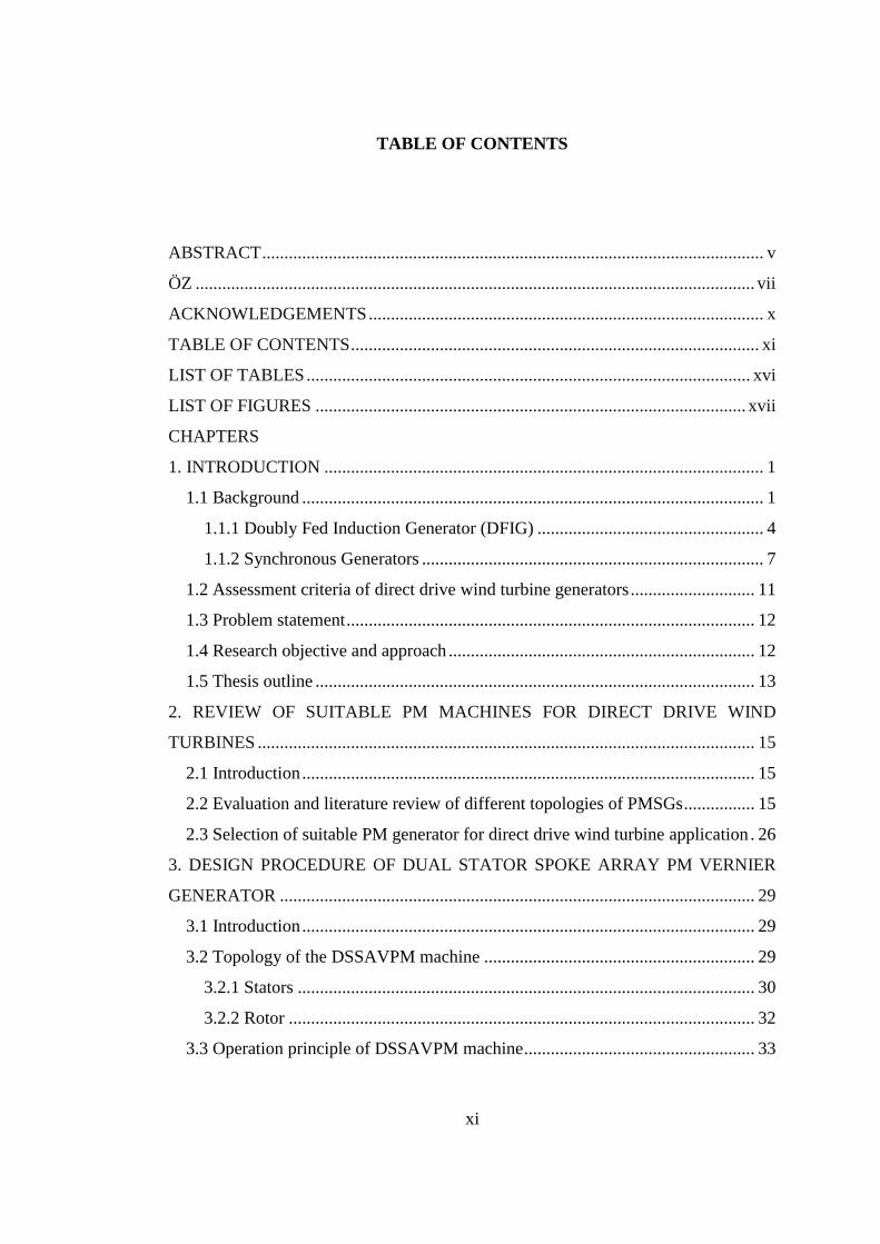
TABLE OF CONTENTS
ABSTRACT ................................................................................................................. v
ÖZ .............................................................................................................................. vii
ACKNOWLEDGEMENTS ......................................................................................... x
TABLE OF CONTENTS ............................................................................................ xi
LIST OF TABLES .................................................................................................... xvi
LIST OF FIGURES ................................................................................................. xvii
CHAPTERS
1. INTRODUCTION ................................................................................................... 1
1.1 Background ........................................................................................................ 1
1.1.1 Doubly Fed Induction Generator (DFIG) ................................................... 4
1.1.2 Synchronous Generators ............................................................................. 7
1.2 Assessment criteria of direct drive wind turbine generators ............................ 11
1.3 Problem statement ............................................................................................ 12
1.4 Research objective and approach ..................................................................... 12
1.5 Thesis outline ................................................................................................... 13
2. REVIEW OF SUITABLE PM MACHINES FOR DIRECT DRIVE WIND
TURBINES ................................................................................................................ 15
2.1 Introduction ...................................................................................................... 15
2.2 Evaluation and literature review of different topologies of PMSGs ................ 15
2.3 Selection of suitable PM generator for direct drive wind turbine application . 26
3. DESIGN PROCEDURE OF DUAL STATOR SPOKE ARRAY PM VERNIER
GENERATOR ........................................................................................................... 29
3.1 Introduction ...................................................................................................... 29
3.2 Topology of the DSSAVPM machine ............................................................. 29
3.2.1 Stators ....................................................................................................... 30
3.2.2 Rotor ......................................................................................................... 32
3.3 Operation principle of DSSAVPM machine .................................................... 33
xii
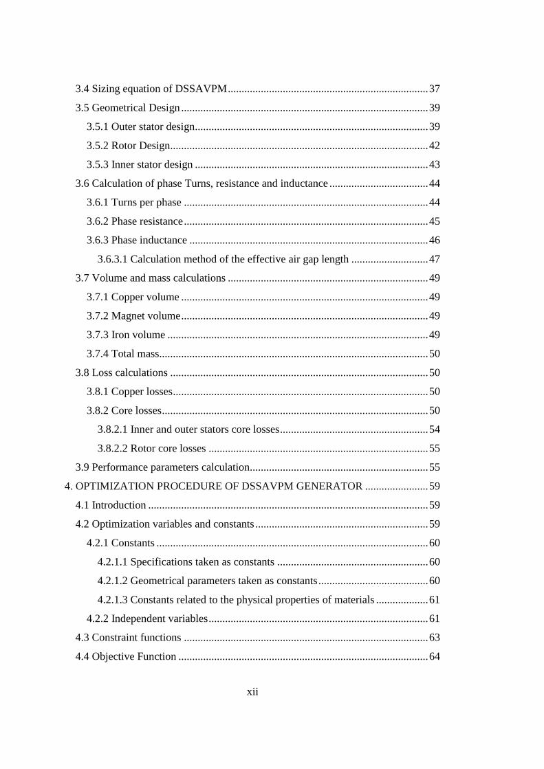
3.4 Sizing equation of DSSAVPM ......................................................................... 37
3.5 Geometrical Design .......................................................................................... 39
3.5.1 Outer stator design..................................................................................... 39
3.5.2 Rotor Design.............................................................................................. 42
3.5.3 Inner stator design ..................................................................................... 43
3.6 Calculation of phase Turns, resistance and inductance .................................... 44
3.6.1 Turns per phase ......................................................................................... 44
3.6.2 Phase resistance ......................................................................................... 45
3.6.3 Phase inductance ....................................................................................... 46
3.6.3.1 Calculation method of the effective air gap length ............................ 47
3.7 Volume and mass calculations ......................................................................... 49
3.7.1 Copper volume .......................................................................................... 49
3.7.2 Magnet volume .......................................................................................... 49
3.7.3 Iron volume ............................................................................................... 49
3.7.4 Total mass.................................................................................................. 50
3.8 Loss calculations .............................................................................................. 50
3.8.1 Copper losses ............................................................................................. 50
3.8.2 Core losses ................................................................................................. 50
3.8.2.1 Inner and outer stators core losses ...................................................... 54
3.8.2.2 Rotor core losses ................................................................................ 55
3.9 Performance parameters calculation................................................................. 55
4. OPTIMIZATION PROCEDURE OF DSSAVPM GENERATOR ....................... 59
4.1 Introduction ...................................................................................................... 59
4.2 Optimization variables and constants ............................................................... 59
4.2.1 Constants ................................................................................................... 60
4.2.1.1 Specifications taken as constants ....................................................... 60
4.2.1.2 Geometrical parameters taken as constants ........................................ 60
4.2.1.3 Constants related to the physical properties of materials ................... 61
4.2.2 Independent variables ................................................................................ 61
4.3 Constraint functions ......................................................................................... 63
4.4 Objective Function ........................................................................................... 64
xiii
4.5 Handling of the optimization problem ............................................................. 65
4.6 Optimization Flow chart .................................................................................. 66
4.6.1 Specifications of constants and design criteria subprocess ....................... 66
4.6.2 Calculation of the average flux densities using FEM software (box 5 and
box 6) ................................................................................................................. 68
4.6.3 Analytic calculations using MATLAB ..................................................... 71
4.6.4 Optimization method and tool (box 13 and box 14) ................................. 72
4.7 Conclusion ....................................................................................................... 75
5. DESIGN AND OPTIMIZATION PROCEDURE OF RFPM GENERATOR ...... 77
5.1 Introduction ...................................................................................................... 77
5.2 Sizing equation of the RFPM generator ........................................................... 78
5.3 Calculations of geometrical dimensions and parameters ................................. 80
5.4 Winding design ................................................................................................ 83
5.5 Determination of equivalent circuit parameters ............................................... 84
5.5.1 Phase resistance ........................................................................................ 84
5.5.2 Phase inductance ....................................................................................... 85
5.6 Losses and efficiency Calculation .................................................................... 85
5.6.1 Core losses ................................................................................................ 85
5.6.2 Resistive losses ......................................................................................... 86
5.6.3 Efficiency .................................................................................................. 87
5.7 Calculation of the generator mass .................................................................... 87
5.8 Optimization procedure of the RFPM generator .............................................. 88
5.8.1 Optimization constants .............................................................................. 88
5.8.1.1 Design specification taken as constant............................................... 88
5.8.1.2 Constants related to geometrical parameters ..................................... 89
5.8.1.3 Constants related to materials properties ........................................... 89
5.8.2 Independent variables and parameters ...................................................... 89
5.8.3 Constraint functions .................................................................................. 91
5.8.4 Objective function ..................................................................................... 92
5.8.5 Handling of the optimization problem ...................................................... 92
5.8.5.1 Optimization method ......................................................................... 92
xiv
5.8.5.2 Optimization algorithm and flowchart ............................................... 93
6. ACTIVE MASS OPTIMIZATION RESULTS FOR THE DSSAVPM AND RFPM
GENERATORS .......................................................................................................... 95
6.1 Introduction ...................................................................................................... 95
6.2 Active mass optimization of the DSSAVPM generator ................................... 95
6.2.1 Possible choices for GR ............................................................................ 96
6.2.2 Penalty coefficients and GA specifications ............................................... 97
6.2.3 Optimization results .................................................................................. 97
6.2.4 Selection of optimum GR and results discussion ...................................... 99
6.3 Active mass optimization of the RFPM generator ......................................... 102
6.3.1 Optimization results ................................................................................ 103
6.4 Comparison of the optimized DSSAVPM and RFPM generators ................. 104
6.5 A discussion about structural mass significance ............................................ 105
6.6 Conclusion ...................................................................................................... 106
7. INVESTIGATION OF STRUCTURAL MASS CONTRIBUTION TO OVERALL
WEIGHT OF RFPM AND DSSAVPM DIRECT DRIVE GENERATORS ........... 109
7.1 Introduction .................................................................................................... 109
7.2 Mechanical structure of the RFPM generator ................................................ 110
7.3 Mechanical structure of the DSSAVPM generator ........................................ 115
7.4 Calculating structural geometry for the optimized generators of chapter 6 ... 117
7.5 Results and discussions .................................................................................. 118
7.6 Conclusion ...................................................................................................... 121
8. TOTAL MASS OPTIMIZATION RESULTS OF THE DSSAVPM AND RFPM
GENERATORS ........................................................................................................ 123
8.1 Introduction .................................................................................................... 123
8.2 Total mass optimization results of the DSSAVPM generator ........................ 124
8.2.1 Optimum GR selection ............................................................................ 125
8.3 Total mass optimization results of the RFPM generator ................................ 126
8.4 Comparison of the optimized DSSAVPM and RFPM generators ................. 127
8.5 Performance analysis of the optimum generator ............................................ 128
9. CONCLUSION AND FUTURE WORKS ........................................................... 133
xv
9.1 Conclusion ..................................................................................................... 133
9.2 Future works .................................................................................................. 134
REFERENCES ........................................................................................................ 135
APPENDICES
A. CHARACTERISTICS OF CONSIDERED WIND TURBINE .......................... 139
xvi
LIST OF TABLES
TABLES
Table 1-1. Large capacity wind turbine systems in the market .................................... 5
Table 2-1. Summary of the surveyed PM machines characteristics ........................... 27
Table 3-1. Utilized core losses data for calculation of core losses coefficient .......... 52
Table 5-1. Constant dimensions and parameters used in the calculation of
geometrical parameters....................................................................................... 81
Table 5-2. Relations of geometrical dimensions and parameters ............................... 82
Table 5-3. Winding distribution inside stator slots under a pole pair for RFPM
generator ............................................................................................................. 84
Table 6-1. Penalty coefficients and GA specifications for optimization of the
DSSAVPM generator ......................................................................................... 97
Table 6-2. Mass optimization results of the DSSAVPM generator ........................... 98
Table 6-3. Penalty coefficients and GA specifications for optimization of the RFPM
generator ........................................................................................................... 102
Table 6-4. Active-mass optimization results of the RFPM generator ...................... 104
Table 7-1. Fixed constants and dimensions in structural geometry calculation ....... 118
Table 7-2. Dimensions and weights of the designed mechanical structure for the
RFPM generator ............................................................................................... 119
Table 7-3. DSSAVPM generator supporting structure weights ............................... 119
Table 8-1. Total mass optimization results of the DSSAVPM generators ............... 125
Table 8-2. Mechanical structure dimensions of the optimized DSSAVPM generators
.......................................................................................................................... 126
Table 8-3. Total mass optimization results for the RFPM generator ....................... 127
Table 8-4. Designed structural geometry dimensions for the RFPM generator ....... 127
Table 8-5. Characteristics of utilized wind turbine system ...................................... 131
xvii
LIST OF FIGURES
FIGURES
Figure 1-1. Variable speed wind turbine concept with DFIG ...................................... 6
Figure 1-2. Surface mounted Radial Flux Permanent Magnet (RFPM) machine ........ 9
Figure 1-3. Double stator AFPM machine ................................................................. 10
Figure 1-4. Topology of a TFPM machine ................................................................ 10
Figure 1-5. Surface mounted PMVM ........................................................................ 11
Figure 2-1. Conventional RFPM machine ................................................................. 16
Figure 2-2. Flux-Concentrated TFPM machines ....................................................... 16
Figure 2-3. (a) RFPM. (b)Multistage AFPM. (c) Three phase TFPM machines ....... 17
Figure 2-4. (a) Claw pole TFPM motor, (b) AFPM motor, (c) RFPM motor with
embedded PM in rotor ...................................................................................... 19
Figure 2-5. Reluctance torque Vernier machine ....................................................... 20
Figure 2-6. PM Vernier motor with magnets on both rotor and stator sides ............. 21
Figure 2-7. Surface permanent magnet Vernier machine ......................................... 22
Figure 2-8. Outer rotor permanent magnet Vernier machine .................................... 23
Figure 2-9. Dual side permanent magnet Vernier machine ....................................... 24
Figure 2-10. Magnetically geared pseudo direct-drive machine ............................... 25
Figure 2-11. Dual Stator Spoke-Array Vernier Permanent-Magnet ......................... 26
Figure 3-1. Configuration of dual stator permanent magnet Vernier machine .......... 30
Figure 3-2. Flux lines in the DSSAVPM machine .................................................... 30
Figure 3-3. Flux lines the DSSAVPM machine without inner stator ........................ 31
Figure 3-4. Inner and outer stators displacement ...................................................... 32
Figure 3-5. Configuration of DSSAVPM rotor ......................................................... 32
Figure 3-6. PM Vernier machine with horizontal flux lines ...................................... 34
Figure 3-7. PM Vernier machine with vertical flux line ............................................ 34
Figure 3-8. Geometrical dimensions of outer stator .................................................. 40
xviii
Figure 3-9. DSSAVPM rotor geometry and parameters ............................................ 42
Figure 3-10. Inner stator geometry and dimension parameters .................................. 43
Figure 3-11. The equivalent magnetic circuit of DSSAVPM generator under a pole
pair ...................................................................................................................... 46
Figure 3-12. Flux scattering coefficient versus slot length to gap-length ratio .......... 48
Figure 3-13. B-H characteristic of used core material ............................................... 52
Figure 3-14. Calculated and actual data of material core losses ................................ 53
Figure 3-15. Equivalent circuit of synchronous machine ........................................... 56
Figure 3-16. Vector diagram of proposed Vernier machine ...................................... 56
Figure 4-1. Optimization flow chart of the DSSAVPM generator ............................. 67
Figure 4-2. Primary FEM model of 4-pole DSSAVPM with gearing ratio of 11 ...... 69
Figure 4-3. Magnetic flux lines of DSSAVPM .......................................................... 70
Figure 5-1. Schematic view of Radial Flux Permanent Magnet machine .................. 77
Figure 5-2. Magnet span and resulting air gap flux density ....................................... 79
Figure 5-3. Surface mounted permanent magnet generator and its geometrical
dimensions .......................................................................................................... 80
Figure 5-4. Optimization flow chart of the RFPM generator ..................................... 94
Figure 6-1. Mass optimization convergence to the minimum fitness function .......... 98
Figure 6-2. Mass of the optimized DSSAVPM generator for three GRs ................... 99
Figure 6-3. Power factor of the optimized DSSAVPM generator versus GR .......... 100
Figure 6-4. Magnet mass, magnet cost and total cost versus GR ............................. 101
Figure 6-5. Efficiency of the optimized DSSAVPM generator for different GRs ... 101
Figure 6-6. Active material mass of the RFPM generator versus optimization
iterations ........................................................................................................... 103
Figure 6-7. Comparison of the optimized DSSAVPM_5 and RFPM generators .... 105
Figure 6-8. Comparison of bore diameter and occupied space of the RFPM and
DSSAVPM generators ..................................................................................... 106
Figure 7-1. Topology of the RFPM generator .......................................................... 110
Figure 7-2. (a) Rotor support structure of RFPM machine, (b) Stator support
structure of RFPM machine ............................................................................. 111
xix
Figure 7-3. (a) Illustration of centripetal force and tangential deflection (b)
illustration of normal component of Maxwell stress and normal deflection ... 112
Figure 7-4. (a) Transparent view of hollow torque arms, (b) Cross section view of
torque arms (c) 3D view of torque arms and cylindrical frame ....................... 113
Figure 7-5. Rotor of DSSAVPM generator and rotor mechanical structure ............ 116
Figure 7-6. Simplified 2D view of the rotor and its mechanical structure............... 117
Figure 7-7. Calculated structural mass versus outer diameter for the RFPM and
DSSAVPM generators ..................................................................................... 120
Figure 7-8. Comparison of the optimized generators in the terms of their active mass
structural mass and total mass .......................................................................... 120
Figure 8-1. Total mass optimization convergence to optimum solution in DSSAVPM
generator .......................................................................................................... 124
Figure 8-2. Comparison of the optimized DSSAVPM generators........................... 128
Figure 8-3. Electromagnetic torque of the designed generator ................................ 129
Figure 8-4. Cogging torque of designed generator .................................................. 130
Figure 8-5. Cogging torque of the designed RFPM machine .................................. 130
Figure 8-6. Power factor versus wind power characteristics of the designed generator
.......................................................................................................................... 131
Figure 8-7. Efficiency versus wind power characteristics of the designed generator
.......................................................................................................................... 132
Figure A. 1. Wind turbine power versus wind speed ............................................... 139
Figure A. 2.power coefficient versus tip speed ratio ............................................... 139
Figure A. 3. Power-speed characteristics of wind turbine for three wind speeds .... 140

1
CHAPTER 1
INTRODUCTION
1.1 Background
Wind power has been utilized for at least 3000 years. Until the early twentieth
century wind power was used to provide mechanical energy for pumping water and
grinding grains. But at the beginning of industrialization fluctuating wind power
resource was replaced by fuel fired engines or electrical grid, which provides more
reliable power source. In the early 1970s, with the first oil price shock, interest in the
wind power re-emerged. This time, however main focus was on wind power providing
electrical energy instead of mechanical energy. Furthermore, negative effects of fossil
fuels on global warming have made it important to harvest renewable energy such as
wind energy. With the current technology wind energy produces electricity cheaper
than other renewable energy sources, so it has achieved fastest growth. Wind energy
has the potential to play an important role in the future energy supply. Within the past
two decades, wind turbine technology has reached very reliable and sophisticated
level. The growing worldwide market is leading to further improvement, larger wind
turbines and new system application (e. g. offshore wind farms). As a result of these
improvements, further cost reduction is obtained and in the medium term wind energy
will be able to compete with conventional fossil fuel power generation technology.
Therefore, further researches are required to be done in this area to achieve such goals.
In order to maximize harnessed energy, minimize the cost and improve power
quality and reliability, different wind turbine electric energy conversion concepts have
been proposed during last three decades. Wind turbine electric energy conversion
concepts can be classified into the fixed speed systems, the limited variable speed
systems and the variable speed systems, considering the turbine rotational speed. Until
2
the late 1990s, fixed-speed stall-controlled wind turbines with squirrel cage induction
generators and a three stage gearbox were prominent. In spite of simplicity, reliability
and lower cost of fixed-speed concept, it has some drawbacks such as high mechanical
stress on rotor blades and limited power quality.
In order to defeat the disadvantages of fixed speed concept, instead of fixed
speed wind turbines variable speed pitch-controlled wind turbine technology systems
found common application. Variable speed wind turbines make it possible to achieve
maximum aerodynamic efficiency over a wide range of wind speeds and allow the
turbine to accelerate and store energy during wind gusts [1, 2]. The variable speed
wind turbines have become the dominant type among the installed generators in the
past few years. Contrary to a fixed speed system, a variable speed system maintains
the generator torque fairly constant and variations in the wind power are absorbed by
changes in the generator speed.
The electrical system of the variable speed turbine electrical energy conversion
configuration is more complicated than the fixed speed concept. The Induction or
synchronous generator may be utilized in the variable speed configuration to convert
the mechanical power to the electricity. In the variable speed concept, the generator
output is connected to the grid through a power converter. The task of the power
converter is to adjust the output frequency and voltage of the generator to the grid. The
generator output is rectified via a rectifier connected to a DC-link, then rectified
voltage is inverted to a three phase sinusoidal waveform via an inverter connected to
the grid. Increased energy capture, improved power quality and reduced mechanical
stress on turbine are advantages of variable speed wind turbine. Power converter
losses, the use of more components and increased cost of equipment are drawbacks of
variable speed concept [3].
Variable speed wind turbine energy conversion systems can be classified into
geared drive and direct drive types from the drive train point of view. In a wind turbine
with geared generator system, turbine hub is connected to the generator shaft via an
incremental gearbox to increase the shaft speed. While, in direct drive systems, turbine
hub is directly connected to the generator shaft, thus direct drive generator operates at
low speed. Both of these two systems have their own advantages and disadvantages.
3
In geared configuration, due to high rotational speed, generator torque rating is
inversely decreased, in proportion to rotational speed. Generally, generators’ torque is
proportional to the square of bore diameter, in other words generators with lower
torque rating have smaller bore diameters. Thus, utilizing a gearbox has the advantage
of smaller generator with smaller mass and lower cost. Although, geared wind turbine
concept makes the generator very cost-efficient, gearbox imposes some considerable
drawbacks to the system. First of all, it is a large and heavy structure, so it increases
the size of wind turbine nacelle and subsequently increases overall mass of wind
turbine head. Second, it increases overall cost of wind turbine system, because it
should be provided and mounted in the system, independently. Third, gearbox is a
mechanical tool and requires regular maintenance and lubrication, so it exerts extra
cost to the system. Finally, gearbox creates audible noise and sound pollution [4].
The alternative for geared wind turbine concept is the direct drive
configuration. The rotor of direct drive generator is directly connected to wind turbine
hub, so that the rotational speed of generator is low. Due to this low speed generator
torque rating increases, which means a generator with large diameter must be used.
The major merit of direct drive configuration is elimination of the gearbox. Moreover,
variable speed direct drive concept has the advantages of higher efficiency, higher
energy yield, higher reliability and low noise and maintenance cost. Besides these
advantages, elimination of gearbox imposes some disadvantages to the system. Large
diameter, large mass and high-cost generator are the principal drawbacks of direct
drive wind turbine configuration [5-7]. Thus, it is very crucial to utilize high torque
density generators in direct drive wind turbine to make the system cost effective. In
order to compensate disadvantages of direct drive concept, generators are usually
designed with a large diameter and small pole pitch [4]. Furthermore, in Turkey only
small size gearboxes are produced, therefore direct drive technology has the advantage
of using local machinery companies in production.
Basically, a wind turbine can be equipped with any type of three phase
generators. The following generator systems are the most common utilized generators
for variable-speed geared wind turbine concept for both geared drive and direct drive
concepts.
4
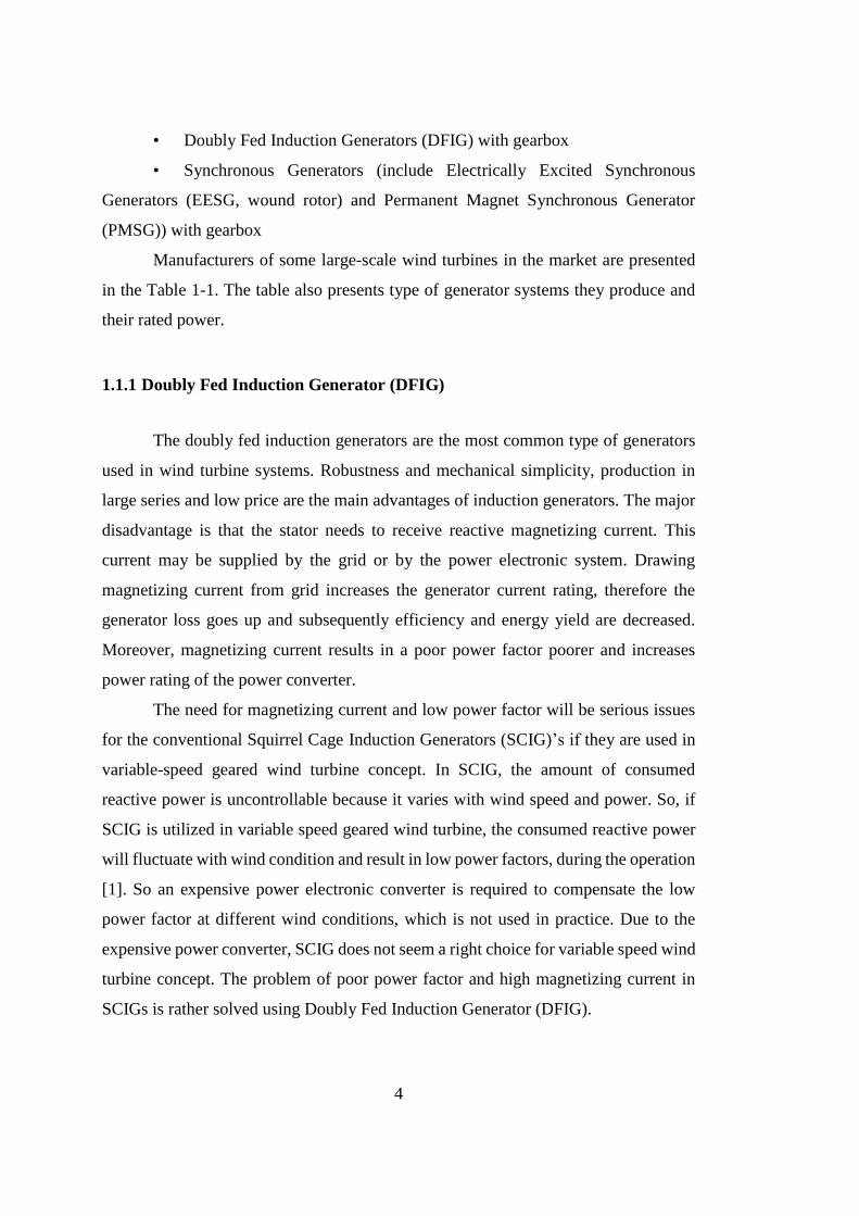
• Doubly Fed Induction Generators (DFIG) with gearbox
• Synchronous Generators (include Electrically Excited Synchronous
Generators (EESG, wound rotor) and Permanent Magnet Synchronous Generator
(PMSG)) with gearbox
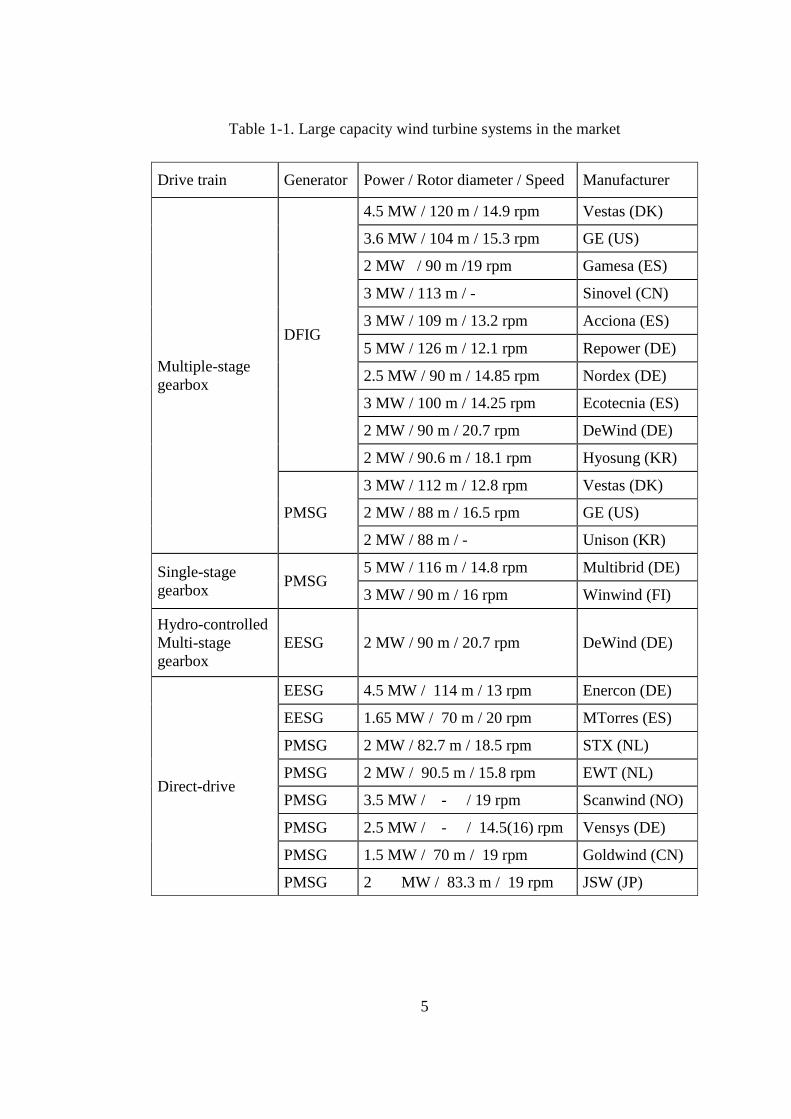
Manufacturers of some large-scale wind turbines in the market are presented
in the Table 1-1. The table also presents type of generator systems they produce and
their rated power.
1.1.1 Doubly Fed Induction Generator (DFIG)
The doubly fed induction generators are the most common type of generators
used in wind turbine systems. Robustness and mechanical simplicity, production in
large series and low price are the main advantages of induction generators. The major
disadvantage is that the stator needs to receive reactive magnetizing current. This
current may be supplied by the grid or by the power electronic system. Drawing
magnetizing current from grid increases the generator current rating, therefore the
generator loss goes up and subsequently efficiency and energy yield are decreased.
Moreover, magnetizing current results in a poor power factor poorer and increases
power rating of the power converter.
The need for magnetizing current and low power factor will be serious issues
for the conventional Squirrel Cage Induction Generators (SCIG)’s if they are used in
variable-speed geared wind turbine concept. In SCIG, the amount of consumed
reactive power is uncontrollable because it varies with wind speed and power. So, if
SCIG is utilized in variable speed geared wind turbine, the consumed reactive power
will fluctuate with wind condition and result in low power factors, during the operation
[1]. So an expensive power electronic converter is required to compensate the low
power factor at different wind conditions, which is not used in practice. Due to the
expensive power converter, SCIG does not seem a right choice for variable speed wind
turbine concept. The problem of poor power factor and high magnetizing current in
SCIGs is rather solved using Doubly Fed Induction Generator (DFIG).
5
Table 1-1. Large capacity wind turbine systems in the market
Drive train Generator Power / Rotor diameter / Speed Manufacturer
Multiple-stage
gearbox
DFIG
4.5 MW / 120 m / 14.9 rpm Vestas (DK)
3.6 MW / 104 m / 15.3 rpm GE (US)
2 MW / 90 m /19 rpm Gamesa (ES)
3 MW / 113 m / - Sinovel (CN)
3 MW / 109 m / 13.2 rpm Acciona (ES)
5 MW / 126 m / 12.1 rpm Repower (DE)
2.5 MW / 90 m / 14.85 rpm Nordex (DE)
3 MW / 100 m / 14.25 rpm Ecotecnia (ES)
2 MW / 90 m / 20.7 rpm DeWind (DE)
2 MW / 90.6 m / 18.1 rpm Hyosung (KR)
PMSG
3 MW / 112 m / 12.8 rpm Vestas (DK)
2 MW / 88 m / 16.5 rpm GE (US)
2 MW / 88 m / - Unison (KR)
Single-stage
gearbox PMSG
5 MW / 116 m / 14.8 rpm Multibrid (DE)
3 MW / 90 m / 16 rpm Winwind (FI)
Hydro-controlled
Multi-stage
gearbox
EESG 2 MW / 90 m / 20.7 rpm DeWind (DE)
Direct-drive
EESG 4.5 MW / 114 m / 13 rpm Enercon (DE)
EESG 1.65 MW / 70 m / 20 rpm MTorres (ES)
PMSG 2 MW / 82.7 m / 18.5 rpm STX (NL)
PMSG 2 MW / 90.5 m / 15.8 rpm EWT (NL)
PMSG 3.5 MW / - / 19 rpm Scanwind (NO)
PMSG 2.5 MW / - / 14.5(16) rpm Vensys (DE)
PMSG 1.5 MW / 70 m / 19 rpm Goldwind (CN)
PMSG 2 MW / 83.3 m / 19 rpm JSW (JP)
6
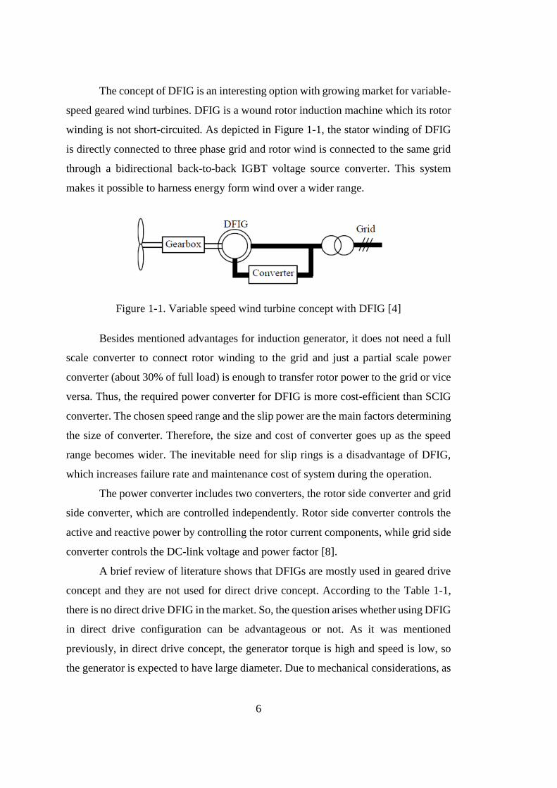
The concept of DFIG is an interesting option with growing market for variable-
speed geared wind turbines. DFIG is a wound rotor induction machine which its rotor
winding is not short-circuited. As depicted in Figure 1-1, the stator winding of DFIG
is directly connected to three phase grid and rotor wind is connected to the same grid
through a bidirectional back-to-back IGBT voltage source converter. This system
makes it possible to harness energy form wind over a wider range.
Figure 1-1. Variable speed wind turbine concept with DFIG [4]
Besides mentioned advantages for induction generator, it does not need a full
scale converter to connect rotor winding to the grid and just a partial scale power
converter (about 30% of full load) is enough to transfer rotor power to the grid or vice
versa. Thus, the required power converter for DFIG is more cost-efficient than SCIG
converter. The chosen speed range and the slip power are the main factors determining
the size of converter. Therefore, the size and cost of converter goes up as the speed
range becomes wider. The inevitable need for slip rings is a disadvantage of DFIG,
which increases failure rate and maintenance cost of system during the operation.
The power converter includes two converters, the rotor side converter and grid
side converter, which are controlled independently. Rotor side converter controls the
active and reactive power by controlling the rotor current components, while grid side
converter controls the DC-link voltage and power factor [8].
A brief review of literature shows that DFIGs are mostly used in geared drive
concept and they are not used for direct drive concept. According to the Table 1-1,
there is no direct drive DFIG in the market. So, the question arises whether using DFIG
in direct drive configuration can be advantageous or not. As it was mentioned
previously, in direct drive concept, the generator torque is high and speed is low, so
the generator is expected to have large diameter. Due to mechanical considerations, as
7
generator diameter increases, air gap length should become larger. An induction
machine with large air gap has smaller magnetizing inductance, so magnetizing current
goes up and subsequently generator losses rises. As it was discussed previously, having
high efficiency and energy yield are critical factors for direct drive wind turbine
generators to compensate the extra cost imposed to the system because of large
diameter and large mass of direct drive generator. Therefore, the DFIG does not seem
a proper choice for direct drive application form efficiency and energy yield point of
view.
1.1.2 Synchronous Generators
Synchronous generator is much more expensive and mechanically more
complicated than an induction generator of a similar size. Full scale power converter
and high converter losses are other two drawbacks of this generator. However, it has
one clear advantage compared with DFIG that it does not a reactive magnetizing
current, so it has the advantages of better efficiency and higher energy yield in
comparison with DFIGs. Similar to DFIGs, synchronous generators can be used in
both geared and direct drive wind turbine configurations.
Because of high rotational speed and low torque rating in geared drive concept
compared with direct drive concept, the generator of geared drive concept is expected
to have smaller diameter. DFIGs with small diameters have smaller air gap and
subsequently smaller magnetizing current, so their losses are lower with respect to
DFIGs with large diameters. Therefore, it can be concluded that DFIGs can compete
with synchronous generators from efficiency and energy yield point of view, when
they are utilized in geared wind turbine concept. On the other hand, DFIGs need partial
scale converter to be connected to the grid while synchronous generators require a full
scale power converter for grid connection. Thus DFIGs sound to be more
advantageous than synchronous generator, for geared wind turbine application.
However, the story changes when it comes to direct drive concept [5].
In direct drive configuration, due to the direct connection of generator shaft
and wind turbine hub, rotational speed is low and rating torque is high. Consequently,
8
direct drive generator is expected to have large diameter. As it was discussed before,
DFIGs with large diameter and air gap length have high magnetizing current and suffer
from lower efficiency and energy yield in comparison to synchronous generators.
Although DFIGs have the advantage of partial scale power converter but their low
efficiency and energy yield makes it difficult for DFIGs to compete with synchronous
generator in direct drive wind turbine concept. As a conclusion, it can be stated that,
although synchronous generators need an expensive and full scale power converter,
their high efficiency and energy yield makes them more advantageous than DFIGs for
direct drive wind turbine application.
Direct drive Synchronous generators available on the market can be classified
into two main categories, Electrically Excited Synchronous Generators (EESG) and
Permanent Magnet Synchronous Generator (PMSG).
EESGs are excited by a DC field winding mounted on rotor side. Slip ring and
brushes or brushless exciter are used for DC excitation. The stator winding is similar
to winding of induction machine. Stator winding is connected to the grid through a full
scale power converter. The amplitude and frequency of generator output voltage can
be controlled independent of the grid. Due to controllable field excitation, active and
reactive power can be also fully controlled [6].
The operation principle of Permanent Magnet Synchronous Generator (PMSG)
is similar to EESG but field excitation is created by permanent magnets in PMSG.
Although EESG provides much more control options compared with PMSG, but
PMSG has the following advantages with respect to EESG [4],
• Higher efficiency and energy yield
• No additional power supply for field excitation
• Improved thermal characteristics due to the absence of field losses
• Higher reliability due to the absence of mechanical component such as slip
ring
• Light weight and higher torque density
The major disadvantages of PMSG are high cost of permanent magnets and
demagnetizing of permanent magnets at high temperature. However, in the recent
years, the performance of permanent magnets has improved and the cost of permanent
9
magnet has decreased. Furthermore, the cost of power electronic components is
decreasing. Thus, considering all aspects, it can be concluded that PMSG with full
scale converter is the most attractive option for direct drive wind turbine concept.
Permanent Magnet Synchronous Generators (PMSGs) have been classified
based on their flux path direction and electromagnetic construction as follows.
• Radial Flux Permanent Magnet machine (RFPM)
• Axial Flux Permanent Magnet machine (AFPM)
• Transverse Flux Permanent Magnet machine (TFPM)
• Permanent Magnet Vernier Machine (PMVM)
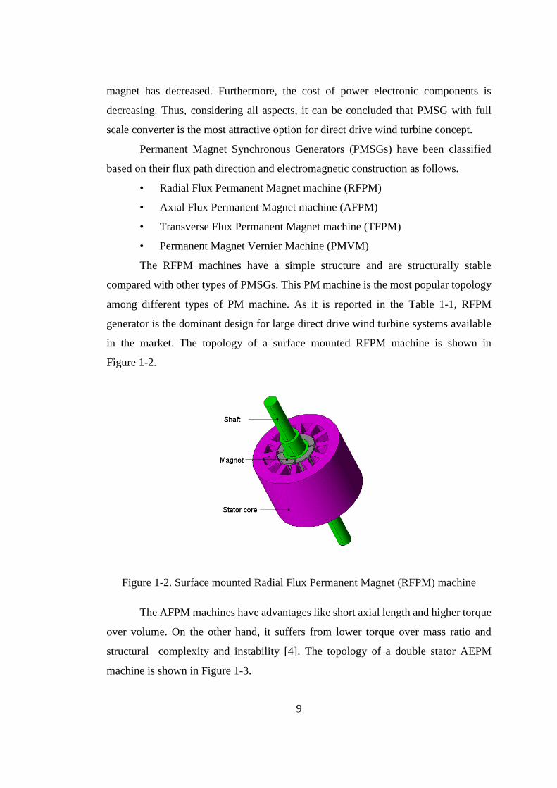
The RFPM machines have a simple structure and are structurally stable
compared with other types of PMSGs. This PM machine is the most popular topology
among different types of PM machine. As it is reported in the Table 1-1, RFPM
generator is the dominant design for large direct drive wind turbine systems available
in the market. The topology of a surface mounted RFPM machine is shown in
Figure 1-2.
Figure 1-2. Surface mounted Radial Flux Permanent Magnet (RFPM) machine
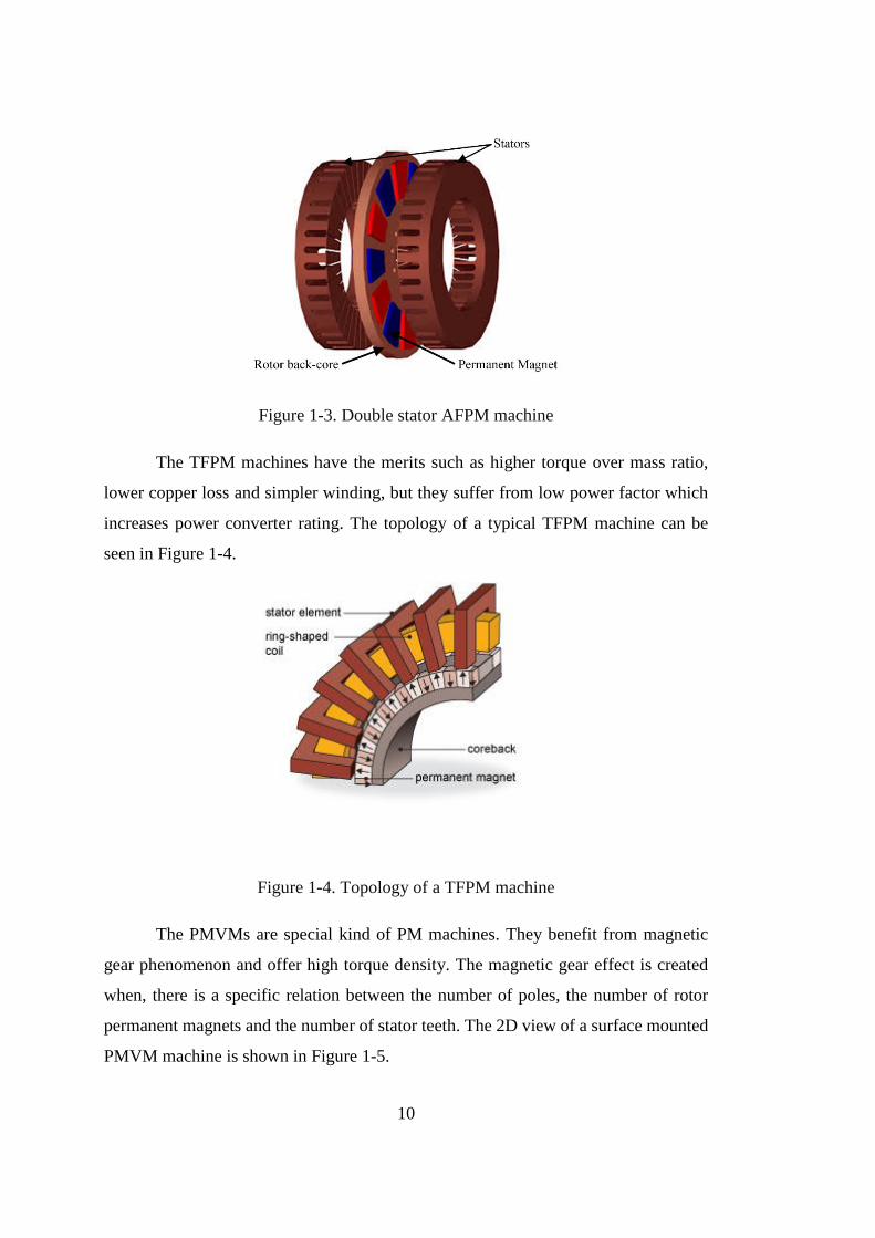
The AFPM machines have advantages like short axial length and higher torque
over volume. On the other hand, it suffers from lower torque over mass ratio and
structural complexity and instability [4]. The topology of a double stator AEPM
machine is shown in Figure 1-3.
10
Figure 1-3. Double stator AFPM machine
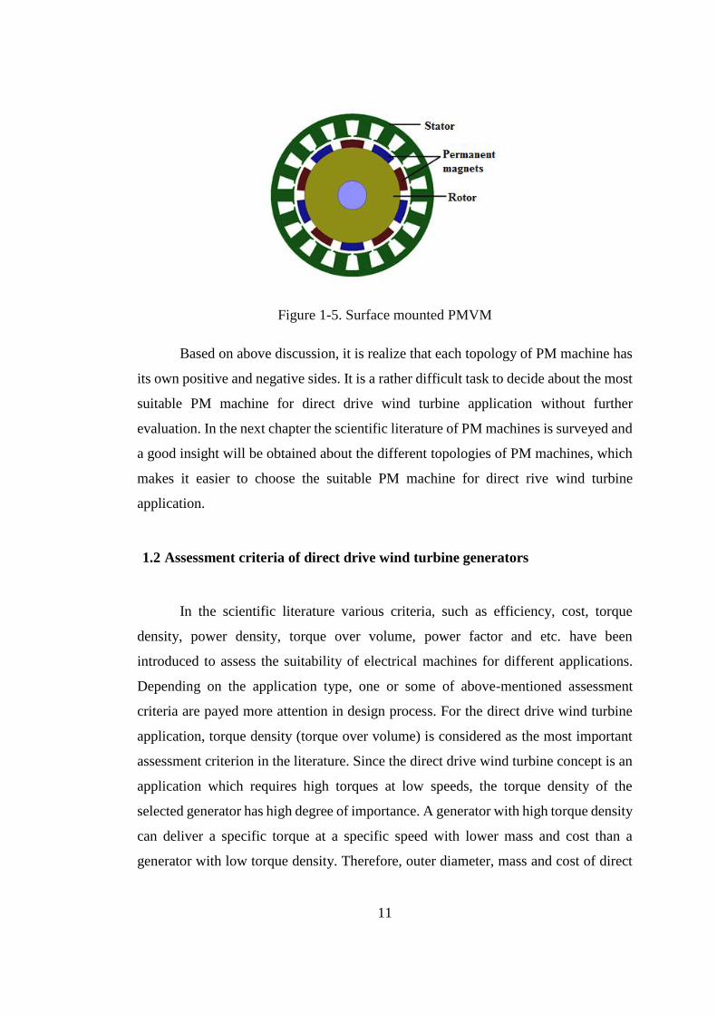
The TFPM machines have the merits such as higher torque over mass ratio,
lower copper loss and simpler winding, but they suffer from low power factor which
increases power converter rating. The topology of a typical TFPM machine can be
seen in Figure 1-4.
Figure 1-4. Topology of a TFPM machine
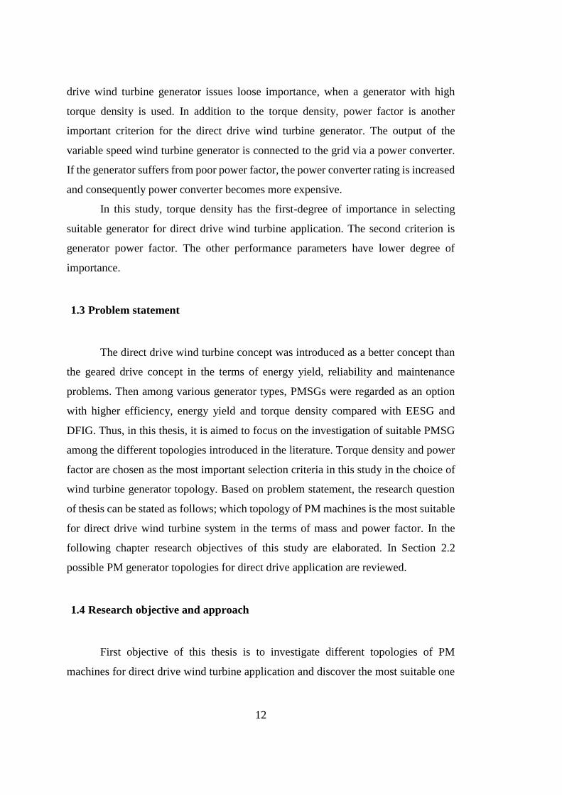
The PMVMs are special kind of PM machines. They benefit from magnetic
gear phenomenon and offer high torque density. The magnetic gear effect is created
when, there is a specific relation between the number of poles, the number of rotor
permanent magnets and the number of stator teeth. The 2D view of a surface mounted
PMVM machine is shown in Figure 1-5.
11
Figure 1-5. Surface mounted PMVM
Based on above discussion, it is realize that each topology of PM machine has
its own positive and negative sides. It is a rather difficult task to decide about the most
suitable PM machine for direct drive wind turbine application without further
evaluation. In the next chapter the scientific literature of PM machines is surveyed and
a good insight will be obtained about the different topologies of PM machines, which
makes it easier to choose the suitable PM machine for direct rive wind turbine
application.
1.2 Assessment criteria of direct drive wind turbine generators
In the scientific literature various criteria, such as efficiency, cost, torque
density, power density, torque over volume, power factor and etc. have been
introduced to assess the suitability of electrical machines for different applications.
Depending on the application type, one or some of above-mentioned assessment
criteria are payed more attention in design process. For the direct drive wind turbine
application, torque density (torque over volume) is considered as the most important
assessment criterion in the literature. Since the direct drive wind turbine concept is an
application which requires high torques at low speeds, the torque density of the
selected generator has high degree of importance. A generator with high torque density
can deliver a specific torque at a specific speed with lower mass and cost than a
generator with low torque density. Therefore, outer diameter, mass and cost of direct
12
drive wind turbine generator issues loose importance, when a generator with high
torque density is used. In addition to the torque density, power factor is another
important criterion for the direct drive wind turbine generator. The output of the
variable speed wind turbine generator is connected to the grid via a power converter.
If the generator suffers from poor power factor, the power converter rating is increased
and consequently power converter becomes more expensive.
In this study, torque density has the first-degree of importance in selecting
suitable generator for direct drive wind turbine application. The second criterion is
generator power factor. The other performance parameters have lower degree of
importance.
1.3 Problem statement
The direct drive wind turbine concept was introduced as a better concept than
the geared drive concept in the terms of energy yield, reliability and maintenance
problems. Then among various generator types, PMSGs were regarded as an option
with higher efficiency, energy yield and torque density compared with EESG and
DFIG. Thus, in this thesis, it is aimed to focus on the investigation of suitable PMSG
among the different topologies introduced in the literature. Torque density and power
factor are chosen as the most important selection criteria in this study in the choice of
wind turbine generator topology. Based on problem statement, the research question
of thesis can be stated as follows; which topology of PM machines is the most suitable
for direct drive wind turbine system in the terms of mass and power factor. In the
following chapter research objectives of this study are elaborated. In Section 2.2
possible PM generator topologies for direct drive application are reviewed.
1.4 Research objective and approach
First objective of this thesis is to investigate different topologies of PM
machines for direct drive wind turbine application and discover the most suitable one
13
in the terms of assessment criteria. Second objective is to design and optimize the
chosen topology for a specific wind turbine system and evaluate the suitability of the
chosen PM generator topology. The next issue is to compare this design with the
standard RF generator design and assess whether the proposed topology offers any
advantage. To achieve these goals, the following issues are covered in this thesis:
Various topologies of PMSGs are evaluated in the terms of torque density and
power factor
The most suitable PM machine is chosen for desired application among the
investigate PM machines
The chosen machine is designed and optimized for a specific wind turbine
(without the frame and with the frame).
A RFPM generator is designed for the same application to have a reference
for evaluation of the new design
The proposed topology is evaluated against the reference design
1.5 Thesis outline
In chapter two, scientific literature is surveyed and different permanent magnet
machine topologies are investigated to discover their suitability for direct drive wind
turbine application. Finally, among the investigated permanent magnet machines the
most suitable topology is selected to be designed for the desired application.
In chapter three, design process of the Dual Stator Spoke-Array Vernier
Permanent Magnet (DSSAVPM) generator is presented. Moreover, performance
analysis equations are also derived to be able evaluate the design generator.
In chapter four, an optimization procedure is developed for the DSSAVPM
generator. The proposed design process in chapter 3 are utilized in develop
optimization procedure to obtain the lightest DSSAVPM.
14
In chapter five, the design and optimization process of Radial Flux Permanent
Magnet (RFPM) generator is discussed. An analytic design procedure is presented for
the RFPM generator and the most light-weight RFPM generator is obtained using
proposed optimization procedure.
Chapter six includes active mass optimizations results for the DSSAVPM and
RFPM generator. The optimization results are compared and discussed to find the most
suitable generator for the direct drive wind turbine application. In this chapter the
significance of the structural mass in direct drive wind turbine generators is revealed.
In chapter seven, an analytic model is presented to estimate the structural
geometry of the DSSAVPM and RFPM generators. Then proposed method is utilized
to calculate structural mass of the optimized generators in chapter 6.
In chapter eight, the generators structural mass is taken into account in
optimizations and the generators are optimized for their total mass including active
materials mass and structural mass. At the end the optimized DSSAVPM and RFPM
generators are compared to discover the most optimum generator.
In chapter nine, conclusion of the study is given and some future works are
recommended.
15
CHAPTER 2
REVIEW OF SUITABLE PM MACHINES FOR DIRECT DRIVE WIND
TURBINES
2.1 Introduction
As it was discussed in pervious chapter, direct drive wind turbine concept can
compete with geared drive concept, if a generator system with both maximum energy
yield and minimum cost is utilized. According to previous chapter, PMSGs are
addressed as a solution with high energy yield, high reliability and fewer maintenance
cost. In his chapter, it is aimed to find the PMSG topology with highest torque density.
If it is possible to reduce the cost of direct drive PMSG to the DFIG with gearbox
without diminishing its performance, then the direct drive PMSG will be the most
suitable generator system. Generator cost is mainly dependent on its materials mass.
Therefore in this chapter, the mass-competitiveness of different topologies of PMSG
is evaluated. Categorized PMSGs in previous chapter are considered in this chapter.
2.2 Evaluation and literature review of different topologies of PMSGs
In [4], various topologies of PM machines are evaluated to discover a suitable
electrical machine for direct drive wind turbine application. To achieve this purpose,
the potential of different types of permanent magnet machines is evaluated for higher
torque density. In this study, the presented PM machines in scientific literature are
surveyed. Then, the ratios of active mass to torque are compared for surveyed machine.
Comparison shows that conventional RFPM and Flux-Concentrated TFPM
(FCTFPM) machines offer higher torque density than other types of electrical
machines. The topologies of RFPM and FCTFPM machines are shown in Figure 2-1
16
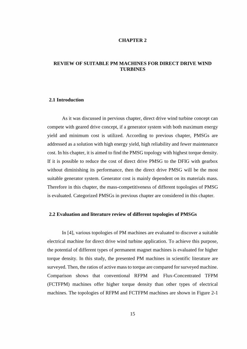
and Figure 2-2, respectively. After selection of right generators, the chosen RFPM and
FCTFPM machines are designed as generator for 5 MW and 10 MW wind turbine at
the speeds of 8.6 and 12.1 rpm, respectively. The design results show that FCTFPM
machine was reported as the lightest generator for 5 MW power rating, while, in the
design of the generator for 10 MW wind turbine, RFPM machines addressed as the
lightest machine [4]. In addition, low power factor is reported as a considerable
drawback for FCTFPM machines.
Figure 2-1. Conventional RFPM machine
Figure 2-2. Flux-Concentrated TFPM machines [4]
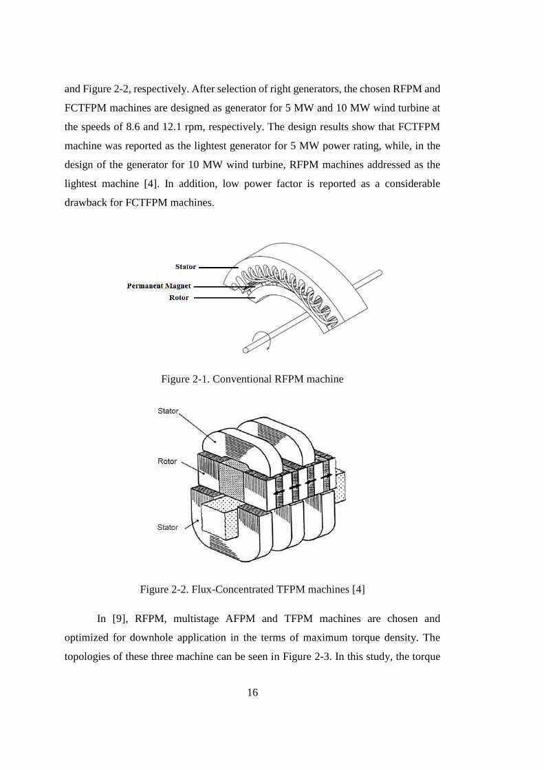
In [9], RFPM, multistage AFPM and TFPM machines are chosen and
optimized for downhole application in the terms of maximum torque density. The
topologies of these three machine can be seen in Figure 2-3. In this study, the torque
17
density is defined as torque over whole volume of the motor including end windings.
The chosen motors are optimized to achieve maximum torque density, while outer
diameters are restricted by well size. Design and optimization results indicate that
RFPM, multistage AFPM and TFPM machines are able to deliver maximum torque of
75, 50, 105 N.m at the constant speed of 1000 rpm, while they have same outer
diameter and axial length. In this study it is shown that the TFPM machine with larger
number of pole has the advantages of high torque density. However, as the number of
poles is increased, its power factor is deceased. Finally, it is concluded that RFPM
motor is the best choice for downhole application. Although the torque density of
TFPM motor is better than RFPM motor, but RFPM is more advantageous in the terms
of power factor and efficiency.
Figure 2-3. (a) RFPM. (b)Multistage AFPM. (c) Three phase TFPM machines [9]
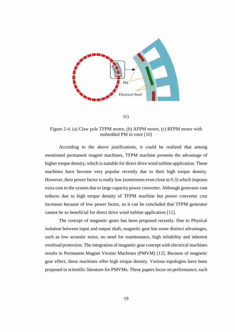
In [10], claw pole structure TFPM, AFPM and RFPM machines shown in the
Figure 2-4 are optimized and compared in the terms of torque density and mass-
competitiveness for electric vehicle application. The selected motors are optimized to
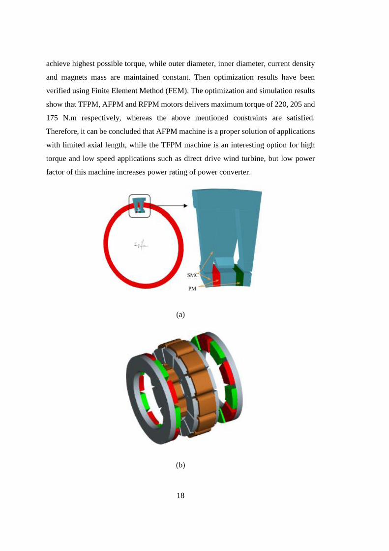
18
achieve highest possible torque, while outer diameter, inner diameter, current density
and magnets mass are maintained constant. Then optimization results have been
verified using Finite Element Method (FEM). The optimization and simulation results
show that TFPM, AFPM and RFPM motors delivers maximum torque of 220, 205 and
175 N.m respectively, whereas the above mentioned constraints are satisfied.
Therefore, it can be concluded that AFPM machine is a proper solution of applications
with limited axial length, while the TFPM machine is an interesting option for high
torque and low speed applications such as direct drive wind turbine, but low power
factor of this machine increases power rating of power converter.
(a)
(b)
19
(c)
Figure 2-4. (a) Claw pole TFPM motor, (b) AFPM motor, (c) RFPM motor with
embedded PM in rotor [10]
According to the above justifications, it could be realized that among
mentioned permanent magnet machines, TFPM machine presents the advantage of
higher torque density, which is suitable for direct drive wind turbine application. These
machines have become very popular recently due to their high torque density.
However, their power factor is really low (sometimes even close to 0.3) which imposes
extra cost to the system due to large capacity power converter. Although generator cost
reduces due to high torque density of TFPM machine but power converter cost
increases because of low power factor, so it can be concluded that TFPM generator
cannot be so beneficial for direct drive wind turbine application [11].
The concept of magnetic gears has been proposed recently. Due to Physical
isolation between input and output shaft, magnetic gear has some distinct advantages,
such as low acoustic noise, no need for maintenance, high reliability and inherent
overload protection. The integration of magnetic gear concept with electrical machines
results in Permanent Magnet Vernier Machines (PMVM) [12]. Because of magnetic
gear effect, these machines offer high torque density. Various topologies have been
proposed in scientific literature for PMVMs. These papers focus on performance, such
20
as efficiency, core losses, power factor and etc. to achieve a PMVM with acceptable
performance. A brief review of PMVMs evolution is given in the following.
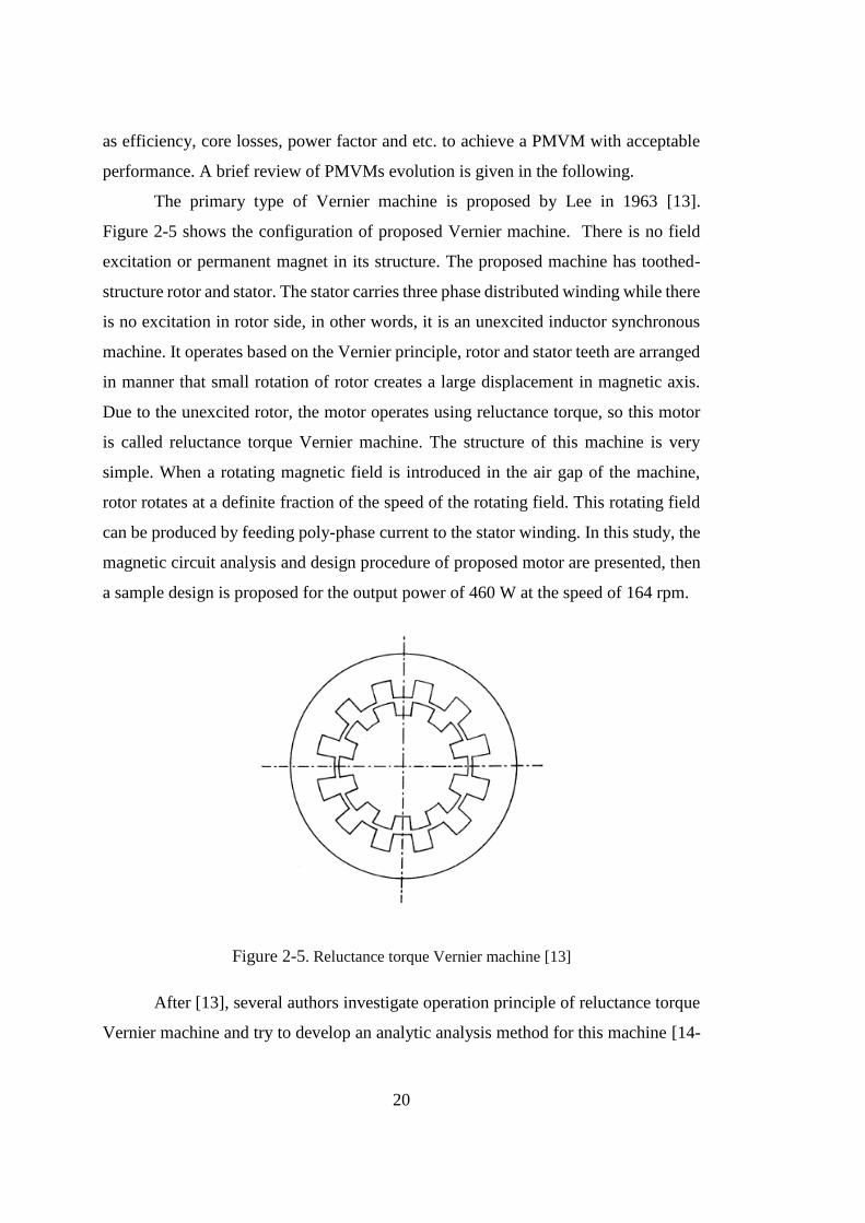
The primary type of Vernier machine is proposed by Lee in 1963 [13].
Figure 2-5 shows the configuration of proposed Vernier machine. There is no field
excitation or permanent magnet in its structure. The proposed machine has toothed-
structure rotor and stator. The stator carries three phase distributed winding while there
is no excitation in rotor side, in other words, it is an unexcited inductor synchronous
machine. It operates based on the Vernier principle, rotor and stator teeth are arranged
in manner that small rotation of rotor creates a large displacement in magnetic axis.
Due to the unexcited rotor, the motor operates using reluctance torque, so this motor
is called reluctance torque Vernier machine. The structure of this machine is very
simple. When a rotating magnetic field is introduced in the air gap of the machine,
rotor rotates at a definite fraction of the speed of the rotating field. This rotating field
can be produced by feeding poly-phase current to the stator winding. In this study, the
magnetic circuit analysis and design procedure of proposed motor are presented, then
a sample design is proposed for the output power of 460 W at the speed of 164 rpm.
Figure 2-5. Reluctance torque Vernier machine [13]
After [13], several authors investigate operation principle of reluctance torque
Vernier machine and try to develop an analytic analysis method for this machine [14-
21
16]. But, due to the poor power factor, lower torque density and uncertainly in regard
to design criteria, it does not attract more attention of researchers.
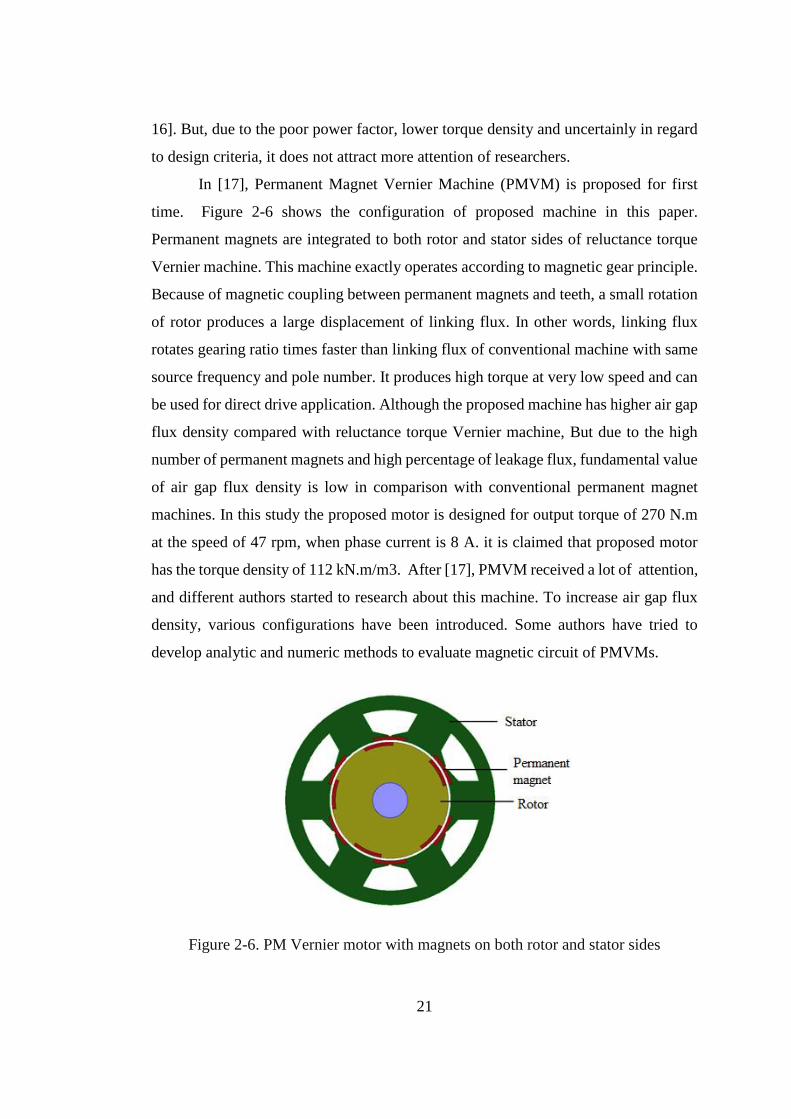
In [17], Permanent Magnet Vernier Machine (PMVM) is proposed for first
time. Figure 2-6 shows the configuration of proposed machine in this paper.
Permanent magnets are integrated to both rotor and stator sides of reluctance torque
Vernier machine. This machine exactly operates according to magnetic gear principle.
Because of magnetic coupling between permanent magnets and teeth, a small rotation
of rotor produces a large displacement of linking flux. In other words, linking flux
rotates gearing ratio times faster than linking flux of conventional machine with same
source frequency and pole number. It produces high torque at very low speed and can
be used for direct drive application. Although the proposed machine has higher air gap
flux density compared with reluctance torque Vernier machine, But due to the high
number of permanent magnets and high percentage of leakage flux, fundamental value
of air gap flux density is low in comparison with conventional permanent magnet
machines. In this study the proposed motor is designed for output torque of 270 N.m
at the speed of 47 rpm, when phase current is 8 A. it is claimed that proposed motor
has the torque density of 112 kN.m/m3. After [17], PMVM received a lot of attention,
and different authors started to research about this machine. To increase air gap flux
density, various configurations have been introduced. Some authors have tried to
develop analytic and numeric methods to evaluate magnetic circuit of PMVMs.
Figure 2-6. PM Vernier motor with magnets on both rotor and stator sides
22
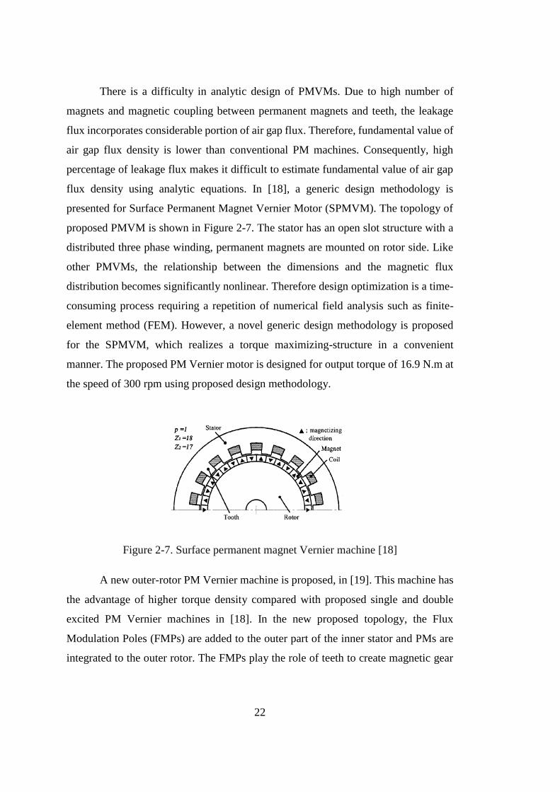
There is a difficulty in analytic design of PMVMs. Due to high number of
magnets and magnetic coupling between permanent magnets and teeth, the leakage
flux incorporates considerable portion of air gap flux. Therefore, fundamental value of
air gap flux density is lower than conventional PM machines. Consequently, high
percentage of leakage flux makes it difficult to estimate fundamental value of air gap
flux density using analytic equations. In [18], a generic design methodology is
presented for Surface Permanent Magnet Vernier Motor (SPMVM). The topology of
proposed PMVM is shown in Figure 2-7. The stator has an open slot structure with a
distributed three phase winding, permanent magnets are mounted on rotor side. Like
other PMVMs, the relationship between the dimensions and the magnetic flux
distribution becomes significantly nonlinear. Therefore design optimization is a time-
consuming process requiring a repetition of numerical field analysis such as finite-
element method (FEM). However, a novel generic design methodology is proposed
for the SPMVM, which realizes a torque maximizing-structure in a convenient
manner. The proposed PM Vernier motor is designed for output torque of 16.9 N.m at
the speed of 300 rpm using proposed design methodology.
Figure 2-7. Surface permanent magnet Vernier machine [18]
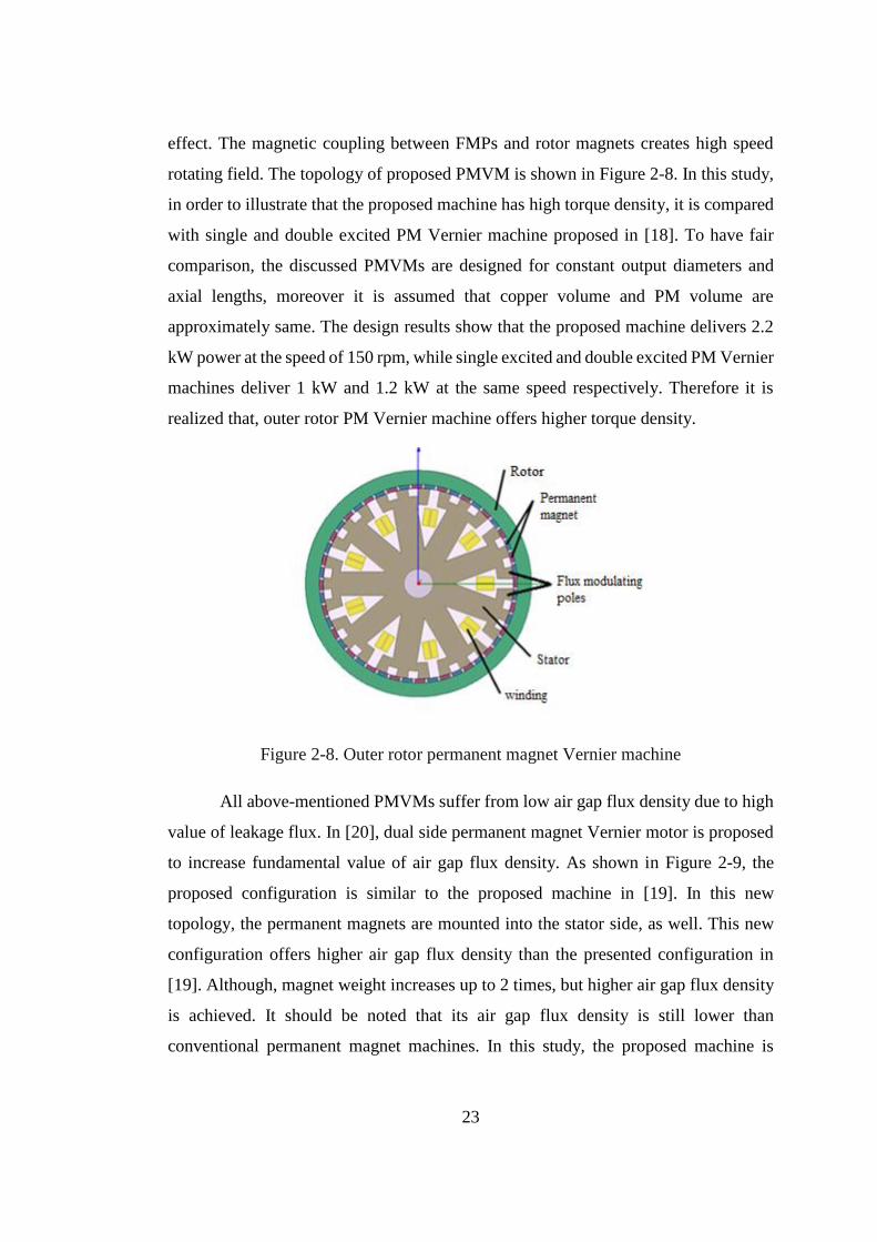
A new outer-rotor PM Vernier machine is proposed, in [19]. This machine has
the advantage of higher torque density compared with proposed single and double
excited PM Vernier machines in [18]. In the new proposed topology, the Flux
Modulation Poles (FMPs) are added to the outer part of the inner stator and PMs are
integrated to the outer rotor. The FMPs play the role of teeth to create magnetic gear
23
effect. The magnetic coupling between FMPs and rotor magnets creates high speed
rotating field. The topology of proposed PMVM is shown in Figure 2-8. In this study,
in order to illustrate that the proposed machine has high torque density, it is compared
with single and double excited PM Vernier machine proposed in [18]. To have fair
comparison, the discussed PMVMs are designed for constant output diameters and
axial lengths, moreover it is assumed that copper volume and PM volume are
approximately same. The design results show that the proposed machine delivers 2.2
kW power at the speed of 150 rpm, while single excited and double excited PM Vernier
machines deliver 1 kW and 1.2 kW at the same speed respectively. Therefore it is
realized that, outer rotor PM Vernier machine offers higher torque density.
Figure 2-8. Outer rotor permanent magnet Vernier machine
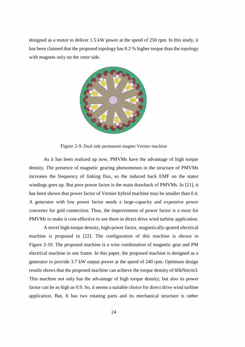
All above-mentioned PMVMs suffer from low air gap flux density due to high
value of leakage flux. In [20], dual side permanent magnet Vernier motor is proposed
to increase fundamental value of air gap flux density. As shown in Figure 2-9, the
proposed configuration is similar to the proposed machine in [19]. In this new
topology, the permanent magnets are mounted into the stator side, as well. This new
configuration offers higher air gap flux density than the presented configuration in
[19]. Although, magnet weight increases up to 2 times, but higher air gap flux density
is achieved. It should be noted that its air gap flux density is still lower than
conventional permanent magnet machines. In this study, the proposed machine is
24
designed as a motor to deliver 1.5 kW power at the speed of 250 rpm. In this study, it
has been claimed that the proposed topology has 8.2 % higher torque than the topology
with magnets only on the rotor side.
Figure 2-9. Dual side permanent magnet Vernier machine
As it has been realized up now, PMVMs have the advantage of high torque
density. The presence of magnetic gearing phenomenon in the structure of PMVMs
increases the frequency of linking flux, so the induced back EMF on the stator
windings goes up. But poor power factor is the main drawback of PMVMs. In [21], it
has been shown that power factor of Vernier hybrid machine may be smaller than 0.4.
A generator with low power factor needs a large-capacity and expensive power
converter for grid connection. Thus, the improvement of power factor is a must for
PMVMs to make it cost-effective to use them in direct drive wind turbine application.
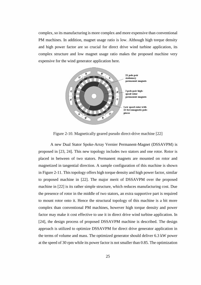
A novel high-torque density, high-power factor, magnetically-geared electrical
machine is proposed in [22]. The configuration of this machine is shown in
Figure 2-10. The proposed machine is a wise combination of magnetic gear and PM
electrical machine in one frame. In this paper, the proposed machine is designed as a
generator to provide 3.7 kW output power at the speed of 240 rpm. Optimum design
results shows that the proposed machine can achieve the torque density of 60kNm/m3.
This machine not only has the advantage of high torque density; but also its power
factor can be as high as 0.9. So, it seems a suitable choice for direct drive wind turbine
application. But, It has two rotating parts and its mechanical structure is rather
25
complex, so its manufacturing is more complex and more expensive than conventional
PM machines. In addition, magnet usage ratio is low. Although high torque density
and high power factor are so crucial for direct drive wind turbine application, its
complex structure and low magnet usage ratio makes the proposed machine very
expensive for the wind generator application here.
Figure 2-10. Magnetically geared pseudo direct-drive machine [22]
A new Dual Stator Spoke-Array Vernier Permanent-Magnet (DSSAVPM) is
proposed in [23, 24]. This new topology includes two stators and one rotor. Rotor is
placed in between of two stators. Permanent magnets are mounted on rotor and
magnetized in tangential direction. A sample configuration of this machine is shown
in Figure 2-11. This topology offers high torque density and high power factor, similar
to proposed machine in [22]. The major merit of DSSAVPM over the proposed
machine in [22] is its rather simple structure, which reduces manufacturing cost. Due
the presence of rotor in the middle of two stators, an extra supportive part is required
to mount rotor onto it. Hence the structural topology of this machine is a bit more
complex than conventional PM machines, however high torque density and power
factor may make it cost effective to use it in direct drive wind turbine application. In
[24], the design process of proposed DSSAVPM machine is described. The design
approach is utilized to optimize DSSAVPM for direct drive generator application in
the terms of volume and mass. The optimized generator should deliver 6.3 kW power
at the speed of 30 rpm while its power factor is not smaller than 0.85. The optimization
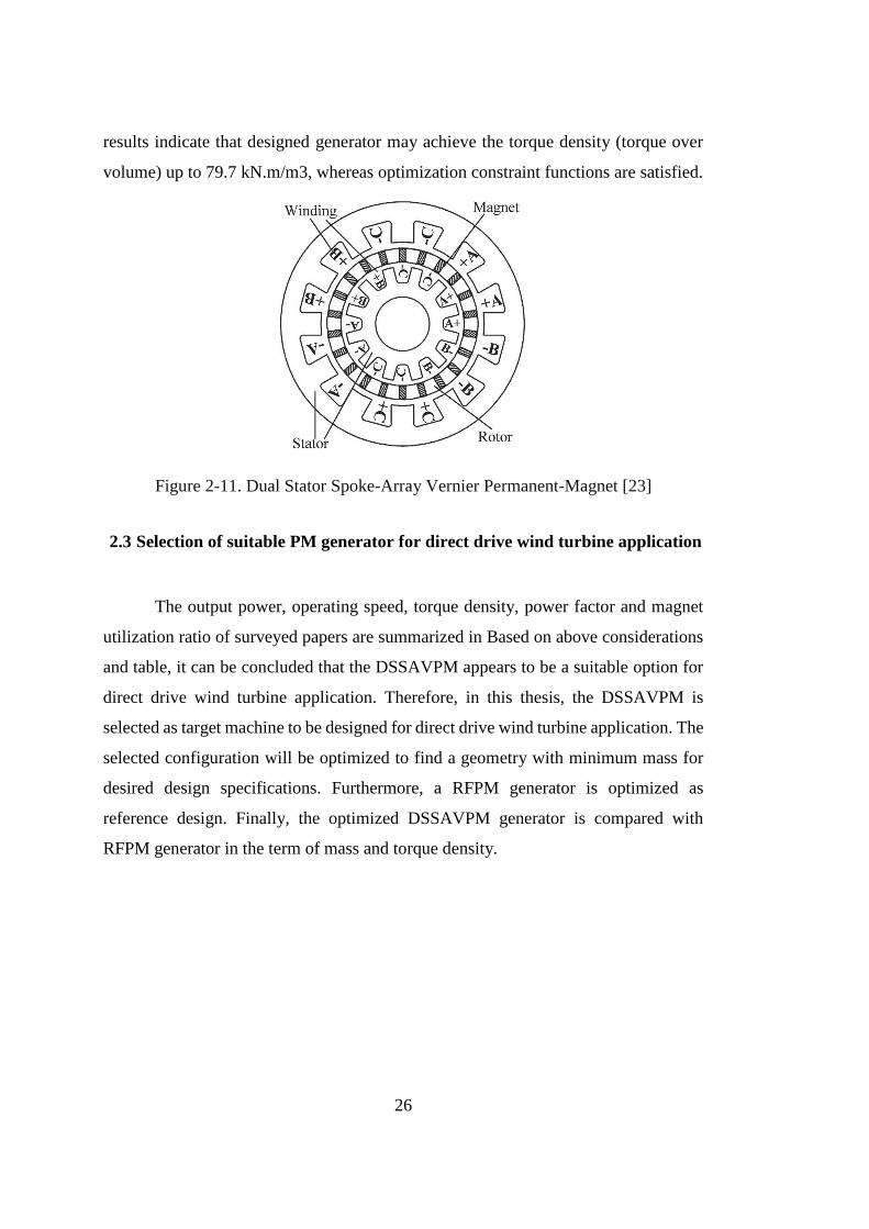
26
results indicate that designed generator may achieve the torque density (torque over
volume) up to 79.7 kN.m/m3, whereas optimization constraint functions are satisfied.
Figure 2-11. Dual Stator Spoke-Array Vernier Permanent-Magnet [23]
2.3 Selection of suitable PM generator for direct drive wind turbine application
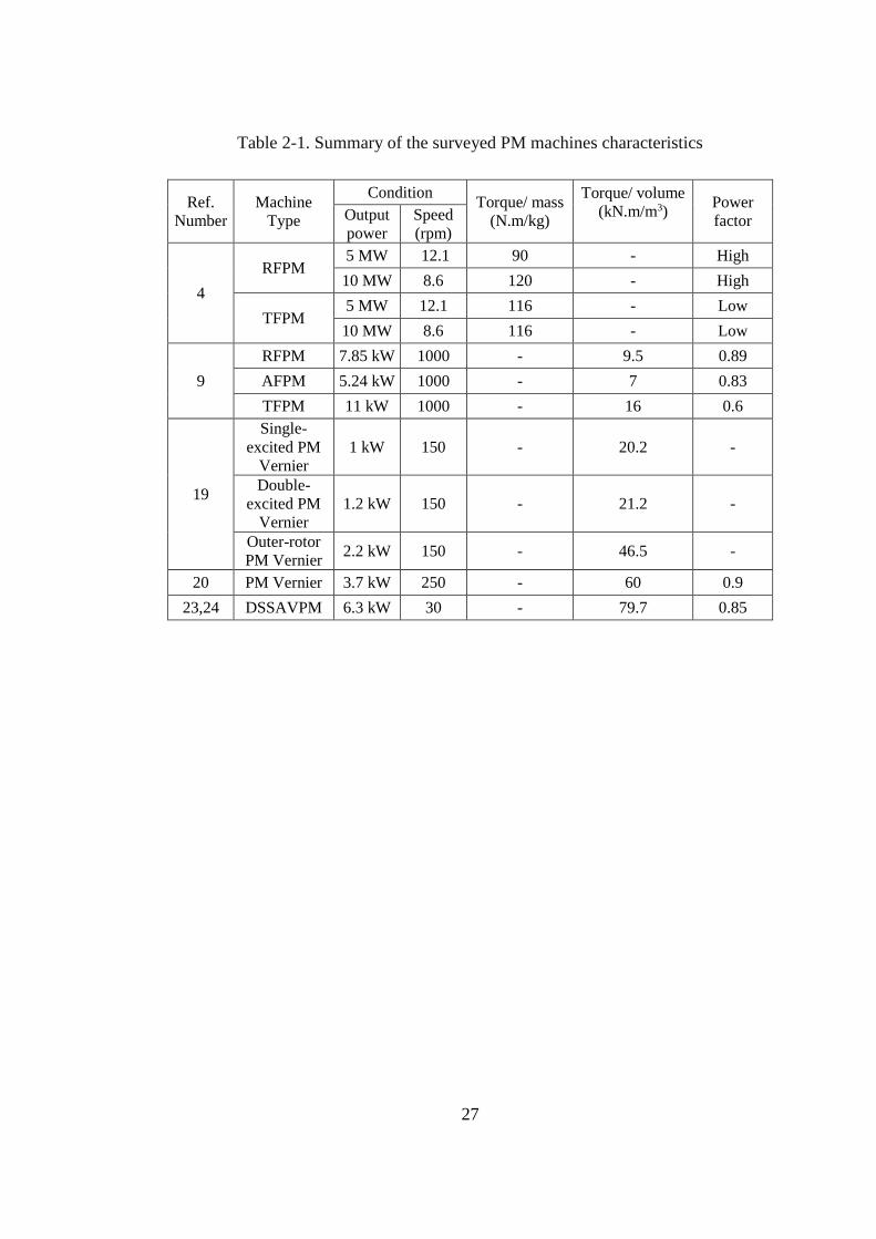
The output power, operating speed, torque density, power factor and magnet
utilization ratio of surveyed papers are summarized in Based on above considerations
and table, it can be concluded that the DSSAVPM appears to be a suitable option for
direct drive wind turbine application. Therefore, in this thesis, the DSSAVPM is
selected as target machine to be designed for direct drive wind turbine application. The
selected configuration will be optimized to find a geometry with minimum mass for
desired design specifications. Furthermore, a RFPM generator is optimized as
reference design. Finally, the optimized DSSAVPM generator is compared with
RFPM generator in the term of mass and torque density.
27
Table 2-1. Summary of the surveyed PM machines characteristics
Ref.
Number
Machine
Type
Condition Torque/ mass
(N.m/kg)
Torque/ volume
(kN.m/m3)
Power
factor Output
power
Speed
(rpm)
4
RFPM 5 MW 12.1 90 - High
10 MW 8.6 120 - High
TFPM 5 MW 12.1 116 - Low
10 MW 8.6 116 - Low
9
RFPM 7.85 kW 1000 - 9.5 0.89
AFPM 5.24 kW 1000 - 7 0.83
TFPM 11 kW 1000 - 16 0.6
19
Single-
excited PM
Vernier
1 kW 150 - 20.2 -
Double-
excited PM
Vernier
1.2 kW 150 - 21.2 -
Outer-rotor
PM Vernier 2.2 kW 150 - 46.5 -
20 PM Vernier 3.7 kW 250 - 60 0.9
23,24 DSSAVPM 6.3 kW 30 - 79.7 0.85

28
29
CHAPTER 3
DESIGN PROCEDURE OF DUAL STATOR SPOKE ARRAY PM VERNIER
GENERATOR
3.1 Introduction
In this chapter, it is aimed to present design process of DSSAVPM generator.
Evaluation of PM machines in previous chapter showed that DSSAVPM generator is
a machine with higher torque density, moreover, in contrast to other PM Vernier
machines and TFPM machines, it does not suffer from low power factor. Therefore,
this machine is chosen to be modelled as direct drive wind turbine generator in this
chapter.
Prior to start design process, it is crucial to know the geometrical structure of
the DSSAVPM machine, so the topology of DSSAVPM machine is explained first.
Then the operating principle of the DSSAVPM machine is described. In order to model
DSSAVPM machine, it is necessary to understand its operation principle. A PM
Vernier machine with rather simple structure is used to explain the operation principle
of these kind of electrical machines and magnetic gear concept.
Following this, the sizing equations are derived and geometrical parameters are
calculated. These equations are utilized in design process of the DSSAVPM generator.
Finally, the performance analysis equations are presented.
3.2 Topology of the DSSAVPM machine
The DSSAVPM machine is composed of two stators and a single rotor
sandwiched between the two stators. The configuration of this machine is shown
Figure 3-1.
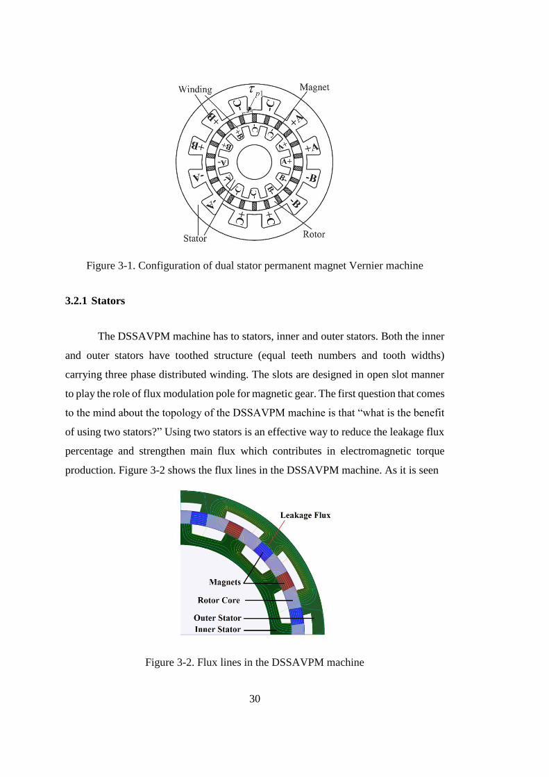
30
Figure 3-1. Configuration of dual stator permanent magnet Vernier machine
3.2.1 Stators
The DSSAVPM machine has to stators, inner and outer stators. Both the inner
and outer stators have toothed structure (equal teeth numbers and tooth widths)
carrying three phase distributed winding. The slots are designed in open slot manner
to play the role of flux modulation pole for magnetic gear. The first question that comes
to the mind about the topology of the DSSAVPM machine is that “what is the benefit
of using two stators?” Using two stators is an effective way to reduce the leakage flux
percentage and strengthen main flux which contributes in electromagnetic torque
production. Figure 3-2 shows the flux lines in the DSSAVPM machine. As it is seen
Figure 3-2. Flux lines in the DSSAVPM machine
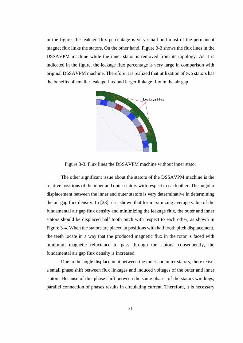
31
in the figure, the leakage flux percentage is very small and most of the permanent
magnet flux links the stators. On the other hand, Figure 3-3 shows the flux lines in the
DSSAVPM machine while the inner stator is removed from its topology. As it is
indicated in the figure, the leakage flux percentage is very large in comparison with
original DSSAVPM machine. Therefore it is realized that utilization of two stators has
the benefits of smaller leakage flux and larger linkage flux in the air gap.
Figure 3-3. Flux lines the DSSAVPM machine without inner stator
The other significant issue about the stators of the DSSAVPM machine is the
relative positions of the inner and outer stators with respect to each other. The angular
displacement between the inner and outer stators is very determinative in determining
the air gap flux density. In [23], it is shown that for maximizing average value of the
fundamental air gap flux density and minimizing the leakage flux, the outer and inner
stators should be displaced half tooth pitch with respect to each other, as shown in
Figure 3-4. When the stators are placed in positions with half tooth pitch displacement,
the teeth locate in a way that the produced magnetic flux in the rotor is faced with
minimum magnetic reluctance to pass through the stators, consequently, the
fundamental air gap flux density is increased.
Due to the angle displacement between the inner and outer stators, there exists
a small phase shift between flux linkages and induced voltages of the outer and inner
stators. Because of this phase shift between the same phases of the stators windings,
parallel connection of phases results in circulating current. Therefore, it is necessary
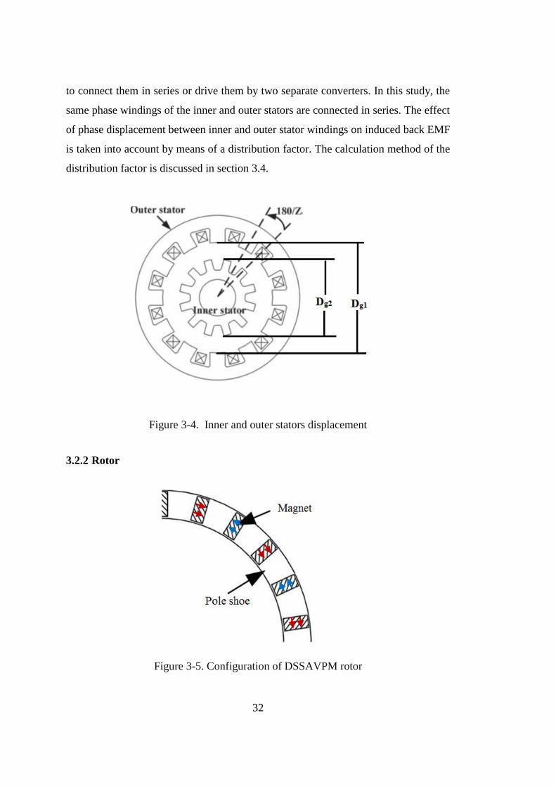
32
to connect them in series or drive them by two separate converters. In this study, the
same phase windings of the inner and outer stators are connected in series. The effect
of phase displacement between inner and outer stator windings on induced back EMF
is taken into account by means of a distribution factor. The calculation method of the
distribution factor is discussed in section 3.4.
Figure 3-4. Inner and outer stators displacement
3.2.2 Rotor
Figure 3-5. Configuration of DSSAVPM rotor
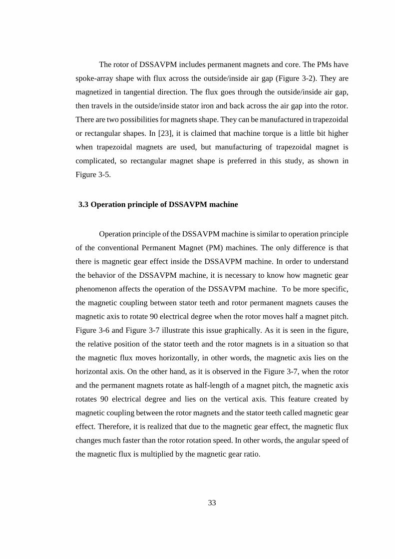
33
The rotor of DSSAVPM includes permanent magnets and core. The PMs have
spoke-array shape with flux across the outside/inside air gap (Figure 3-2). They are
magnetized in tangential direction. The flux goes through the outside/inside air gap,
then travels in the outside/inside stator iron and back across the air gap into the rotor.
There are two possibilities for magnets shape. They can be manufactured in trapezoidal
or rectangular shapes. In [23], it is claimed that machine torque is a little bit higher
when trapezoidal magnets are used, but manufacturing of trapezoidal magnet is
complicated, so rectangular magnet shape is preferred in this study, as shown in
Figure 3-5.
3.3 Operation principle of DSSAVPM machine
Operation principle of the DSSAVPM machine is similar to operation principle
of the conventional Permanent Magnet (PM) machines. The only difference is that
there is magnetic gear effect inside the DSSAVPM machine. In order to understand
the behavior of the DSSAVPM machine, it is necessary to know how magnetic gear
phenomenon affects the operation of the DSSAVPM machine. To be more specific,
the magnetic coupling between stator teeth and rotor permanent magnets causes the
magnetic axis to rotate 90 electrical degree when the rotor moves half a magnet pitch.
Figure 3-6 and Figure 3-7 illustrate this issue graphically. As it is seen in the figure,
the relative position of the stator teeth and the rotor magnets is in a situation so that
the magnetic flux moves horizontally, in other words, the magnetic axis lies on the
horizontal axis. On the other hand, as it is observed in the Figure 3-7, when the rotor
and the permanent magnets rotate as half-length of a magnet pitch, the magnetic axis
rotates 90 electrical degree and lies on the vertical axis. This feature created by
magnetic coupling between the rotor magnets and the stator teeth called magnetic gear
effect. Therefore, it is realized that due to the magnetic gear effect, the magnetic flux
changes much faster than the rotor rotation speed. In other words, the angular speed of
the magnetic flux is multiplied by the magnetic gear ratio.
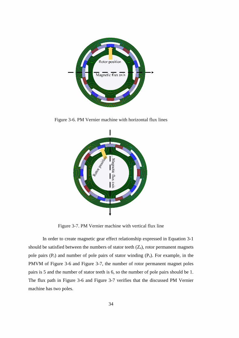
34
Figure 3-6. PM Vernier machine with horizontal flux lines
Figure 3-7. PM Vernier machine with vertical flux line
In order to create magnetic gear effect relationship expressed in Equation 3-1
should be satisfied between the numbers of stator teeth (Zs), rotor permanent magnets
pole pairs (Pr) and number of pole pairs of stator winding (Ps). For example, in the
PMVM of Figure 3-6 and Figure 3-7, the number of rotor permanent magnet poles
pairs is 5 and the number of stator teeth is 6, so the number of pole pairs should be 1.
The flux path in Figure 3-6 and Figure 3-7 verifies that the discussed PM Vernier
machine has two poles.
35
r s sP Z P (3-1)
According to the Equation, there are two choices for Pr value, when Zs and Ps
are known. In [18], it is analytically shown that the choice of minus sign (-) in Equation
(3-1 provides higher air gap flux density and subsequently higher torque than plus sign
(+). Therefore, the choice of Pr should be Zs-Ps to obtain higher torque for the same
dimensions.
The magnetic gear ratio of a PMVM machine with Pr permanent magnet pairs
on the rotor and Ps pole pairs is expressed in the Equation 3-2. The frequency of linking
flux in a conventional PM machine and a PMVM machine are expressed in
Equations 3-3 and 3-4 respectively. According to the Equation 3-3, linking flux
frequency in a conventional PM machine is proportional to shaft speed and number of
pole pairs (Ps), while it is not the case for PMVMs. In a PMVM machine the linking
flux frequency is proportional to the shaft speed and the rotor pole pairs (Pr). In other
words, due to the magnetic gear effect, the frequency of linking flux is multiplied by
magnetic gear ratio (GR) and the magnetic flux rotates GR times faster than
conventional PM machines flux with the same number of poles.
r
s
PGR
P (3-2)
2
120
sConventional
n Pf
(3-3)
2
120 60
s rVernier
n P n Pf GR
(3-4)
As it was mentioned previously, PMVMs operate in a manner similar to the
conventional PM Synchronous Machines (PMSM). The only difference is that they
have magnetic gear in their structure to increase linking flux frequency. Therefore, the
equation of induced back EMF in PMSM is valid for PMVMs and can be expressed
using Equation 3-5.
4.44a w ph Vernier avg pE k N f B A (3-5)
where, Nph, fVernier, Bavg and Ap are number of turns per phase, linking flux frequency,
average value of fundamental air gap flux density and area under a pole, respectively.
36
As it is seen in the Equation 3-5, induced EMF is proportional to the frequency of
linking flux. As frequency goes up, induced back EMF is increased. Hence, it can be
stated that magnetic gear effect brings a great advantage for PMVMs. Because it
increases the frequency of linking flux and consequently induced back EMF becomes
larger.
Although presence of magnetic gear offers a great merit for PMVMs and
increases the frequency of linking flux, on the other hand it also imposes a drawback
to the PMVMs. In general, PMVMs have lower air gap flux density compared with
conventional PM machines. Due to the higher number of permanent magnets and
magnetic coupling between teeth and permanent magnets, leakage flux (see
Figure 3-2) percentage is higher, and fundamental value of the air gap flux density is
lower compared with conventional PM machines. According to the Equation 3-5,
induced back EMF is also proportional to the average value of the air gap flux density
(Bavg). Low value of Bavg in PMVM affects induced EMF negatively, but magnetic
gearing compensates the adverse effect of low Bavg.
The main focus of this chapter is to present a detailed design procedure of the
DSSAVPM including sizing equations, geometrical design and performance
parameters calculation. In the first step, sizing equation is derived in the terms of
generator torque. Main dimensions including, bore diameter and axial length, are
calculated using this equation. Then geometrical dimensions including, teeth height,
back-core length and teeth width are derived in the terms of main dimensions. Finally,
performance analysis is presented to be able evaluate the performance of the designed
generator.
In contrast to the conventional PM machines, it is a rather difficult task to
calculate fundamental value of air gap flux density using analytic equations in
PMVMs. Complex magnetic circuit and high percentage of leakage flux make it
difficult to separate fundamental value of the air gap flux from its harmonic content.
Therefore, Finite Element Method (FEM) is utilized to analysis magnetic circuit and
obtain fundamental value of the air gap flux density. The design procedure is explained
in the following sections.
37
3.4 Sizing equation of DSSAVPM
The first step in the design procedure of the DSSAVPM generator is the
derivation of sizing equation. This equation relates the generator torque to the main
dimensions, electric loading and magnetic loading of the generator. In the design stage,
it is reasonable to assume that machine efficiency is unity, therefore electromagnetic
power will be equal to input power. Since the operation principle of DSSAVPM
machine is similar to the synchronous machines, electromagnetic power can be
expressed as,
3 cos( )e a aP E I (3-6)
Where Ea and Ia are RMS values of fundamental phase EMF and phase current
respectively, and γ is the phase displacement between the EMF and current vectors. In
this study, it assumed that γ angle is zero and back-EMF and phase current are aligned.
This is a reasonable assumption, since it is possible to control γ by means of the
converter connecting the generator to the power grid, so cosine term is eliminated from
the power equation.
Since the operation principle of DSSAVPM is similar to the conventional PM
machines, back-EMF calculation method is the same, however it should be noted that
there are two windings for each phase, the inner stator and the outer stator windings.
The outer and inner windings are connected in series, so induced back-EMF of a phase
is the summation of beck-EMFs in the both outer and inner windings. It is worth to
mention that the effect of phase shift between outer and inner windings back-EMFs
will be considered in winding factor (kw). Thus, induced back-EMF of a phase can be
expressed as follows,
2a w Vernier ph in avg in p in ph out avg out p outE k f N B A N B A (3-7)
Where Nph-in and Nph-out are number of turns per phase for inner and outer
windings. Bavg-in and Bavg-out are average value of fundamental flux density in the inner
and outer air gap. Ap-in and Ap-out are the pole areas expressed as follows,
2
2
g stk
p in
s
D LA
P
(3-8)
38
1
2
g stk
p out
s
D LA
P
(3-9)
Where Dg1 and Dg2 are bore diameters of outer and inner stator, see Figure 3-8
and Figure 3-10. Lstk is axial length of the machine. Using above equation the
electromagnetic power is obtained as follows,
3 260
re w a ph in avg in p in ph out avg out p out
n PP k I N B A N B A
(3-10)
So, the electromagnetic torque can be obtained by dividing the power equation
with synchronous speed and can be expressed as,
3 2
2e w r a ph in avg in p in ph out avg out p outT k P I N B A N B A (3-11)
In general, it is preferred to express the torque equation in the terms of electric
loading instead of phase current. The electrical loading for inner and outer stator
windings are defined as follows
2
3 2 ph in a
in
g
N Iq
D
(3-12)
1
3 2 ph out a
out
g
N Iq
D
(3-13)
By combining of Equations 3-11, 3-12 and 3-13, electromagnetic torque is
obtained as follows.
2 2 2
2 1
2
8e w stk in avg in g out avg out gT k GR L q B D q B D (3-14)
If friction and windage losses are neglected, the electromagnetic torque (Te)
and output torque (Tout) will be identical.
Winding factor (kw) is the product of distribution factor (kd) and pitch factor
(kp).
w p dk k k (3-15)
Based on previous discussion, the effect of phase shift between outer and inner
stators on back-EMF is taken into account via distribution factor. So, distribution
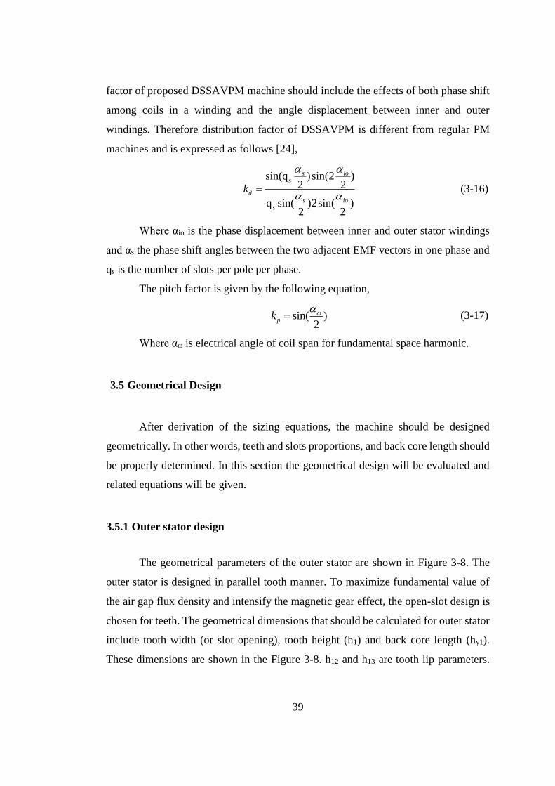
39
factor of proposed DSSAVPM machine should include the effects of both phase shift
among coils in a winding and the angle displacement between inner and outer
windings. Therefore distribution factor of DSSAVPM is different from regular PM
machines and is expressed as follows [24],
sin(q )sin(2 )2 2
q sin( )2sin( )2 2
s ios
ds io
s
k
(3-16)
Where αio is the phase displacement between inner and outer stator windings
and αs the phase shift angles between the two adjacent EMF vectors in one phase and
qs is the number of slots per pole per phase.
The pitch factor is given by the following equation,
sin( )2
pk (3-17)
Where αω is electrical angle of coil span for fundamental space harmonic.
3.5 Geometrical Design
After derivation of the sizing equations, the machine should be designed
geometrically. In other words, teeth and slots proportions, and back core length should
be properly determined. In this section the geometrical design will be evaluated and
related equations will be given.
3.5.1 Outer stator design
The geometrical parameters of the outer stator are shown in Figure 3-8. The
outer stator is designed in parallel tooth manner. To maximize fundamental value of
the air gap flux density and intensify the magnetic gear effect, the open-slot design is
chosen for teeth. The geometrical dimensions that should be calculated for outer stator
include tooth width (or slot opening), tooth height (h1) and back core length (hy1).
These dimensions are shown in the Figure 3-8. h12 and h13 are tooth lip parameters.
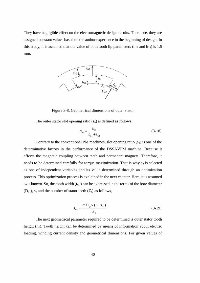
40
They have negligible effect on the electromagnetic design results. Therefore, they are
assigned constant values based on the author experience in the beginning of design. In
this study, it is assumed that the value of both tooth lip parameters (h12 and h13) is 1.5
mm.
Figure 3-8. Geometrical dimensions of outer stator
The outer stator slot opening ratio (so) is defined as follows,
11
1 1
oo
o w
bs
b t
(3-18)
Contrary to the conventional PM machines, slot opening ratio (so) is one of the
determinative factors in the performance of the DSSAVPM machine. Because it
affects the magnetic coupling between teeth and permanent magnets. Therefore, it
needs to be determined carefully for torque maximization. That is why so is selected
as one of independent variables and its value determined through an optimization
process. This optimization process is explained in the next chapter. Here, it is assumed
so is known. So, the tooth width (tw1) can be expressed in the terms of the bore diameter
(Dg1), so and the number of stator teeth (Zs) as follows,
1 1
1
D (1 s )g o
w
s
tZ
(3-19)
The next geometrical parameter required to be determined is outer stator tooth
height (h1). Tooth height can be determined by means of information about electric
loading, winding current density and geometrical dimensions. For given values of
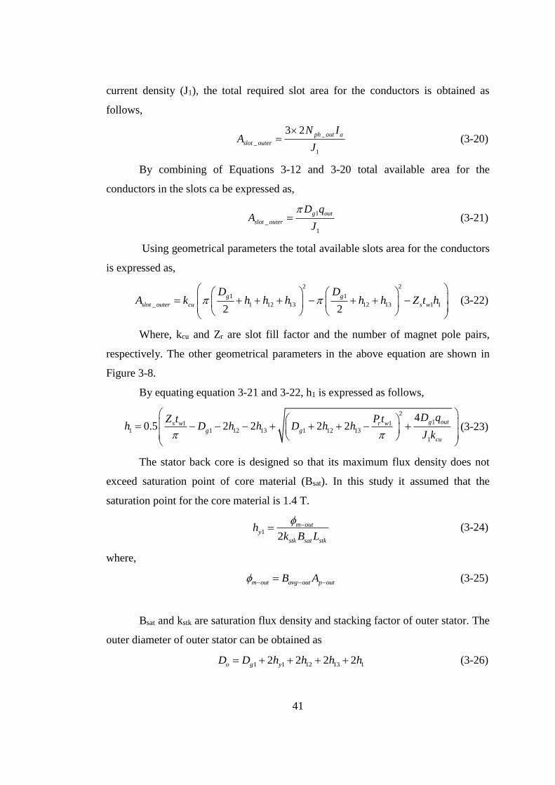
41
current density (J1), the total required slot area for the conductors is obtained as
follows,
_
_
1
3 2 ph out a
slot outer
N IA
J
(3-20)
By combining of Equations 3-12 and 3-20 total available area for the
conductors in the slots ca be expressed as,
1
_
1
g out
slot outer
D qA
J
(3-21)
Using geometrical parameters the total available slots area for the conductors
is expressed as,
2 2
1 1
_ 1 12 13 12 13 1 12 2
g g
slot outer cu s w
D DA k h h h h h Z t h
(3-22)
Where, kcu and Zr are slot fill factor and the number of magnet pole pairs,
respectively. The other geometrical parameters in the above equation are shown in
Figure 3-8.
By equating equation 3-21 and 3-22, h1 is expressed as follows,
2
11 11 1 12 13 1 12 13
1
40.5 2 2 2 2
g outs w r wg g
cu
D qZ t P th D h h D h h
J k
(3-23)
The stator back core is designed so that its maximum flux density does not
exceed saturation point of core material (Bsat). In this study it assumed that the
saturation point for the core material is 1.4 T.
1
2
m outy
stk sat stk
hk B L
(3-24)
where,
m out avg out p outB A (3-25)
Bsat and kstk are saturation flux density and stacking factor of outer stator. The
outer diameter of outer stator can be obtained as
1 1 12 13 12 2 2 2o g yD D h h h h (3-26)
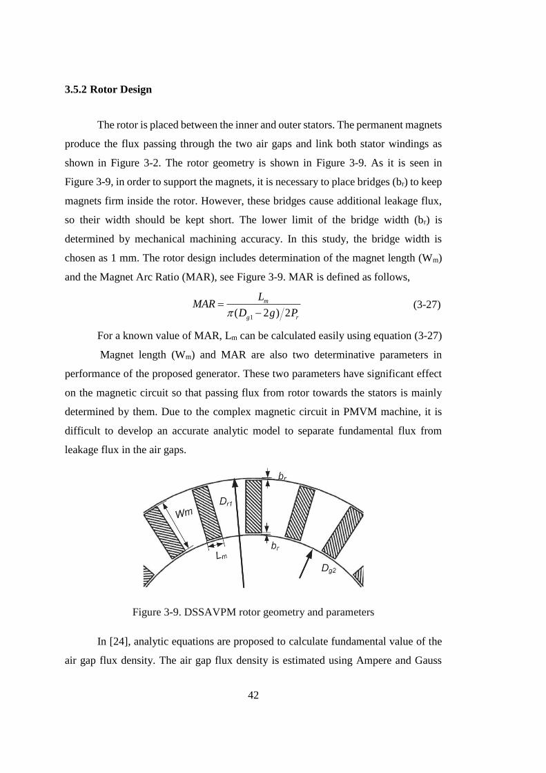
42
3.5.2 Rotor Design
The rotor is placed between the inner and outer stators. The permanent magnets
produce the flux passing through the two air gaps and link both stator windings as
shown in Figure 3-2. The rotor geometry is shown in Figure 3-9. As it is seen in
Figure 3-9, in order to support the magnets, it is necessary to place bridges (br) to keep
magnets firm inside the rotor. However, these bridges cause additional leakage flux,
so their width should be kept short. The lower limit of the bridge width (br) is
determined by mechanical machining accuracy. In this study, the bridge width is
chosen as 1 mm. The rotor design includes determination of the magnet length (Wm)
and the Magnet Arc Ratio (MAR), see Figure 3-9. MAR is defined as follows,
1( 2 ) 2
m
g r
LMAR
D g P
(3-27)
For a known value of MAR, Lm can be calculated easily using equation (3-27)
Magnet length (Wm) and MAR are also two determinative parameters in
performance of the proposed generator. These two parameters have significant effect
on the magnetic circuit so that passing flux from rotor towards the stators is mainly
determined by them. Due to the complex magnetic circuit in PMVM machine, it is
difficult to develop an accurate analytic model to separate fundamental flux from
leakage flux in the air gaps.
Figure 3-9. DSSAVPM rotor geometry and parameters
In [24], analytic equations are proposed to calculate fundamental value of the
air gap flux density. The air gap flux density is estimated using Ampere and Gauss
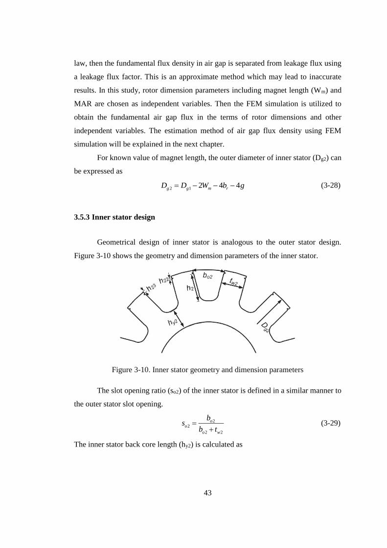
43
law, then the fundamental flux density in air gap is separated from leakage flux using
a leakage flux factor. This is an approximate method which may lead to inaccurate
results. In this study, rotor dimension parameters including magnet length (Wm) and
MAR are chosen as independent variables. Then the FEM simulation is utilized to
obtain the fundamental air gap flux in the terms of rotor dimensions and other
independent variables. The estimation method of air gap flux density using FEM
simulation will be explained in the next chapter.
For known value of magnet length, the outer diameter of inner stator (Dg2) can
be expressed as
2 1 2 4 4g g m rD D W b g (3-28)
3.5.3 Inner stator design
Geometrical design of inner stator is analogous to the outer stator design.
Figure 3-10 shows the geometry and dimension parameters of the inner stator.
Figure 3-10. Inner stator geometry and dimension parameters
The slot opening ratio (so2) of the inner stator is defined in a similar manner to
the outer stator slot opening.
22
2 2
oo
o w
bs
b t
(3-29)
The inner stator back core length (hy2) is calculated as
44
2
2
m iny
stk sat stk
hk B L
(3-30)
where,
m in avg in p inB A (3-31)
For a known value of slot opening, inner stator tooth width (tw2) is expressed
as follows,
2
2
D (1 s )g o
w
s
tZ
(3-32)
Based on same method as the outer stator does, the inner stator teeth depth can
be obtained.
2
_
2
g in
slot inner
cu
D qA
J k
(3-33)
2
2 2 22 2 22 23 2 22 23
2
40.5 2 2 2 2r w r w in
g g
cu
P t P t D qh D h h D h h
J k
(3-34)
Therefore, inner diameter of inner stator is expressed as,
2 2 22 23 22 2 2 2i g yD D h h h h (3-35)
3.6 Calculation of phase Turns, resistance and inductance
3.6.1 Turns per phase
Number of turns per phase for inner and outer stators windings can obtained
using Equations 3-12 and 3-13 , for a specified values of electric loadings.
2
3 2
in g
ph in
a
q DN
I
(3-36)
1
3 2
out g
ph out
a
q DN
I
(3-37)
Where Ia is the rated phase current.
45
Since inner and outer stators windings are in series, so total phase turn number
is obtained by,
ph ph in ph outN N N (3-38)
3.6.2 Phase resistance
Phase resistance is determined based on Mean Length of a Turn (MLT), wire
cross section area and copper resistivity and expressed as follows,
ph
ph cu
conductor
N MLTR P
A
(3-39)
Where, Pcu, MLT and Awire are copper resistivity, mean length of a turn and
area of one conductor. MLT of outer and inner stators windings are calculated using
following equations,
1 12 13 1
2 22 23 2
(D 2h 2h h )2(L 2L )
2
(D 2h 2h h )2(L 2L )
2
g
outer stk end
s
g
inner stk end
s
MLTp
MLTp
(3-40)
conductor cross sectional area for the outer and inner stators windings are
expressed as follows,
_
_inner
slot outer cucoduct outer
slot outer
slot inner cucoduct
slot inner
A kA
N
A kA
N
(3-41)
Where,
3 2
3 2
ph outer
slot outer
s
ph inner
slot inner
s
NN
Z
NN
Z
(3-42)
The total phase resistance is the summation of outer and inner stators phase
resistances.
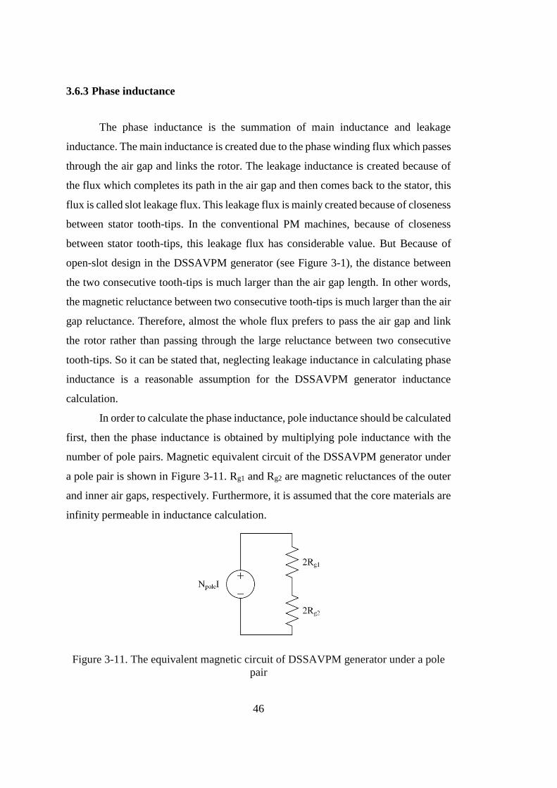
46
3.6.3 Phase inductance
The phase inductance is the summation of main inductance and leakage
inductance. The main inductance is created due to the phase winding flux which passes
through the air gap and links the rotor. The leakage inductance is created because of
the flux which completes its path in the air gap and then comes back to the stator, this
flux is called slot leakage flux. This leakage flux is mainly created because of closeness
between stator tooth-tips. In the conventional PM machines, because of closeness
between stator tooth-tips, this leakage flux has considerable value. But Because of
open-slot design in the DSSAVPM generator (see Figure 3-1), the distance between
the two consecutive tooth-tips is much larger than the air gap length. In other words,
the magnetic reluctance between two consecutive tooth-tips is much larger than the air
gap reluctance. Therefore, almost the whole flux prefers to pass the air gap and link
the rotor rather than passing through the large reluctance between two consecutive
tooth-tips. So it can be stated that, neglecting leakage inductance in calculating phase
inductance is a reasonable assumption for the DSSAVPM generator inductance
calculation.
In order to calculate the phase inductance, pole inductance should be calculated
first, then the phase inductance is obtained by multiplying pole inductance with the
number of pole pairs. Magnetic equivalent circuit of the DSSAVPM generator under
a pole pair is shown in Figure 3-11. Rg1 and Rg2 are magnetic reluctances of the outer
and inner air gaps, respectively. Furthermore, it is assumed that the core materials are
infinity permeable in inductance calculation.
Figure 3-11. The equivalent magnetic circuit of DSSAVPM generator under a pole
pair
47
The air gaps reluctances are expressed as follows.
1
0
2
0
e outg
p out
e ing
p in
gR
A
gR
A
(3-43)
Where, µ0 is the air permeability coefficient. ge1 and ge2 are effective lengths
of outer and inner air gaps. The calculation method of effective air gaps lengths is
explained in the next subsection.
The phase inductance can be expressed using Equation 3-44. This equation
gives the total inductance of phase (sum of the inner and outer stators inductance).
2
1 22
w p
ph s
g g
k NL P
R R
(3-44)
Where, Np is the number of turns per phase per pole, which can be expressed
as follows,
ph
p
s
NN
P (3-45)
3.6.3.1 Calculation method of the effective air gap length
The air gap length is a critical factor in calculation of phase inductance. In order
to consider the impact of slots, effective air gap length should be used in inductance
estimation. Carter coefficient is utilized to calculate effective air gap length both for
inner and outer air gaps. This coefficient is obtained with respect to the slots
dimensions and air gap length. The relative permeability of Permanent Magnet (PM)
materials is close to 1, so the rotor magnets show the property of air for winding flux,
consequently rotor PMs behave as slots and rotor pole arcs behave as teeth. Therefore,
double sided Carter model can be utilized to obtain effective lengths for inner and outer
air gaps.
In [25], an improved Carter method is proposed. In this method, air gap
coefficient is calculated as follows.
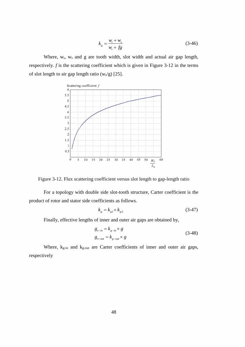
48
t sg
t
w wk
w fg
(3-46)
Where, wt, ws and g are tooth width, slot width and actual air gap length,
respectively. f is the scattering coefficient which is given in Figure 3-12 in the terms
of slot length to air gap length ratio (ws/g) [25].
Figure 3-12. Flux scattering coefficient versus slot length to gap-length ratio
For a topology with double side slot-tooth structure, Carter coefficient is the
product of rotor and stator side coefficients as follows.
1 2g g gk k k (3-47)
Finally, effective lengths of inner and outer air gaps are obtained by,
e in g in
e out g out
g k g
g k g
(3-48)
Where, kg-in and kg-out are Carter coefficients of inner and outer air gaps,
respectively
49
3.7 Volume and mass calculations
In order to obtain total mass of the designed machine, it is necessary to
calculate the volume of the iron, copper and magnet parts based on calculated
dimensions as described in the previous sections. In this section, the calculation
method of volume of the iron, copper and magnet parts will be shown.
3.7.1 Copper volume
Copper volume is calculated in the terms of conductor length and cross
sectional area as follows,
cu ph out outer conduct outer ph in inner conduct innerV N MLT A N MLT A (3-49)
3.7.2 Magnet volume
Magnet volume is calculated in the terms of magnet width (Wm) and Magnet
Arc Ratio (MAR),
1( 2 )mag g m stkV D g MAR W L (3-50)
3.7.3 Iron volume
Iron parts volume includes the rotor, the inner and outer stators volumes. Rotor
volume is obtained by means of following equation,
2 2
1 2[(D 2 ) (D 2 ) ]
4
g g
rotor mag
g gV V
(3-51)
The outer and inner stators volume is expressed as follows,
2 2
1
1 1 12 13
(D (D 2h ) )(h h h )
4
o o y
outer stator s wV Z t
(3-52)
2 2
2
2 2 22 23
((D 2h ) D )(h h h )
4
i y i
inner stator s wV Z t
(3-53)
50
3.7.4 Total mass
Finally, total mass is expressed in the terms of material volume and mass
density (d) as follows,
cu cu mag mag iron rotor iron statorMass d V d V d V d V (3-54)
where dcu, dmag and diron are mass density of copper, permanent magnet and core iron
respectively.
3.8 Loss calculations
Copper loss and core losses are two main losses components in electrical
machines. Other losses such as permanent magnet loss are neglected in this study. In
this section, the analytic calculation method of loss components is presented.
3.8.1 Copper losses
Phase resistances of inner and outer stators are calculated in the terms of
generator geometry in previous sections. Therefore, resistive loss can be calculated for
rated current as follows,
23(R R )copper ph inner ph outer aP I (3-55)
3.8.2 Core losses
Similar to the conventional PM machines, the stators of DSSAVPM machine
sense magnetic flux variation, so hysteresis and eddy current losses are created in the
stators core. The core losses are proportional to core peak flux density, its frequency
and core material core loss characteristic. In this study, only the fundamental
component of the core flux density is taken into account in core loss calculation and
its harmonic content is neglected. The frequency of fundamental flux density in the
stators core can be obtained using Equation 3-4. The peak value of fundamental flux
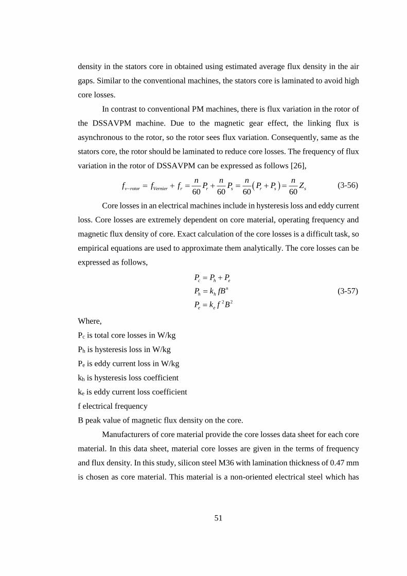
51
density in the stators core in obtained using estimated average flux density in the air
gaps. Similar to the conventional machines, the stators core is laminated to avoid high
core losses.
In contrast to conventional PM machines, there is flux variation in the rotor of
the DSSAVPM machine. Due to the magnetic gear effect, the linking flux is
asynchronous to the rotor, so the rotor sees flux variation. Consequently, same as the
stators core, the rotor should be laminated to reduce core losses. The frequency of flux
variation in the rotor of DSSAVPM can be expressed as follows [26],
60 60 60 60
v rotor Vernier r r s r s s
n n n nf f f P P P P Z (3-56)
Core losses in an electrical machines include in hysteresis loss and eddy current
loss. Core losses are extremely dependent on core material, operating frequency and
magnetic flux density of core. Exact calculation of the core losses is a difficult task, so
empirical equations are used to approximate them analytically. The core losses can be
expressed as follows,
2 2
c h e
n
h h
e e
P P P
P k fB
P k f B
(3-57)
Where,
Pc is total core losses in W/kg
Ph is hysteresis loss in W/kg
Pe is eddy current loss in W/kg
kh is hysteresis loss coefficient
ke is eddy current loss coefficient
f electrical frequency
B peak value of magnetic flux density on the core.
Manufacturers of core material provide the core losses data sheet for each core
material. In this data sheet, material core losses are given in the terms of frequency
and flux density. In this study, silicon steel M36 with lamination thickness of 0.47 mm
is chosen as core material. This material is a non-oriented electrical steel which has
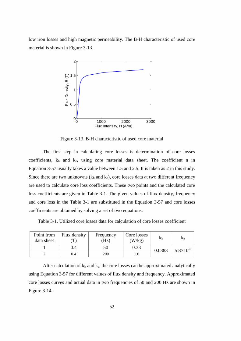
52
low iron losses and high magnetic permeability. The B-H characteristic of used core
material is shown in Figure 3-13.
Figure 3-13. B-H characteristic of used core material
The first step in calculating core losses is determination of core losses
coefficients, kh and ke, using core material data sheet. The coefficient n in
Equation 3-57 usually takes a value between 1.5 and 2.5. It is taken as 2 in this study.
Since there are two unknowns (kh and ke), core losses data at two different frequency
are used to calculate core loss coefficients. These two points and the calculated core
loss coefficients are given in Table 3-1. The given values of flux density, frequency
and core loss in the Table 3-1 are substituted in the Equation 3-57 and core losses
coefficients are obtained by solving a set of two equations.
Table 3-1. Utilized core losses data for calculation of core losses coefficient
Point from
data sheet
Flux density
(T)
Frequency
(Hz)
Core losses
(W/kg) kh ke
1 0.4 50 0.33 0.0383 5.8×10⁻⁵
2 0.4 200 1.6
After calculation of kh and ke, the core losses can be approximated analytically
using Equation 3-57 for different values of flux density and frequency. Approximated
core losses curves and actual data in two frequencies of 50 and 200 Hz are shown in
Figure 3-14.
0 1000 2000 30000
0.5
1
1.5
2
Flux Intensity, H (A/m)
Flu
x D
en
sity
, B
(T
)
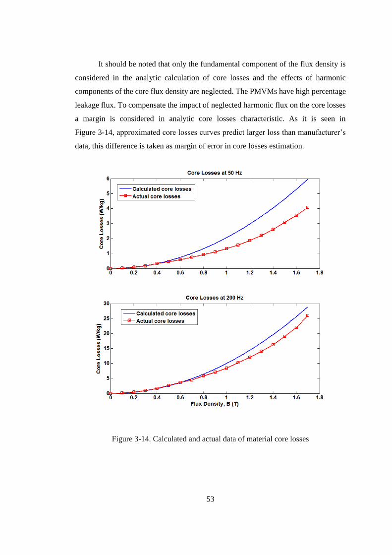
53
It should be noted that only the fundamental component of the flux density is
considered in the analytic calculation of core losses and the effects of harmonic
components of the core flux density are neglected. The PMVMs have high percentage
leakage flux. To compensate the impact of neglected harmonic flux on the core losses
a margin is considered in analytic core losses characteristic. As it is seen in
Figure 3-14, approximated core losses curves predict larger loss than manufacturer’s
data, this difference is taken as margin of error in core losses estimation.
Figure 3-14. Calculated and actual data of material core losses
54
3.8.2.1 Inner and outer stators core losses
Similar to the conventional PM machines, due to flux variation in the both
stators of the DSSAVPM generator, core losses is created. The stators core losses
include in losses at stators teeth and stators back-cores. In order to calculate core losses
at each part, it is required to obtain peak value of flux density in each part. According
to the Equations 3-24 and 3-30, the two stators back-cores are calculated in a way that
their maximum flux density is limited to Bsat, thus back-cores peak flux densities is
Bsat. As it was mentioned before, the value of Bsat is chosen as 1.4 T in this study.
The maximum value of flux density on stator teeth can be calculated using
average value of air gap fundamental flux density. If it is assumed that slot opening
ratio (so) is known, average and peak values of tooth flux density for inner and outer
stators is expressed as follows,
1
1
avg in
avg tooth in
o
avg out
avg tooth out
o
BB
s
BB
s
(3-58)
2
2
peak tooth in avg tooth in
peak tooth out avg tooth out
B B
B B
(3-59)
Now, core losses per unit of mass can be calculated using Equation 3-57 for
the stators back-cores and teeth. In order to obtain total the core losses, the calculated
core losses per unit of mass should be multiplied by the mass of each part. The back-
cores and teeth masses are expressed as follows,
2 2
1
2 2
2
(D (D 2h ) )
4
((D 2h ) D )
4
o o y
bc out iron
i y i
bc in iron
M d
M d
(3-60)
1 1 12 13
2 2 22 23
(h h h )
(h h h )
teeth out s w
teeth in s w
M Z t
M Z t
(3-61)
Stators core losses can be expressed as,
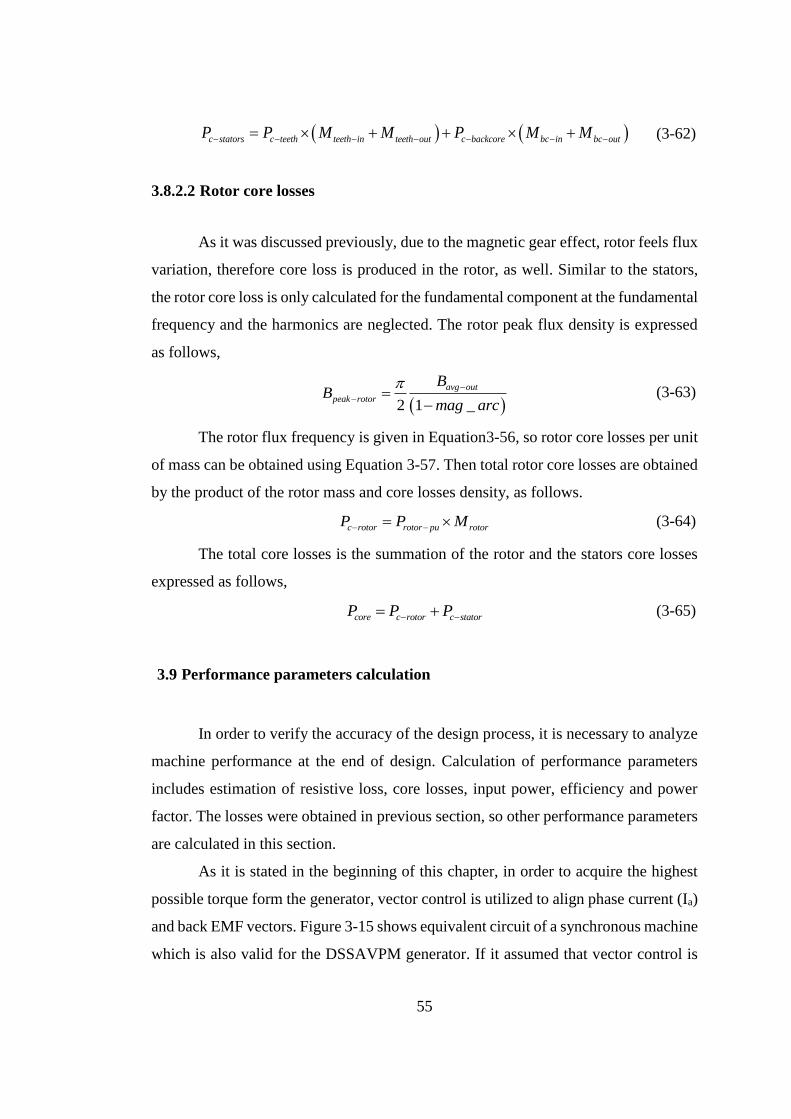
55
c stators c teeth teeth in teeth out c backcore bc in bc outP P M M P M M (3-62)
3.8.2.2 Rotor core losses
As it was discussed previously, due to the magnetic gear effect, rotor feels flux
variation, therefore core loss is produced in the rotor, as well. Similar to the stators,
the rotor core loss is only calculated for the fundamental component at the fundamental
frequency and the harmonics are neglected. The rotor peak flux density is expressed
as follows,
2 1 _
avg out
peak rotor
BB
mag arc
(3-63)
The rotor flux frequency is given in Equation3-56, so rotor core losses per unit
of mass can be obtained using Equation 3-57. Then total rotor core losses are obtained
by the product of the rotor mass and core losses density, as follows.
c rotor rotor pu rotorP P M (3-64)
The total core losses is the summation of the rotor and the stators core losses
expressed as follows,
core c rotor c statorP P P (3-65)
3.9 Performance parameters calculation
In order to verify the accuracy of the design process, it is necessary to analyze
machine performance at the end of design. Calculation of performance parameters
includes estimation of resistive loss, core losses, input power, efficiency and power
factor. The losses were obtained in previous section, so other performance parameters
are calculated in this section.
As it is stated in the beginning of this chapter, in order to acquire the highest
possible torque form the generator, vector control is utilized to align phase current (Ia)
and back EMF vectors. Figure 3-15 shows equivalent circuit of a synchronous machine
which is also valid for the DSSAVPM generator. If it assumed that vector control is
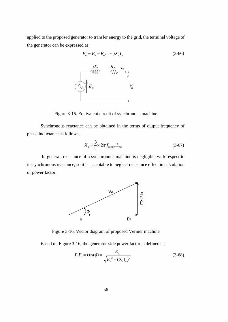
56
applied to the proposed generator to transfer energy to the grid, the terminal voltage of
the generator can be expressed as
a a a a s aV E R I jX I (3-66)
Figure 3-15. Equivalent circuit of synchronous machine
Synchronous reactance can be obtained in the terms of output frequency of
phase inductance as follows,
3
22
s vernier phX f L (3-67)
In general, resistance of a synchronous machine is negligible with respect to
its synchronous reactance, so it is acceptable to neglect resistance effect in calculation
of power factor.
Ia Ea
J*Xs
*IaVa
Ф
Figure 3-16. Vector diagram of proposed Vernier machine
Based on Figure 3-16, the generator-side power factor is defined as,
2 2
. . cos( )(X I )
a
a s a
EP F
E
(3-68)
57
After calculation of resistive and core losses, efficiency is calculated easily by
means of following equation,
out
out copper core
P
P P P
(3-69)

58
59
CHAPTER 4
OPTIMIZATION PROCEDURE OF DSSAVPM GENERATOR
4.1 Introduction
The optimum design of proposed permanent magnet Vernier machine may be
considered as a purely mathematical problem is non-linear programing. In general, a
constrained optimization problem may be formulated as follows:
Minimize C(x)
Subject to the constraints gi(x) < 0
For i=1, 2, …, m
Here, x is the vector of independent variable, C(x) is the objective function to
be satisfied and gi(x) is constraint function. In the case of electrical machines,
independent variables are normally dimensions of machine, objective function is the
volume, weight or the cost of machine and constraints are generally temperature rises
and operating flux density.
4.2 Optimization variables and constants
The optimum design of generator involves the search for a set of machine
dimensions which minimizes the volume, weight or cost of generator while satisfying
the specifications and constraints set up prior to design. In this chapter, choice of
constants, independent variables and constraints based on design criteria and
specifications will be given.
60
4.2.1 Constants
There are number of variables confronted in the design of proposed generator.
However some of them may safely be taken as constants, since they have a little
influence on the performance of machine or they are related to the physical properties
of material used in manufacturing. All of these constants and the reasons for their
choice will be discussed in the following sections.
4.2.1.1 Specifications taken as constants
Basic specifications of design problem such as output power, nominal speed
and terminal phase voltage are not permitted to vary throughout the optimization
procedure and they are taken as constants. These constant and their values can be listed
as follows,
Output power of machine Pout 50 kW
terminal phase voltage Vt 220 V
Shaft speed ns 60 rpm
4.2.1.2 Geometrical parameters taken as constants
These are the quantities which do not change much from machine to machine
with similar rating and have little influence on the performance and cost of the
machine. They are listed as follows,
Slot fill factor kcu 0.4
Bridge length br 1 mm
Tooth tip length htip 6 mm
61
4.2.1.3 Constants related to the physical properties of materials
These are the constants to take the physical properties of material into account
at the design stage. These constants are dependent on the materials used, so the type
of materials be used must be specified at the beginning of design procedure. These
constants may be listed as follows:
Stacking factor of laminations kstk 0.95
Copper mass density dcu 8933 kg/m3
Copper resistivity ρcu 1.7×10⁻⁸ Ω/m
Iron mass density diron 7872 kg/m3
PM mass density dmagnet 7550 kg/m3
Remanent flux density of magnet Br 1.2 T
Recoil permeability of magnet µrec 1.044
Saturation flux density of core Bsat 1.4 T
4.2.2 Independent variables
These are major dimensions and parameters of machine. They are chosen as
independent variables, since they have a major role in determining the performance of
the generator and the objective function. The independent variables are included in the
optimization process to find their optimum values for a specific objective function. On
this basis, the following dimensions of the proposed generator are the independent
variables in this work.
Bore diameter of outer stator Dg1
Magnet width Wm
62
Magnet arc ratio MAR
Slot opening ratio so
Number of stator pole pairs Ps
It is important to note that the selection of independent variables is not unique.
The reason why dimensions and parameters given above are selected to constitute the
set of independent variables is because most of the constraint functions are directly
related to these variables. Furthermore, by specification of independent variables,
other geometrical dimensions and parameters can be easily obtained from the
equations given in the previous chapter. In addition to the independent variables, there
are some variables chosen as parameters throughout the optimization problem. These
parameters are assigned constant values in a single optimization, but their values may
be varied from optimization to another. These parameters are listed below.
Air gap length g 1.5 mm
Gearing ratio GR 5, 11, 17
Outer stator electric loading qouter 12000 A/m
Inner stator electric loading qinner 10000 A/m
Outer stator current density Jouter 3 A/mm2
Inner stator current density Jinner 3 A/mm2
The length of the air gap is determined based on the generator bore diameter
and bearings type. In general, it is preferred to choose small value for the air gap to
maximize magnetic flux and minimize permanent magnet material usage. Since the air
gap length is chosen based on mechanical consideration, it is wise to include it in the
optimization as independent variables. So it is taken as parameter in the optimization
63
problem. In this study, it is assumed that length of both outer and inner air gaps are
constant and equal to 1.5 mm.
In order to see and compare the optimum design for each value of GR, it is also
excluded from optimization process. In other words, a separate optimization is
performed for each GR value. Then the most optimum solution is chosen among them.
Current densities and electrical loadings of outer and inner stators are other
four variables that are taken as parameter in this this study. These variables are
determined based on generator temperature rise. In order to find temperature rise of an
electrical machine, first of all it is necessary to calculate its losses based on performed
design and then evaluate its temperature rise using thermal analysis. But, at the
beginning of design, dimensions and losses of the machine are not available to perform
thermal analysis, so the values of these parameters are chosen from literature. Based
on the fact that cooling system is not devised for designed generator and it is naturally
cooled, windings current density is initially chosen 3 A/mm2, for both outer and inner
stators, and based on [24], electrical loadings of outer and inner stators are also
specified 12000 A/m and 10000 A/m, respectively.
4.3 Constraint functions
The constraint functions are the generator properties which determine the
general performance of the machine. The permissible limits for these properties are
specified at the beginning of design process. The differences between these constraints
and the specifications which are taken as constants are that constraint are permitted to
vary over a range. Therefore, during the optimization process, it is necessary to check
whether these are kept within the allowable boundaries. If a particular set of
independent variables cause violation of these constraints then the optimization path
that leads to these values is penalized and the search for optimum generator is forced
to progress in other directions.
Some of the constraints arise because of the material properties, while the
others come into picture because of the limitations on the electrical properties of
64
generator. If magnetic material in a generator is highly saturated, then an excessive
power loss may occur in some parts of magnetic material. This may cause temperature
rise of machine to exceed the limits set by the installation class, besides undesirable
hot spots may occur in the machine and the magnets would not be used efficiently.
Hence, the operating flux density in any part of machine needs to be kept under the
saturation flux density of the core material.
Beside constraints due to material properties, there are some other constraints
restricting independent variables. For instance, independent variables should be
greater than zero, since they are geometrical parameters and cannot take negative
values. Based on the definition of magnet arc (MAR) and slot opening (so), they are
fractions smaller than 1, so their values are allowed to vary between 0 and 1.
In addition to these constraints, there are other constraints which arise due to
mechanical constraints. Due to electromagnetic force imposed on winding, a machine
with thin teeth may not tolerate this force and teeth may be broken, so teeth width
should be restricted by a lower limit to protect them from breaking. In this study, the
lower boundary of tooth width is chosen 10 mm.
Beside tooth width limitation, there is a constraint in lower limit of the axial
length (Lstk). Due to mechanical issues, it is not practical to manufacture a machine
with very short axial length. The lower limit of axial length is restricted to 100 mm in
this study.
Finally the number of pole pairs must be an integer value. The non-integer pole
pairs is meaning-less. Therefore, optimization algorithm should assign integer values
to the number of pole pairs.
4.4 Objective Function
In the optimum design of the synchronous generator, the weight or volume,
cost and weight of magnetic materials can be taken as the objective function. The
objective function can be given as follows in general,
(x) Ciron iron iron cu cu cu mag mag magF d V C d V C d V (4-1)
65
Where, C, d and V are cost per unit of mass, mass density and volume. Viron,
Vcu and Vmag are calculated in section 3.7 of chapter 3. In the case of mass
minimization Ciron, Ccu and Cmag are taken as unity. In the case of volume minimization,
Ciron, Ccu, Cmag, diron, dcu and dmag are taken as unity. Costs per unit of mass and mass
densities are specified at the very beginning of the design. Therefore, if the volume of
iron and copper parts is given in the terms of presented independent variables and
constants, the generator mass and material cost can be found easily by multiplying the
volume by suitable factors. In this study, only mass optimization is performed.
4.5 Handling of the optimization problem
The purpose of any optimization problem is to discover the minimum value for
the objective function for specific sets of independent variables, constraint functions
and constants. The optimization process is composed of a lot of iterations. In the
beginning of each iteration, the optimization algorithm determines the values of
independent variables. Then objective function is calculated using governing
equations. Based on obtained objective function, optimization algorithm determines
the independent variables of next iteration. This process is kept on until the minimum
objective function is achieved and stopping criteria are satisfied.
The optimization process of the proposed DSSAVPM generator obeys the
above-mentioned general rules. First of all the optimization algorithm specifies the
independent variables at the beginning of each iteration. Second, the average flux
densities in the inner and outer air gaps are calculated using Finite Element (FE)
software. Third, the calculated air gap flux densities are exported to a MATLAB
function (it is possible to create a live-link between the FEM software and MATLAB).
Then the objective function is calculated using governing equations and the
optimization algorithm determines the independent variables of next iteration. Finally,
the calculated independent variables are transferred back to the FEM software through
the live-link to calculate the new air gap flux densities. Generally, the optimization
process can be summarized into the following steps,
66
Estimation of Bavg using FEM for each set of independent variables
Transferring calculated Bavg from FEM software to MATLAB.
Calculation of objective function in MATLAB determination of independent
variables for next iteration.
Transferring data back to the FEM software for next iteration calculations.
The above procedure is repeated until optimum solution is achieved. The
optimization is ceased when the stopping criteria are satisfied.
4.6 Optimization Flow chart
In this section, the flow chart of optimization procedure will be given. As it
was mentioned, proposed optimization algorithm is a Combination of FEM and
analytic calculation.
Flowchart of Figure 4-1 shows optimization procedure of the DSSAVPM
generator for a constant value of GR. In this algorithm, independent variables
including, Dg1, Wm, MAR, so and Ps are optimized to find the minimum objective
function. It should be noted that separate optimization is performed for each value of
the GR. By doing this, for each value of the GR, an optimized generator is obtained.
Then, the most optimum generator is chosen between the optimized generators
corresponding to the GR values based on the selection criteria. The optimization flow
chart consists of four main subprocesses including, specification of design criteria,
primary FEM model, analytic calculation and optimization. These parts will be
described in the following sections in more detail.
4.6.1 Specifications of constants and design criteria subprocess
In this subprocess, constants and constant-taken parameters are entered as
design criteria to optimization procedure. Design constants, parameters and initial
values of independent variables are specified in this subprocess. Detailed description
of each box is given as follows.
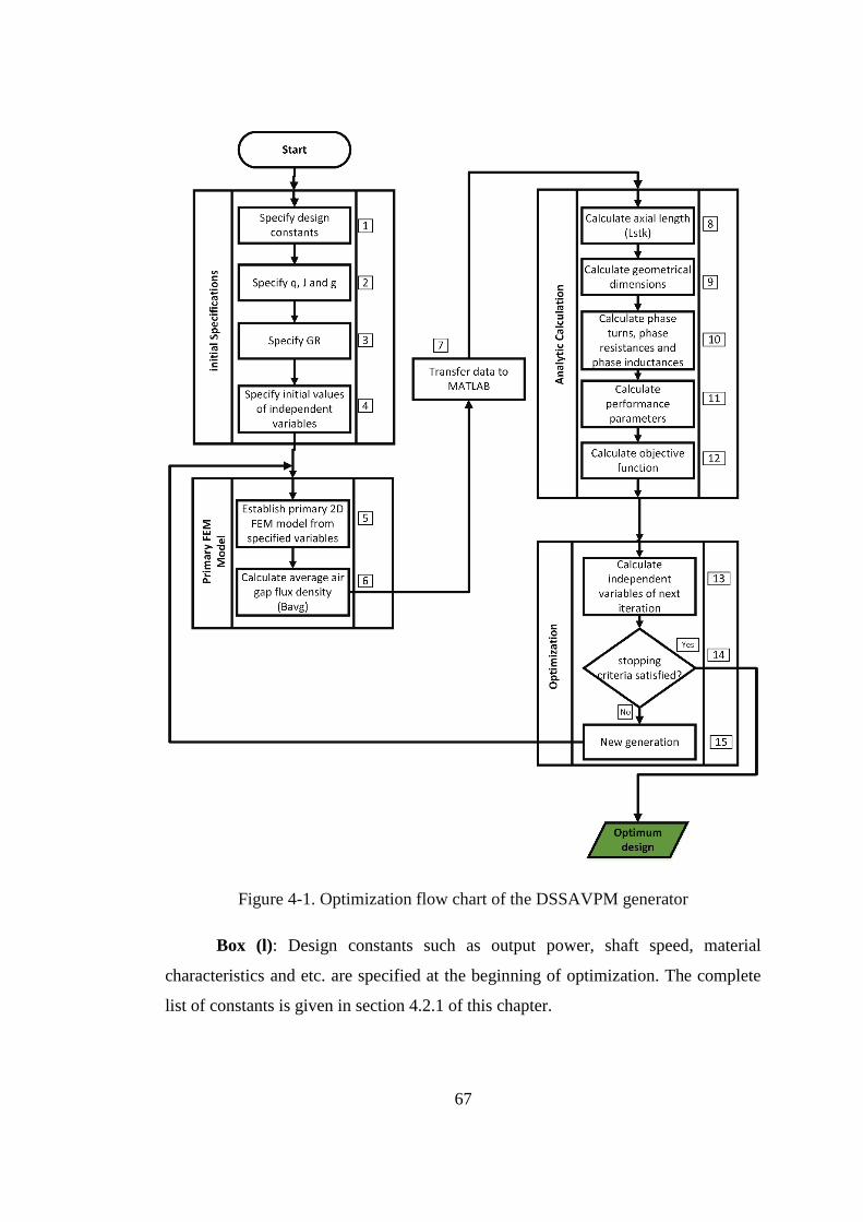
67
Figure 4-1. Optimization flow chart of the DSSAVPM generator
Box (l): Design constants such as output power, shaft speed, material
characteristics and etc. are specified at the beginning of optimization. The complete
list of constants is given in section 4.2.1 of this chapter.
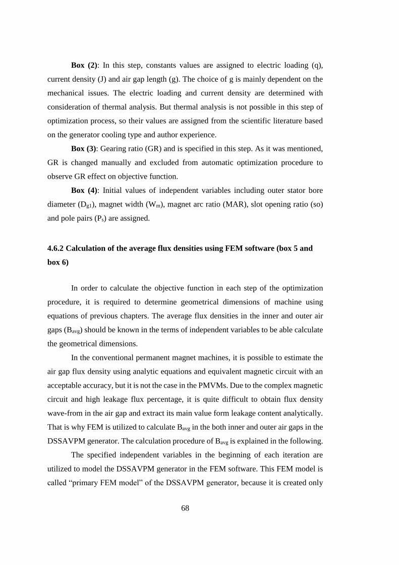
68
Box (2): In this step, constants values are assigned to electric loading (q),
current density (J) and air gap length (g). The choice of g is mainly dependent on the
mechanical issues. The electric loading and current density are determined with
consideration of thermal analysis. But thermal analysis is not possible in this step of
optimization process, so their values are assigned from the scientific literature based
on the generator cooling type and author experience.
Box (3): Gearing ratio (GR) and is specified in this step. As it was mentioned,
GR is changed manually and excluded from automatic optimization procedure to
observe GR effect on objective function.
Box (4): Initial values of independent variables including outer stator bore
diameter (Dg1), magnet width (Wm), magnet arc ratio (MAR), slot opening ratio (so)
and pole pairs (Ps) are assigned.
4.6.2 Calculation of the average flux densities using FEM software (box 5 and
box 6)
In order to calculate the objective function in each step of the optimization
procedure, it is required to determine geometrical dimensions of machine using
equations of previous chapters. The average flux densities in the inner and outer air
gaps (Bavg) should be known in the terms of independent variables to be able calculate
the geometrical dimensions.
In the conventional permanent magnet machines, it is possible to estimate the
air gap flux density using analytic equations and equivalent magnetic circuit with an
acceptable accuracy, but it is not the case in the PMVMs. Due to the complex magnetic
circuit and high leakage flux percentage, it is quite difficult to obtain flux density
wave-from in the air gap and extract its main value form leakage content analytically.
That is why FEM is utilized to calculate Bavg in the both inner and outer air gaps in the
DSSAVPM generator. The calculation procedure of Bavg is explained in the following.
The specified independent variables in the beginning of each iteration are
utilized to model the DSSAVPM generator in the FEM software. This FEM model is
called “primary FEM model” of the DSSAVPM generator, because it is created only
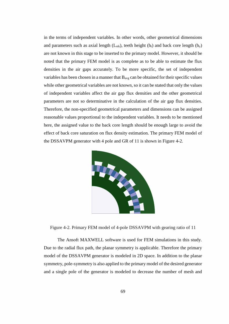
69
in the terms of independent variables. In other words, other geometrical dimensions
and parameters such as axial length (Lstk), teeth height (ht) and back core length (hy)
are not known in this stage to be inserted to the primary model. However, it should be
noted that the primary FEM model is as complete as to be able to estimate the flux
densities in the air gaps accurately. To be more specific, the set of independent
variables has been chosen in a manner that Bavg can be obtained for their specific values
while other geometrical variables are not known, so it can be stated that only the values
of independent variables affect the air gap flux densities and the other geometrical
parameters are not so determinative in the calculation of the air gap flux densities.
Therefore, the non-specified geometrical parameters and dimensions can be assigned
reasonable values proportional to the independent variables. It needs to be mentioned
here, the assigned value to the back core length should be enough large to avoid the
effect of back core saturation on flux density estimation. The primary FEM model of
the DSSAVPM generator with 4 pole and GR of 11 is shown in Figure 4-2.
Figure 4-2. Primary FEM model of 4-pole DSSAVPM with gearing ratio of 11
The Ansoft MAXWELL software is used for FEM simulations in this study.
Due to the radial flux path, the planar symmetry is applicable. Therefore the primary
model of the DSSAVPM generator is modeled in 2D space. In addition to the planar
symmetry, pole-symmetry is also applied to the primary model of the desired generator
and a single pole of the generator is modeled to decrease the number of mesh and
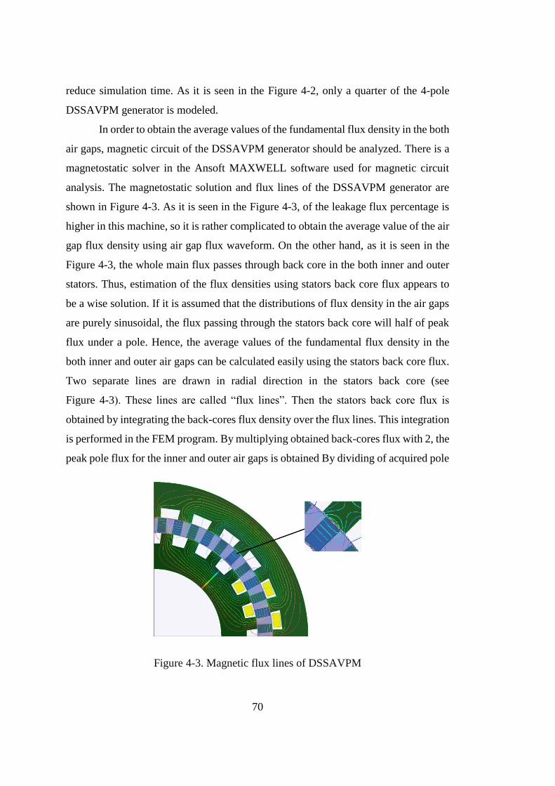
70
reduce simulation time. As it is seen in the Figure 4-2, only a quarter of the 4-pole
DSSAVPM generator is modeled.
In order to obtain the average values of the fundamental flux density in the both
air gaps, magnetic circuit of the DSSAVPM generator should be analyzed. There is a
magnetostatic solver in the Ansoft MAXWELL software used for magnetic circuit
analysis. The magnetostatic solution and flux lines of the DSSAVPM generator are
shown in Figure 4-3. As it is seen in the Figure 4-3, of the leakage flux percentage is
higher in this machine, so it is rather complicated to obtain the average value of the air
gap flux density using air gap flux waveform. On the other hand, as it is seen in the
Figure 4-3, the whole main flux passes through back core in the both inner and outer
stators. Thus, estimation of the flux densities using stators back core flux appears to
be a wise solution. If it is assumed that the distributions of flux density in the air gaps
are purely sinusoidal, the flux passing through the stators back core will half of peak
flux under a pole. Hence, the average values of the fundamental flux density in the
both inner and outer air gaps can be calculated easily using the stators back core flux.
Two separate lines are drawn in radial direction in the stators back core (see
Figure 4-3). These lines are called “flux lines”. Then the stators back core flux is
obtained by integrating the back-cores flux density over the flux lines. This integration
is performed in the FEM program. By multiplying obtained back-cores flux with 2, the
peak pole flux for the inner and outer air gaps is obtained By dividing of acquired pole
Figure 4-3. Magnetic flux lines of DSSAVPM
71
flux over pole areas, the average values of fundamental flux density in the inner and
outer air gaps are obtained. This calculation is performed for both inner and outer
stators.
In the next step, the calculated average flux densities (Bavg) are transferred to
MATLAB software to calculate objective function. There is an option in Ansoft
MAXWELL 16.0 which makes it possible to create a live-link between Ansoft
MAXWELL and MATLAB (box 7).
4.6.3 Analytic calculations using MATLAB
Once the air gap flux densities are estimated using FEM software in each
iteration, the geometrical dimensions, parameters and objective function of the
DSSAVPM generator can be calculated analytically using the given equations in
previous chapter. This is done by writing a MATLAB script. The calculation order in
each iteration for a specific set of independent variables and estimated average flux
densities is as follows.
Calculate axial length (Lstk) using Equation 3-14 (box 8)
Calculate outer and inner stators tooth width using Equations 3-19 and 3-32
(box 9).
Calculate outer and inner stators tooth height using Equations 3-23 and 3-34
(box 9).
Calculate outer and inner stators back core length using Equations 3-24 and 3-
30 (box 9).
Calculate outer and inner diameters using Equations 3-26 and 3-35 (box 9).
Calculate phase turns, phase resistances and phase inductance using Equations
3-38, 3-39 and 3-44 (box 10).
Calculate performance parameters (box 11).
Calculate generator mass (box 12).

72
4.6.4 Optimization method and tool (box 13 and box 14)
The explained procedure in previous sections shows how to obtain the
objective function in the terms of independent variables. In other words, the generator
can be designed and its mass can be calculated for each specific set of independent
variables. Thus, an optimization method can be utilized to find the optimum generator.
Based on previous explanation, the proposed optimization problem is a constrained
one. A basic technique in the solution of a constrained optimization problem is turning
it into an unconstrained problem. The penalty function method is utilized to convert a
constrained problem to unconstrained one. In this method, the unconstrained problems
are formed by adding a term, called a penalty function, to the objective function that
consists of a penalty parameter multiplied by a measure of violation of the constraints.
The measure of violation is nonzero when the constraints are violated and is zero in
the region where constraints are not violated.
In general, it is aimed to minimize a function F(x) of n variables subject to
inequality constraints of the form,
gi(x) ≤ 0
We will call Φ(k, t) for k ≥ 0, t ∈ R, a penalty function if
1. Φ is continuous.
2. Φ(k, t) ≥ 0 for all k and t
3. Φ(k, t)=0 for t ≤ 0 and Φ is strictly increasing for both k > 0 and t > 0
A common example of penalty function is,
0 for t<0
( , )t for t 0
k tk
To minimize f(x) subject to constraints, the following modified objective
function is defined,
1
( ) ( ) ( , ( ))n
new i i
i
F x F x k g x
Where ki is called penalty coefficient. It is a positive constants that control how
strongly constrains will be enforced. The penalty functions Φ modify the original
objective function so that if any inequality constraint is violated, a large penalty is
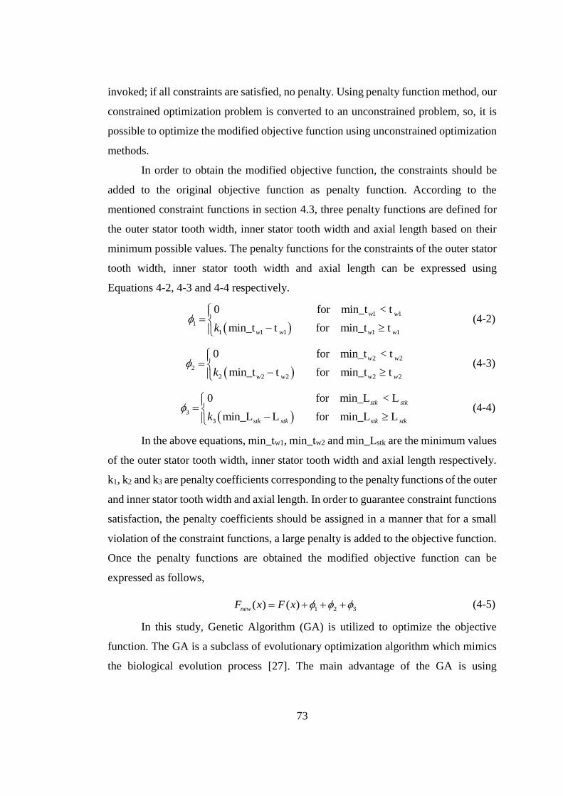
73
invoked; if all constraints are satisfied, no penalty. Using penalty function method, our
constrained optimization problem is converted to an unconstrained problem, so, it is
possible to optimize the modified objective function using unconstrained optimization
methods.
In order to obtain the modified objective function, the constraints should be
added to the original objective function as penalty function. According to the
mentioned constraint functions in section 4.3, three penalty functions are defined for
the outer stator tooth width, inner stator tooth width and axial length based on their
minimum possible values. The penalty functions for the constraints of the outer stator
tooth width, inner stator tooth width and axial length can be expressed using
Equations 4-2, 4-3 and 4-4 respectively.
1 1
1
1 1 1 1 1
0 for min_t < t
min_t t for min_t t
w w
w w w wk
(4-2)
2 2
2
2 2 2 2 2
0 for min_t < t
min_t t for min_t t
w w
w w w wk
(4-3)
3
3
0 for min_L < L
min_L L for min_L L
stk stk
stk stk stk stkk
(4-4)
In the above equations, min_tw1, min_tw2 and min_Lstk are the minimum values
of the outer stator tooth width, inner stator tooth width and axial length respectively.
k1, k2 and k3 are penalty coefficients corresponding to the penalty functions of the outer
and inner stator tooth width and axial length. In order to guarantee constraint functions
satisfaction, the penalty coefficients should be assigned in a manner that for a small
violation of the constraint functions, a large penalty is added to the objective function.
Once the penalty functions are obtained the modified objective function can be
expressed as follows,
1 2 3( ) ( )newF x F x (4-5)
In this study, Genetic Algorithm (GA) is utilized to optimize the objective
function. The GA is a subclass of evolutionary optimization algorithm which mimics
the biological evolution process [27]. The main advantage of the GA is using
74
derivative-free approach, which makes it a powerful tool for non-linear optimization
problems.
The GA is an iterative optimization method which generates a set of design
candidates based on individuals’ fitness values. The set of individuals in each
generation is called population. The GA utilizes the best individuals of each generation
to generate the individuals of next generation. Different crossover, mutation and
recombination methods are used to generate the individuals of next generation. Elites
count is the number of individuals that directly pass from one generation to another.
Higher number of crossover and mutation is suggested when it is intended to search in
a wider area and minimize the chance of trapping in a local minimum.
The MATLAB software has a powerful GA optimization toolbox. In this study
the MATLAB GA toolbox is utilized to perform the optimization of the DSSAVPM
generator. In this toolbox, the number of generations, populations, Elite count and
values of mutation and crossover factors are assigned by user. There is an option in
MATLAB GA toolbox which makes it possible to assign integer values to the poles
number. Furthermore, the convergence criteria are determined by stopping criteria of
GA toolbox. When one of the stopping criteria is satisfied, the optimum solution is
achieved and optimization is ceased. Various stopping criteria are available in
MATLAB GA toolbox. In this study the following stopping criteria are used to
determine the convergence criteria of the optimization problem.
Generations : the algorithm stops when the number of generations reaches the
specified value.
Function Tolerance : the algorithm runs until the average relative change in
the fitness function value over Stall generations is less than Function tolerance.
For more information about the MATLAB GA toolbox theory and options refer
to the MATLAB Help documentations.
75
4.7 Conclusion
The aim of this chapter is to develop an optimization procedure for the
DSSAVPM generator. For this purpose, first of all optimization constants, variables,
constraint functions and objective functions are introduced. Then the developed
optimization flowchart is given and each step of the optimization procedure is
explained in detail. Finally, MATLAB GA toolbox is chosen as optimization
algorithm. The optimization results will be presented in the chapter 6.

76
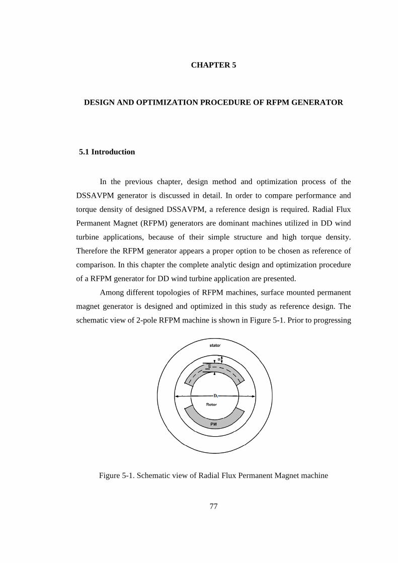
77
CHAPTER 5
DESIGN AND OPTIMIZATION PROCEDURE OF RFPM GENERATOR
5.1 Introduction
In the previous chapter, design method and optimization process of the
DSSAVPM generator is discussed in detail. In order to compare performance and
torque density of designed DSSAVPM, a reference design is required. Radial Flux
Permanent Magnet (RFPM) generators are dominant machines utilized in DD wind
turbine applications, because of their simple structure and high torque density.
Therefore the RFPM generator appears a proper option to be chosen as reference of
comparison. In this chapter the complete analytic design and optimization procedure
of a RFPM generator for DD wind turbine application are presented.
Among different topologies of RFPM machines, surface mounted permanent
magnet generator is designed and optimized in this study as reference design. The
schematic view of 2-pole RFPM machine is shown in Figure 5-1. Prior to progressing
Figure 5-1. Schematic view of Radial Flux Permanent Magnet machine
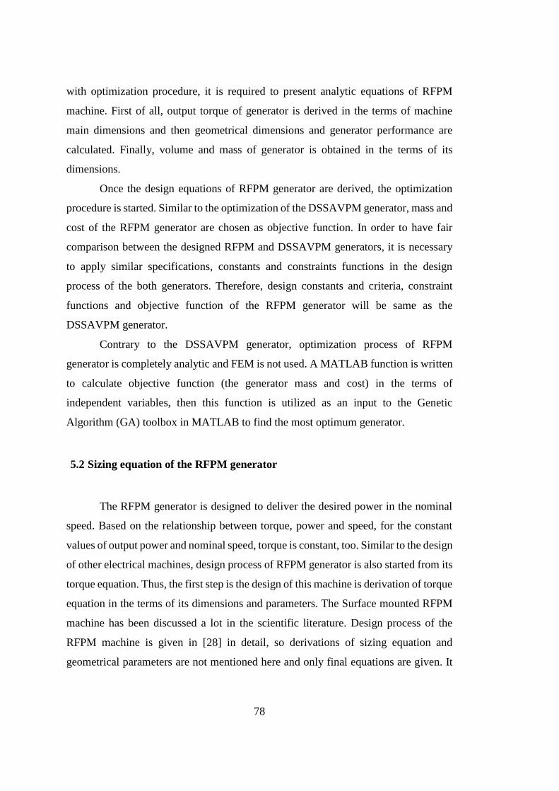
78
with optimization procedure, it is required to present analytic equations of RFPM
machine. First of all, output torque of generator is derived in the terms of machine
main dimensions and then geometrical dimensions and generator performance are
calculated. Finally, volume and mass of generator is obtained in the terms of its
dimensions.
Once the design equations of RFPM generator are derived, the optimization
procedure is started. Similar to the optimization of the DSSAVPM generator, mass and
cost of the RFPM generator are chosen as objective function. In order to have fair
comparison between the designed RFPM and DSSAVPM generators, it is necessary
to apply similar specifications, constants and constraints functions in the design
process of the both generators. Therefore, design constants and criteria, constraint
functions and objective function of the RFPM generator will be same as the
DSSAVPM generator.
Contrary to the DSSAVPM generator, optimization process of RFPM
generator is completely analytic and FEM is not used. A MATLAB function is written
to calculate objective function (the generator mass and cost) in the terms of
independent variables, then this function is utilized as an input to the Genetic
Algorithm (GA) toolbox in MATLAB to find the most optimum generator.
5.2 Sizing equation of the RFPM generator
The RFPM generator is designed to deliver the desired power in the nominal
speed. Based on the relationship between torque, power and speed, for the constant
values of output power and nominal speed, torque is constant, too. Similar to the design
of other electrical machines, design process of RFPM generator is also started from its
torque equation. Thus, the first step is the design of this machine is derivation of torque
equation in the terms of its dimensions and parameters. The Surface mounted RFPM
machine has been discussed a lot in the scientific literature. Design process of the
RFPM machine is given in [28] in detail, so derivations of sizing equation and
geometrical parameters are not mentioned here and only final equations are given. It
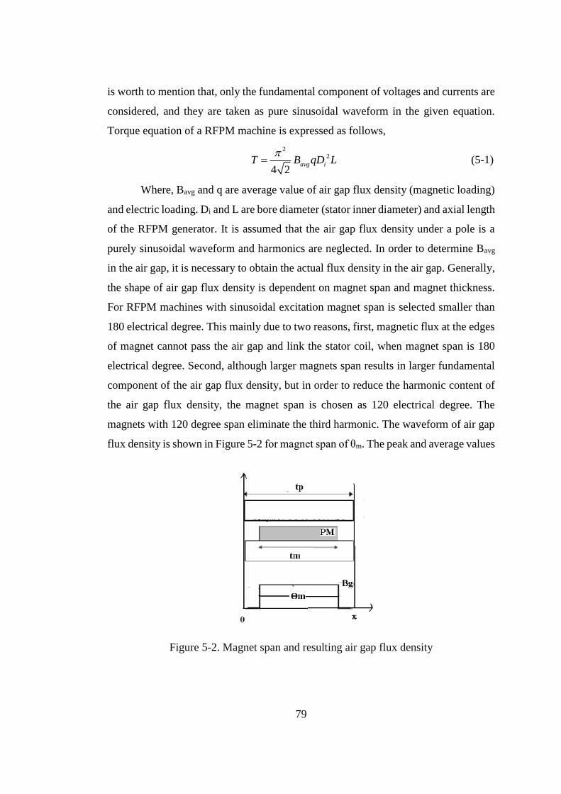
79
is worth to mention that, only the fundamental component of voltages and currents are
considered, and they are taken as pure sinusoidal waveform in the given equation.
Torque equation of a RFPM machine is expressed as follows,
2
2
4 2avg iT B qD L
(5-1)
Where, Bavg and q are average value of air gap flux density (magnetic loading)
and electric loading. Di and L are bore diameter (stator inner diameter) and axial length
of the RFPM generator. It is assumed that the air gap flux density under a pole is a
purely sinusoidal waveform and harmonics are neglected. In order to determine Bavg
in the air gap, it is necessary to obtain the actual flux density in the air gap. Generally,
the shape of air gap flux density is dependent on magnet span and magnet thickness.
For RFPM machines with sinusoidal excitation magnet span is selected smaller than
180 electrical degree. This mainly due to two reasons, first, magnetic flux at the edges
of magnet cannot pass the air gap and link the stator coil, when magnet span is 180
electrical degree. Second, although larger magnets span results in larger fundamental
component of the air gap flux density, but in order to reduce the harmonic content of
the air gap flux density, the magnet span is chosen as 120 electrical degree. The
magnets with 120 degree span eliminate the third harmonic. The waveform of air gap
flux density is shown in Figure 5-2 for magnet span of θm. The peak and average values
Figure 5-2. Magnet span and resulting air gap flux density
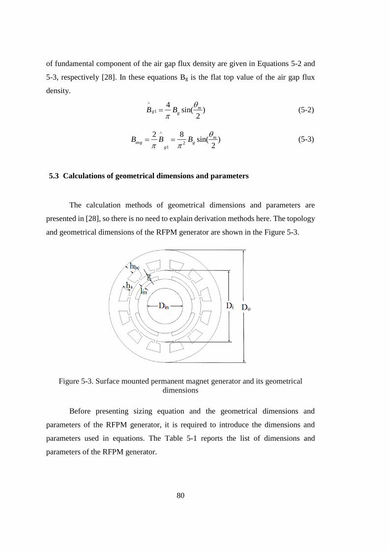
80
of fundamental component of the air gap flux density are given in Equations 5-2 and
5-3, respectively [28]. In these equations Bg is the flat top value of the air gap flux
density.
^
1
4sin( )
2
mg gB B
(5-2)
^
21
2 8sin( )
2
mavg g
g
B B B
(5-3)
5.3 Calculations of geometrical dimensions and parameters
The calculation methods of geometrical dimensions and parameters are
presented in [28], so there is no need to explain derivation methods here. The topology
and geometrical dimensions of the RFPM generator are shown in the Figure 5-3.
Figure 5-3. Surface mounted permanent magnet generator and its geometrical
dimensions
Before presenting sizing equation and the geometrical dimensions and
parameters of the RFPM generator, it is required to introduce the dimensions and
parameters used in equations. The Table 5-1 reports the list of dimensions and
parameters of the RFPM generator.
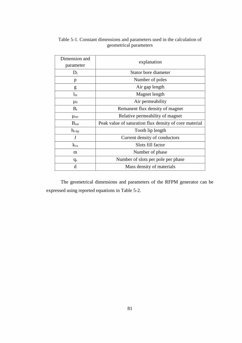
81
Table 5-1. Constant dimensions and parameters used in the calculation of
geometrical parameters
Dimension and
parameter explanation
Di Stator bore diameter
p Number of poles
g Air gap length
lm Magnet length
µ0 Air permeability
Br Remanent flux density of magnet
µrec Relative permeability of magnet
Bsat Peak value of saturation flux density of core material
ht-lip Tooth lip length
J Current density of conductors
kcu Slots fill factor
m Number of phase
qs Number of slots per pole per phase
d Mass density of materials
The geometrical dimensions and parameters of the RFPM generator can be
expressed using reported equations in Table 5-2.
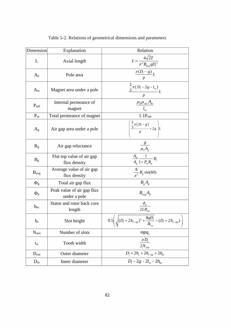
82
Table 5-2. Relations of geometrical dimensions and parameters
Dimension Explanation Relation
L Axial length 2 2
4 2
avg i
TL
B qD
Ap Pole area ( )iD g
Lp
Am Magnet area under a pole
22
3i mD g l
Lp
Pm0 Internal permeance of
magnet
0 rec m
m
A
l
Pm Total permeance of magnet 1.1Pm0
Ag Air gap area under a pole
2
3 2iD g
g Lp
Rg Air gap reluctance 0 p
g
A
Bg Flat top value of air gap
flux density
1
1
mr
g m g
AB
A P R
Bavg Average value of air gap
flux density 2
8sin(60)gB
Фg Total air gap flux g gB A
Фp Peak value of air gap flux
under a pole avg pB A
hbc Stator and rotor back core
length 2
g
satLB
hs Slot height 2 8
0.5 ( 2h ) ( 2h )ii t lip i t lip
cu
qDD D
Jk
Nslot Number of slots smpq
tw Tooth width 2
i
slot
D
N
Dout Outer diameter 2 2 2i s t lip bcD h h h
Din Inner diameter 2 2 2i m bcD g l h
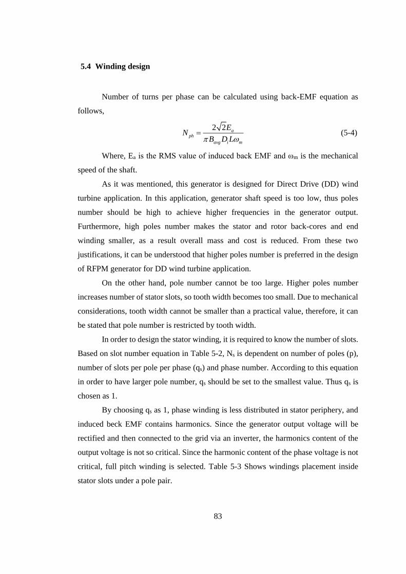
83
5.4 Winding design
Number of turns per phase can be calculated using back-EMF equation as
follows,
2 2 a
ph
avg i m
EN
B D L (5-4)
Where, Ea is the RMS value of induced back EMF and ωm is the mechanical
speed of the shaft.
As it was mentioned, this generator is designed for Direct Drive (DD) wind
turbine application. In this application, generator shaft speed is too low, thus poles
number should be high to achieve higher frequencies in the generator output.
Furthermore, high poles number makes the stator and rotor back-cores and end
winding smaller, as a result overall mass and cost is reduced. From these two
justifications, it can be understood that higher poles number is preferred in the design
of RFPM generator for DD wind turbine application.
On the other hand, pole number cannot be too large. Higher poles number
increases number of stator slots, so tooth width becomes too small. Due to mechanical
considerations, tooth width cannot be smaller than a practical value, therefore, it can
be stated that pole number is restricted by tooth width.
In order to design the stator winding, it is required to know the number of slots.
Based on slot number equation in Table 5-2, Ns is dependent on number of poles (p),
number of slots per pole per phase (qs) and phase number. According to this equation
in order to have larger pole number, qs should be set to the smallest value. Thus qs is
chosen as 1.
By choosing qs as 1, phase winding is less distributed in stator periphery, and
induced beck EMF contains harmonics. Since the generator output voltage will be
rectified and then connected to the grid via an inverter, the harmonics content of the
output voltage is not so critical. Since the harmonic content of the phase voltage is not
critical, full pitch winding is selected. Table 5-3 Shows windings placement inside
stator slots under a pole pair.
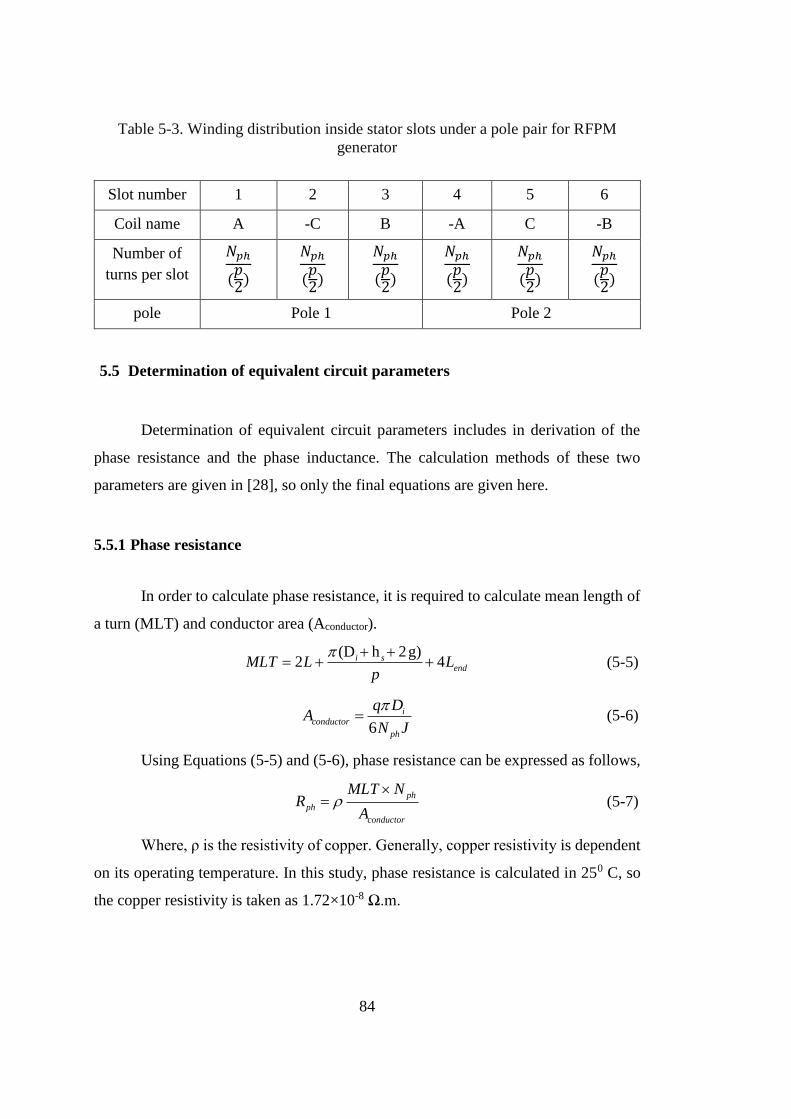
84
Table 5-3. Winding distribution inside stator slots under a pole pair for RFPM
generator
Slot number 1 2 3 4 5 6
Coil name A -C B -A C -B
Number of
turns per slot
𝑁𝑝ℎ
(𝑝2)
𝑁𝑝ℎ
(𝑝2)
𝑁𝑝ℎ
(𝑝2)
𝑁𝑝ℎ
(𝑝2)
𝑁𝑝ℎ
(𝑝2)
𝑁𝑝ℎ
(𝑝2)
pole Pole 1 Pole 2
5.5 Determination of equivalent circuit parameters
Determination of equivalent circuit parameters includes in derivation of the
phase resistance and the phase inductance. The calculation methods of these two
parameters are given in [28], so only the final equations are given here.
5.5.1 Phase resistance
In order to calculate phase resistance, it is required to calculate mean length of
a turn (MLT) and conductor area (Aconductor).
(D h 2g)
2 4i sendMLT L L
p
(5-5)
6
iconductor
ph
q DA
N J
(5-6)
Using Equations (5-5) and (5-6), phase resistance can be expressed as follows,
ph
ph
conductor
MLT NR
A
(5-7)
Where, ρ is the resistivity of copper. Generally, copper resistivity is dependent
on its operating temperature. In this study, phase resistance is calculated in 250 C, so
the copper resistivity is taken as 1.72×10⁻⁸ Ω.m.
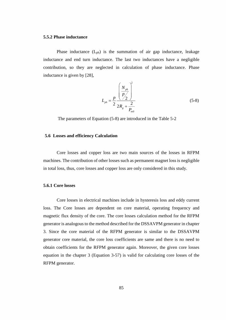
85
5.5.2 Phase inductance
Phase inductance (Lph) is the summation of air gap inductance, leakage
inductance and end turn inductance. The last two inductances have a negligible
contribution, so they are neglected in calculation of phase inductance. Phase
inductance is given by [28],
2
0
222
2
ph
ph
g
m
N
pp
L
RP
(5-8)
The parameters of Equation (5-8) are introduced in the Table 5-2
5.6 Losses and efficiency Calculation
Core losses and copper loss are two main sources of the losses in RFPM
machines. The contribution of other losses such as permanent magnet loss is negligible
in total loss, thus, core losses and copper loss are only considered in this study.
5.6.1 Core losses
Core losses in electrical machines include in hysteresis loss and eddy current
loss. The Core losses are dependent on core material, operating frequency and
magnetic flux density of the core. The core losses calculation method for the RFPM
generator is analogous to the method described for the DSSAVPM generator in chapter
3. Since the core material of the RFPM generator is similar to the DSSAVPM
generator core material, the core loss coefficients are same and there is no need to
obtain coefficients for the RFPM generator again. Moreover, the given core losses
equation in the chapter 3 (Equation 3-57) is valid for calculating core losses of the
RFPM generator.
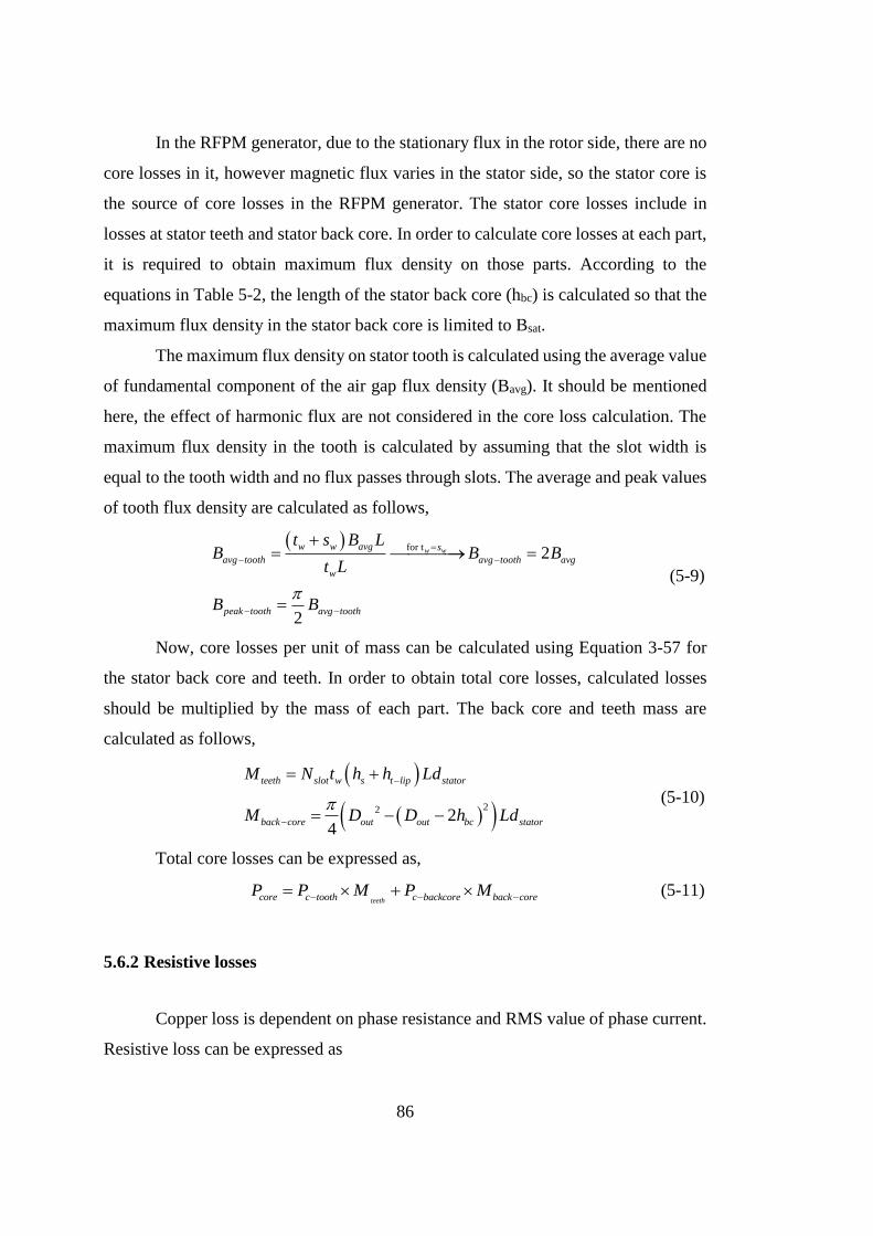
86
In the RFPM generator, due to the stationary flux in the rotor side, there are no
core losses in it, however magnetic flux varies in the stator side, so the stator core is
the source of core losses in the RFPM generator. The stator core losses include in
losses at stator teeth and stator back core. In order to calculate core losses at each part,
it is required to obtain maximum flux density on those parts. According to the
equations in Table 5-2, the length of the stator back core (hbc) is calculated so that the
maximum flux density in the stator back core is limited to Bsat.
The maximum flux density on stator tooth is calculated using the average value
of fundamental component of the air gap flux density (Bavg). It should be mentioned
here, the effect of harmonic flux are not considered in the core loss calculation. The
maximum flux density in the tooth is calculated by assuming that the slot width is
equal to the tooth width and no flux passes through slots. The average and peak values
of tooth flux density are calculated as follows,
for t2
2
w ww w avg s
avg tooth avg tooth avg
w
peak tooth avg tooth
t s B LB B B
t L
B B
(5-9)
Now, core losses per unit of mass can be calculated using Equation 3-57 for
the stator back core and teeth. In order to obtain total core losses, calculated losses
should be multiplied by the mass of each part. The back core and teeth mass are
calculated as follows,
22 24
teeth slot w s t lip stator
back core out out bc stator
M N t h h Ld
M D D h Ld
(5-10)
Total core losses can be expressed as,
teethcore c tooth c backcore back coreP P M P M (5-11)
5.6.2 Resistive losses
Copper loss is dependent on phase resistance and RMS value of phase current.
Resistive loss can be expressed as
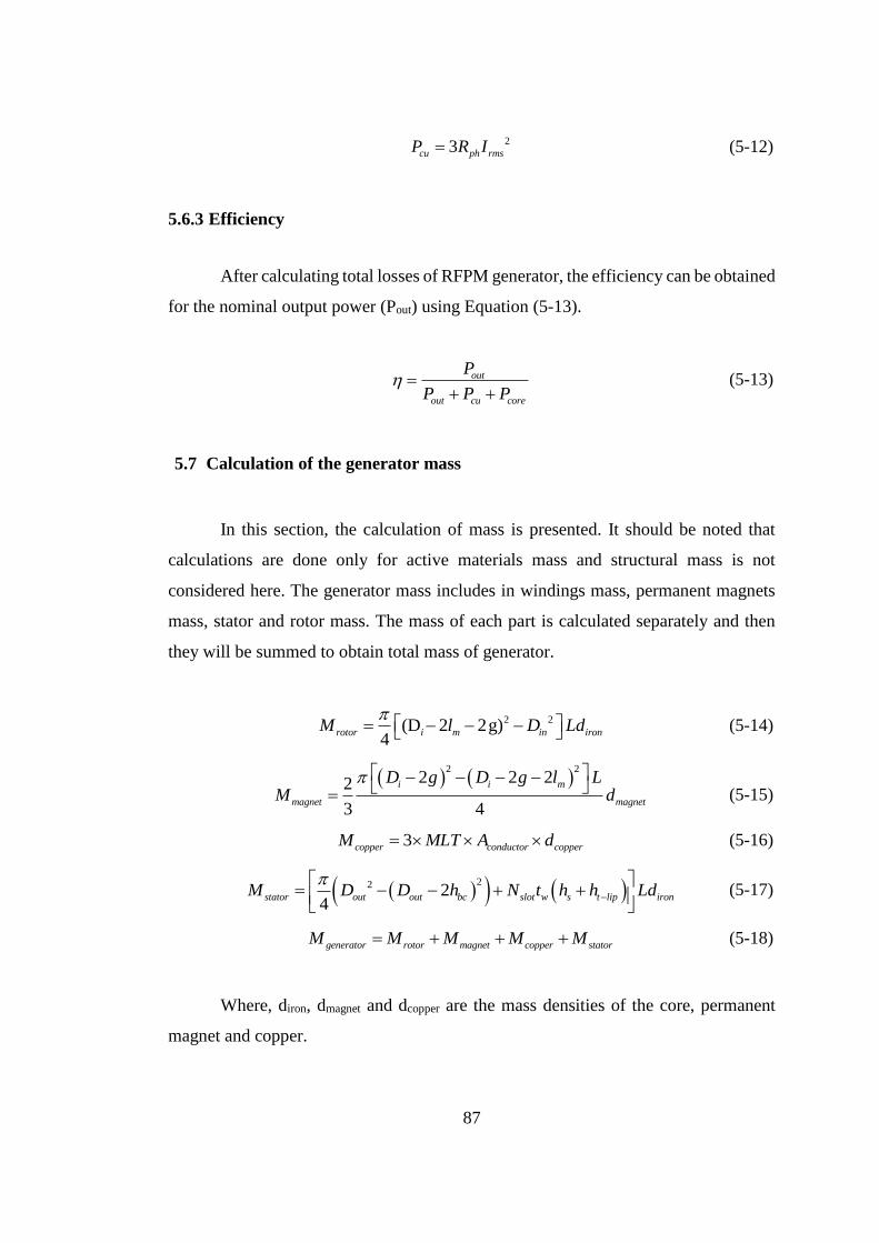
87
23cu ph rmsP R I (5-12)
5.6.3 Efficiency
After calculating total losses of RFPM generator, the efficiency can be obtained
for the nominal output power (Pout) using Equation (5-13).
out
out cu core
P
P P P
(5-13)
5.7 Calculation of the generator mass
In this section, the calculation of mass is presented. It should be noted that
calculations are done only for active materials mass and structural mass is not
considered here. The generator mass includes in windings mass, permanent magnets
mass, stator and rotor mass. The mass of each part is calculated separately and then
they will be summed to obtain total mass of generator.
2 2(D 2 2g)
4rotor i m in ironM l D Ld
(5-14)
2 22 2 22
3 4
i i m
magnet magnet
D g D g l LM d
(5-15)
3copper conductor copperM MLT A d (5-16)
22 2
4stator out out bc slot w s t lip ironM D D h N t h h Ld
(5-17)
generator rotor magnet copper statorM M M M M (5-18)
Where, diron, dmagnet and dcopper are the mass densities of the core, permanent
magnet and copper.
88
5.8 Optimization procedure of the RFPM generator
The main goal of author in this section is to develop an optimization process
for the RFPM generator. The design process of the RFPM generator is presented in the
previous section. Once the design constants are specified, it is possible to calculate the
geometrical parameters, performance, mass and cost of the RFPM generator in the
terms of specified independent variables. In the optimization process, it is aimed to
find the optimum value of independent variables to minimize the objective function.
Similar to the DSSAVPM generator, mass of the RFPM generator are chosen as
objective function. Therefore, the developed design process can be used as an input to
an optimization algorithm to achieve the most optimum design.
In this section, the optimization procedure of the RFPM generator is discussed.
First, the optimization problem is clarified and constants, independent variables,
constraint functions and objective function are determined and discussed. Then
optimization method and algorithm are explained.
5.8.1 Optimization constants
During the optimization process, some parameters are chosen to be constant,
fixed values are assigned to them throughout the process. Design specifications are
taken as constant in this study. In addition, some geometrical parameters which are
determined based on mechanical and electrical considerations are also selected to be
constant. Materials properties also do not change during optimization, so some
constants are also arose due to materials. The optimizations constants can be classified
as follows,
5.8.1.1 Design specification taken as constant
Output power of machine Pout 50 kW
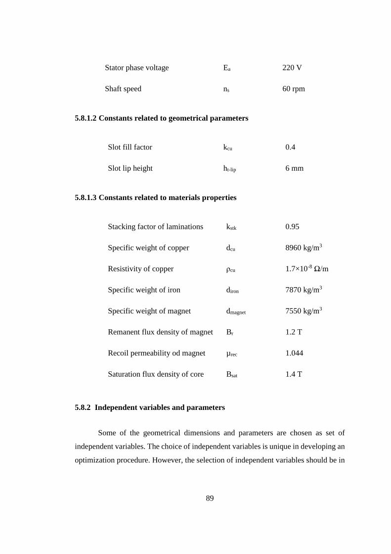
89
Stator phase voltage Ea 220 V
Shaft speed ns 60 rpm
5.8.1.2 Constants related to geometrical parameters
Slot fill factor kcu 0.4
Slot lip height ht-lip 6 mm
5.8.1.3 Constants related to materials properties
Stacking factor of laminations kstk 0.95
Specific weight of copper dcu 8960 kg/m3
Resistivity of copper ρcu 1.7×10⁻⁸ Ω/m
Specific weight of iron diron 7870 kg/m3
Specific weight of magnet dmagnet 7550 kg/m3
Remanent flux density of magnet Br 1.2 T
Recoil permeability od magnet µrec 1.044
Saturation flux density of core Bsat 1.4 T
5.8.2 Independent variables and parameters
Some of the geometrical dimensions and parameters are chosen as set of
independent variables. The choice of independent variables is unique in developing an
optimization procedure. However, the selection of independent variables should be in
90
a way that makes it possible to calculate the generator geometrical dimensions,
parameters and performance. In this work, following variables are chosen to be
independent variables of the optimization process.
Stator bore diameter Di
Magnet length lm
Number of stator poles P
In addition to the independent variables, there are some parameters called
independent parameters. These parameters are mainly determined based on non-
electrical issues. In other words, mechanical and thermal considerations have principal
contributions in determination of these parameters. Therefore, it is not reasonable to
include them in the electric optimization process. The independent parameters take
constant value throughout a single optimization. However, the value may be varied
from one optimization to another. The independent variables are listed below.
Air gap length g 1.5 mm
Stator electric loading q 22000 A/m
Conductors current density J 3 A/mm2
Although, air gap length (g) has major impacts on generator performance and
mass, but it does not seem too reasonable to take it as independent variable. From
electric point of view, smaller air gap lengths are preferred. But the air gap length is
restricted due to mechanical consideration and it is determined regarding ball bearing
type, bore diameter and axial length of the machine. Similar to the DSSAVPM
generator, the air gap length for the RFPM generator is selected as 1.5 mm.
In addition to air gap length (g), the electric loading (q) and the current density
(J) of the RFPM generator are as independent parameters. From electric point of view,
larger values of q and J make the generator lighter. On the other hand, q and J are
limited by the generator temperature rise. The maximum temperature of the generator
goes up when q and J are increased. Therefore, similar to the air gap length, the electric
91
loading and current density of the RFPM generator are excluded from optimization
process and assigned fixed values throughout an optimization. As it was mentioned
before, the RFPM generator is designed and optimized to create a reference of
comparison for the optimized DSSAVPM generator. In order to have a fair comparison
between the design and optimization should be done under similar conditions. Hence,
the electric loading and current density of the RFPM generator will be same as the
specified values for the DSSAVPM generator.
5.8.3 Constraint functions
During the design and optimization process, performance and parameters of
the generator are limited by different constraint functions. These constraint may arise
due to electrical, mechanical or thermal issues. The existed constraint functions in the
optimization of the RFPM generator are described below.
The maximum flux density of the core material in the optimized RFPM
generator should be restricted. If the core material is saturated, the core losses are
increased. Therefore, the core flux density should be kept under the saturation point of
the core material. The RFPM generator core is composed of back core and teeth.
According to the equations of Table 5-2, the rotor and stator back core are designed so
that the back core flux density does not exceed saturation flux density of the core
material. So, there is no need to put a constraint on the back core flux density.
On the other hand, the tooth flux density is not controlled to be kept under the
saturation flux density in the design process. Thus, a constraint should be considered
in the optimization process to keep the tooth flux density under Bsat.
There are some other constraints imposed to the design and optimization
procedure of the RFPM generator due to mechanical considerations. Same as the
DSSAVPM generator, the tooth width in the RFPM generator is not allowed to be
smaller than 10 mm. Moreover, the applied constraint to the axial length of the
DSSAVPM generator is also applied to the RFPM generator to keep its axial length
larger than 100 mm.
92
Another constraint arose due to the fact that pole number must take an even
integer value.
5.8.4 Objective function
Since the RFPM generator is designed as a comparison reference for the
DSSAVPM generator, it is optimized for the same objective function. Therefore,
similar to the DSSAVPM generator, mass of the RFPM generator are minimized in
the optimization process. The calculation method of the RFPM generator mass is given
in section 5.2.5.
5.8.5 Handling of the optimization problem
In order to calculate objective function for each specific set of independent
variables, A MATLAB function is written based on the presented analytic equations.
The inputs of this function are independent variables and the output is the generator
mass. The calculated objective function is fed into a proper optimization algorithm to
find the optimum generator for desired specifications while constraint functions are
satisfied. Optimization method and algorithm are explained in following sections in
detail.
5.8.5.1 Optimization method
The discussed constraints in the section 5.3.3 indicate that the optimization
problem of the RFPM generator is a constrained one. Similar to the DSSAVPM
generator, the optimization problem of the RFPM generator may be changed to an
unconstrained problem. To convert constrained optimization problem into an
unconstrained one, penalty function method is used. This method is explained in
optimization process of the DSSAVPM generator in detail. The same approach is
utilized here for the RFPM generator. Defined penalty functions for the constraints of
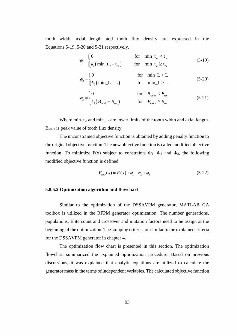
93
tooth width, axial length and tooth flux density are expressed in the
Equations 5-19, 5-20 and 5-21 respectively.
1
1
0 for min_t < t
min_t t for min_t t
w w
w w w wk
(5-19)
2
2
0 for min_L < L
min_L L for min_L Lk
(5-20)
3
3
0 for <
for
tooth sat
tooth sat tooth sat
B B
k B B B B
(5-21)
Where min_tw and min_L are lower limits of the tooth width and axial length.
Btooth is peak value of tooth flux density.
The unconstrained objective function is obtained by adding penalty function to
the original objective function. The new objective function is called modified objective
function. To minimize F(x) subject to constraints Ф1, Ф2 and Ф3, the following
modified objective function is defined,
1 2 3( ) ( )newF x F x (5-22)
5.8.5.2 Optimization algorithm and flowchart
Similar to the optimization of the DSSAVPM generator, MATLAB GA
toolbox is utilized in the RFPM generator optimization. The number generations,
populations, Elite count and crossover and mutation factors need to be assign at the
beginning of the optimization. The stopping criteria are similar to the explained criteria
for the DSSAVPM generator in chapter 4.
The optimization flow chart is presented in this section. The optimization
flowchart summarized the explained optimization procedure. Based on previous
discussions, it was explained that analytic equations are utilized to calculate the
generator mass in the terms of independent variables. The calculated objective function
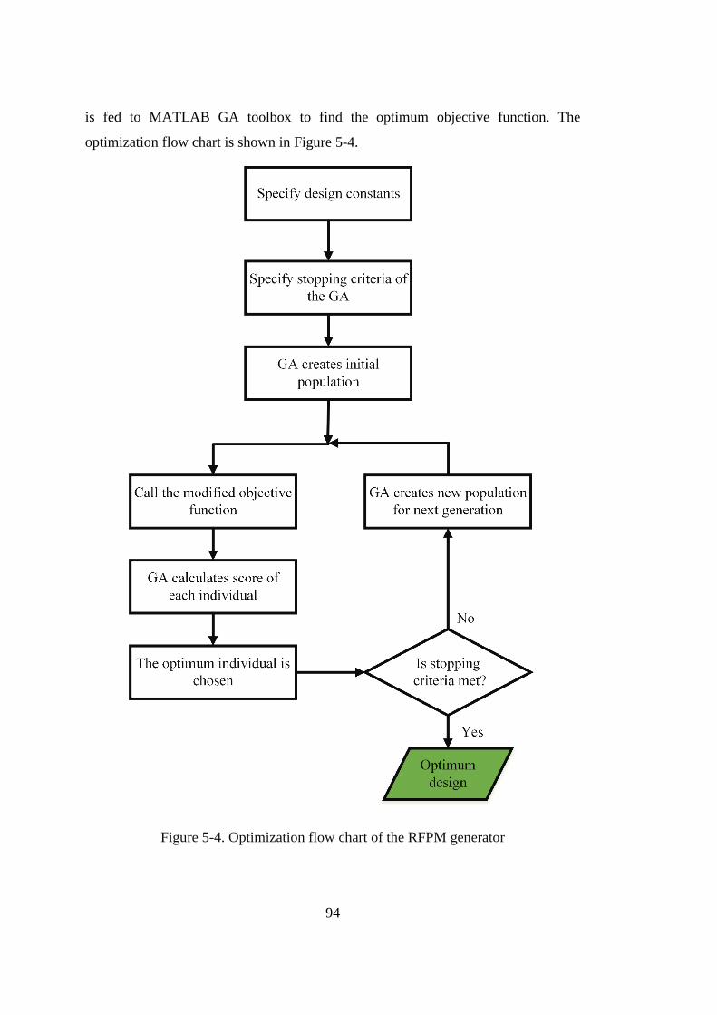
94
is fed to MATLAB GA toolbox to find the optimum objective function. The
optimization flow chart is shown in Figure 5-4.
Figure 5-4. Optimization flow chart of the RFPM generator
95
CHAPTER 6
ACTIVE MASS OPTIMIZATION RESULTS FOR THE DSSAVPM AND
RFPM GENERATORS
6.1 Introduction
In this chapter active-mass optimization results for the DSSAVPM and RFPM
generators are presented separately. First of all, parameters and specifications of the
optimization process and GA toolbox are assigned. Then the optimization is performed
under the specified conditions and corresponding optimization results are presented
for the DSSAVPM and RFPM generators. Then, the optimized DSSAVPM generator
is compared with the RFPM generator from different points of view and its advantages
and disadvantages with respect to the RFPM generator are discussed. Finally, the effect
of the structural geometry on design and optimization of the DSSAVPM and RFPM
generators is argued.
6.2 Active mass optimization of the DSSAVPM generator
In this section, active-mass optimization results for the DSSAVPM generator
are given. Before proceeding with the optimization, it is necessary to allocate the
constants and parameters of the optimization procedure. Some optimization constants
and parameters of the DSSAVPM generator are specified in the chapter 4. The
remaining non-specified parameters are Gearing Ratio (GR), penalty coefficients and
GA specifications. In the following section the mentioned parameters are specified and
then corresponding active-mass optimization results are presented.
96
6.2.1 Possible choices for GR
As it was discussed in chapter 4, GR is excluded from optimization procedure
to observe its effect on optimization results. Therefore, it is necessary to implement a
separate optimization for each GR values to perceive its influences on optimum fitness
function and performance parameters. In this section the possible GR choices are
discussed. GR cannot take any arbitrary value. The GR values must be chosen so that
the number of slots per pole per phase does not become a non-integer value. The
number of slots per pole per phase (qs) can be obtained using following equation.
2
ss
s
Zq
m P
(6-1)
Where, m is the number of phase which is 3 for proposed DSSAVPM
generator. Zs and Ps are number of stator slots and pole pairs respectively. According
to the following equation, slot number is a function of GR.
1r sP P GR
s r s s sZ P P Z P GR
(6-2)
By combining two previous equations, qs can be expressed in the terms of GR
as following,
1 1
2 2
s
s
s
P GR GRq
m P m
(6-3)
Sine qs can only take integer values, so GR values are obtained using following
expression,
1
6 1 (k=1, 2, 3, ...)2 3
GRk GR k
(6-4)
In this study, the DSSAVPM generator is evaluated only for three GRs of 5, 11
and 17. From this point onward the DSSAVPM generators with GRs of 5, 11 and 17
are referred with DSSAVPM_5, DSSAVPM_11 and DSSAVPM_17 respectively.
Larger GRs are not considered because optimization results will indicate that larger
GRs do not offer considerable improvement in optimum generator. Furthermore,
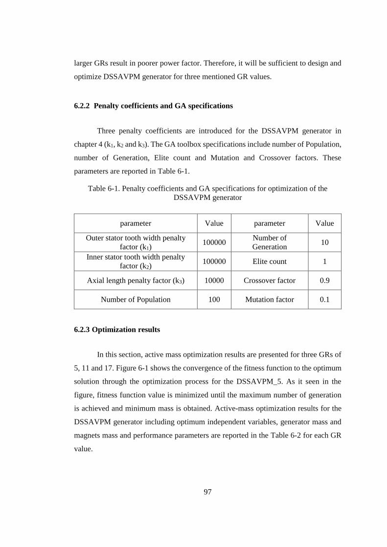
97
larger GRs result in poorer power factor. Therefore, it will be sufficient to design and
optimize DSSAVPM generator for three mentioned GR values.
6.2.2 Penalty coefficients and GA specifications
Three penalty coefficients are introduced for the DSSAVPM generator in
chapter 4 (k1, k2 and k3). The GA toolbox specifications include number of Population,
number of Generation, Elite count and Mutation and Crossover factors. These
parameters are reported in Table 6-1.
Table 6-1. Penalty coefficients and GA specifications for optimization of the
DSSAVPM generator
parameter Value parameter Value
Outer stator tooth width penalty
factor (k1) 100000
Number of
Generation 10
Inner stator tooth width penalty
factor (k2) 100000 Elite count 1
Axial length penalty factor (k3) 10000 Crossover factor 0.9
Number of Population 100 Mutation factor 0.1
6.2.3 Optimization results
In this section, active mass optimization results are presented for three GRs of
5, 11 and 17. Figure 6-1 shows the convergence of the fitness function to the optimum
solution through the optimization process for the DSSAVPM_5. As it seen in the
figure, fitness function value is minimized until the maximum number of generation
is achieved and minimum mass is obtained. Active-mass optimization results for the
DSSAVPM generator including optimum independent variables, generator mass and
magnets mass and performance parameters are reported in the Table 6-2 for each GR
value.
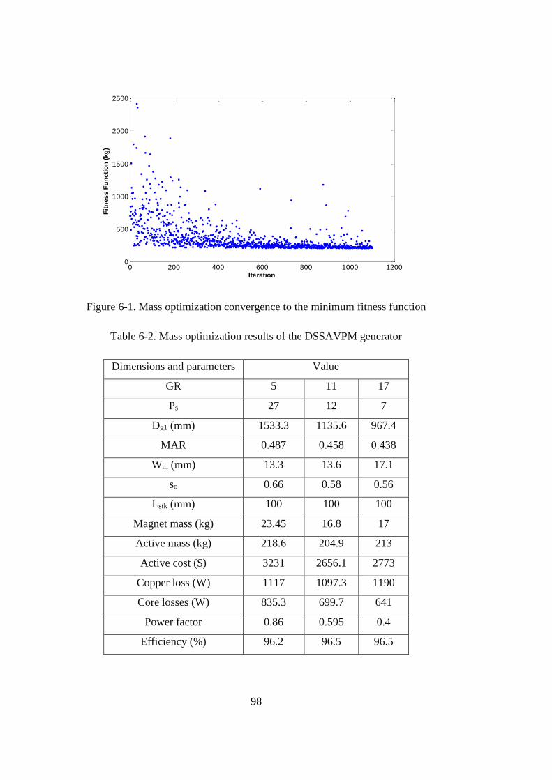
98
Figure 6-1. Mass optimization convergence to the minimum fitness function
Table 6-2. Mass optimization results of the DSSAVPM generator
Dimensions and parameters Value
GR 5 11 17
Ps 27 12 7
Dg1 (mm) 1533.3 1135.6 967.4
MAR 0.487 0.458 0.438
Wm (mm) 13.3 13.6 17.1
so 0.66 0.58 0.56
Lstk (mm) 100 100 100
Magnet mass (kg) 23.45 16.8 17
Active mass (kg) 218.6 204.9 213
Active cost ($) 3231 2656.1 2773
Copper loss (W) 1117 1097.3 1190
Core losses (W) 835.3 699.7 641
Power factor 0.86 0.595 0.4
Efficiency (%) 96.2 96.5 96.5
0 200 400 600 800 1000 12000
500
1000
1500
2000
2500
Iteration
Fit
ness F
un
cti
on
(kg
)
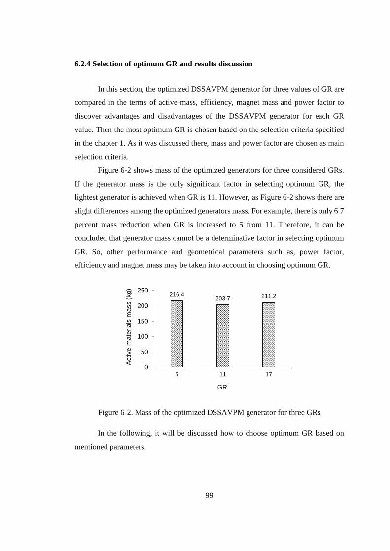
99
6.2.4 Selection of optimum GR and results discussion
In this section, the optimized DSSAVPM generator for three values of GR are
compared in the terms of active-mass, efficiency, magnet mass and power factor to
discover advantages and disadvantages of the DSSAVPM generator for each GR
value. Then the most optimum GR is chosen based on the selection criteria specified
in the chapter 1. As it was discussed there, mass and power factor are chosen as main
selection criteria.
Figure 6-2 shows mass of the optimized generators for three considered GRs.
If the generator mass is the only significant factor in selecting optimum GR, the
lightest generator is achieved when GR is 11. However, as Figure 6-2 shows there are
slight differences among the optimized generators mass. For example, there is only 6.7
percent mass reduction when GR is increased to 5 from 11. Therefore, it can be
concluded that generator mass cannot be a determinative factor in selecting optimum
GR. So, other performance and geometrical parameters such as, power factor,
efficiency and magnet mass may be taken into account in choosing optimum GR.
Figure 6-2. Mass of the optimized DSSAVPM generator for three GRs
In the following, it will be discussed how to choose optimum GR based on
mentioned parameters.
216.4203.7 211.2
0
50
100
150
200
250
5 11 17
Active m
ate
rials
mass (
kg)
GR
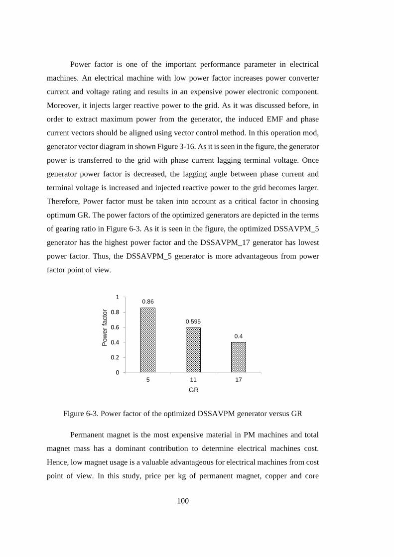
100
Power factor is one of the important performance parameter in electrical
machines. An electrical machine with low power factor increases power converter
current and voltage rating and results in an expensive power electronic component.
Moreover, it injects larger reactive power to the grid. As it was discussed before, in
order to extract maximum power from the generator, the induced EMF and phase
current vectors should be aligned using vector control method. In this operation mod,
generator vector diagram in shown Figure 3-16. As it is seen in the figure, the generator
power is transferred to the grid with phase current lagging terminal voltage. Once
generator power factor is decreased, the lagging angle between phase current and
terminal voltage is increased and injected reactive power to the grid becomes larger.
Therefore, Power factor must be taken into account as a critical factor in choosing
optimum GR. The power factors of the optimized generators are depicted in the terms
of gearing ratio in Figure 6-3. As it is seen in the figure, the optimized DSSAVPM_5
generator has the highest power factor and the DSSAVPM_17 generator has lowest
power factor. Thus, the DSSAVPM_5 generator is more advantageous from power
factor point of view.
Figure 6-3. Power factor of the optimized DSSAVPM generator versus GR
Permanent magnet is the most expensive material in PM machines and total
magnet mass has a dominant contribution to determine electrical machines cost.
Hence, low magnet usage is a valuable advantageous for electrical machines from cost
point of view. In this study, price per kg of permanent magnet, copper and core
0.86
0.595
0.4
0
0.2
0.4
0.6
0.8
1
5 11 17
Pow
er
facto
r
GR
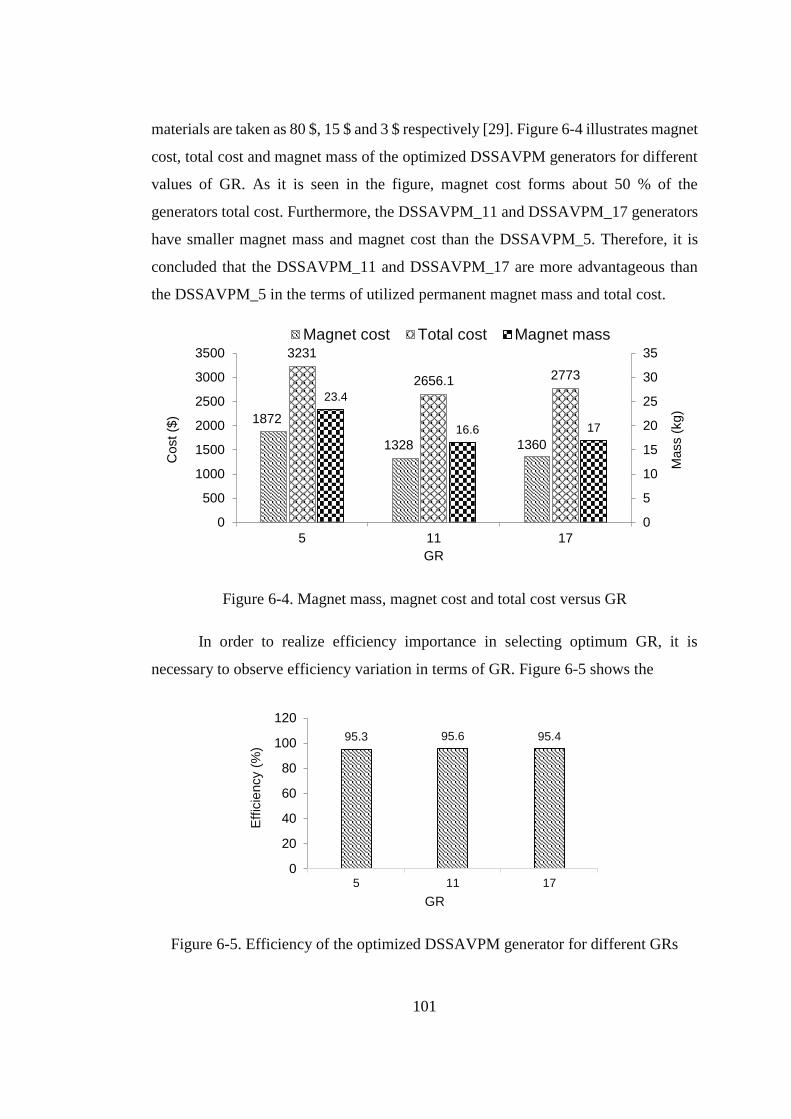
101
materials are taken as 80 $, 15 $ and 3 $ respectively [29]. Figure 6-4 illustrates magnet
cost, total cost and magnet mass of the optimized DSSAVPM generators for different
values of GR. As it is seen in the figure, magnet cost forms about 50 % of the
generators total cost. Furthermore, the DSSAVPM_11 and DSSAVPM_17 generators
have smaller magnet mass and magnet cost than the DSSAVPM_5. Therefore, it is
concluded that the DSSAVPM_11 and DSSAVPM_17 are more advantageous than
the DSSAVPM_5 in the terms of utilized permanent magnet mass and total cost.
Figure 6-4. Magnet mass, magnet cost and total cost versus GR
In order to realize efficiency importance in selecting optimum GR, it is
necessary to observe efficiency variation in terms of GR. Figure 6-5 shows the
Figure 6-5. Efficiency of the optimized DSSAVPM generator for different GRs
1872
1328 1360
3231
2656.1 2773
23.4
16.6 17
0
5
10
15
20
25
30
35
5 11 17
0
500
1000
1500
2000
2500
3000
3500
Mass (
kg)
GR
Cost ($
)
Magnet cost Total cost Magnet mass
95.3 95.6 95.4
0
20
40
60
80
100
120
5 11 17
Eff
icie
ncy (
%)
GR
102
efficiency of optimized generators for three GRs. As it is seen in the figure, there are
very small differences between the efficiencies. So efficiency cannot be a reference of
decision in optimum GR selection.
To sum up, it can be stated that the selection of optimum GR depends on
optimization criteria. The DSSAVPM_5, DSSAVPM_11 and DSSAVPM_17 have
approximately same active material mass. The DSSAVPM_5 generator has better
power factor than the DSSAVPM_11 and DSSAVPM_17 generators, while the
DSSAVPM_11 and DSSAVPM_17 have lower magnet mass and lower cost. Since
generator mass and power factor are introduced as main criteria in optimum generator
selection, the optimum GR is chosen 5 and the DSSAVPM_5 is selected as the most
optimum generator.
6.3 Active mass optimization of the RFPM generator
In this section, active-mass optimization of the RFPM generator is discussed.
The electromagnetic design and optimization procedure of RFPM generator is
presented in the chapter 5. Design constants and parameters are specified in the same
chapter, so there is no need to repeat them here. Before starting optimization, it is
necessary to allocate the penalty coefficients and GA toolbox specifications. The
values of these parameters for optimization of the RFPM generator are reported in
Table 6-3.
Table 6-3. Penalty coefficients and GA specifications for optimization of the RFPM
generator
parameter Value parameter Value
tooth width penalty factor (k1) 100000 Number of Generation 100
Axial length penalty factor (k2) 100000 Elite count 1
Tooth flux density penalty factor (k3) 10000 Crossover factor 0.9
Number of Population 100 Mutation factor 0.1
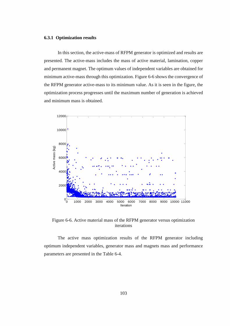
103
6.3.1 Optimization results
In this section, the active-mass of RFPM generator is optimized and results are
presented. The active-mass includes the mass of active material, lamination, copper
and permanent magnet. The optimum values of independent variables are obtained for
minimum active-mass through this optimization. Figure 6-6 shows the convergence of
the RFPM generator active-mass to its minimum value. As it is seen in the figure, the
optimization process progresses until the maximum number of generation is achieved
and minimum mass is obtained.
Figure 6-6. Active material mass of the RFPM generator versus optimization
iterations
The active mass optimization results of the RFPM generator including
optimum independent variables, generator mass and magnets mass and performance
parameters are presented in the Table 6-4.
0 1000 2000 3000 4000 5000 6000 7000 8000 9000 10000 110000
2000
4000
6000
8000
10000
12000
Iteration
Activ
e m
ass (
kg
)
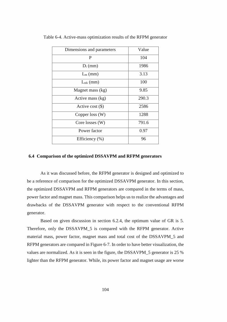
104
Table 6-4. Active-mass optimization results of the RFPM generator
Dimensions and parameters Value
P 104
Di (mm) 1986
Lm (mm) 3.13
Lstk (mm) 100
Magnet mass (kg) 9.85
Active mass (kg) 290.3
Active cost ($) 2586
Copper loss (W) 1288
Core losses (W) 791.6
Power factor 0.97
Efficiency (%) 96
6.4 Comparison of the optimized DSSAVPM and RFPM generators
As it was discussed before, the RFPM generator is designed and optimized to
be a reference of comparison for the optimized DSSAVPM generator. In this section,
the optimized DSSAVPM and RFPM generators are compared in the terms of mass,
power factor and magnet mass. This comparison helps us to realize the advantages and
drawbacks of the DSSAVPM generator with respect to the conventional RFPM
generator.
Based on given discussion in section 6.2.4, the optimum value of GR is 5.
Therefore, only the DSSAVPM_5 is compared with the RFPM generator. Active
material mass, power factor, magnet mass and total cost of the DSSAVPM_5 and
RFPM generators are compared in Figure 6-7. In order to have better visualization, the
values are normalized. As it is seen in the figure, the DSSAVPM_5 generator is 25 %
lighter than the RFPM generator. While, its power factor and magnet usage are worse
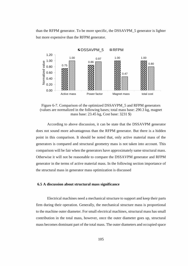
105
than the RFPM generator. To be more specific, the DSSAVPM_5 generator is lighter
but more expensive than the RFPM generator.
Figure 6-7. Comparison of the optimized DSSAVPM_5 and RFPM generators
(values are normalized in the following bases; total mass base: 290.3 kg, magnet
mass base: 23.45 kg, Cost base: 3231 $)
According to above discussion, it can be state that the DSSAVPM generator
does not sound more advantageous than the RFPM generator. But there is a hidden
point in this comparison. It should be noted that, only active material mass of the
generators is compared and structural geometry mass is not taken into account. This
comparison will be fair when the generators have approximately same structural mass.
Otherwise it will not be reasonable to compare the DSSAVPM generator and RFPM
generator in the terms of active material mass. In the following section importance of
the structural mass in generator mass optimization is discussed
6.5 A discussion about structural mass significance
Electrical machines need a mechanical structure to support and keep their parts
firm during their operation. Generally, the mechanical structure mass is proportional
to the machine outer diameter. For small electrical machines, structural mass has small
contribution in the total mass, however, once the outer diameter goes up, structural
mass becomes dominant part of the total mass. The outer diameters and occupied space
0.75
0.86
1.00 1.001.00 0.97
0.47
0.80
0.00
0.20
0.40
0.60
0.80
1.00
1.20
Active mass Power factor Magnet mass total cost
Norm
aliz
ed v
alu
e
DSSAVPM_5 RFPM
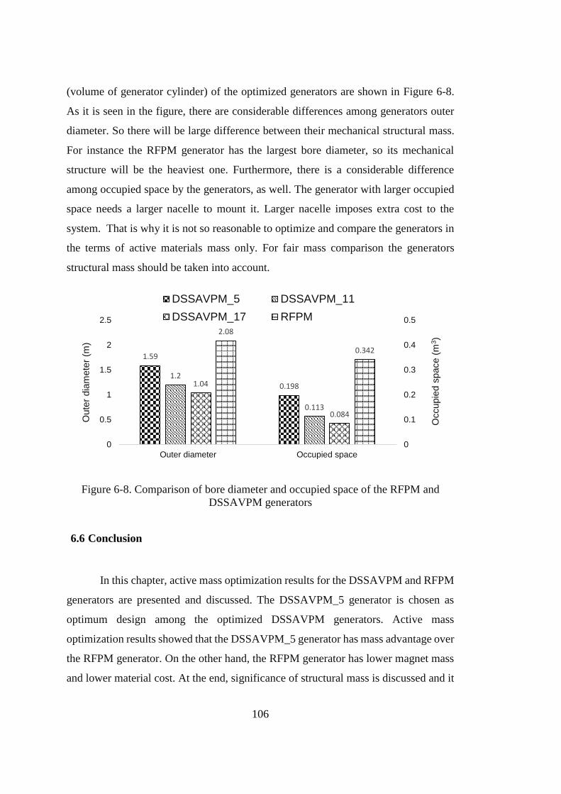
106
(volume of generator cylinder) of the optimized generators are shown in Figure 6-8.
As it is seen in the figure, there are considerable differences among generators outer
diameter. So there will be large difference between their mechanical structural mass.
For instance the RFPM generator has the largest bore diameter, so its mechanical
structure will be the heaviest one. Furthermore, there is a considerable difference
among occupied space by the generators, as well. The generator with larger occupied
space needs a larger nacelle to mount it. Larger nacelle imposes extra cost to the
system. That is why it is not so reasonable to optimize and compare the generators in
the terms of active materials mass only. For fair mass comparison the generators
structural mass should be taken into account.
Figure 6-8. Comparison of bore diameter and occupied space of the RFPM and
DSSAVPM generators
6.6 Conclusion
In this chapter, active mass optimization results for the DSSAVPM and RFPM
generators are presented and discussed. The DSSAVPM_5 generator is chosen as
optimum design among the optimized DSSAVPM generators. Active mass
optimization results showed that the DSSAVPM_5 generator has mass advantage over
the RFPM generator. On the other hand, the RFPM generator has lower magnet mass
and lower material cost. At the end, significance of structural mass is discussed and it
1.59
0.1981.2
0.113
1.04
0.084
2.08
0.342
0
0.1
0.2
0.3
0.4
0.5
0
0.5
1
1.5
2
2.5
Outer diameter Occupied space
Occupie
d s
pace (
m3)
Oute
r dia
mete
r (m
)
DSSAVPM_5 DSSAVPM_11
DSSAVPM_17 RFPM
107
concluded that it is not so realistic to compare the generators active materials mass
while their structural mass is not same. In order to have more realistic mass
comparison, it is necessary to include mechanical structure in the generators mass
optimization. In the next chapter, the mechanical structure of both the RFPM and
DSSAVPM generators are evaluated and an analytic design procedure is developed to
model mechanical structure of the mentioned generators in the terms of their
dimensions and parameters.

108
109
CHAPTER 7
INVESTIGATION OF STRUCTURAL MASS CONTRIBUTION TO
OVERALL WEIGHT OF RFPM AND DSSAVPM DIRECT DRIVE
GENERATORS
7.1 Introduction
The mass of electrical machines consists of active materials mass and inactive
materials mass. Active materials include copper, permanent magnet and magnetic core
which are used in electromagnetic design. Inactive materials are referred to the
materials used in structural geometry used as machine mechanical support. Structural
mass has small contribution in total mass in electrical machines with small bore
diameter. But, when bore diameter is increased, a rigid structure is required to keep
stator and rotor fixed, therefore structural mass gets larger and forms considerable part
of the total mass. Because of low operating speed, the direct drive wind turbine
generators have larger diameters with respect to the geared wind turbine generators.
So, direct drive generator is expected to have larger structural mass. In other words,
structural mass may have considerable contribution in the overall mass of generators
and active mass may not be an all-purpose objective function. That is why, it is
prominent to consider structural mass in generator mass optimization.
In [30], the structural geometry of RFPM, AFPM and TFPM machines are
evaluated. FEM simulations and analytic calculations are utilized to approximate
mechanical structure deflection due to normal and tangential force. Finally, an analytic
method is introduced to calculate structural mass of the PM machines in the terms of
inner and outer diameters, axial length and peak value of air gap flux density.
In this chapter, proposed relationships in [30] are utilized to design structural
geometry of the RFPM and DSSVPM generators. The RFPM generator structural
geometry is designed using the proposed method in [30]. The method is adapted to
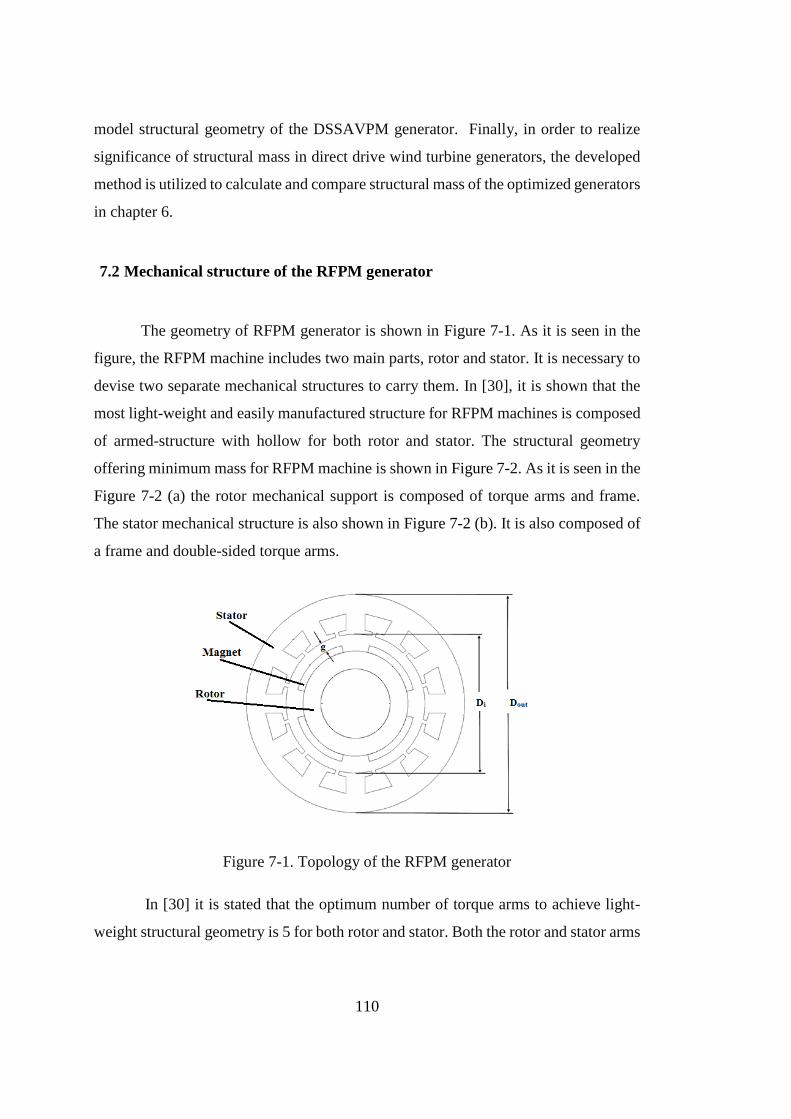
110
model structural geometry of the DSSAVPM generator. Finally, in order to realize
significance of structural mass in direct drive wind turbine generators, the developed
method is utilized to calculate and compare structural mass of the optimized generators
in chapter 6.
7.2 Mechanical structure of the RFPM generator
The geometry of RFPM generator is shown in Figure 7-1. As it is seen in the
figure, the RFPM machine includes two main parts, rotor and stator. It is necessary to
devise two separate mechanical structures to carry them. In [30], it is shown that the
most light-weight and easily manufactured structure for RFPM machines is composed
of armed-structure with hollow for both rotor and stator. The structural geometry
offering minimum mass for RFPM machine is shown in Figure 7-2. As it is seen in the
Figure 7-2 (a) the rotor mechanical support is composed of torque arms and frame.
The stator mechanical structure is also shown in Figure 7-2 (b). It is also composed of
a frame and double-sided torque arms.
Figure 7-1. Topology of the RFPM generator
In [30] it is stated that the optimum number of torque arms to achieve light-
weight structural geometry is 5 for both rotor and stator. Both the rotor and stator arms
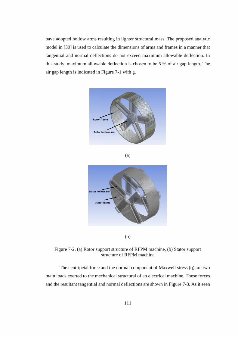
111
have adopted hollow arms resulting in lighter structural mass. The proposed analytic
model in [30] is used to calculate the dimensions of arms and frames in a manner that
tangential and normal deflections do not exceed maximum allowable deflection. In
this study, maximum allowable deflection is chosen to be 5 % of air gap length. The
air gap length is indicated in Figure 7-1 with g.
(a)
(b)
Figure 7-2. (a) Rotor support structure of RFPM machine, (b) Stator support
structure of RFPM machine
The centripetal force and the normal component of Maxwell stress (q) are two
main loads exerted to the mechanical structural of an electrical machine. These forces
and the resultant tangential and normal deflections are shown in Figure 7-3. As it seen
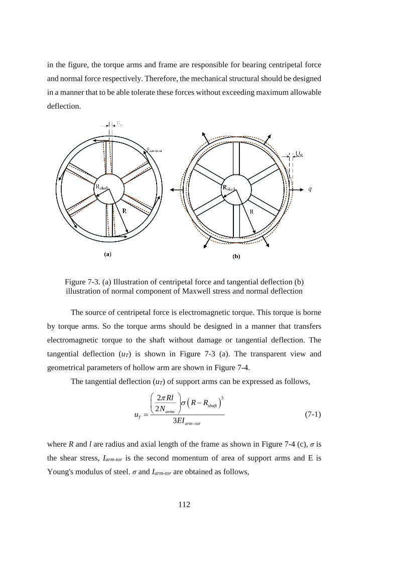
112
in the figure, the torque arms and frame are responsible for bearing centripetal force
and normal force respectively. Therefore, the mechanical structural should be designed
in a manner that to be able tolerate these forces without exceeding maximum allowable
deflection.
Figure 7-3. (a) Illustration of centripetal force and tangential deflection (b)
illustration of normal component of Maxwell stress and normal deflection
The source of centripetal force is electromagnetic torque. This torque is borne
by torque arms. So the torque arms should be designed in a manner that transfers
electromagnetic torque to the shaft without damage or tangential deflection. The
tangential deflection (uT) is shown in Figure 7-3 (a). The transparent view and
geometrical parameters of hollow arm are shown in Figure 7-4.
The tangential deflection (uT) of support arms can be expressed as follows,
32
2
3
shaft
arms
T
arm tor
RlR R
Nu
EI
(7-1)
where R and l are radius and axial length of the frame as shown in Figure 7-4 (c), σ is
the shear stress, Iarm-tor is the second momentum of area of support arms and E is
Young's modulus of steel. σ and Iarm-tor are obtained as follows,
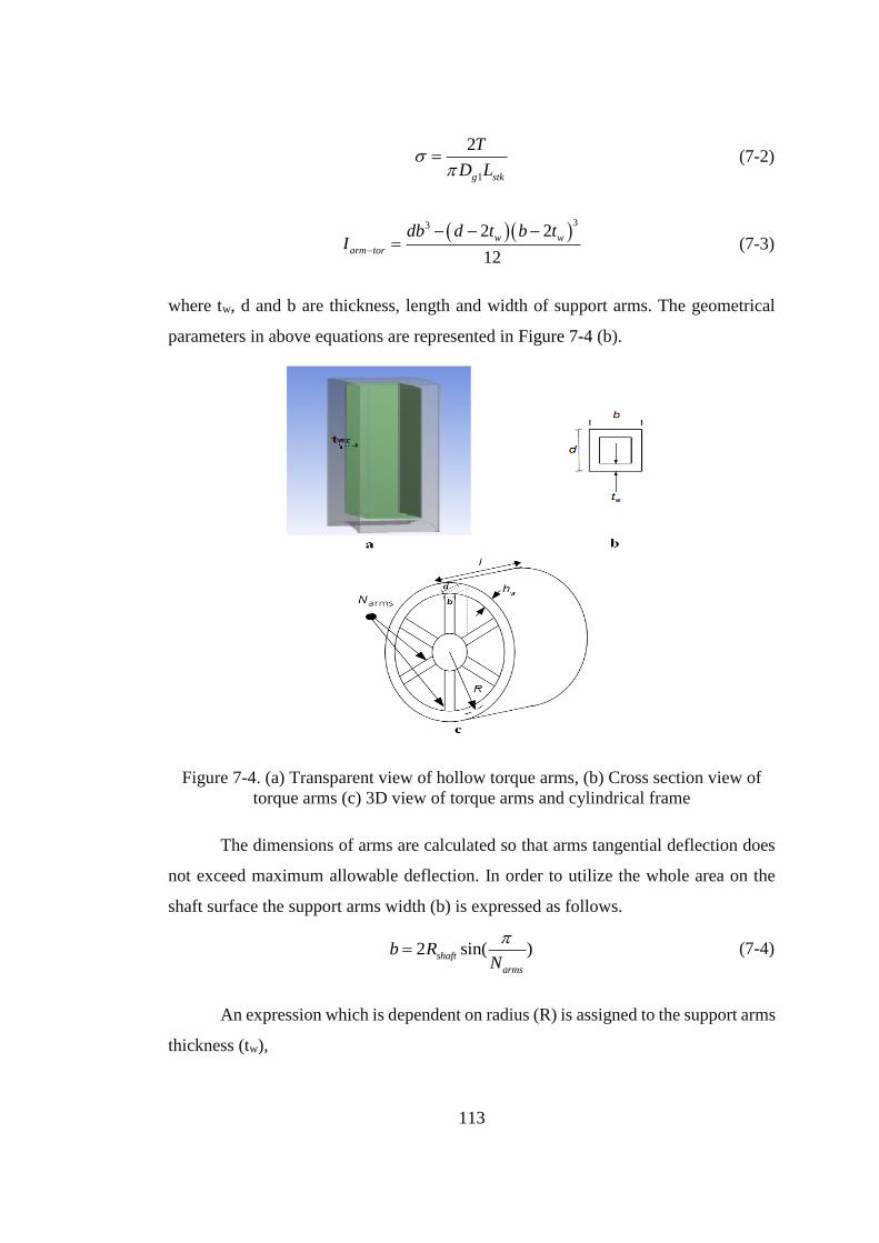
113
1
2
g stk
T
D L
(7-2)
33 2 2
12
w w
arm tor
db d t b tI
(7-3)
where tw, d and b are thickness, length and width of support arms. The geometrical
parameters in above equations are represented in Figure 7-4 (b).
Figure 7-4. (a) Transparent view of hollow torque arms, (b) Cross section view of
torque arms (c) 3D view of torque arms and cylindrical frame
The dimensions of arms are calculated so that arms tangential deflection does
not exceed maximum allowable deflection. In order to utilize the whole area on the
shaft surface the support arms width (b) is expressed as follows.
2 sin( )shaft
arms
b RN
(7-4)
An expression which is dependent on radius (R) is assigned to the support arms
thickness (tw),
114
100
w
Rt (7-5)
Now, by assigning values of b and tw, the arm length in the Z direction (d) is
calculated so that tangential deflection becomes smaller than maximum allowable
deflection which is taken as 5% of the air gap length.
The second force which should be taken into account in mechanical structure
design is Maxwell normal force. This force is indicated in Figure 7-3 (b). The normal
component of Maxwell stress q is an attraction force exerted on the rotor and stator to
close the air gap. Therefore, a frame is devised to support the rotor against Maxwell
stress. Similarly, another frame is used to support the stator against the Maxwell
normal force. The Maxwell normal force is proportional to the square of peak air gap
flux density.
2
02
g peakBq
(7-6)
where µ0 is the permeability of free space.
The Maxwell normal force and the resultant radial deflection are indicated in
Figure 3_b. The thickness of rotor and stator frames should be obtained in a manner
that normal deflection does not exceed maximum normal deflection. The analytic
equation that gives the radial deflection of the rotor and stator frames due to Maxwell
stress is expressed as follows [30].
3
2 2
3 3
sin cos 1 1
4sin 2sin 21
1 1
sin tan 4 4 2 1 2
R
y shaft
RqR
uEh R RR R R
IA I I m a
(7-7)
where Rshaft, R and hy are shaft radius, cylindrical support radius and cylindrical support
thickness respectively, θ is the half of the angle between arms (rad), I is the second
moment of area of the cylindrical frame (m4) of the rotor or stator frame, A is the cross
sectional area of the stator and rotor frame (m2) (thickness) and a is the cross area of
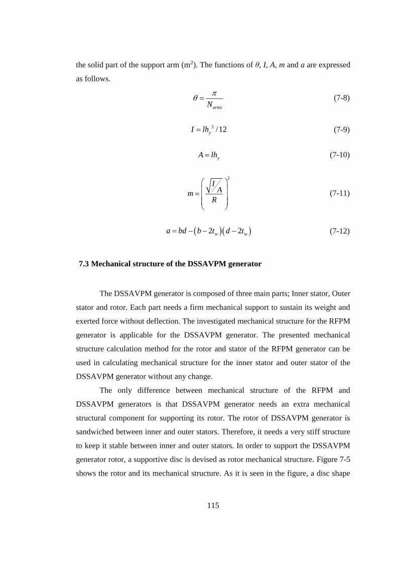
115
the solid part of the support arm (m2). The functions of θ, I, A, m and a are expressed
as follows.
armsN
(7-8)
3 /12yI lh (7-9)
yA lh (7-10)
2
IA
mR
(7-11)
2 2w wa bd b t d t (7-12)
7.3 Mechanical structure of the DSSAVPM generator
The DSSAVPM generator is composed of three main parts; Inner stator, Outer
stator and rotor. Each part needs a firm mechanical support to sustain its weight and
exerted force without deflection. The investigated mechanical structure for the RFPM
generator is applicable for the DSSAVPM generator. The presented mechanical
structure calculation method for the rotor and stator of the RFPM generator can be
used in calculating mechanical structure for the inner stator and outer stator of the
DSSAVPM generator without any change.
The only difference between mechanical structure of the RFPM and
DSSAVPM generators is that DSSAVPM generator needs an extra mechanical
structural component for supporting its rotor. The rotor of DSSAVPM generator is
sandwiched between inner and outer stators. Therefore, it needs a very stiff structure
to keep it stable between inner and outer stators. In order to support the DSSAVPM
generator rotor, a supportive disc is devised as rotor mechanical structure. Figure 7-5
shows the rotor and its mechanical structure. As it is seen in the figure, a disc shape
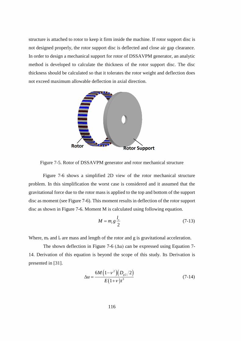
116
structure is attached to rotor to keep it firm inside the machine. If rotor support disc is
not designed properly, the rotor support disc is deflected and close air gap clearance.
In order to design a mechanical support for rotor of DSSAVPM generator, an analytic
method is developed to calculate the thickness of the rotor support disc. The disc
thickness should be calculated so that it tolerates the rotor weight and deflection does
not exceed maximum allowable deflection in axial direction.
Figure 7-5. Rotor of DSSAVPM generator and rotor mechanical structure
Figure 7-6 shows a simplified 2D view of the rotor mechanical structure
problem. In this simplification the worst case is considered and it assumed that the
gravitational force due to the rotor mass is applied to the top and bottom of the support
disc as moment (see Figure 7-6). This moment results in deflection of the rotor support
disc as shown in Figure 7-6. Moment M is calculated using following equation.
2
rr
lM m g (7-13)
Where, mr and lr are mass and length of the rotor and g is gravitational acceleration.
The shown deflection in Figure 7-6 (Δu) can be expressed using Equation 7-
14. Derivation of this equation is beyond the scope of this study. Its Derivation is
presented in [31].
2
2
3
6 1 2
1
gM Du
E t
(7-14)
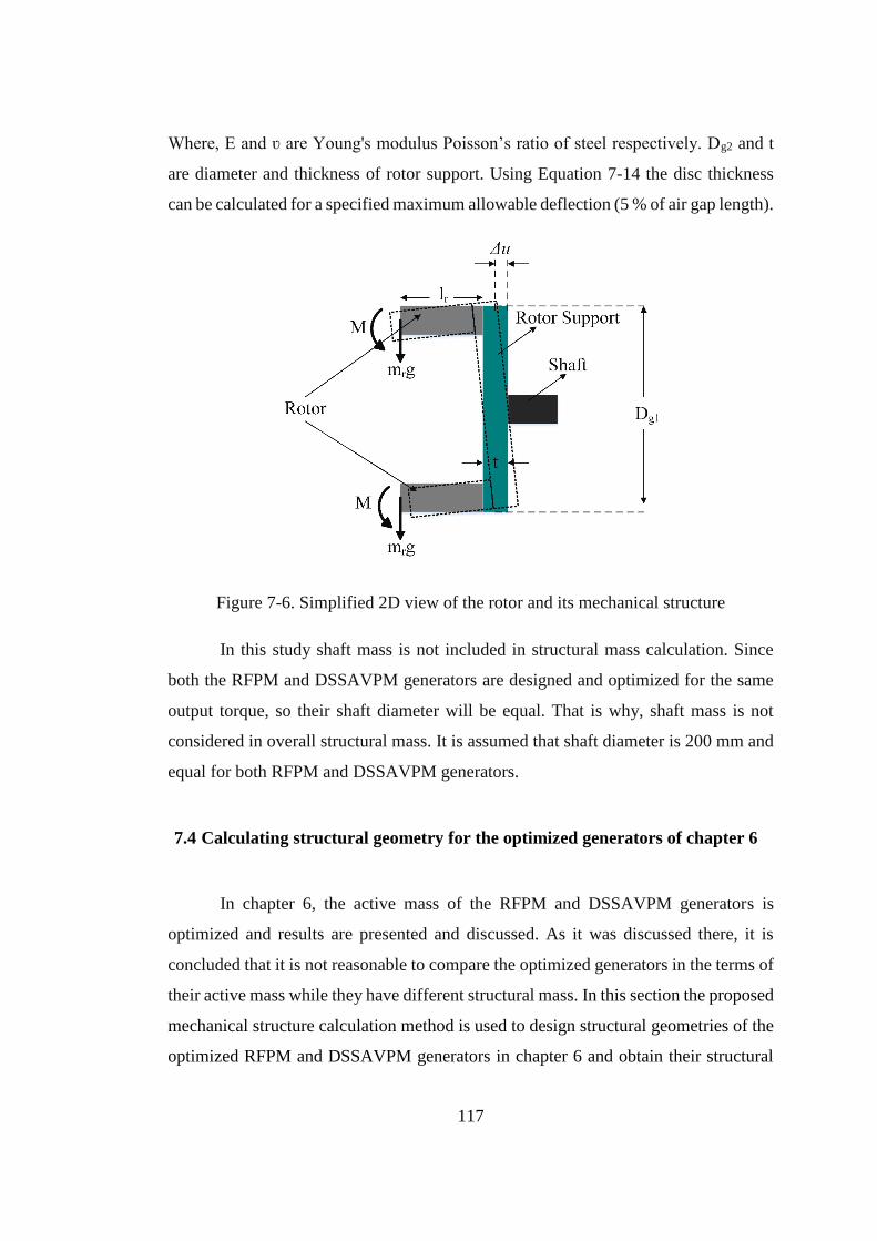
117
Where, E and ʋ are Young's modulus Poisson’s ratio of steel respectively. Dg2 and t
are diameter and thickness of rotor support. Using Equation 7-14 the disc thickness
can be calculated for a specified maximum allowable deflection (5 % of air gap length).
Figure 7-6. Simplified 2D view of the rotor and its mechanical structure
In this study shaft mass is not included in structural mass calculation. Since
both the RFPM and DSSAVPM generators are designed and optimized for the same
output torque, so their shaft diameter will be equal. That is why, shaft mass is not
considered in overall structural mass. It is assumed that shaft diameter is 200 mm and
equal for both RFPM and DSSAVPM generators.
7.4 Calculating structural geometry for the optimized generators of chapter 6
In chapter 6, the active mass of the RFPM and DSSAVPM generators is
optimized and results are presented and discussed. As it was discussed there, it is
concluded that it is not reasonable to compare the optimized generators in the terms of
their active mass while they have different structural mass. In this section the proposed
mechanical structure calculation method is used to design structural geometries of the
optimized RFPM and DSSAVPM generators in chapter 6 and obtain their structural
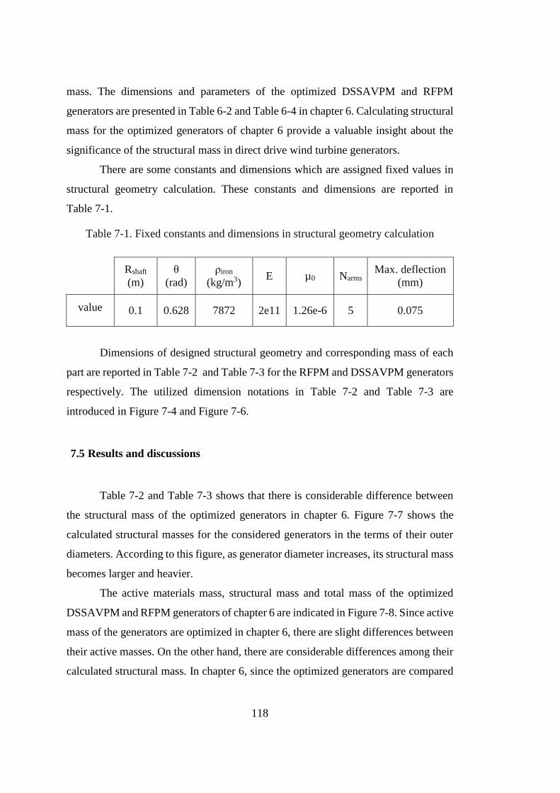
118
mass. The dimensions and parameters of the optimized DSSAVPM and RFPM
generators are presented in Table 6-2 and Table 6-4 in chapter 6. Calculating structural
mass for the optimized generators of chapter 6 provide a valuable insight about the
significance of the structural mass in direct drive wind turbine generators.
There are some constants and dimensions which are assigned fixed values in
structural geometry calculation. These constants and dimensions are reported in
Table 7-1.
Table 7-1. Fixed constants and dimensions in structural geometry calculation
Rshaft
(m)
θ
(rad)
ρiron
(kg/m3) E µ0 Narms
Max. deflection
(mm)
value 0.1 0.628 7872 2e11 1.26e-6 5 0.075
Dimensions of designed structural geometry and corresponding mass of each
part are reported in Table 7-2 and Table 7-3 for the RFPM and DSSAVPM generators
respectively. The utilized dimension notations in Table 7-2 and Table 7-3 are
introduced in Figure 7-4 and Figure 7-6.
7.5 Results and discussions
Table 7-2 and Table 7-3 shows that there is considerable difference between
the structural mass of the optimized generators in chapter 6. Figure 7-7 shows the
calculated structural masses for the considered generators in the terms of their outer
diameters. According to this figure, as generator diameter increases, its structural mass
becomes larger and heavier.
The active materials mass, structural mass and total mass of the optimized
DSSAVPM and RFPM generators of chapter 6 are indicated in Figure 7-8. Since active
mass of the generators are optimized in chapter 6, there are slight differences between
their active masses. On the other hand, there are considerable differences among their
calculated structural mass. In chapter 6, since the optimized generators are compared
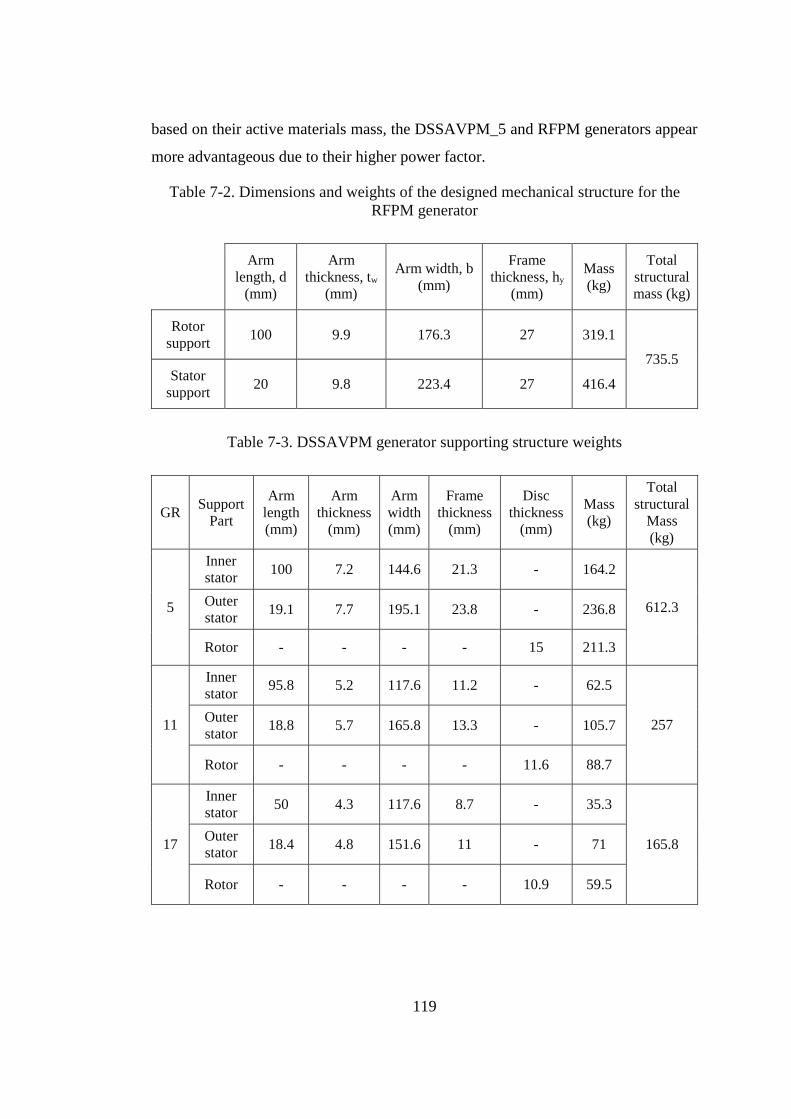
119
based on their active materials mass, the DSSAVPM_5 and RFPM generators appear
more advantageous due to their higher power factor.
Table 7-2. Dimensions and weights of the designed mechanical structure for the
RFPM generator
Arm
length, d
(mm)
Arm
thickness, tw
(mm)
Arm width, b
(mm)
Frame
thickness, hy
(mm)
Mass
(kg)
Total
structural
mass (kg)
Rotor
support 100 9.9 176.3 27 319.1
735.5 Stator
support 20 9.8 223.4 27 416.4
Table 7-3. DSSAVPM generator supporting structure weights
GR Support
Part
Arm
length
(mm)
Arm
thickness
(mm)
Arm
width
(mm)
Frame
thickness
(mm)
Disc
thickness
(mm)
Mass
(kg)
Total
structural
Mass
(kg)
5
Inner
stator 100 7.2 144.6 21.3 - 164.2
612.3 Outer
stator 19.1 7.7 195.1 23.8 - 236.8
Rotor - - - - 15 211.3
11
Inner
stator 95.8 5.2 117.6 11.2 - 62.5
257 Outer
stator 18.8 5.7 165.8 13.3 - 105.7
Rotor - - - - 11.6 88.7
17
Inner
stator 50 4.3 117.6 8.7 - 35.3
165.8 Outer
stator 18.4 4.8 151.6 11 - 71
Rotor - - - - 10.9 59.5
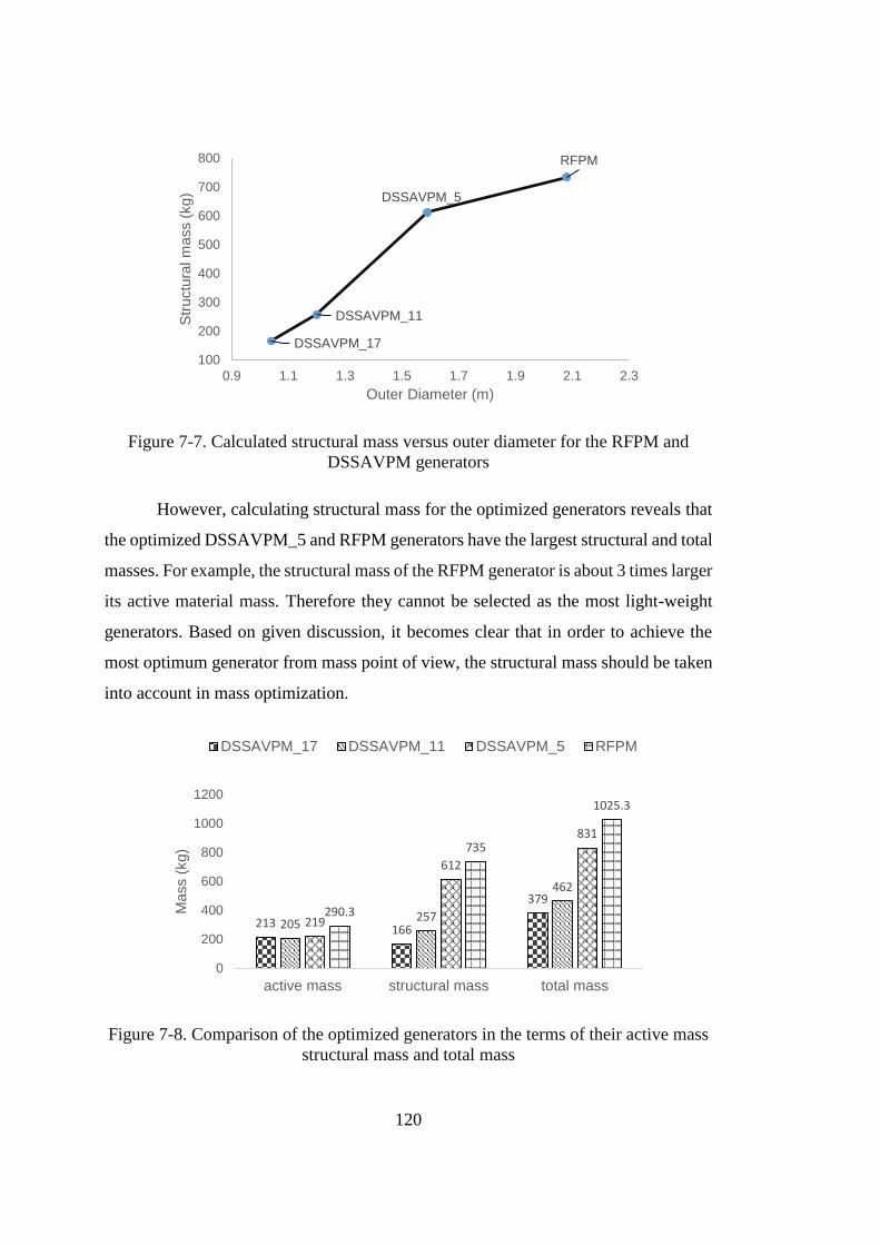
120
Figure 7-7. Calculated structural mass versus outer diameter for the RFPM and
DSSAVPM generators
However, calculating structural mass for the optimized generators reveals that
the optimized DSSAVPM_5 and RFPM generators have the largest structural and total
masses. For example, the structural mass of the RFPM generator is about 3 times larger
its active material mass. Therefore they cannot be selected as the most light-weight
generators. Based on given discussion, it becomes clear that in order to achieve the
most optimum generator from mass point of view, the structural mass should be taken
into account in mass optimization.
Figure 7-8. Comparison of the optimized generators in the terms of their active mass
structural mass and total mass
DSSAVPM_17
DSSAVPM_11
DSSAVPM_5
RFPM
100
200
300
400
500
600
700
800
0.9 1.1 1.3 1.5 1.7 1.9 2.1 2.3
Str
uctu
ral m
ass (
kg)
Outer Diameter (m)
213166
379
205257
462
219
612
831
290.3
735
1025.3
0
200
400
600
800
1000
1200
active mass structural mass total mass
Mass (
kg)
DSSAVPM_17 DSSAVPM_11 DSSAVPM_5 RFPM
121
7.6 Conclusion
In this chapter, the mechanical structure is investigated for both RFPM and
DSSAVPM generators. For this purpose the proposed mechanical structure design
method in [30] is adapted to design structural geometry of the desired generators.
Differently, an analytic model is developed to design the rotor mechanical structure in
the DSSAVPM generator.
In the next step, the presented frame structure calculation method is applied to
the optimized generators of chapter 6. The mechanical structures of the desired
generators are designed and their structural masses are obtained. The calculation
results indicate that the structural mass includes considerable part of the total mass.
Therefore, if it aimed to find the most light-weight generator, beside active materials
mass structural mass should be considered in optimizations.
In order to insert structural mass in optimization process, a MATLAB function
is written to calculate the generators structural mass in the terms of generators
parameters and geometrical dimensions using presented relationships in this chapter.
Total mass (active mass and structural mass) optimization results will be presented and
discussed in the next chapter.

122
123
CHAPTER 8
TOTAL MASS OPTIMIZATION RESULTS OF THE DSSAVPM AND RFPM
GENERATORS
8.1 Introduction
The aim of this chapter is to present total mass optimization results of the
DSSAVPM and RFPM generators. The generators total mass includes their active
materials and structural masses. The corresponding relationships for calculating active
and structural masses of the DSSAVPM and RFPM generators are presented in
previous chapters. The active mass optimizations for both of the generators are
performed and results are discussed. The generators structural mass should be included
in mass calculation for total mass optimizations. For this purpose, A MATLAB
function is written for calculating structural mass. Then it is added to the active mass
to obtain the generators total mass.
The obtained total mass function is fed to an optimization algorithm to discover
the most light-weight design for each generator. Similar to the active mass
optimization, MATLAB GA toolbox is also utilized for total mass optimization. The
constants, constraint functions and independent variables in total mass optimizations
of the DSSAVPM and RFPM generators are identical to the active mass optimizations
conditions. They are given in the chapter 4 and chapter 5 for the DSSAVPM and
RFPM generators, respectively.
In the following section, first the optimizations results of the DSSAVPM
generators are presented. Same as the active mass optimizations of the DSSAVPM
generator, the total mass optimization is performed for three GRs of 5, 11 and 17, and
the most optimum value of the GR is selected based on the specified selection criteria.
Then the total mass optimization results of the RFPM generator are given. Finally, the
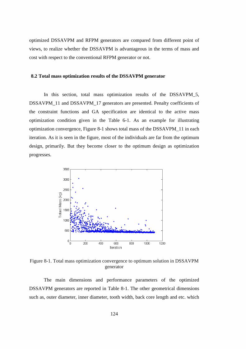
124
optimized DSSAVPM and RFPM generators are compared from different point of
views, to realize whether the DSSAVPM is advantageous in the terms of mass and
cost with respect to the conventional RFPM generator or not.
8.2 Total mass optimization results of the DSSAVPM generator
In this section, total mass optimization results of the DSSAVPM_5,
DSSAVPM_11 and DSSAVPM_17 generators are presented. Penalty coefficients of
the constraint functions and GA specification are identical to the active mass
optimization condition given in the Table 6-1. As an example for illustrating
optimization convergence, Figure 8-1 shows total mass of the DSSAVPM_11 in each
iteration. As it is seen in the figure, most of the individuals are far from the optimum
design, primarily. But they become closer to the optimum design as optimization
progresses.
Figure 8-1. Total mass optimization convergence to optimum solution in DSSAVPM
generator
The main dimensions and performance parameters of the optimized
DSSAVPM generators are reported in Table 8-1. The other geometrical dimensions
such as, outer diameter, inner diameter, tooth width, back core length and etc. which
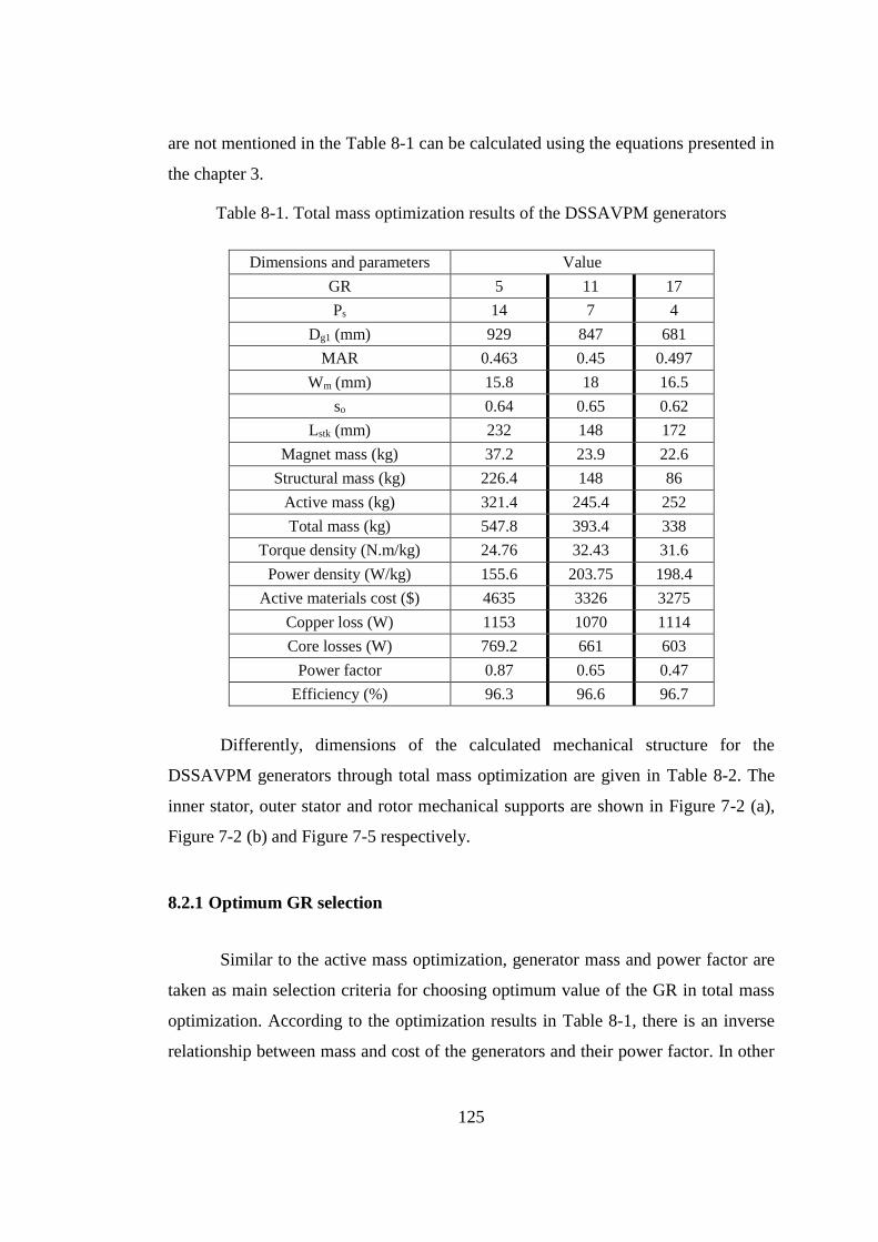
125
are not mentioned in the Table 8-1 can be calculated using the equations presented in
the chapter 3.
Table 8-1. Total mass optimization results of the DSSAVPM generators
Dimensions and parameters Value
GR 5 11 17
Ps 14 7 4
Dg1 (mm) 929 847 681
MAR 0.463 0.45 0.497
Wm (mm) 15.8 18 16.5
so 0.64 0.65 0.62
Lstk (mm) 232 148 172
Magnet mass (kg) 37.2 23.9 22.6
Structural mass (kg) 226.4 148 86
Active mass (kg) 321.4 245.4 252
Total mass (kg) 547.8 393.4 338
Torque density (N.m/kg) 24.76 32.43 31.6
Power density (W/kg) 155.6 203.75 198.4
Active materials cost ($) 4635 3326 3275
Copper loss (W) 1153 1070 1114
Core losses (W) 769.2 661 603
Power factor 0.87 0.65 0.47
Efficiency (%) 96.3 96.6 96.7
Differently, dimensions of the calculated mechanical structure for the
DSSAVPM generators through total mass optimization are given in Table 8-2. The
inner stator, outer stator and rotor mechanical supports are shown in Figure 7-2 (a),
Figure 7-2 (b) and Figure 7-5 respectively.
8.2.1 Optimum GR selection
Similar to the active mass optimization, generator mass and power factor are
taken as main selection criteria for choosing optimum value of the GR in total mass
optimization. According to the optimization results in Table 8-1, there is an inverse
relationship between mass and cost of the generators and their power factor. In other
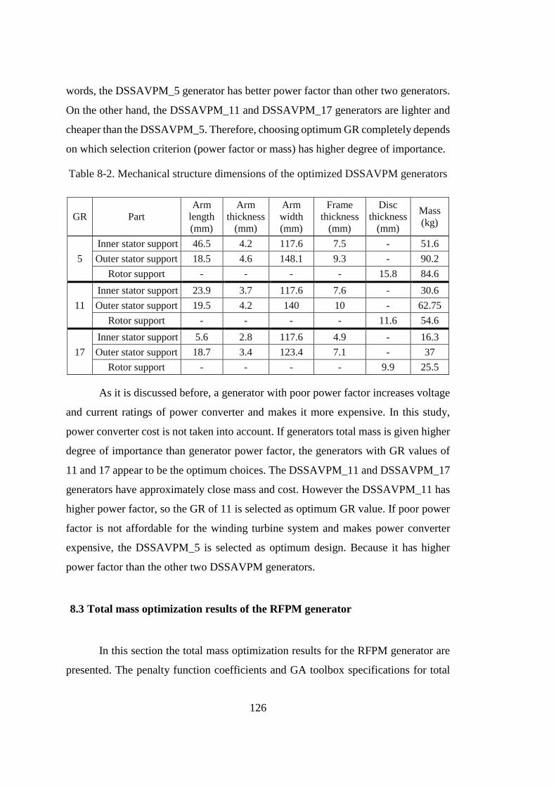
126
words, the DSSAVPM_5 generator has better power factor than other two generators.
On the other hand, the DSSAVPM_11 and DSSAVPM_17 generators are lighter and
cheaper than the DSSAVPM_5. Therefore, choosing optimum GR completely depends
on which selection criterion (power factor or mass) has higher degree of importance.
Table 8-2. Mechanical structure dimensions of the optimized DSSAVPM generators
GR Part
Arm
length
(mm)
Arm
thickness
(mm)
Arm
width
(mm)
Frame
thickness
(mm)
Disc
thickness
(mm)
Mass
(kg)
5
Inner stator support 46.5 4.2 117.6 7.5 - 51.6
Outer stator support 18.5 4.6 148.1 9.3 - 90.2
Rotor support - - - - 15.8 84.6
11
Inner stator support 23.9 3.7 117.6 7.6 - 30.6
Outer stator support 19.5 4.2 140 10 - 62.75
Rotor support - - - - 11.6 54.6
17
Inner stator support 5.6 2.8 117.6 4.9 - 16.3
Outer stator support 18.7 3.4 123.4 7.1 - 37
Rotor support - - - - 9.9 25.5
As it is discussed before, a generator with poor power factor increases voltage
and current ratings of power converter and makes it more expensive. In this study,
power converter cost is not taken into account. If generators total mass is given higher
degree of importance than generator power factor, the generators with GR values of
11 and 17 appear to be the optimum choices. The DSSAVPM_11 and DSSAVPM_17
generators have approximately close mass and cost. However the DSSAVPM_11 has
higher power factor, so the GR of 11 is selected as optimum GR value. If poor power
factor is not affordable for the winding turbine system and makes power converter
expensive, the DSSAVPM_5 is selected as optimum design. Because it has higher
power factor than the other two DSSAVPM generators.
8.3 Total mass optimization results of the RFPM generator
In this section the total mass optimization results for the RFPM generator are
presented. The penalty function coefficients and GA toolbox specifications for total
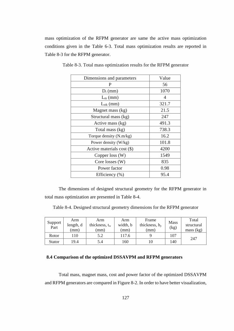
127
mass optimization of the RFPM generator are same the active mass optimization
conditions given in the Table 6-3. Total mass optimization results are reported in
Table 8-3 for the RFPM generator.
Table 8-3. Total mass optimization results for the RFPM generator
Dimensions and parameters Value
P 56
Di (mm) 1070
Lm (mm) 4
Lstk (mm) 321.7
Magnet mass (kg) 21.5
Structural mass (kg) 247
Active mass (kg) 491.3
Total mass (kg) 738.3
Torque density (N.m/kg) 16.2
Power density (W/kg) 101.8
Active materials cost ($) 4200
Copper loss (W) 1549
Core losses (W) 835
Power factor 0.98
Efficiency (%) 95.4
The dimensions of designed structural geometry for the RFPM generator in
total mass optimization are presented in Table 8-4.
Table 8-4. Designed structural geometry dimensions for the RFPM generator
Support
Part
Arm
length, d
(mm)
Arm
thickness, tw
(mm)
Arm
width, b
(mm)
Frame
thickness, hy
(mm)
Mass
(kg)
Total
structural
mass (kg)
Rotor 110 5.2 117.6 9 107 247
Stator 19.4 5.4 160 10 140
8.4 Comparison of the optimized DSSAVPM and RFPM generators
Total mass, magnet mass, cost and power factor of the optimized DSSAVPM
and RFPM generators are compared in Figure 8-2. In order to have better visualization,
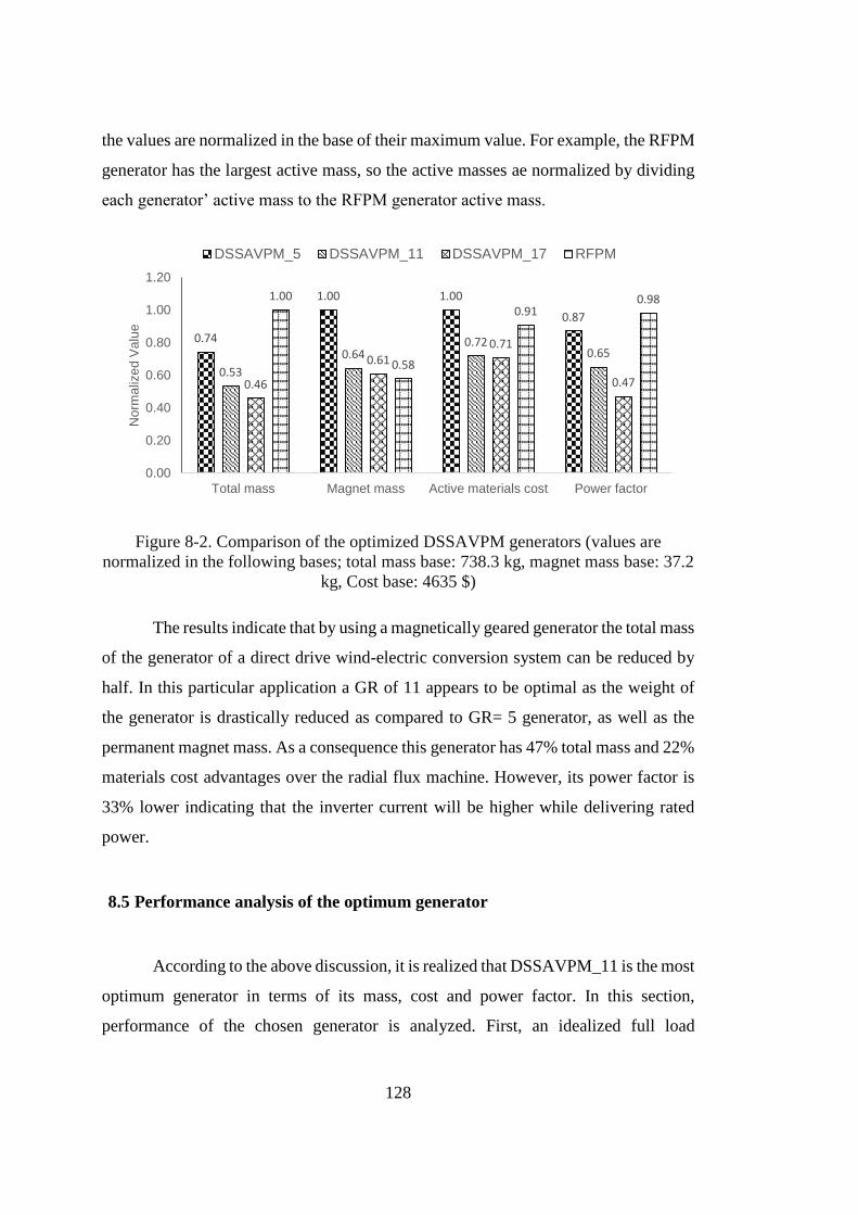
128
the values are normalized in the base of their maximum value. For example, the RFPM
generator has the largest active mass, so the active masses ae normalized by dividing
each generator’ active mass to the RFPM generator active mass.
Figure 8-2. Comparison of the optimized DSSAVPM generators (values are
normalized in the following bases; total mass base: 738.3 kg, magnet mass base: 37.2
kg, Cost base: 4635 $)
The results indicate that by using a magnetically geared generator the total mass
of the generator of a direct drive wind-electric conversion system can be reduced by
half. In this particular application a GR of 11 appears to be optimal as the weight of
the generator is drastically reduced as compared to GR= 5 generator, as well as the
permanent magnet mass. As a consequence this generator has 47% total mass and 22%
materials cost advantages over the radial flux machine. However, its power factor is
33% lower indicating that the inverter current will be higher while delivering rated
power.
8.5 Performance analysis of the optimum generator
According to the above discussion, it is realized that DSSAVPM_11 is the most
optimum generator in terms of its mass, cost and power factor. In this section,
performance of the chosen generator is analyzed. First, an idealized full load
0.74
1.00 1.00
0.87
0.53
0.640.72
0.65
0.46
0.610.71
0.47
1.00
0.58
0.910.98
0.00
0.20
0.40
0.60
0.80
1.00
1.20
Total mass Magnet mass Active materials cost Power factor
No
rma
lize
d V
alu
e
DSSAVPM_5 DSSAVPM_11 DSSAVPM_17 RFPM
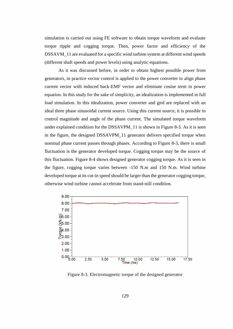
129
simulation is carried out using FE software to obtain torque waveform and evaluate
torque ripple and cogging torque. Then, power factor and efficiency of the
DSSAVM_11 are evaluated for a specific wind turbine system at different wind speeds
(different shaft speeds and power levels) using analytic equations.
As it was discussed before, in order to obtain highest possible power from
generators, in practice vector control is applied to the power converter to align phase
current vector with induced back-EMF vector and eliminate cosine term in power
equation. In this study for the sake of simplicity, an idealization is implemented in full
load simulation. In this idealization, power converter and gird are replaced with an
ideal three phase sinusoidal current source. Using this current source, it is possible to
control magnitude and angle of the phase current. The simulated torque waveform
under explained condition for the DSSAVPM_11 is shown in Figure 8-3. As it is seen
in the figure, the designed DSSAVPM_11 generator delivers specified torque when
nominal phase current passes through phases. According to Figure 8-3, there is small
fluctuation is the generator developed torque. Cogging torque may be the source of
this fluctuation. Figure 8-4 shows designed generator cogging torque. As it is seen in
the figure, cogging torque varies between -150 N.m and 150 N.m. Wind turbine
developed torque at its cut-in speed should be larger than the generator cogging torque,
otherwise wind turbine cannot accelerate from stand-still condition.
Figure 8-3. Electromagnetic torque of the designed generator
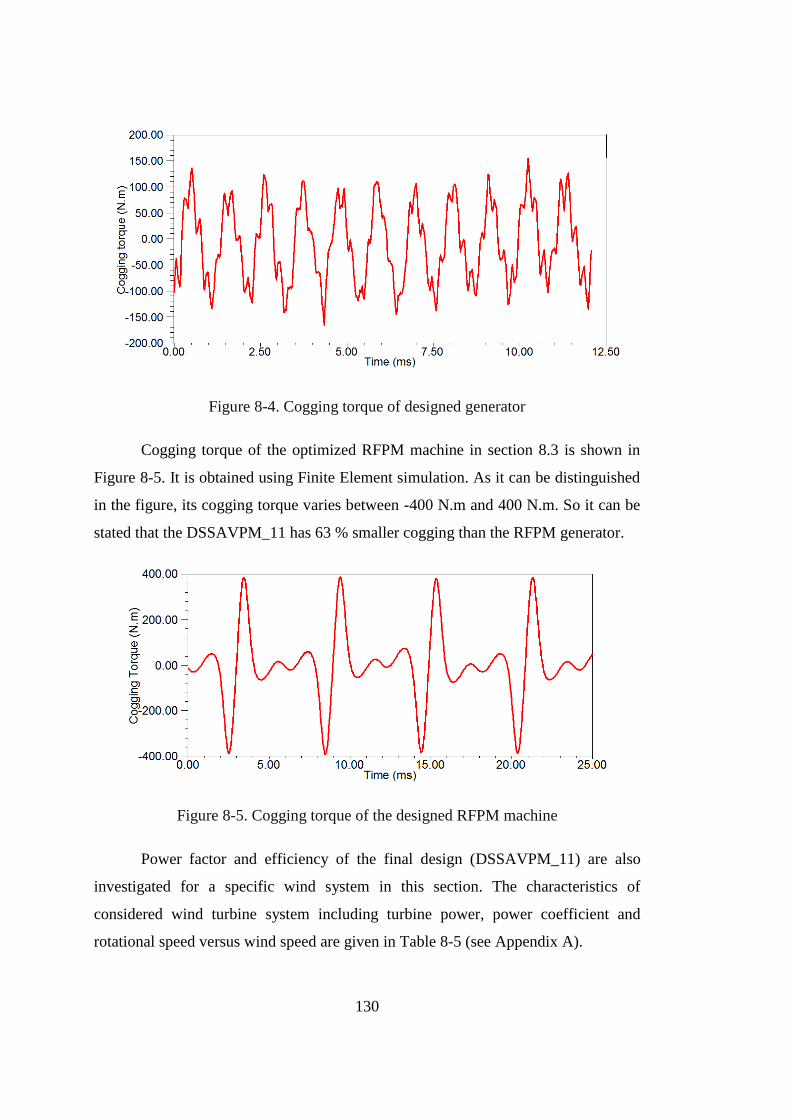
130
Figure 8-4. Cogging torque of designed generator
Cogging torque of the optimized RFPM machine in section 8.3 is shown in
Figure 8-5. It is obtained using Finite Element simulation. As it can be distinguished
in the figure, its cogging torque varies between -400 N.m and 400 N.m. So it can be
stated that the DSSAVPM_11 has 63 % smaller cogging than the RFPM generator.
Figure 8-5. Cogging torque of the designed RFPM machine
Power factor and efficiency of the final design (DSSAVPM_11) are also
investigated for a specific wind system in this section. The characteristics of
considered wind turbine system including turbine power, power coefficient and
rotational speed versus wind speed are given in Table 8-5 (see Appendix A).
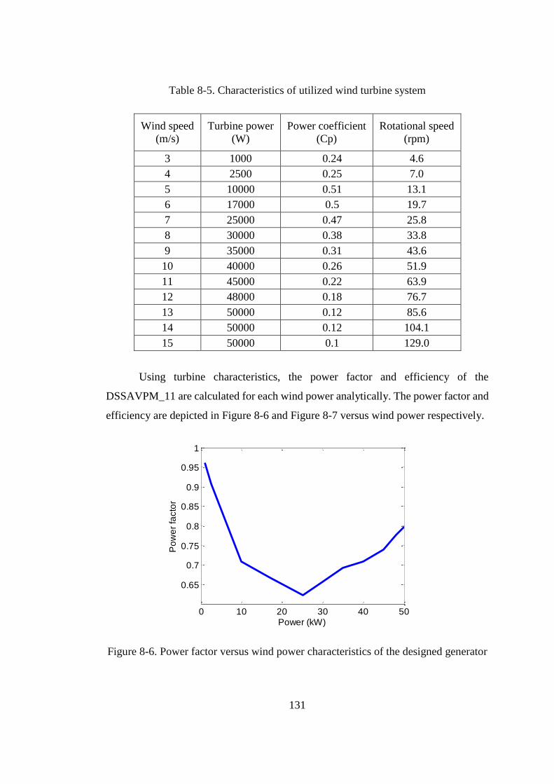
131
Table 8-5. Characteristics of utilized wind turbine system
Wind speed
(m/s)
Turbine power
(W)
Power coefficient
(Cp)
Rotational speed
(rpm)
3 1000 0.24 4.6
4 2500 0.25 7.0
5 10000 0.51 13.1
6 17000 0.5 19.7
7 25000 0.47 25.8
8 30000 0.38 33.8
9 35000 0.31 43.6
10 40000 0.26 51.9
11 45000 0.22 63.9
12 48000 0.18 76.7
13 50000 0.12 85.6
14 50000 0.12 104.1
15 50000 0.1 129.0
Using turbine characteristics, the power factor and efficiency of the
DSSAVPM_11 are calculated for each wind power analytically. The power factor and
efficiency are depicted in Figure 8-6 and Figure 8-7 versus wind power respectively.
Figure 8-6. Power factor versus wind power characteristics of the designed generator
0 10 20 30 40 50
0.65
0.7
0.75
0.8
0.85
0.9
0.95
1
Po
we
r fa
cto
r
Power (kW)
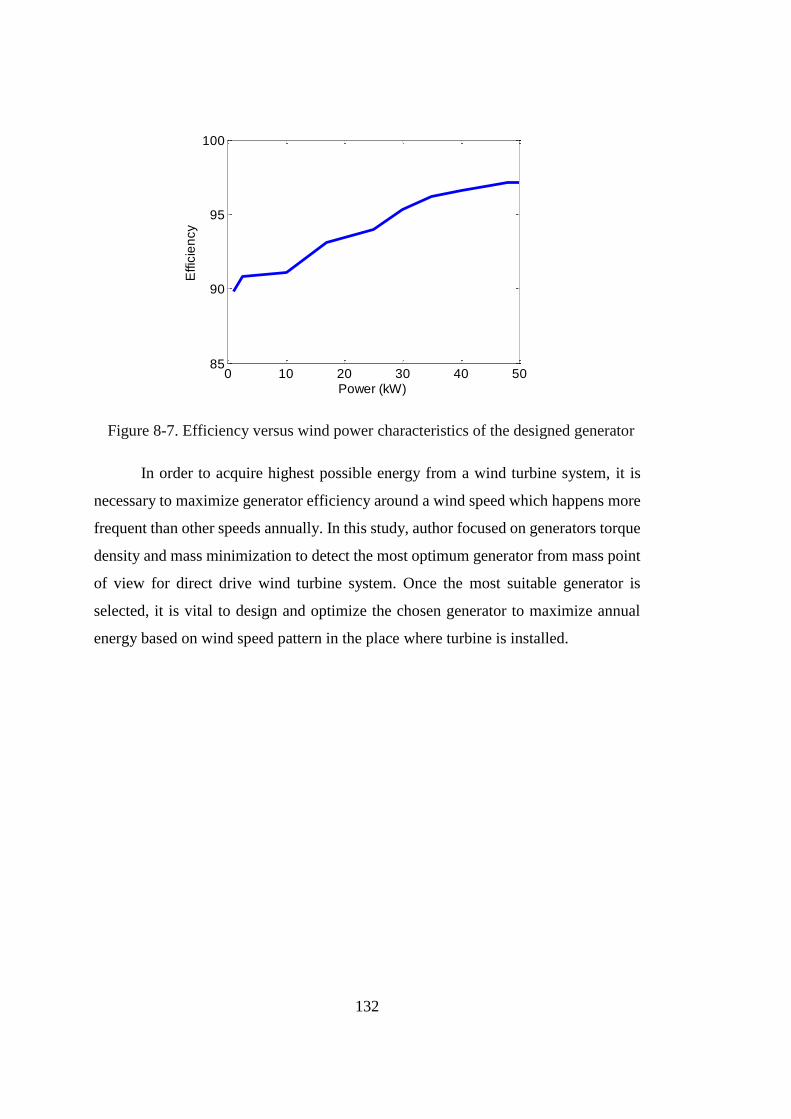
132
Figure 8-7. Efficiency versus wind power characteristics of the designed generator
In order to acquire highest possible energy from a wind turbine system, it is
necessary to maximize generator efficiency around a wind speed which happens more
frequent than other speeds annually. In this study, author focused on generators torque
density and mass minimization to detect the most optimum generator from mass point
of view for direct drive wind turbine system. Once the most suitable generator is
selected, it is vital to design and optimize the chosen generator to maximize annual
energy based on wind speed pattern in the place where turbine is installed.
0 10 20 30 40 5085
90
95
100
Effic
ien
cy
Power (kW)
133
CHAPTER 9
CONCLUSION AND FUTURE WORKS
9.1 Conclusion
The main purpose of this study is to investigate possibility of using
magnetically-geared (permanent magnet Vernier) generators for variable speed, direct
drive wind turbine applications. For this purpose, various topologies of permanent
magnet Vernier machines in the scientific literature are surveyed. Literature survey
indicates that the DSSAVPM machines offer high torque density. Furthermore, in
contrast to the other permanent magnet Vernier machines, it does not suffer from poor
power factor. Hence, the DSSAVPM machine is chosen to be designed and optimized
for a 50 kW, 60 rpm direct drive wind turbine system.
Then design procedure of the DSSAVPM generator is presented. The
developed design process is a combination of analytic and Finite Element methods.
Finite Element is utilized to estimate the average value of the fundamental air gap flux
density. In order to find the most optimum DSSAVPM generator from mass point of
view, an optimization procedure is established. The DSSAVPM generator is optimized
for three GR values namely, 5, 11 and 17.
A conventional surface-mounted RFPM generator is also designed and
optimized under the same design specifications as a comparison reference for the
DSSAVPM generator. Similar to the DSSAVPM generator, design and optimization
procedures are developed for the RFPM generator.
In the case of active mass optimizations, the DSSAVPM generator does not
seem to be more advantageous than the RFPM generator. Based on the results, the
DSSAVPM generator is lighter than the RFPM generator about 25%, while it suffers
from lower power factor, larger permanent magnet mass and higher cost. However,
134
evaluating the outer diameter and volume of the optimized generators makes it clear
that it is not a fair judgement to compare the DSSAVPM and RFPM generators in
terms of their active mass, while their structural masses are not equal. Therefore, the
need for taking structural mass into account is perceived.
In order to take structural mass into account and perform optimizations for the
generators total mass, the structural geometry of the RFPM and DSSAVPM generators
are analytically modeled in terms of their dimensions and parameters. The
optimization results show that using the DSSAVPM offers about 50% reduction in the
total mass of the direct drive wind turbine generator in comparison with the RFPM
generator. Because of lower mass and cost, the DSSAVPM_11 appears to be more
optimal than the DSSAVPM_5 in this particular application. In addition to mass
advantage, active materials cost of the DSSAVPM_11 generator is about 22% lower
than the RFPM generator. However, its power factor is 33% lower indicating that the
DSSAVPM_11 needs a power converter with larger capacity.
9.2 Future works
As future works the following complements are proposed;
Developing an analytic model to be able estimate the air gap flux
density in the DSSAVPM generator
Comparison of the optimized DSSAVPM_11 with and industrial
prototype at the same power rating
Applying the developed design and optimization procedure of the
DSSAVPM generator to a large capacity wind turbine in MW range
Designing the generator so that it is capable of generating maximum
energy for a given wind regime
Means of increasing the power factor of DSSAVPM generators need to
be studied
135
REFERENCES
[1] L. H. Hansen and L. Helle, "Conceptual survey of generators and power
electronics for wind turbines," Risø National Laboratory, Roskilde,
Denmark2001.
[2] H. Vihriala, "Control of variable speed wind turbines," PhD, Tampere
University of Technology, Hervanta, Finland, 2002.
[3] T. Ackermann, Wind power in power systems. Stockholm, sweden: John Wiley
& Sons, 2005.
[4] D. J. Bang, "Design of transverse flux permanent magnet machines for large
direct-drive wind turbines," PhD, Delft University of Technology, The
Netherlands, 2010.
[5] H. Polinder, F. F. A. van der Pijl, G. J. de Vilder, and P. J. Tavner, "Comparison
of direct-drive and geared generator concepts for wind turbines," Energy
Conversion, IEEE Transactions on, vol. 21, pp. 725-733, 2006.
[6] S. Widyan, "Design optimization, construction and test of rare-earth permanent
magnet electrical machines with new topology for wind energy applications,"
PhD, Technical University of Berlin, Berlin, Germany, 2006.
[7] M. Dubois, "Optimized permanent magnet generator topologies for direct drive
wind turbines," PhD, Delft University of Techology, The Netherlands, 2004.
[8] N. Mohan, T. M. Undeland, and W. P. Robbins, Power Electronics:
Converters, Applications, and Design: Wiley, 2002.
[9] C. Anyuan, R. Nilssen, and A. Nysveen, "Performance Comparisons Among
Radial-Flux, Multistage Axial-Flux, and Three-Phase Transverse-Flux PM
Machines for Downhole Applications," Industry Applications, IEEE
Transactions on, vol. 46, pp. 779-789, 2010.
[10] Z. Bo, T. Epskamp, M. Doppelbauer, and M. Gregor, "A comparison of the
transverse, axial and radial flux PM synchronous motors for electric vehicle,"
136
in Electric Vehicle Conference (IEVC), 2014 IEEE International, 2014, pp. 1-
6.
[11] M. R. Harris, G. H. Pajooman, and S. M. A. Sharkh, "The problem of power
factor in VRPM (transverse-flux) machines," in Electrical Machines and
Drives, 1997 Eighth International Conference on (Conf. Publ. No. 444), 1997,
pp. 386-390.
[12] L. Jian, K. T. Chau, and J. Z. Jiang, "A Magnetic-Geared Outer-Rotor
Permanent-Magnet Brushless Machine for Wind Power Generation," IEEE
Transactions on Industry Applications, vol. 45, pp. 954-962, 2009.
[13] C. H. Lee, "Vernier Motor and Its Design," IEEE Transactions on Power
Apparatus and Systems, vol. 82, pp. 343-349, 1963.
[14] D. J. Rhodes, "Assessment of vernier motor design using generalised machine
concepts," IEEE Transactions on Power Apparatus and Systems, vol. 96, pp.
1346-1352, 1977.
[15] M. R. Harris, V. Andjargholi, P. J. Lawrenson, A. Hughes, and B. Ertan,
"Vernier reluctance motor," IEE Proceedings B - Electric Power Applications,
vol. 129, pp. 43-44, 1982.
[16] G. Qishan, E. Andresen, and G. Chun, "Airgap permeance of vernier-type,
doubly-slotted magnetic structures," IEE Proceedings B - Electric Power
Applications, vol. 135, pp. 17-21, 1988.
[17] A. Ishizaki, T. Tanaka, K. Takasaki, and S. Nishikata, "Theory and optimum
design of PM Vernier motor," in Electrical Machines and Drives, 1995.
Seventh International Conference on (Conf. Publ. No. 412), 1995, pp. 208-212.
[18] A. Toba and T. A. Lipo, "Generic torque-maximizing design methodology of
surface permanent-magnet vernier machine," IEEE Transactions on Industry
Applications, vol. 36, pp. 1539-1546, 2000.
[19] J. Li, K. T. Chau, J. Z. Jiang, C. Liu, and W. Li, "A New Efficient Permanent-
Magnet Vernier Machine for Wind Power Generation," IEEE Transactions on
Magnetics, vol. 46, pp. 1475-1478, 2010.
137
[20] N. Shuangxia, S. L. Ho, and W. N. Fu, "A Novel Stator and Rotor Dual PM
Vernier Motor With Space Vector Pulse Width Modulation," IEEE
Transactions on Magnetics, vol. 50, pp. 805-808, 2014.
[21] E. Spooner and L. Haydock, "Vernier hybrid machines," IEE Proceedings -
Electric Power Applications, vol. 150, pp. 655-662, 2003.
[22] K. Atallah, J. Rens, S. Mezani, and D. Howe, "A Novel "Pseudo" ; Direct-
Drive Brushless Permanent Magnet Machine," IEEE Transactions on
Magnetics, vol. 44, pp. 4349-4352, 2008.
[23] D. Li, R. Qu, and T. A. Lipo, "High-Power-Factor Vernier Permanent-Magnet
Machines," IEEE Transactions on Industry Applications, vol. 50, pp. 3664-
3674, 2014.
[24] D. Li, R. Qu, W. Xu, J. Li, and T. A. Lipo, "Design Procedure of Dual-Stator
Spoke-Array Vernier Permanent-Magnet Machines," IEEE Transactions on
Industry Applications, vol. 51, pp. 2972-2983, 2015.
[25] M. B. B. Sharifian, K. Shaarbafi, J. Faiz, and M. R. Feyzi, "Slot fringing effect
on the magnetic characteristics of the electrical machines," in Electronics,
Circuits and Systems, 2003. ICECS 2003. Proceedings of the 2003 10th IEEE
International Conference on, 2003, pp. 778-781 Vol.2.
[26] D. Li, R. Qu, and J. Li, "Development and experimental evaluation of a single-
winding, dual-stator, spoke-array vernier permanent magnet machines," in
2015 IEEE Energy Conversion Congress and Exposition (ECCE), 2015, pp.
1885-1891.
[27] T. Weise, Global Optimization Algorithms - Theory and Application, 3rd ed.,
2011.
[28] K. Yilmaz, "Comparison of axial flux and radial flux brushless dc motor
topologies for control moment gyroscope wheel applications," Master of
Science, ELECTRICAL AND ELECTRONICS ENGINEERING, MIDDLE
EAST TECHNICAL UNIVERSITY, 2009.
[29] A. Daghigh, H. Javadi, and H. Torkaman, "Design Optimization of Direct-
Coupled Ironless Axial Flux Permanent Magnet Synchronous Wind Generator
138
with Low Cost and High Annual Energy Yield," IEEE Transactions on
Magnetics, vol. PP, pp. 1-1, 2016.
[30] A. Zavvos, "Structural Optimisation of Permanent Magnet Direct Drive
Generators for 5MW Wind Turbines," Phd dissertation, University of
Edinburgh, 2013.
[31] S. Timoshenko and S. Woinowsky-krieger, Theory of Plates and Shells,
Second ed.: McGRAW-HILL, 1987.
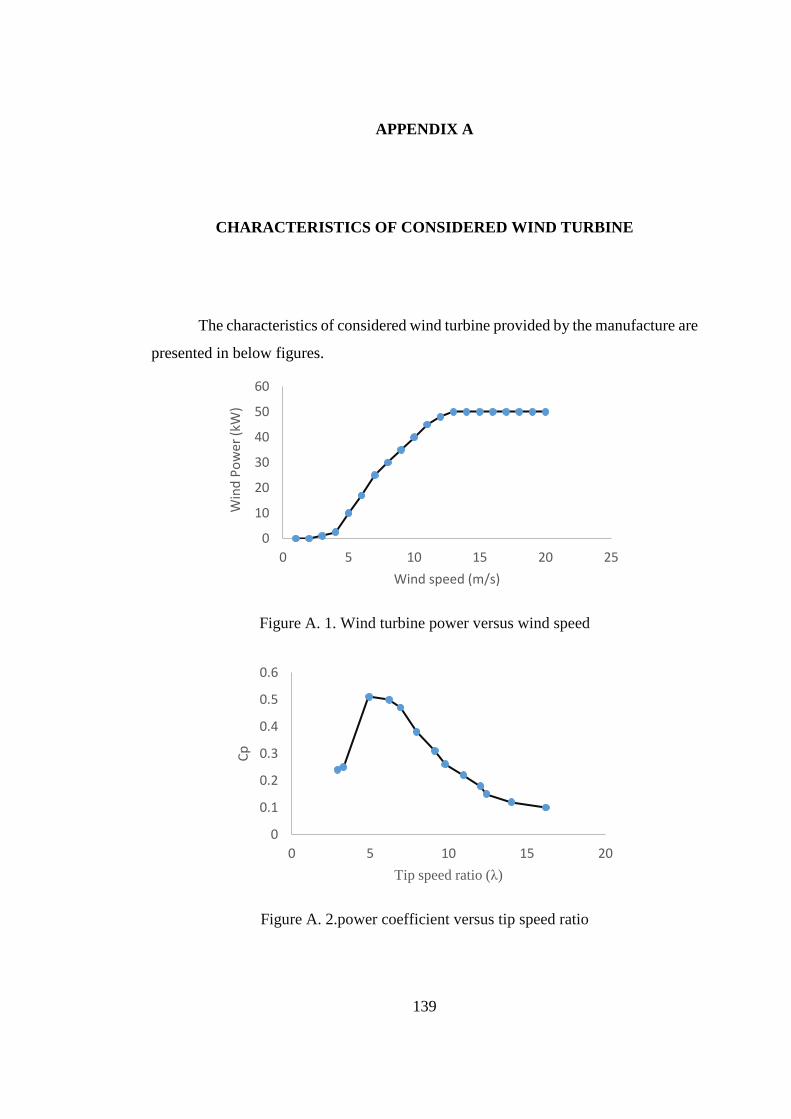
139
APPENDIX A
CHARACTERISTICS OF CONSIDERED WIND TURBINE
The characteristics of considered wind turbine provided by the manufacture are
presented in below figures.
Figure A. 1. Wind turbine power versus wind speed
Figure A. 2.power coefficient versus tip speed ratio
0
10
20
30
40
50
60
0 5 10 15 20 25
Win
d P
ow
er
(kW
)
Wind speed (m/s)
0
0.1
0.2
0.3
0.4
0.5
0.6
0 5 10 15 20
Cp
Tip speed ratio (λ)
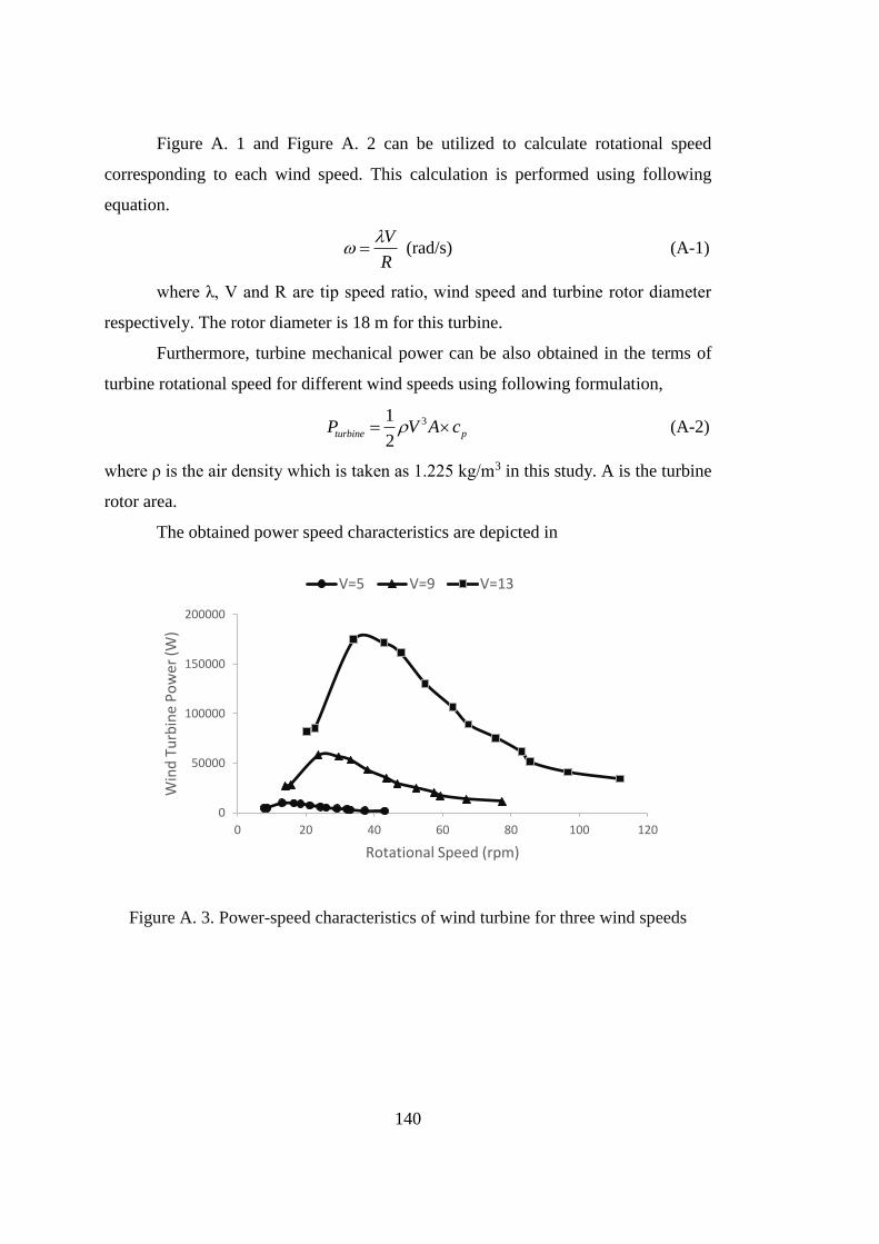
140
Figure A. 1 and Figure A. 2 can be utilized to calculate rotational speed
corresponding to each wind speed. This calculation is performed using following
equation.
V
R
(rad/s) (A-1)
where λ, V and R are tip speed ratio, wind speed and turbine rotor diameter
respectively. The rotor diameter is 18 m for this turbine.
Furthermore, turbine mechanical power can be also obtained in the terms of
turbine rotational speed for different wind speeds using following formulation,
31
2turbine pP V A c (A-2)
where ρ is the air density which is taken as 1.225 kg/m3 in this study. A is the turbine
rotor area.
The obtained power speed characteristics are depicted in
Figure A. 3. Power-speed characteristics of wind turbine for three wind speeds
0
50000
100000
150000
200000
0 20 40 60 80 100 120
Win
d T
urb
ine
Po
we
r (W
)
Rotational Speed (rpm)
V=5 V=9 V=13


![[Yasmina Reza] Art(BookFi.org)](https://img.pdfslide.us/doc/110x75/55cf97ce550346d03393bc9c/yasmina-reza-artbookfiorg.jpg)