Embed Size (px)
Citation preview
International Journal of Current Engineering and Technology E-ISSN 2277 – 4106, P-ISSN 2347 – 5161 ©2017 INPRESSCO®, All Rights Reserved Available at http://inpressco.com/category/ijcet
Research Article
1835| International Journal of Current Engineering and Technology, Vol.7, No.5 (Sept/Oct 2017)
Design and Optimization of Printed Spiral Coils used in Wireless Power Transmission Systems for Powering 10 mm2 Receiver Size at 13.56 MHz Operating Frequency Ahmed S. Ezzulddin and Ahmed A. Ibraheem* Department of Electrical Engineering, University of Technology, Baghdad- Iraq
Received 14 Aug 2017, Accepted 01 Oct 2017, Available online 08 Oct 2017, Vol.7, No.5 (Sept/Oct 2017)
Abstract Due to size limitations and limited battery life, many implant biomedical devices need to be powered inductively. This paper introduces a small size and efficient spiral square coils at 13.56 MHz to be used for bio-implantable devices. We applied our design methodology with theoretical closed-form equations using MATLAB to optimize the wireless link of a 10 mm2 implantable device example with 10 mm relative distance. The results showed that optimized coil pairs achieved 73.46% efficiency at face to face relative distance of 10 mm in the air. All results are validated with the simulation using an electromagnetic field solver HFSS 14.1. Keywords: Wireless power transfer, inductive coupling, implant biomedical devices, printed spiral coil. 1. Introduction
1 Wireless power transfer (WPT) via inductively coupled coils has triggered a great interest of research, related to its wide collection of applications, such as wireless power transfer to desktop peripheral (P. Meyer, P. Germano, M. Markovic, & Y. Perriard, 2011), contactless battery charger (E. Waffenschmidt, 2011, H. Marques & B. Borges, 2011), and implanted biomedical devices (U. Jow & M. Ghovanloo, 2007, U. Jow & M. Ghovanloo, 2009, W. Wu and Q. Fang, 2011, S. Mutashar, M. A. Hannan, S. A. Samad, & A. Hussain, 2014 , S. Stocklin, T. Volk, A. Yousaf, J. Albesa & L. Reindl, 2015, S. Mehri, A. C. Ammari, J. Ben, H. Slama, & H. Rmili , 2016, C. Yang, C. Chang, S. Lee, S. Chang, & L. Chiou , 2017). The use of a wireless inductive link to transfer power and data to implanted microsystems devices is raising. The main design interest in the implantable devices field is to reduce the patient discomfort and hazard of infection. Usually, implanted devices are obtaining power using implanted batteries, cause chemical burns and risks. Because of the chemical side effect of the implanted and its limited lifetime, researchers have developed an appropriate substitute method for powering implanted devices using inductively coupled power link. It believed that the inductive link approach is the most favorable technique for implanted devices. Its advantages ensure continuous availability of enough levels of power to the
*Corresponding author’s ORCID ID: 0000-0003-1835-4862
implanted devices. In addition, WPT can be used for a long time and within the patient’s activities. Implanted biomedical devices designed with size as small as possible to be implanted based on human biological tissues functional depth, which is typically less than 10 mm. In general, implanted microsystem stimulators need depth (1–4) mm, for cochlear implant depth is (3–6) mm and retinal implant it is 5 mm, respectively (G. M. Clark, 2003, M. S. Humayun et al., 2003). The WPT inductive coupling link consists of transmitter and receiver coils, acting as two RLC circuits. To obtain maximum power transmission efficiency, both coils circuits are tuned at the same resonant frequency . The transmitter side uses a serial-tuned to provide the low impedance to the driven side and the receiver side uses parallel with better drive non-linear rectifier loads (L. Chen, S. Liu, Y. C. Zhou, & T. J. Cui, 2013). The coupling distance between the transmitter and receiver coils is to be less than the wavelength within the near-field, which depends on the coils dimensions. Hence, the coils dimensions have a direct impact on the distance and a coupling link, which consists of two same sized or differing coils, oriented face to face. The receiver coil placed within the human body should be smallest possible size whereas; the transmitter coil can be set with flexibility in the design in term of size since it placed outside the body.
The biggest power loss typically happens in the transmitter coil parasitic resistance followed by and the power load condition within on the
Ahmed S. Ezzulddin and Ahmed A. Ibraheem Design and Optimization of Printed Spiral Coils used in Wireless Power Transmission Systems..
1836| International Journal of Current Engineering and Technology, Vol.7, No.5 (Sept/Oct 2017)
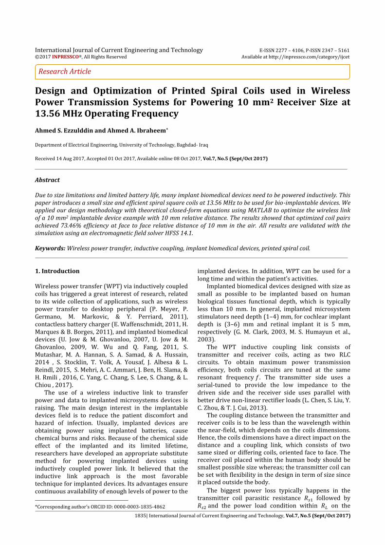
receiver side. The latter deemed to be more influential because it is surrounded by the tissue (G. Lazzi, 2005). There is also power loss within the external source, which typically represents an efficient class-E power amplifier. If the operation frequency is chosen below 20 MHz, the power loss within the surrounding tissue can be ignored (S. Stocklin, T. Volk, A. Yousaf, J. Albesa & L. Reindl , 2015, P. Vaillancourt, A. Djemouai, J. F. Harvey & M. Sawan, 1997). We choose 13.56 MHz ISM band which compatible with RFID standards (K. Finkenzeller, 2010). The overall power transmission efficiency is often dominated by efficiency link between transmitter and receiver which we will focus during the rest of this paper. The power transfer efficiency is dependent on the coupling coefficient ( ) between the transmitter and receiver coils, and the quality factors of the coils. So, to achieve high power transmission efficiency, these parameters of the link should be as high as possible. Recently, using a printed spiral coil (PSC) in inductive coupling links has got a considerably of attention. In comparison with wire-wound coils, this type of coils has an advantage from a planar structure which makes them more suitable for implanted systems located underneath the skin or within the epidural space. Furthermore, PSCs can be easily manufactured by standard fabrication technologies. In this paper, optimal printed spiral coil pair used in wireless power transfer system for implanted bio-medical devices is proposed, with external coil dimension = 32 mm and = 6 mm and implant coil dimension = 10 mm and = 5 mm by printed on FR4 substrate to achieve coupling distance 10 mm using industrial, scientific and medical (ISM) band operating frequency 13.56 MHz. 2. Theoretical Model of Printed Spiral Coil (PSC) Printed spiral coil (PSC) with its equivalent lumped elements are shown in Fig. 1 consist of inductance ( , series parasitic resistance , and parallel parasitic capacitance , these parameters affected by various
geometries, such as inner diameter , outer diameter , number of turns ( ), line width ( and track separation of copper line. The following physical expressions illustrate the relationship between the PSC geometries and its equivalent circuit parameters values.
A. Self-inductance Numerous closed-form equations propositioned to estimate the inductance in PSC. The inductance of square PSC is shown in Fig. 1(a) can be calculated from (1) given in (S. S. Mohan, M. del Mar Hershenson, S. P. Boyd, & T. H. Lee, 1999). In this paper, all PSCs design are square-shaped with rounded corners to eliminate sharp edges
(1)
where µ = is the relative permeability of space and the conductor, is the number of turns, is the average diameter of the coil,
and is the fill factor.
(a) (b) Fig. 1: (a) Geometrical parameters of a square shaped
PSC. (b) The equivalent circuit of PSC B. Series-resistance To find the parasitic DC resistance for the PSC, we need to know the total length of the conductive line , conductive material resistivity , and it’s thickness
(2)
(3)
where is line width and track separation. At high frequencies, the ac resistance after taking into account the skin effect can be approximated as (U. Jow & M. Ghovanloo, 2007).
⁄ (4)
√
(5)
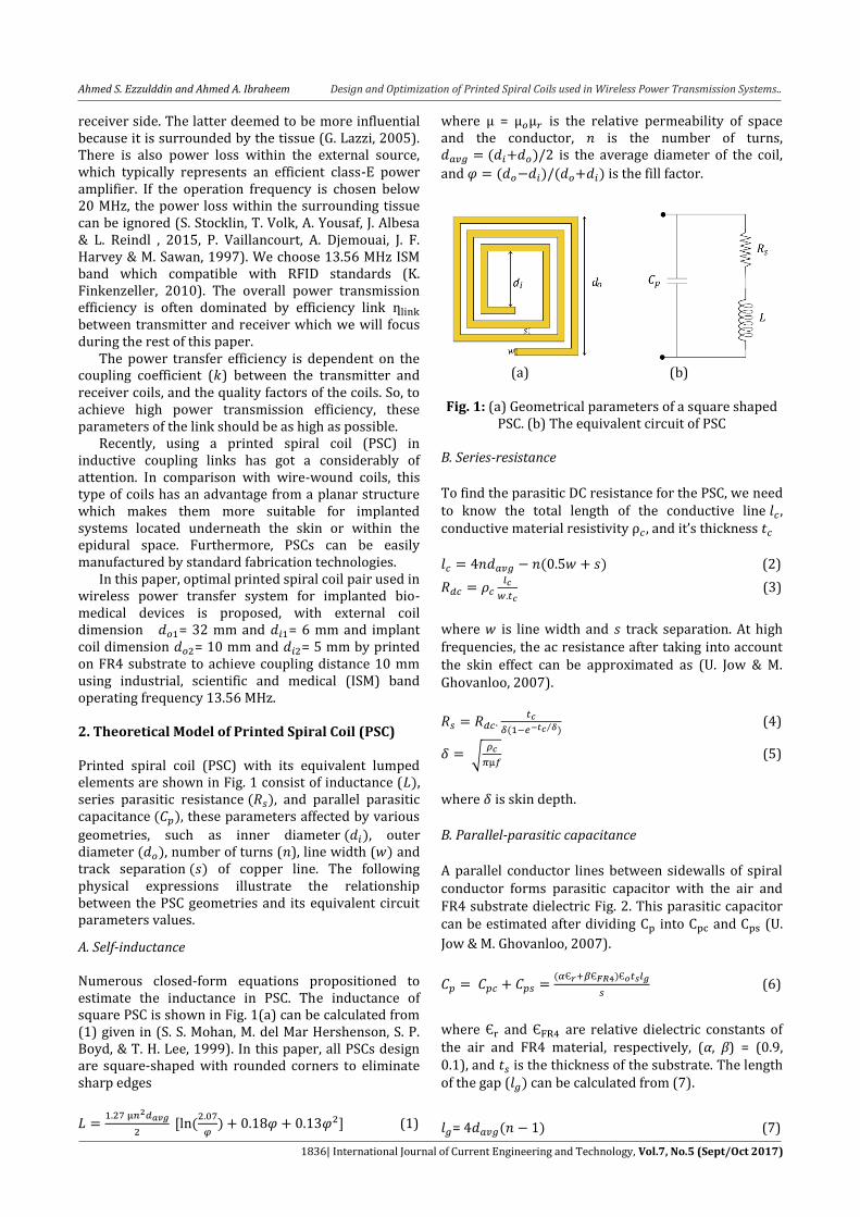
where is skin depth. B. Parallel-parasitic capacitance A parallel conductor lines between sidewalls of spiral conductor forms parasitic capacitor with the air and FR4 substrate dielectric Fig. 2. This parasitic capacitor can be estimated after dividing into and (U.
Jow & M. Ghovanloo, 2007).
(6)
where and are relative dielectric constants of the air and FR4 material, respectively, (α, β) = (0.9, 0.1), and is the thickness of the substrate. The length of the gap ( can be calculated from (7).
= (7)
Ahmed S. Ezzulddin and Ahmed A. Ibraheem Design and Optimization of Printed Spiral Coils used in Wireless Power Transmission Systems..
1837| International Journal of Current Engineering and Technology, Vol.7, No.5 (Sept/Oct 2017)
Fig. 2: The cross section of parallel conductor lines showing the parasitic capacitor within the air and
substrate
C. PSC quality factor
The quality factor is defined as
where is the
overall impedance of the model. Since is in series with and is in parallel with both (see Fig1. (b)) (U.
Jow & M. Ghovanloo, 2007). This result in (8) and (9)
(8)
. (9)
Quality factor can be approached as ⁄ intended for small or low frequency.
D. Mutual Inductance and Power Transfer Efficiency Printed spiral coils have different forms, line width, line separation, and turn numbers. These are the essential geometric parameters to determine between the PSCs. The outer radii are and , and the number of turns and . The line widths are defined as and and and are track separations for the primary and secondary PSCs, respectively. To determine the between the PSCs, it is a necessity to find all of the possible combinations of by assuming each turn as a rectangular line. And finally, total can be determined by adding all these combinations of . For different axial distance, the equation can be expressed as (S. Raju, R. Wu, M. Chan, and C. P. Yue, 2014).
(
) ∑ ∑
(10)
and
⁄ (
) (11)
where ⁄ ,
( ) ⁄ ,
(
)⁄ , ⁄ , and is
relative distance between coils.
Fig. 3 is clearly elucidated an equivalent circuit diagram of wireless power transfer WPT link. and are the inductance of the primary and secondary PSCs, respectively. is typically driven by class E amplifier
which has need of only a single transistor switch and has the benefit of high efficiency. and are the
parasitic capacitance and resistance of PSCs, respectively. and are tuning capacitors added to PSCs to make the transmitter and receiver resonate on the same frequency. Using , and , the coupling coefficient of the two coil which is the key factor in power transmission efficiency and can be found from (12).
√ (12)
Fig. 3: Equivalent circuit diagram of WPT link
In practice, the secondary coil loaded by some electrical loads such as voltage regulator and rectifier. These loads are epitomized by load resistance . At different loading condition, Power transfer efficiency link can be calculated after introduce loaded quality factor as (S. Raju, C. C. Parawoto, M. Chan, & C. P. Yue, 2015) (13)
(
) (14)
Maximum power transfer efficiency can be determined as
( √ ) (15)
In PSCs, most above-mentioned parameters are
associated. For instance, increasing for each coil
without changing can increase and . As well, it
may decrease by increasing as a result of
increased and reduced . So, there is optimal PSCs
geometry that would maximize efficiency. Other
parameters, like eddy current and substrate loss, also
be part of the cause, which are not involved in detail
due to their small effects.
3. Optimization of Printed Spiral Coils
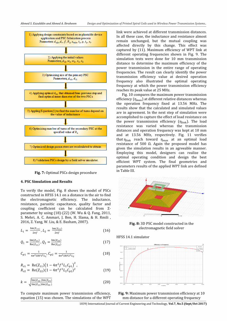
A design procedure has been represented in this part
which starts with a set of initial values and design
constraints imposed by the application and fabrication
process of the PSC and ends with the optimal PSC pair
geometries that maximize efficiency. MATLAB
simulation has been used for fine tuning the values
based on a theoretical calculation by sweeping many
parameters involved in (1)-(15).
Ahmed S. Ezzulddin and Ahmed A. Ibraheem Design and Optimization of Printed Spiral Coils used in Wireless Power Transmission Systems..
1838| International Journal of Current Engineering and Technology, Vol.7, No.5 (Sept/Oct 2017)
Biomedical application place a lower limit on the
distance between two coils and upper limit on the size
of the coil receiver ( ), which is typically implanted
in the body. We have designated the size of the
implanted to be 10 10 mm2. The coupling distance
between the PSCs ( ) is considered 10 mm. The
choice of the optimum operation frequency depends on
efficiency, size, and absorption. If the operating
frequency of power carrier is below 20 MHz, the power
loss within a human tissue can be low. A 13.56 MHz
ISM band which compatible with RFID standards has
been chosen. Table I shows the initial values and
design constraints decreed by the application and
fabrication process technology.
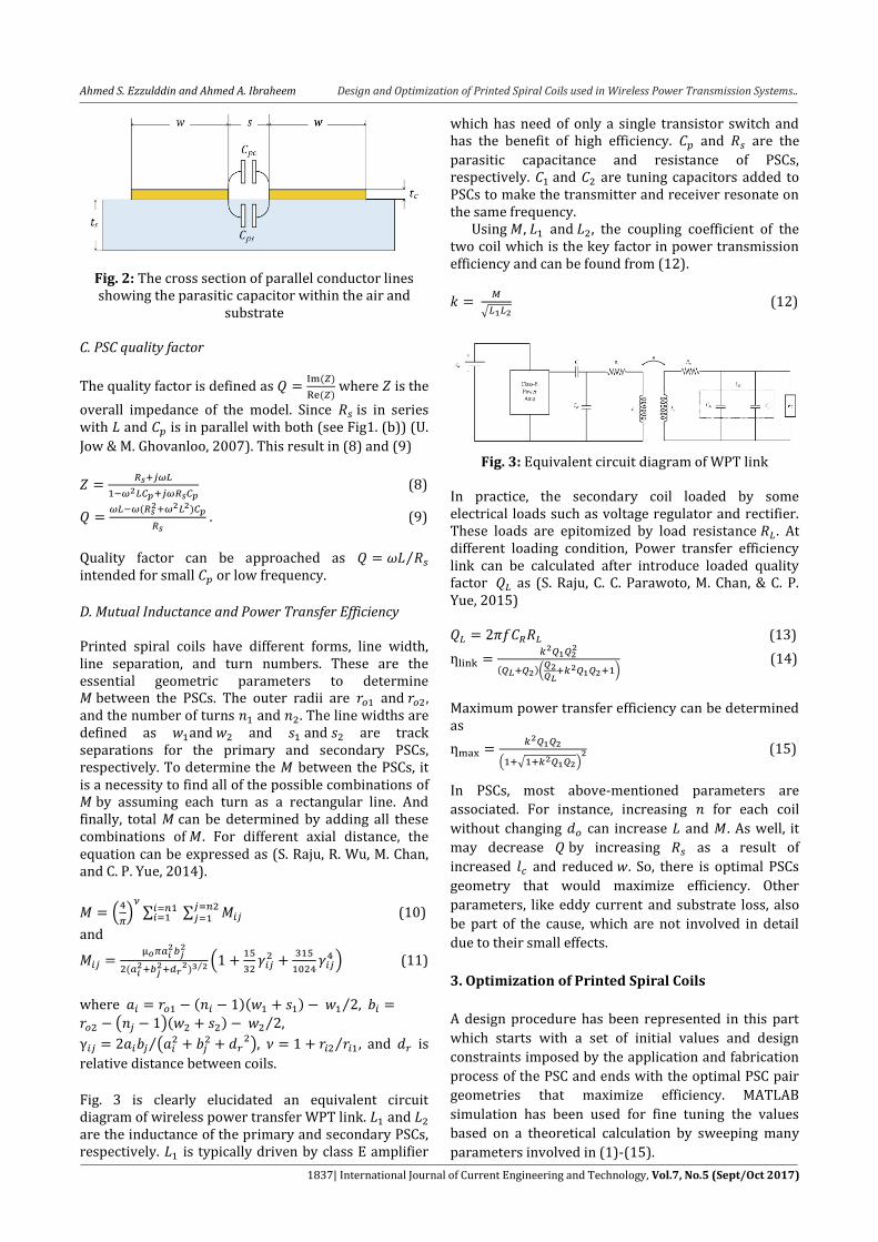
The best select for would be 32 mm with
smallest possible as illustrated in Fig. 4. Again by
fixing at 32 mm, Fig. 5 show the optimal
between 6 mm to 7 mm. Our chosen value = 6 mm,
so that the magnetic field is not dispensed, and = 5
mm to allow us to achieve a higher inductance and
higher quality factor.
Like many previous designers (S. Stocklin, T. Volk,
A. Yousaf, J. Albesa & L. Reindl, 2015, R. R. Harrison,
2007), we use a class-E amplifier to drive the coil,
suitable to be used in biomedical implantable devices
which is usually have a small load resistor due to
inductive powering (S. M. Abbas, M. A. Hannan, & A. S.
Salina, 2012). This will restrict according to
transmitted coil inductance captured by (1). To find
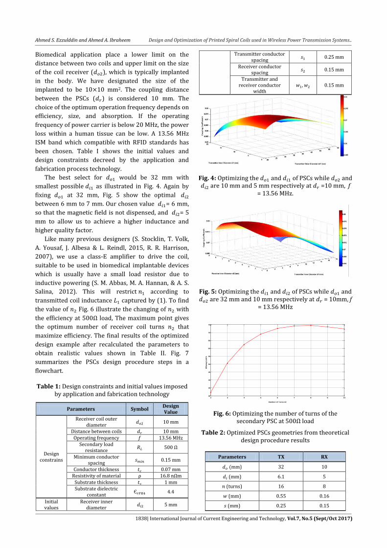
the value of Fig. 6 illustrate the changing of with
the efficiency at 500Ω load, The maximum point gives
the optimum number of receiver coil turns that
maximize efficiency. The final results of the optimized
design example after recalculated the parameters to
obtain realistic values shown in Table II. Fig. 7
summarizes the PSCs design procedure steps in a
flowchart.
Table 1: Design constraints and initial values imposed by application and fabrication technology
Parameters Symbol Design Value
Design constrains
Receiver coil outer diameter
10 mm
Distance between coils 10 mm Operating frequency 13.56 MHz
Secondary load resistance
500 Ω
Minimum conductor spacing
0.15 mm
Conductor thickness 0.07 mm Resistivity of material ρ 16.8 nΩm
Substrate thickness 1 mm Substrate dielectric
constant 4.4
Initial values
Receiver inner diameter
5 mm
Transmitter conductor spacing
0.25 mm
Receiver conductor spacing
0.15 mm
Transmitter and receiver conductor
width , 0.15 mm
Fig. 4: Optimizing the and of PSCs while and are 10 mm and 5 mm respectively at =10 mm, f
= 13.56 MHz.
Fig. 5: Optimizing the and of PSCs while and are 32 mm and 10 mm respectively at = 10mm, f
= 13.56 MHz
Fig. 6: Optimizing the number of turns of the secondary PSC at 500Ω load
Table 2: Optimized PSCs geometries from theoretical design procedure results
Parameters TX RX
mm) 32 10
(mm) 6.1 5
(turns) 16 8
(mm) 0.55 0.16
(mm) 0.25 0.15
2 3 4 5 6 7 8 9 1030
35
40
45
50
55
60
65
70
75
Number of Turns n2
Eff
cien
cy L
ink
%
Ahmed S. Ezzulddin and Ahmed A. Ibraheem Design and Optimization of Printed Spiral Coils used in Wireless Power Transmission Systems..
1839| International Journal of Current Engineering and Technology, Vol.7, No.5 (Sept/Oct 2017)
Fig. 7: Optimal PSCs design procedure
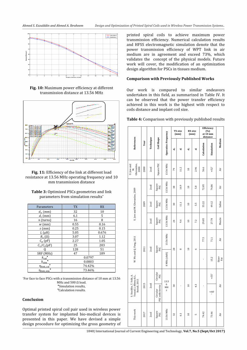
4. PSC Simulation and Results To verify the model, Fig. 8 shows the model of PSCs constructed in HFSS 14.1 on a distance in the air to find the electromagnetic efficiency. The inductance, resistance, parasitic capacitance, quality factor and coupling coefficient can be calculated from Z-parameter by using (18)-(22) (W. Wu & Q. Fang, 2011, S. Mehri, A. C. Ammari, J. Ben, H. Slama, & H. Rmili , 2016, Z. Yang, W. Liu, & E. Basham, 2007).
,
(16)
,
(17)
,
(18)
( )
(19)
√
(20)
To compute maximum power transmission efficiency, equation (15) was chosen. The simulations of the WPT
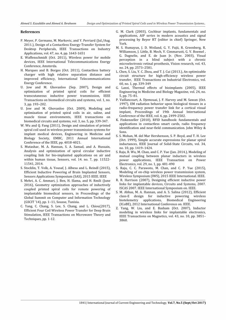
link were achieved at different transmission distances. In all these case, the inductance and resistance almost remain unchanged, but the mutual coupling was affected directly by this change. This effect was captured by (11). Maximum efficiency of WPT link at different operating frequencies shown in Fig. 9. The simulation tests were done for 10 mm transmission distance to determine the maximum efficiency of the power transmission in the entire range of operating frequencies. The result can clearly identify the power transmission efficiency value at desired operation frequency also illustrated the optimal operating frequency at which the power transmission efficiency reaches its peak value at 25 MHz. Fig. 10 compares the maximum power transmission efficiency ( ) at different relative distances whereas the operation frequency fixed at 13.56 MHz. The results show that the calculated and simulated values are in agreement. In the next step of simulation were accomplished to capture the effect of load resistance on the power transmission efficiency ( ). The load resistance was varied whereas the transmission distances and operation frequency was kept at 10 mm and at 13.56 MHz, respectively. Fig. 11 verifies that reach toward at an optimal load resistance of 500 Ω. Again the proposed model has given the simulation results in an agreeable manner. Employing this model, designers can realize the optimal operating condition and design the best efficient WPT system. The final geometries and parameters results of the applied WPT link are defined in Table III.
Fig. 8: 3D PSC model constructed in the electromagnetic field solver
HFSS 14.1 simulator
Fig. 9: Maximum power transmission efficiency at 10 mm distance for a different operating frequency
0.00 5.00 10.00 15.00 20.00 25.00 30.00 35.00 40.00 45.00
Freq [MHz]
20.00
30.00
40.00
50.00
60.00
70.00
80.00
Ma
xim
um
Effi
cie
ncy
%
Efficiency vs Frequency ANSOFT
m1
Curve Info
Efficiency
Setup1 : Sw eep
d='10mm'
Name X Y
m1 13.5600 73.5612
Ahmed S. Ezzulddin and Ahmed A. Ibraheem Design and Optimization of Printed Spiral Coils used in Wireless Power Transmission Systems..
1840| International Journal of Current Engineering and Technology, Vol.7, No.5 (Sept/Oct 2017)
Fig. 10: Maximum power efficiency at different transmission distance at 13.56 MHz
Fig. 11: Efficiency of the link at different load resistance at 13.56 MHz operating frequency and 10
mm transmission distance
Table 3: Optimized PSCs geometries and link parameters from simulation results*
Parameters TX RX
mm) 32 10 (mm) 6.1 5
(turns) 16 8
(mm) 0.55 0.16 (mm) 0.25 0.15 (µH) 5.05 0.676 (Ω) 3.07 1.12 (pF) 2.27 1.05
(pF) 25 203 Q 128 51
SRF (MHz) 47 189
♦ 0.0797
0.0803
♦ 74.42%
73.46%
*For face to face PSCs with a transmission distance of 10 mm at 13.56 MHz and 500 Ω load. Simulation results, ♦Calculation results.
Conclusion Optimal printed spiral coil pair used in wireless power transfer system for implanted bio-medical devices is presented in this paper. We have devised a simple design procedure for optimizing the gross geometry of
printed spiral coils to achieve maximum power transmission efficiency. Numerical calculation results and HFSS electromagnetic simulation denote that the power transmission efficiency of WPT link in air medium are in agreement and exceed 73%, which validates the concept of the physical models. Future work will cover, the modification of an optimization design algorithm for PSCs in tissues medium. Comparison with Previously Published Works
Our work is compared to similar endeavors undertaken in this field, as summarized in Table IV. It can be observed that the power transfer efficiency achieved in this work is the highest with respect to coils distance and implant coil size. Table 4: Comparison with previously published results
Re
fere
nce
s
Ye
ar
Te
chn
iqu
e
Co
il S
ha
pe
Op
era
tio
n F
req
ue
ncy
TX size (mm)
RX size (mm)
Efficiency (%)
at 10 mm distance
Me
diu
m
do
di
do
di
Ca
lcu
lati
on
Sim
ula
tio
n
U. J
ow
an
d
M.
Gh
ova
nlo
o,
20
08
20
08
2co
il
Squ
are
PSC
13
.56
MH
z
79
11
.2
10
2.9
6
56
.6
5
2*
Air
U. J
ow
an
d M
. Gh
ova
nlo
o, 2
00
9
20
09
2co
il
Squ
are
PSC
13
.56
MH
z
38
14
.9
10
5.8
72
.05
74
.86
Air
2co
il
Squ
are
PSC
13
.56
MH
z
30
11
.1
10
5.5
55
.22
49
.12
Sali
ne
2co
il
Squ
are
PSC
13
.56
MH
z
24
9.4
10
7.2
29
.85
27
.70
Mu
scle
W. W
u a
nd
Q. F
ang
, 20
11
20
11
2co
il
Squ
are
PSC
13
.56
MH
z
28
8
10
6
77
.5
71
.1
Air
8 M
Hz
(sh
ift)
-
15
.2
Skin
+
Fat
S. S
tock
lin
, T. V
olk
, A.
Yo
usa
f, J.
Alb
esa
& L
. R
ein
dl,
20
15
20
15
2co
il
Cir
cula
r P
SC
13.56
MHz
30
- 10
4.3
-
5
5*
Air
Cir
cula
r P
SC w
ith
fer
rite
60*
Th
is w
ork
20
17
2co
il
Squ
are
PSC
13
.56
MH
z
32
6.1
10
5
74
.42
73
.46
Air
1 3 5 7 9 11 13 15 17 19 21 23 2520
30
40
50
60
70
80
90
100
Relative Distance dr (mm)
Max
imum
Eff
icie
ncy
%
Calculation
Simulation
Ahmed S. Ezzulddin and Ahmed A. Ibraheem Design and Optimization of Printed Spiral Coils used in Wireless Power Transmission Systems..
1841| International Journal of Current Engineering and Technology, Vol.7, No.5 (Sept/Oct 2017)
References P. Meyer, P. Germano, M. Markovic, and Y. Perriard (Jul./Aug.
2011.), Design of a Contactless Energy-Transfer System for Desktop Peripherals, IEEE Transactions on Industry
Applications, vol. 47, no. 4, pp. 1643-1651 E. Waffenschmidt (Oct. 2011), Wireless power for mobile
devices, IEEE International Telecommunications Energy Conference, Amsterda.
H. Marques and B. Borges (Oct. 2011), Contactless battery charger with high relative separation distance and improved efficiency, International Telecommunications Energy Conference.
U. Jow and M. Ghovanloo (Sep. 2007), Design and optimization of printed spiral coils for efficient transcutaneous inductive power transmission, IEEE Transactions on biomedical circuits and systems, vol. 1, no. 3, pp. 193–202.
U. Jow and M. Ghovanloo (Oct. 2009), Modeling and optimization of printed spiral coils in air, saline, and muscle tissue environments, IEEE transactions on biomedical circuits and systems, vol. 3, no. 5, pp. 339-347.
W. Wu and Q. Fang (2011), Design and simulation of printed spiral coil used in wireless power transmission systems for implant medical devices, Engineering in Medicine and Biology Society, EMBC, 2011 Annual International Conference of the IEEE, pp. 4018-4021.
S. Mutashar, M. A. Hannan, S. A. Samad, and A. Hussain, Analysis and optimization of spiral circular inductive coupling link for bio-implanted applications on air and within human tissue, Sensors, vol. 14. no. 7, pp. 11522-11541, 2014.
S. Stocklin, T. Volk, A. Yousaf, J. Albesa and L. Reindl (2015), Efficient Inductive Powering of Brain Implanted Sensors, Sensors Applications Symposium (SAS), 2015 IEEE. IEEE
S. Mehri, A. C. Ammari, J. Ben, H. Slama, and H. Rmili (June 2016), Geometry optimization approaches of inductively coupled printed spiral coils for remote powering of implantable biomedical sensors, in Proceedings of the Global Summit on Computer and Information Technology
(GSCIT ’14), pp. 1–11, Sousse, Tunisia. C. Yang, C. Chang, S. Lee, S. Chang, and L. Chiou(2017),
Efficient Four Coil Wireless Power Transfer for Deep Brain Stimulation, IEEE Transactions on Microwave Theory and Techniques, pp. 1-12.
G. M. Clark (2003), Cochlear implants, fundamentals and applications, AIP series in modern acoustics and signal processing by Beyer RT (editor in chief) Springer, New York.
M. S. Humayun, J. D. Weiland, G. Y. Fujii, R. Greenberg, R. Williamson, J. Little, B. Mech, V. Cimmarusti, G. V. Boemel , G. Dagnelie, and E. de Juan Jr. (Nov. 2003), Visual perception in a blind subject with a chronic microelectronic retinal prosthesis, Vision research, vol. 43, no. 24, pp. 2573–2581.
L. Chen, S. Liu, Y. C. Zhou, and T. J. Cui (2013.), An optimizable circuit structure for high-efficiency wireless power transfer, IEEE Transactions on Industrial Electronics, vol. 60, no. 1, pp. 339-349
G. Lazzi, Thermal effects of bioimplants (2005), IEEE Engineering in Medicine and Biology Magazine, vol. 24, no. 5, pp. 75–81.
P. Vaillancourt, A. Djemouai, J. F. Harvey and M. Sawan (Oct. 1997), EM radiation behavior upon biological tissues in a radio-frequency power transfer link for a cortical visual implant, Proceedings of 19th Annual International Conference of the IEEE, vol. 6, pp. 2499-2502.
K. Finkenzeller (2010), RFID handbook: fundamentals and applications in contactless smart cards, radio frequency identification and near-field communication. John Wiley & Sons.
S. S. Mohan, M. del Mar Hershenson, S. P. Boyd, and T. H. Lee (Oct. 1999), Simple accurate expressions for planar spiral inductances, IEEE Journal of Solid-State Circuits, vol. 34, no. 10, pp. 1419–1424.
S. Raju, R. Wu, M. Chan, and C. P. Yue (Jan. 2014.), Modeling of mutual coupling between planar inductors in wireless power applications, IEEE Transaction on Power Electronics, vol. 29, no. 1, pp. 481-490
S. Raju, C. C. Parawoto, M. Chan, and C. P. Yue (2015), Modeling of on-chip wireless power transmission system, Wireless Symposium (IWS), 2015 IEEE International. IEEE.
R. R. Harrison (2007), Designing efficient inductive power links for implantable devices, Circuits and Systems, 2007. ISCAS 2007. IEEE International Symposium on. IEEE.
S. M. Abbas, M. A. Hannan, and A. S. Salina (2012), Efficient class-E design for inductive powering wireless biotelemetry applications, Biomedical Engineering (ICoBE), 2012 International Conference on. IEEE.
Z. Yang, W. Liu, and E. Basham (Oct. 2007), Inductor modeling in wireless links for implantable electronics, IEEE Transactions on Magnetics, vol. 43, no. 10, pp. 3851–3860.