Embed Size (px)
Citation preview

Design and optimization of plate heat
exchanger networks
A thesis submitted to The University of Manchester
for the degree of Doctor of Philosophy
in the Faculty of Science and Engineering
2019
Kexin Xu
Department of Chemical Engineering and Analytical Science

2
Table of contents
List of Tables ................................................................................................................ 4
List of Figures .............................................................................................................. 5
Nomenclature ............................................................................................................... 6
Abstract ...................................................................................................................... 10
Declaration ................................................................................................................. 11
Copyright Statement ................................................................................................... 12
Acknowledgement ...................................................................................................... 13
Chapter 1 Introduction ............................................................................................. 14
1.1 Introduction .......................................................................................................... 14
1.2 Objectives ............................................................................................................. 17
1.3 Thesis outline........................................................................................................ 19
Chapter 2 Literature Survey ..................................................................................... 22
2.1 Existing types of heat exchangers.......................................................................... 22
2.1.1 Shell and tube heat exchanger ....................................................................................................23
2.1.2 Plate heat exchanger ...................................................................................................................23
2.1.3 Plate-fin heat exchanger .............................................................................................................29
2.2 Factors affecting heat transfer ............................................................................... 30
2.2.1 Chevron-plate geometry .............................................................................................................30
2.2.2 Flow Arrangement......................................................................................................................32
2.2.3 Fouling .......................................................................................................................................33
2.3 Basic design method of a single PHE .................................................................... 33
2.3.1 Logarithmic mean temperature difference (LMTD) method .....................................................34
2.3.2 The 𝜺 − NTU method ................................................................................................................36
2.4 Previous literature review of plate heat exchanger design ...................................... 37
2.5 Background on network pinch............................................................................... 40
2.6 Existing methodologies for the HENs retrofit ........................................................ 44
2.6.1Pinch analysis ..............................................................................................................................44

3
2.6.2 Optimization method ..................................................................................................................46
2.6.3 Hybird Methodology ..................................................................................................................51
Chapter 3 .................................................................................................................... 53
Publication 1: Automated design of two stream multi-pass plate heat exchangers ....... 53
Chapter 4 .................................................................................................................... 63
Publication 2: Application of plate heat exchangers into heat exchanger network retrofit
without structure modification .................................................................................... 63
Chapter 5 .................................................................................................................... 65
Publication 3: A New methodology of heat exchanger network retrofit with structure
modification ............................................................................................................... 65
Chapter 6 Conclusion and Future work ..................................................................... 67
6.1 Conclusion ............................................................................................................ 67
6.1.1 Automated optimization methodology of plate heat exchangers design ....................................67
6.1.2 Application of plate heat exchanger into retrofit with fixed structure ........................................68
6.1.3 Guidelines of application of plate heat exchanger into retrofit with topology change ...............69
6.2 Future work .......................................................................................................... 69
References .................................................................................................................. 71
Total word count 37654

4
List of Tables
Table 1. Comparison of PHE and S&T (Sundén and Manglik, 2007) ................................... 25
Table 2. A selection guide of PHEs for different conditions (Sundén and Manglik, 2007) .... 28

5
List of Figures
Figure 1 Schematic diagram of a simplified preheat train, modified from Coletti and
Macchietto (2011) ...................................................................................................... 15
Figure 2 Thesis outline ............................................................................................... 21
Figure 3 Configuration of gasket plate heat exchanger (Alfalaval) ............................. 26
Figure 4 Configuration of welded plate heat exchanger (Alfalaval) ............................ 27
Figure 5 Typical plate corrugation patterns: (a) washboard, (b) zig-zag, (c) chevron, (d)
protrusions and depressions, (e) washboard with secondary corrugations, (f) oblique
washboard (Sundén and Manglik, 2007) ..................................................................... 30
Figure 6 Basic geometry of chevron plate (Shah et al., 1990) ..................................... 31
Figure 7 Three types of channels: (a) L type channel, (b) H type channel, (c) M type
channel (Arsenyeva et al., 2011) ................................................................................. 31
Figure 8 Different flow arrangement: (a) co-current flow,32, (b) counter-current flow,
(c) multi-pass flow ...................................................................................................... 32
Figure 9 An existing heat exchanger network (Asante and Zhu, 1997) ....................... 40
Figure 10 Maximum energy recovery of existing HEN .............................................. 41
Figure 11 Pinching match and network pinch ............................................................. 41
Figure 12 Trade-off after each modification ............................................................... 42
Figure 13 The details of adding new heat exchanger to overcome limited heat transfer
................................................................................................................................... 43
Figure 14 The details of stream splitting to increase heat transfer ............................... 43
Figure 15 The details of resequencing to overcome the network pinch ....................... 44

6
Nomenclature
Abbreviation
PHE plate heat exchanger
HEN heat exchanger network
GPHE gasket plate heat exchanger
WPHE welded plate heat exchanger
LMTD logarithmic mean temperature difference
NTU number of transfer units
LP linear programming
MINLP mixed integer nonlinear programming
NLP non-linear programming
MILP mixed integer linear programming
ILP integer linear programming
GA genetic algorithm
SA simulated annealing
IDE integrated different evolution
CAT Constant Approach Temperature
Re Reynold number
Nu Nusselt number
Pr Prandtl number
GAMS General Algebraic Modelling System
CFD Computational Fluid Dynamics

7
Symbols
Lp plate length
φ chevron angle
Bp plate width
dport port diameter
de equivalent diameter
Ab plate area
fch cross-section area
µ dynamic viscosity
λ heat conductivity
A heat transfer area
N total number of blocks
X number of passes for stream
h heat transfer coefficient
Q heat load
∆T logarithmic mean temperature difference
⍴ stream density
v stream velocity in each channel
t width of channel
Rf fouling resistance of streams
g flow rate of the stream
a cross-section area between channels
T temperature

8
C heat capacity
R the ratio of flow heat capacities of streams
Atotal total heat transfer area
f friction factor
∆Pheight pressure drop of height change
∆Pfriction pressure drop due to friction
H height
U heat transfer coefficient
ΔTmin minimum approach temperature
FT correlation factor
Aij matrix of incident streams on exchangers
S number of process and utility streams
E
number of heat exchanger in the existing
HEN
P column factor was added incidence matrix
TT target temperature
𝑄𝑃 cross-pinch heat transfer
HU hot utility
CU cold utility
TRC total retrofit cost
BP cost of implementing by-pass
AA cost of adding area
UC total cost of utility saving

9
Greek symbol
δ inter-plate gap
𝛽 chevron angle
Atotal total area of heat exchanger
Q0 required heat load
Subscript
b block
h hot stream
c cold stream
w wall
1 inlet
2 outlet
max maximum
exist existing

10
Abstract With the growth of energy consumption and the increase of greenhouse gas emissions, it is important to improve heat transfer efficiency and save energy. One of the most effective ways is to consider use of heat transfer enhancement for increasing heat recovery. Plate heat exchangers, which allow a small minimum temperature approach, are widely used in the energy-intensive process industries to enhance heat transfer coefficient. A major limitation of applying plate heat exchanges is the lack of reliable design methods to quantify the energy saving effectively. The key objective is to develop a novel method for a single plate heat exchanger design and integrate the plate heat exchangers into conventional heat exchanger network retrofits.
A new computer-aided design of two-stream multi-pass plate heat exchangers is proposed, including gasket plate heat exchangers and welded plate heat exchangers, with different plate geometries. To account for multi-pass flow arrangements, the plate heat exchanger is separated into several pure counter-current or co-current one-pass blocks. The correlations of inlet and outlet temperatures of different blocks are obtained in order to apply the logarithmic mean temperature difference (LMTD) method for thermal design in each single-pass block with known temperatures. The selection of the number of passes for streams, plate geometries and plate patterns are considered as integer variables to optimize the total area of plate heat exchanger. An MINLP model is developed in GAMS using ANTIGONE solver in order to derive the optimal solution. A case study is used to demonstrate the capability of proposed method to obtain the optimal solution with required heat load and constraints. The proposed design model can also be further applied to the complex heat exchanger network design.
Application of plate heat exchangers into the heat exchanger networks (HENs) retrofit increases the heat recovery due to their small minimum approach temperature. However, the installation cost of plate heat exchangers is relatively high. Thus, the optimization process is based on the trade-off between energy reduction and capital cost. For a fixed structure HEN, the heat recovery is limited. Structure modifications have the possibility of providing more energy saving but bring more cost at the same time. A decision on the best retrofit strategy to apply to a given HEN depends on the given retrofit objective. This thesis presents a methodology for the application of plate heat exchanger in HENs, both with fixed structure and with structure modification. The key point is to find the most beneficial location to apply plate heat exchangers and develop an algorithm to automatically identify the best modifications. The objective of the optimization process of HENs retrofit is to minimize the energy consumption and maximise the retrofit profit at the same time. Case studies highlight the benefits of the new approach. The results are compared with conventional technologies to provide the insight on the potential benefit of integrating plate heat exchanger into HENs retrofit. This work provides an adequate basis on which the decision can be made based on industrial applicability, profit, and energy saving.

11
Declaration
No portion of the work referred to in this thesis has been submitted in support of an
application for another degree or qualification of this or any other university of other
institution of learning.
Kexin Xu

12
Copyright Statement
i. The author of this thesis (including any appendices and/or schedules to this
thesis) owns certain copyright of related rights in it (the “Copyright”) and
s/he has given The University of Manchester certain rights to use such
Copyright, including for administrative purposes.
ii. Copies of this thesis, either in full or in extracts and whether in hard or
electronic copy, may be made only in accordance with the Copyright,
Designs and Patents Act 1988 (as amended) and regulation issued under it or,
when appropriate, in accordance with licensing agreements which the
University has from time to time. This page much form part of any such
copies made.
iii. The ownership of certain Copyright, patents, designs, trademarks and other
intellectual property (the “ Intellectual Property”) and any reproductions of
copyright works in the thesis, for example graphs and tables
(“Reproductions”), which may be described in this thesis, may not be owned
by the author and may be owned by third parties. Such Intellectual Property
and Reproductions cannot and must not be made available for use without the
prior written permission of the owner (s) of the relevant Intellectual Property
and/or Reproductions.
iv. Further information on the conditions under which disclosure, publication
and commercialisation of this thesis, the Copyright and any Intellectual
Property University IP Policy (see
http://documents.manchester.ac.uk/DocuInfo.aspx?DocID=487), in any
relevant Thesis restriction declarations deposited in the University Library,
The University Library’s regulations (see
http://www.library.manchester.ac.uk/aboutus/regulations) and in The
University’s policy on Presentation of Theses.

13
Acknowledgement
This thesis would not have been possible without the support from my family, friends
and most importantly my supervisor.
Special thanks to my supervisor Professor Robin Smith who always supports and
encourages me all through this process. Unlike me, he never lost faith in my ability to
complete this task. I am truly and forever grateful for his patient and guidance during
the project. I would like to express my appreciation to my co-supervisor Dr. Nan Zhang
for his valuable suggestions and encouragement.
Special thanks to China Scholarship Council (CSC) for the financial support, without
which all these are not possible.
I would also express my deep appreciation to my parents who stood by me and
supported me all the time. Their love always encouraged me to be better whenever I
want to give up and light up the road forward. Although my grandma did not live long
enough to see me complete this process, I am confident that wherever she is, she would
be proud that I have come this far.
To all my friends and colleagues who have contributed in different ways to the
completion of this project. Nevertheless, special thanks to Mary, Xiao, Jose, Luyi, Fei,
Nikos, Meng and the rest of CPI staff and students for their help and support whenever I
needed it. Special thanks to Steve Doyle who provided tremendous help with SPRINT
and gave me practical suggestions on the research.
Chapter 1 Introduction
14
Chapter 1 Introduction
1.1 Introduction
With the growth of energy consumption and stringent environmental protection
legislation, energy saving has been made a priority. One of the largest energy
consumers globally are the process industries. Shell-and-tube heat exchangers have
been widely used in the process industries over the past several decades (Rohsenow et
al., 1998, Manglik, 2003), but it is very difficult to reduce their relative large minimum
approach temperature and their total volume. Heat transfer enhancement technologies
are one of the most efficient and cost-effective way to enhance heat transfer behaviour,
as it usually requires low capital investment for fixed network topology, and no
additional heat transfer area in existing heat exchangers (Sheikholeslami et al., 2015).
However, for enhancement to be effective, at least 50% of the overall heat transfer
resistance must be either the tube-side film coefficient or the shell-side coefficient. If
one of the film coefficients is not controlling, applying heat transfer equipment with
high-performance heat transfer equipment, such as plate heat exchangers, is a beneficial
option to improve energy efficiency (Kakac et al., 2012, Kapustenko et al., 2009).
Plate heat exchangers are one of the most efficient heat transfer equipment (Gherasim et
al., 2011b), which use metal plates to transfer heat between fluids. Compared with
conventional shell-and-tube heat exchangers, plate heat exchangers can significantly
increase energy efficiency, enhance thermal-hydraulic performance, and reduce the fuel
consumption and CO2 emissions (Sundén and Manglik, 2007, Pantzali et al., 2009).
Plate heat exchangers have many distinct advantages (Rao et al., 2002, Gherasim et al.,
2009, Pandey and Nema, 2011, Luan et al., 2008). Among them, the most dramatic
feature is that the minimum approach temperature in plate heat exchangers can be as
low as 2°C due to high heat transfer coefficient. Besides, compared to shell-and-tube
heat exchangers, plate heat exchangers have larger surface area, lower total cost, are less
prone to fouling, and present a more flexible thermal design compared with
conventional heat exchangers (Gherasim et al., 2011a). Due to these advantages, plate
heat exchangers are widely used in various energy-intensive process industries, such as
refrigeration, petrochemical plants, refineries and natural gas processing (Hesselgreaves,

Chapter 1 Introduction
15
2001). However, no systematic methods are currently available for the design and
optimization of heat exchanger networks involving plate heat exchangers.
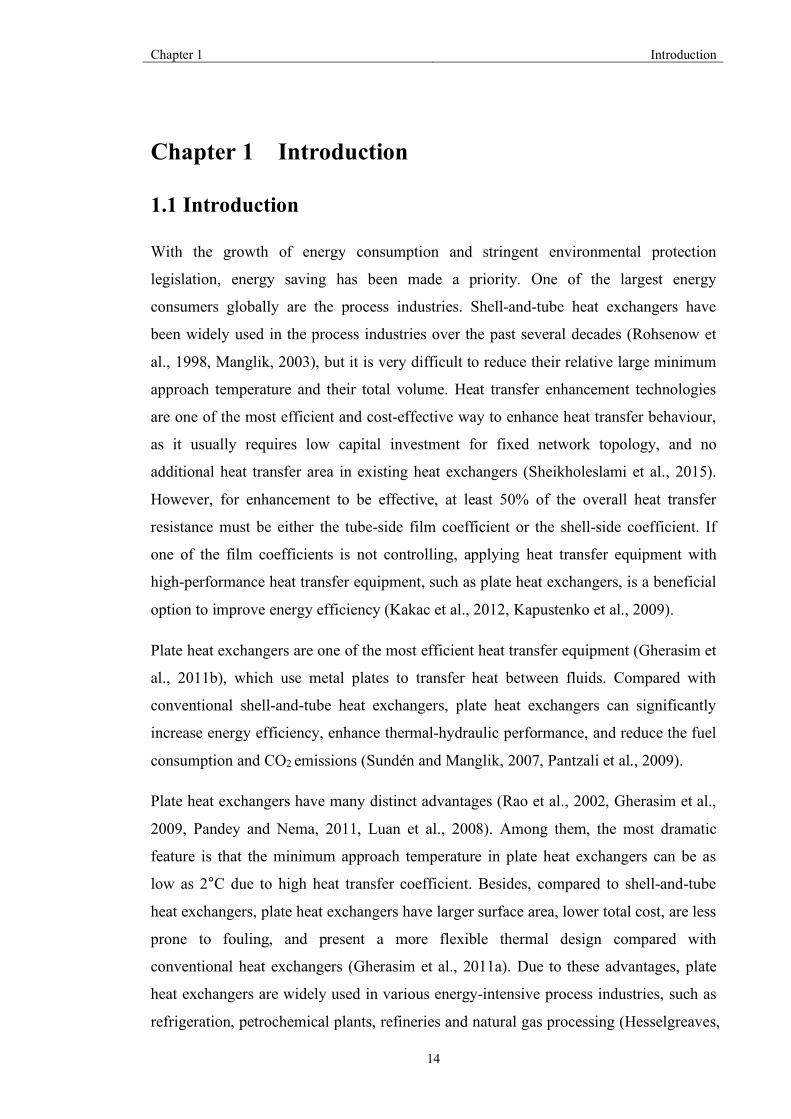
Figure 1 Schematic diagram of a simplified preheat train, modified from Coletti and Macchietto (2011)
In an oil refinery, crude oil distillation is the most energy-consuming process (Nasr and
Givi, 2006). In the distillation column, crude oil can be separated into hydrocarbon
streams according to differences in boiling temperatures. However, in order to carry out
distillation, crude oil must be heated up to 360⁰C to 380℃ before it can be fed to the
distillation column. To maximize energy savings, heat from hot side products and pump
arounds is utilised to recover heat into the crude oil. This process is called the crude oil
preheat train as shown in Figure 1, in which the heating operation is built up on a heat
exchanger network. The final heating of crude oil is carried out in a furnace (Borges et
al., 2009). By introducing preheat train, the energy demand for heating crude oil up to
the desired temperature dramatically reduces, which could provide 60%-70% of the
total energy demands (Gonçalves et al., 2014). However, during the operation of the
preheat train, the thermal efficiency of conventional heat exchanger networks decreases
due to fouling and large minimum approach temperatures. Thus, to increase energy
savings and reduce fouling possibility, plate heat exchangers are taken into
consideration to replace the conventional heat exchanger in crude oil preheat trains.
Naphtha and gases
Kerosene
Light gas oil
Heavy gas oil
Reduced crude
Crude Storage
Furnace
Desalter
Distillation columnNaphtha
Kerosene
Heavy gas oil
Light gas oil
Bottom pump around
Reduced crude

Chapter 1 Introduction
16
Plate heat exchangers, which include gasket plate heat exchangers and welded plate heat
exchangers, use metal plates to transfer heat between fluids (Shah and Focke, 1988).
Welded plate heat exchangers are gasket free. Between the two end plates, a completely
welded plate pack is bolted in a conventional frame. The special structure of welded
plate heat exchangers dramatically enhances their integrity, which makes it possible to
operate in the condition of high temperature (up to 350⁰C) and high pressure (40 bar)
(Sundén and Manglik, 2007). As for the gasket plate heat exchangers, due to the
limitation of gaskets, this type of heat exchanger could only handle fluids with less than
200⁰C, and the pressure should be no more than 25 bar (Abu-Khader, 2012) . Besides,
the high turbulence generated by chevron-plate pattern in welded plate heat exchangers
leads to high overall heat transfer coefficients, which are three to five times that of
conventional shell-and tube heat exchangers. Thus, considering of the operation
conditions and specific structures, welded plate heat exchangers are possible to apply in
crude oil preheat trains.
By applying welded plate heat exchanger into crude oil preheats trains, the greenhouse
gas emission and fuel consumption can be significant reduced. Take a refinery plant
with crude distillation capacity 40000 bbl/d as an example. If we apply two optimized
welded plate heat exchangers to this crude oil preheat train, the annual fuel savings
would be 427,000 USD, in which we assume that fuel value is 35/bbl USD. Also, the
annual emission savings would be 130,000 USD, in which we assume that CO2 value is
15/ton USD (Alfalaval, 2015). Based on the BP Statistical Review of World Energy in
June 2017, the total world refinery throughputs in 2016 are 76,833 thousand barrels
daily, which means the annual fuel savings would be 820,000 thousand USD and the
annual emission savings would be 247,000 thousand USD if we replace two
conventional shell-and-tube heat exchanger in each of the preheat trains.
However, most data are industry-owned so far and there is no published methodology to
quantify the benefits of energy saving. Researchers are now focusing on investigating
the effect of fouling issues (Ishiyama et al., 2009, Panchal and Huangfu, 2000,
Markowski et al., 2013). Welded plate heat exchangers are less prone to fouling due to
higher shear stress and turbulent flow (Abu-Khader, 2012). However, since plate heat
exchangers are still regarded as a new technology in the refineries, the potential benefits
of replacement need to be validated before they are widely used.

Chapter 1 Introduction
17
This project will develop the first truly systematic methods for design and optimization
for plate heat exchangers, and apply them for the retrofit of heat exchanger network.
This research is not restricted to the application of plate heat exchanger into crude oil
preheat trains. The approach can be used into more complex networks. The crude oil
preheat trains is only used as a case study to show the possibility to integrate plate and
shell-and-tube heat exchanger into heat exchanger networks and quantify the benefit.
1.2 Objectives
Currently the challenges of applying plate heat exchangers into heat exchanger
networks are: 1) lack of general design method of plate heat exchangers, including
welded plate heat exchangers and gasket plate heat exchangers; 2) identifying the best
heat exchangers to replace in retrofit; 3) develop the most cost effective retrofit plan.
Thus, this research project will develop systematic methods for design and optimization
of plate heat exchanger networks. The benefits of the proposed methodology, for
example energy saving and total cost, will be quantified through different case study.
This research work is focusing on tackling with three problem and the related research
objectives are listed below.
Objective 1:
Develop an algorithm for optimal design of plate heat exchangers, including welded and
gasket plate heat exchangers:
The heat transfer and pressure drop performance data of plate heat exchangers are
industrially owned, especially for welded plate heat exchangers. However, for
welded plate heat exchangers, Nusselt number and friction factor expressions can be
considered to be the same as gasket plate heat exchangers (Picón-Núñez et al., 2006).
Thus, this project aims to develop a general design methodology for plate heat
exchangers, which includes selection of plate pattern, determination of flow
arrangement and pressure drop consideration simultaneously. Therefore, the research
questions for this project based on the objectives are:
Question a: How to integrate flow arrangements into the design model and how to
model different flow arrangements?

Chapter 1 Introduction
18
Question b: How to build the design model so that it can automatically select the
most cost-effective combination of plate geometries, chevron angle and flow
arrangement depending on the given process data?
Objective 2:
Develop an optimization method of integrating a mixture of plate and shell-and-tube
heat exchangers into heat exchanger networks without the need for topology
modifications
This objective is to develop a novel methodology for the use of plate heat exchangers
in heat exchanger retrofit. Integrating plate heat exchangers into a conventional heat
exchanger network can significantly reduce energy cost and enhance heat recovery.
However, the cost of installing new plate heat exchangers is high. Thus, a reasonable
retrofit is one that has the right balance between efficient use of existing equipment
and limited amount of modifications, while maximizing energy recovery. To ensure
industrial applicability, this objective aims to propose a cost-effective retrofit design
of HEN without topology modifications. The research questions are:
Question a: How to identify the best heat exchangers in the existing HEN to replace?
What are the criteria of the number of heat exchangers to replace?
Question b: How to deal with downstream effect after applying plate heat
exchangers? How to quantify the benefit of retrofit?
Question c: How to deal with two different heat transfer technologies in one heat
exchanger network, especially when it comes with two different minimum approach
temperatures?
Objective 3:
Develop a novel methodology for applying plate heat exchangers into HENs retrofit
with structural modifications:
Through applying plate heat exchangers in retrofit design of existing HENs, the
amount of energy saving is limited without structural modifications. On one hand,
structural modifications are possible to increase heat recovery; on the other hand,
they are costly because of high expense on piping work and possibly civil
engineering. The challenge of modification is to identify the location which can bring
most retrofit profit to apply plate heat exchangers. The research questions are:

Chapter 1 Introduction
19
Question a: How to identify the location for installing plate heat exchangers?
Question b: How to quantify the potential benefit of applying plate heat exchangers
into retrofit design of heat exchanger network? Energy saving or total retrofit cost or
payback time?
Question c: Since the plate heat exchangers have smaller minimum approach
temperature and potentially more energy saving compared with shell and tube heat
exchanger, how to set up the objective of energy saving?
Question d: How to tackle with two different minimum approach temperatures
caused by different type of heat exchangers in one heat exchanger network?
1.3 Thesis outline
The “journal format”, which including the published or submitted papers, is used in the
organization of this PhD thesis to fulfil the requirement of The University of
Manchester. In total, this thesis is report is separated into 6 chapters. The outline of this
thesis and the connection between different chapters are shown in Figure 2.
Chapter 1 introduces the main motivation and challenges of develop an optimization
model for multi-pass plate heat exchangers. The potential benefit of application of plate
heat exchangers into a heat exchanger network is highlighted also. The three main
research gaps to tackle within this research work and three related objectives are
detailed.
Chapter 2 presents a review of detailed background on plate heat exchangers, and other
different types of heat exchangers, the important factors that affect the heat transfer and
different methodology on thermal-hydraulic design of plate heat exchangers are
reviewed. The literature review on the retrofit of heat exchanger network is detailed,
including three existing retrofit method and network structure analysis.
Chapter 3 illustrates a new computer-aided methodology of design and optimization of
multi-pass plate heat exchangers, which includes gasket plate heat exchangers and
welded plate heat exchangers. This chapter is the basis of Chapters 4 and 5, since this
optimized model is applied to the heat exchanger network retrofit. A MINLP model is
formulated based on the selection of best geometries and number of passes of streams to
optimize the area of plate heat exchangers.
Chapter 4 is focused on the application of plate heat exchangers into heat exchanger
network retrofit with a fixed network structure. To deal with Objective 2, this chapter

Chapter 1 Introduction
20
tackles the challenge of integration of plate heat exchanger into conventional heat
exchanger networks. A method of dealing with two different minimum approach
temperatures is presented. The most sensitive heat exchanger to be placed is identified,
and potential benefit is quantified.
Chapter 5 presents a novel step-by-step methodology of applying plate heat exchanger
into retrofit of HENs based on topology changes. A new network pinch methodology is
used to identify the best retrofit strategy and best location to apply modifications. The
objective is to achieve the energy target with minimum modification steps and
minimum total retrofit cost. A distinctive feature of the new proposed method is the
ability to consider different minimum approach temperatures for the different types of
exchangers used in the network within an optimization framework. To quantify the
potential benefit of applying PHEs into HEN retrofit with structure modifications, the
retrofit results are compared with the results allowing adding shell-and-tube heat
exchangers into HEN retrofit by following the same guidelines.
Chapter 6 presents the main findings of this research work, and the limitations and their
corresponding possible improvements are highlighted. The recommendations for future
work are discussed at the end of this Chapter.

Chapter 1 Introduction
21
Chapter 1: Introduction
Background, Motivation, Research Objectives
Chapter 2: Literature Survey
Review of previous work on plate heat exchangers design and HEN retrofit
Chapter 3: Single plate heat exchanger
Publication 1: A new computer-aided optimization-based method for the design of single multi-pass plate heat exchangers
Chapter 5: Structural Modifications
Publication 3: New guidelines for the application of structural changes in heat exchanger network
Chapter 4: Fixed structural
Publication 2: Application of plate heat exchangers into heat exchanger network retrofit without
structure modifications
Chapter 7: Conclusions and Future Work
Summary of key findings from the thesis and future work
Main Flow Uses information from
Figure 2 Thesis outline

Chapter 2 Literature Survey
22
Chapter 2 Literature Survey
Over the past several decades, there has been an increasing concern about the energy
saving and carbon emissions. One of the effective ways to reduce the energy
consumption is to increase the heat recovery in energy systems. In conventional heat
exchanger networks, shell and tube heat exchangers are commonly used. There has been
an increasing emphasis on using more effective technologies to improve heat recovery
in heat exchanger networks, which is main objective in this research. Heat transfer
enhancement is one of the main techniques due to its relatively simple piping work and
low capital cost. However, for enhancement to be effective, one of the heat transfer
coefficients must be controlling. Besides, the energy saving is limited by applying heat
transfer enhancement. Under this circumstance, heat transfer equipment with higher
energy-efficiency heat exchangers is considered. Therefore, at the beginning of this
chapter, the existing common-used types of heat exchangers and their corresponding
advantages are reviewed. Among them, the notable features of plate heat exchangers are
stressed. In addition, the factors that affect heat transfer in plate heat exchanger are
reviewed. This is followed by the previous optimization methodologies of plate heat
exchanger design. To integrate plate heat exchangers into retrofit design of heat
exchanger networks, the existing methods of HEN retrofit are reviewed. Pinch analysis,
mathematical programming, and hybrid methods which are combinations of the other
two methods, are the three main methodologies for HENs retrofit. Ideally, the best
retrofit strategy should have the fewest steps of modifications and lowest capital cost.
To achieve this goal, plate heat exchangers can be considered to be integrated into heat
exchanger networks as they have relatively high heat transfer coefficients. Keeping the
existing structure of the network in the retrofit design it is possible reduce the piping
work and economic cost. But the energy saving is limited due to the restriction of the
fixed structure. The second part of the literature survey detailed the reason caused the
redundant use of energy and reviewed various methodologies of the existing
methodologies of the retrofit of HENs.
2.1 Existing types of heat exchanger
A heat exchanger is a device that can transfer heat between two or more fluids at
different temperatures. The fluids may be in direct contact or be separated by a solid

Chapter 2 Literature Survey
23
wall to prevent mixing (Shah and Sekulic, 2003). Heat exchangers have been applied in
a variety of industries, such as chemical, food, electronics, environmental engineering,
refrigeration, and air-conditioning. There are plenty of heat exchangers, which could be
divided into several classifications according to different criteria (Hewitt et al., 1994).
However, in this part, only three types of heat exchangers most widely used are
introduced in detail: shell-and-tube heat exchangers, plate heat exchangers, and plate-fin
heat exchangers.
2.1.1 Shell and tube heat exchangers
This type of exchangers consists of round tubes, which are mounted in a cylindrical
shell with the tubes parallel to the shell. One fluid flows inside the tubes, the other one
flows over the outside of the tube so that it can transfer heat or absorb heat in this way
(Shah and Sekulic, 2003). Due to the shape of shell and tube heat exchangers, they are
robust. So typically shell and tube heat exchangers are used for high-pressure
applications, normally, the temperature allowance is higher than 260 °C and the
pressure allowance is greater than 30 bar (Saunders, 1988).
The conventional shell and tube heat exchanger is the most common used type of heat
exchanger in crude oil preheat trains (Ishiyama et al., 2010). Although the researchers
found some enhancement devices to improve its performance (Bergles, 1998), it still
has a large volume, relatively large minimum approach temperature and a fouling
tendency.
2.1.2 Plate heat exchanger
This type of heat exchanger consists of a number of metal plates, and fluids transfer heat
by flowing between the plates. Since the fluids spread out over the plate, the fluids
could be exposed to larger surface area than conventional heat exchangers. Plate heat
exchangers, including gasket plate heat exchangers and welded plate heat exchangers,
are one of the most efficient types of heat transfer equipment. The main advantages of
plate heat exchanger are as follows:
1. The heat transfer surface area is easily changed because of the flexible plate size,
flow arrangements and plate patterns in gasket designs.
2. The heat transfer coefficient is much higher than shell-and-tube heat exchanger due
to the corrugations of plates. By introducing swirl, reducing hydraulic diameter,

Chapter 2 Literature Survey
24
increasing heat transfer area, the heat transfer coefficient of plate heat exchanger is
significantly enhanced.
3. Owing to the high heat transfer coefficient, and the pure counter-flow arrangement,
the surface area is dramatically reduced. For a given duty, the total volume of plate
heat exchanger is twice or three times smaller than that of shell-and-tube heat
exchanger.
4. Due to the high shear rate, and high turbulence, the fouling tendency could be
minimized, which could be reduced by up to 10% of that of traditional shell-and-tube
heat exchanger.
5. The minimum approach temperature is dramatically reduced owing to the high heat
transfer coefficient and true counter-flow arrangement. It could be as low as 1⁰C. As
a result, 90% heat recovery could be achieved. However, only 50% heat recovery
could be obtained by shell-and-tube heat exchangers.
6. It is possible for plate heat exchangers to heat or cold down several fluids in a single
plate heat exchanger by introducing intermediate divider sections between the plates.
7. In a single plate heat exchanger, plates with different pattern could be combined.
Selection of different flow arrangement could also be considered. The flexibility
makes it possible to do a better optimization of a plate heat exchanger.

Chapter 2 Literature Survey
25
In general, the main advantages of plate heat exchanger are all listed and the
comparison of the main operation conditions of plate heat exchanger and shell-and-tube
is stated in Table 1.
However, the main limitation of plate heat exchangers is that they can only be applied to
process with relatively low pressure and temperature. This is because the material of
gasket could not bear high temperature or some corrosive fluids. In the most
applications of plate heat exchanger, the upper bound temperature is about 160⁰C,
though some gaskets with special material could withstand temperature up to 400⁰C
(Wadekar, 1998, Manglik and Muley, 1993). In order to eliminate this limitation,
several different types of plate heat exchangers have been developed. Among them,
welded plate heat exchanger (WPHE) is the main type of plate heat exchangers.
2.1.2.1 Gasket plate heat exchanger
Table 1. Comparison of PHE and S&T (Sundén and Manglik, 2007)
Plate heat exchanger S&T heat exchanger
Temperature cross Impossible Possible
Approach △T 1℃ 5℃
Multiple duty Possible Impossible
Piping connections From one direction From several directions
Heat transfer ratio 3-5 1
Operating weight ratio 1 3-10
Hold-up volume Low High
Space ratio 1 2-5
Leakage detection Easy to detect Difficult to detect
Access for inspection On each side of plate Limited
Disassembly time 15 min 60-90 min
Fouling ratio 0.1-0.25 1

Chapter 2 Literature Survey
26
In this type of heat exchanger, gaskets seal the edge of the plates and the plates are held
together in a frame, as shown in Figure 3. Normally, there is a fixed end cover with
connecting ports and a removable end cover in the frame. The upper and bottom
carrying bars are used to guarantee the alignment of the suspended plates. Long bolts
can be used to clamp together plates with a fixed end cover. In this way, the gaskets are
compressed and a seal is formed.
In each plate, there are four ports in the corner, which provide the access to the flow
passages on either of the plates. The corner ports are arrayed to form distribution
headers when the plates are assembled so that the two fluids could go through the ports.
When the two fluids go through different plates, the heat could be transferred. This type
of plate heat exchanger is relatively flexible due to its structure, and the plates could be
easily added or removed.
.
2.1.2.2 Welded plate heat exchangers
Welded plate heat exchangers are built around a pack of corrugated heat transfer plates,
welded alternately to form channels as shown in Figure 4. By eradicating the gaskets,
the integrity of heat exchanger is dramatically improved and the upper limit of
temperature and pressure is increased. However, at the same time the welded plate heat
Figure 3 Configuration of gasket plate heat exchanger (Alfalaval)
Chapter 2 Literature Survey
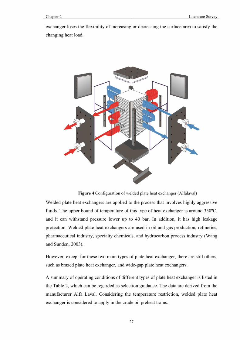
27
exchanger loses the flexibility of increasing or decreasing the surface area to satisfy the
changing heat load.
Welded plate heat exchangers are applied to the process that involves highly aggressive
fluids. The upper bound of temperature of this type of heat exchanger is around 350⁰C,
and it can withstand pressure lower up to 40 bar. In addition, it has high leakage
protection. Welded plate heat exchangers are used in oil and gas production, refineries,
pharmaceutical industry, specialty chemicals, and hydrocarbon process industry (Wang
and Sunden, 2003).
However, except for these two main types of plate heat exchanger, there are still others,
such as brazed plate heat exchanger, and wide-gap plate heat exchangers.
A summary of operating conditions of different types of plate heat exchanger is listed in
the Table 2, which can be regarded as selection guidance. The data are derived from the
manufacturer Alfa Laval. Considering the temperature restriction, welded plate heat
exchanger is considered to apply in the crude oil preheat trains.
Figure 4 Configuration of welded plate heat exchanger (Alfalaval)

Chapter 2 Literature Survey
28
Table 2. A selection guide of PHEs for different conditions (Sundén and Manglik, 2007)
Gasketed Brazed Semi-welded Fully welded Wide gap Double
wall
Operating conditions
Pressure [bar] 2.5 3 2.5 4.0 0.9 2.5
Temperature [℃] 30-200 -195-225 -30-200 -200-350 30-200 30-200
Type of service applicability
Liquid-liquid E E E E E E
Gas-liquid G-P E E-P E-P G-P G-P
Gas-gas M-P G-P G-P G-P M-P M-P
Condensation G-P E E-M E-M E-M E-M
Evaporation G-P E E-M E-M E-M E-M
Nature of type of fluid media
Corrosive/aggressive M-P M-P E E M M
Viscous E M-P E G-M E E
Heat sensitive E E E E E E
Hostile reaction M-P M G G M-P E
Fibrous P P P P E P
Slurries M-P P M M G M
Fouling G-M M M M G M
Maintenance flexibility
Mechanical cleaning B N O N B B
Repair B N O N B B
Modifications B N O N B B
Notes: E-excellent, G-good, M-moderate, P-poor, B-both sides of plate, O-one side of plate, N-no side of plate.

Chapter 2 Literature Survey
29
2.1.3 Plate-fin heat exchangers
This type of heat exchanger is a kind of compact heat exchanger that transfers heat
through fin chambers and plates. By adding fins to heat exchanger, the heat transfer
surface could be increased. Heat can be transferred to fluid through parting sheet. The
relatively small channels increase the turbulent flow of fluids. Heat transfer coefficients
are relatively higher due to the higher thermal conductivity of the fins.
There are mainly four types of fins: plain, which refer to simple straight-finned
triangular or rectangular design; herringbone, where the fins are placed sideways to
provide a zigzag path; serrated and perforated which refer to cuts and perforations in the
fins to augment flow distribution and improve heat transfer.
Compared to other types of heat exchanger, plate-fin heat exchangers have some
significant advantages as follows.
1. Heat recovery is enhanced due to the lower minimum temperature approach,
which could be as low as 1⁰C.
2. The volume of plate-fin heat exchangers can be much smaller, owing to the large
surface area.
3. It provides the possibility of transfer heat between three fluids or more, which
could reduce the number of heat exchangers.
4. It has a high degree of flexibility since it can operate with any combination of gas,
liquid, and two-phase fluids.
5. Fins increase the structural integrity of the heat exchanger and make it possible
for heat exchangers to withstand higher pressures.
Due to the compact size, lightweight characteristics and small temperature difference of
plate-fin heat exchangers, this type of heat exchanger is widely used in the aerospace
industry and cryogenics (Shah and Sekulic, 2003). However, there are some drawbacks
of plate-fin heat exchanger. First, it is more likely to suffer from fouling issue due to its
small flow channels. Second, the cost of maintenance and manufacture is high. More
importantly, the operating temperature is relatively low, which cannot satisfy the
process temperature requirements.

Chapter 2 Literature Survey
30
2.2 Factors affecting heat transfer
When optimizing a plate heat exchanger, several factors can affect heat transfer. In this
section, chevron-plate geometry and flow arrangements are introduced to state how they
influence heat transfer behaviour. In addition, the previous optimal design methods of
plate heat exchanger are reviewed.
2.2.1 Chevron-plate geometry
There are a numbers of plate type configurations, such as washboard, chevron, and
zigzag to choose when designing a plate heat exchangers, as shown in Figure 5.
However, among the 60 different types of plate pattern, the chevron-plate has proved to
be the most efficient one and is widely used in plate heat exchanger over the decades
(Kakac et al., 2012).
Figure 5 Typical plate corrugation patterns: (a) washboard, (b) zig-zag, (c) chevron, (d) protrusions and depressions, (e) washboard with secondary corrugations, (f) oblique washboard
(Sundén and Manglik, 2007)

Chapter 2 Literature Survey
31
Almost 20 types of chevron plates with different sizes and chevron angles are available.
Different plate geometries can lead to different heat transfer behaviour and pressure
drop. Thus, to optimize a single welded plate heat exchanger, chevron-plate geometry
should be considered.
The basic geometry of the chevron plate is shown in Figure 6, and it can be seen clearly
that the main parameters of the single plate are plate length for heat transfer (LP),
chevron angle (φ), plate width for heat transfer (Bp). Among them, chevron angle is an
important factor that dramatically influences heat transfer.
There are three different corrugation plates with different chevron angle as shown in
Figure 7. The H-type channel has relatively large heat transfer and pressure drop, for
which the chevron angle is about 60°. However, the chevron angle of L-type channel is
30°, which have lower intensity of heat transfer and hydraulic resistance. M-channels
combine H-type channels and L-type channels so that make it possible for this type
channel to make intermediate heat transfer.
Figure 7 Three types of channels: (a) L type channel, (b) H type channel, (c) M type channel (Arsenyeva et al., 2011)
L
LP
B BP
Figure 6 Basic geometry of chevron plate (Shah et al., 1990)

Chapter 2 Literature Survey
32
Cold stream
Hot stream
2.2.2 Flow Arrangement
In plate heat exchangers, there are three types of generalized flow arrangements to
achieve heat transfer between fluids, as shown in Figure 8 as shown: (a) co-current flow
(b) counter-current flow (c) multi-pass flow arrangement.
Hot stream
Cold stream
Cold stream
Hot stream
Figure 8 Different flow arrangement: (a) co-current flow,
(b) counter-current flow, (c) multi-pass flow

Chapter 2 Literature Survey
33
Co-current flow and counter-current flow are the two basic patterns. However, counter-
current is more widely used in industry than co-current flow owing to its relatively high
heat transfer efficiency.
Single pass is that pattern when both of cold and hot streams flow in a single direction
through all the channels. Similarly, a multi-pass arrangement is the pattern when any of
cold or hot streams flow in more than more direction. For the multi-pass arrangements,
the fluids would stay for more time and have a longer distance in welded plate heat
exchangers, which may lead to better heat transfer. The number of passes of each stream
can be different, especially when the pressure drop on one side needs to minimized or
the ratio of the flow rate is relatively high, then different numbers of passes are
considered.
However, among the numerous multi-pass arrangements, only a few arrangements are
applied in practice in industry. Consideration of pressure drop constraint,normally the
number of passes are not exceeded four.
2.2.3 Fouling
Fouling phenomena significantly decreases the thermal effectiveness to heat flow
(Webb and Kim, 1994), which is a key factor that affects the application of plate heat
exchanger into chemical processes (Abu-Khader, 2012). An insulting layer created by
deposits over the surface of plate heat exchangers dramatically narrows the flow area,
which leads to the increase of hydraulic and thermal disturbances (Sundén and Manglik,
2007). As a result, an additional cost for energy lost and cleaning expenses is added to
industrial processes. Thus, to maintain the production efficiency, deposits that causes
fouling must be removed by cleaning procedures.
2.3 Basic design method of a single PHE
The methodology employed for design of plate heat exchangers is generally the same
as the thermal-hydraulic design methods for other types of heat exchangers (Shah et al.,
1988, Raju and Bansal, 1983). There are five considerations when designing a plate heat
exchanger as follows:
1. Process specifications
2. Thermal-hydraulic design
3. Operation and maintenance constraints, mechanical design

Chapter 2 Literature Survey
34
4. Manufacturing consideration
5. Trade-off consideration and optimization
In this part, the general thermal-hydraulic design methods are stated in detail. Sizing
and rating problems are the two fundamental problems in heat exchangers design. The
rating problem is to derive the outlet temperature of fluids and the total heat load with a
given geometry of heat exchanger and inlet temperature of fluids. However, for a sizing
problem, the total heat load and both of inlet and outlet temperature of fluids are given.
The aim of this type of problem is to determine the geometry of heat exchange, total
area, and flow arrangement. (Shah, 1983, Thonon et al., 1995)
There are two main methods to perform thermal design for plate heat exchanger, which
include logarithmic mean temperature difference (LMTD) method and ℇ-number of
transfer units (NTU). Shah and Mueller (1985) summarized other methodologies.
2.3.1 Logarithmic mean temperature difference (LMTD) method
The logarithmic mean temperature difference is a logarithmic average of the
temperature difference between the hot and cold fluids at each end of the heat exchanger,
which is used to determine the temperature driving force for heat transfer in heat
exchangers. The larger the LMTD, the more heat is transferred. The LMTD is defined
by the logarithmic mean as follows:
𝐿𝑀𝑇𝐷 = /012/0345(781783
) (1)
In the above equation,Δ𝑇< represents the temperature difference between the two fluids
at inlet or outlet. Δ𝑇= is the temperature difference between the other end. LMTD is
used to calculate total transferred heat in heat exchanger:
𝑄 = 𝑈 × 𝐴 × 𝐿𝑀𝑇𝐷 (2)
Where 𝑄 is the total heat load, W; 𝑈 is the heat transfer coefficient, W/(K·m2), 𝐴 is the
surface area of heat exchanger, m2.
LMTD could be derived by the following method. Select an element of area in a heat
exchanger, the heat transfer flux could be:
𝑑𝑄 = 𝑈 × 𝑑𝐴 × ∆𝑇 = 𝑈 × 𝑑𝐴 × (𝑇C − 𝑇D) (3)

Chapter 2 Literature Survey
35
Assume that the heat transfer coefficient is constant; the above equation can be used
across the entire surface area. On the other hand, by employing the energy balance
equations, the heat transfer flux could be:
𝑑𝑄 = 𝐶C × 𝑑𝑇C = 𝐶D × 𝑑𝑇D (4)
Where 𝐶C and 𝐶D are the heat capacity of hot and cold fluids respectively,J/(kg·K).
Combining Equations (3) and (4), we can get:
𝑑(𝑇C − 𝑇D) = 𝑑𝑄( <FG− <
FH) (5)
Then we obtain:
I(0H20G)0H20G
= 𝑈( <FG− <
FH)𝑑𝐴 (6)
For co-current flow, the integrated equation for the entire heat exchanger is:
𝑇C,K − 𝑇D,K = L𝑇C,M − 𝑇D,MNexp R𝑈𝐴 S<FG+ <
FHUV (7)
Where 𝑇C,K and 𝑇D,K are the outlet temperature of the hot stream and cold stream, K;
𝑇C,Mand 𝑇D,M are the inlet temperatures of hot stream and cold streams, respectively.
Similarly, for counter-current flow, we can obtain:
𝑇C,K − 𝑇D,M = L𝑇C,M − 𝑇D,WNexp R𝑈𝐴 S<FG− <
FHUV (8)
By combining Equations (4), (7) and (8), we obtain:
𝑄 = 𝑈𝐴 (0H,X20G,Y)2(0H,Z20G,X)45(0H,X20G,Y/0H,Z20G,X)
= 𝑈𝐴 ∆012∆03
45(∆81∆83)
(9)
This equation can only be used for single-pass plate heat exchangers. As for the multi-
pass flow arrangements, it becomes more complex when it comes to the mean
temperature. A correction factor F is introduced to correct LMTD in counter-flow.
𝑄 = 𝑈 × 𝐴 × 𝐹 × ∆𝑇𝐿𝑀𝑇𝐷 (10)
Where F is the ratio between true mean temperature difference and LMTD, it is fixed by
the flow arrangement, the ratio between the heat capacity of two streams R and the heat
transfer effectiveness 𝜀.

Chapter 2 Literature Survey
36
𝐹 = 𝑓(𝑅, 𝜀, 𝑓𝑙𝑜𝑤𝑎𝑟𝑟𝑎𝑛𝑔𝑒𝑚𝑒𝑛𝑡) (11)
𝜀 = 0G,Y20G,X0H,X20G,X
(12)
𝑅 = FGFH
(13)
However, there is no specified method to calculate the correction factor for different
flow arrangements. The traditional method is to create corresponding graphs for
selected flow arrangement by analytical and numerical methods.
2.3.2 The 𝜺 − NTU method
Although LMTD method is widely used in designing welded plate heat exchangers, this
method is more suitable with conditions where the inlet and outlet temperatures of
streams are given. The NTU method is used to calculate the rate of heat transfer in heat
exchangers when there is not sufficient information to calculate LMTD. This method
not only solves the design problem but also the rating problem of welded plate heat
exchangers.
We define the ratio between actual heat transfer and the maximum transfer heat that
could be achieved in the heat exchanger as heat transfer effectiveness 𝜀 as follows:
𝜀 = jjklm
(14)
𝑄nop = 𝐶nMq(𝑇C,M − 𝑇D,M) (15)
Where 𝐶nMq is the minimum heat capacity between 𝐶D and𝐶C, J/(kg · K). Combining
Equations (14) and (15), we can obtain:
𝑄 = 𝜀𝐶nMq(𝑇C,M − 𝑇D,M) (16)
At the same time, the heat transfer effectiveness 𝜀 can also be expressed by the
following function:
𝜀 = 𝑓(𝑁𝑇𝑈, 𝑅, 𝑓𝑙𝑜𝑤𝑎𝑟𝑟𝑛𝑔𝑒𝑚𝑒𝑛𝑡) (17)
Where NTU is defined as:
𝑁𝑇𝑈 = xyFkXz
(18)

Chapter 2 Literature Survey
37
In the equation above, 𝑈 is the overall heat transfer coefficient, W/(m2·K); A is the total
transfer area, m2.
𝑅 = FkXzFklm
(19)
Where 𝐶nMq and 𝐶nop are the minimum and maximum heat capacities of two streams,
J/(kg·K).
By rewriting the Equation (8), we can obtain:
𝑇C,W − 𝑇D,M = L𝑇C,M − 𝑇D.WN𝑒𝑥𝑝RxyFkXz
SFkXzFG
+ FkXzFHUV (20)
𝑄 = 𝐶CL𝑇C,M − 𝑇C,KN = 𝐶D(𝑇D,W − 𝑇D,M) (21)
By combining Equations (16), (20) and (21), the heat transfer effectiveness 𝜀 for co-
current flow can be restated as:
𝜀 =<2~p��2S<�
�kXz�klm
Uxy/FkXz��kXz�klm
�< (22)
Which can be simplified as:
𝜀 = <2~p�[2(<��)�0x]<��
(23)
Similarly, the heat transfer effectiveness 𝜀 for counter-current flow can be written as:
𝜀 = <2���[2�0x(<2�)]<2�·���[2�0x(<2�)]
(24)
The methodology of applying 𝜺 −NTU method to multi-pass flow arrangement will be
detailed in the next chapter.
2.4 Previous literature review of plate heat exchanger design
Focke (1986) tried to find the minimal heat transfer area in 1996, which was among the
earliest attempts of seeking the appropriate plate pattern. Cooper (1983) and Shah (1988)
used logarithmic mean temperature difference (LMTD) and 𝜀 − NTU method to set up a
thermal-hydraulic model of plate heat exchangers. They took plate patterns with
different geometries and pressure drop into consideration by employing trial iterations.

Chapter 2 Literature Survey
38
These traditional methods made great progress for plate heat exchanger design, but they
are time-consuming and neglect the effect of flow arrangement.
Wang and Sunden (2003) utilized a series of different correlations to predict the
performance of plates according to the specified chevron angle and Reynolds number.
When optimizing the total cost of plate heat exchangers, the conditions that include
pressure drop and without pressure drop are considered. Similarly, researchers proposed
different methods to investigate the performance of chevron-type plates in plate heat
exchangers (Martin, 1996, Tsai et al., 2009, Muley and Manglik, 1997, Muley and
Manglik, 1999, Muley et al., 1999, Heggs et al., 1997). However, these methods could
only apply to plate heat exchangers with single pass arrangements. The multi-pass flow
arrangement still fails to be included.
Mehrabian (2009) presented a design methodology for plate heat exchangers, which
could be applied manually. Heat transfer and hydraulic resistance correlations have been
estimated. Similarly, Picon-Nunez et al. (2006) proposed a graphical representation
design method to select multi-pass flow arrangement. Picon-Nunez et al. (2010) further
developed this method by proposing parameter plots to select plate patterns (Pinto and
Gut, 2002, Gut and Pinto, 2003, Gut and Pinto, 2004, Gut et al., 2004). However, this
method is too time-consuming and fails to consider the effect of chevron angle on
pressure drop and heat transfer coefficient.
By employing existing performance data, plates can be rearranged to provide an insight
in operating of a two-stream plate heat exchanger (Wright and Heggs, 2002a, Wright
and Heggs, 2002b). Though adjusting existing plates, the plate heat exchanger can
fulfill the requirement of process conditions. New correlations between Nusselt number
and friction factor were proposed by Kanaris et al. (2009), which were developed by
using CFD software to model the flow in PHE channels. However, there are still some
practical restrictions that have not been considered.
Currently, in the practical application of plate heat exchangers, it is more likely to
combine different types of plates with several chevron angles in one heat exchanger in
order to achieve better heat transfer behavior. The earliest attempt was done by Marriot
(1977), he proposed a design method of one pass flow arrangement with different
angles of plates. Considering piping and maintenance costs, a one-pass flow
arrangement has some merits. However, multi-pass flow arrangements are more
efficient for satisfying the requirement of heat load.

Chapter 2 Literature Survey
39
With relative high velocities of streams, higher heat transfer coefficients could be
achieved in multi-pass flow arrangements. Zinger et al. (1988) and Kumar (1984)
suggested the LMTD correction factor to deal with multi-pass arrangements. Pignotti et
al. (1992) developed a methodology to analysis complex flow arrangements in two-
stream recuperators, in which the overall heat transfer coefficient and fluid properties
were taken as constant. The correlations for temperature effectiveness, and NTU for
multi-pass arrangement in plate heat exchangers, have been proposed by Kandlikar et al.
(1989), which cover the number of passes up to four.
With the rapid development of computers, researchers started to seek more time saving
tools to solve this problem. Tovazshnyansky et al. (1992) set up a series of equations of
algebraic functions to calculate the different heat transfer coefficient in each pass. Then
Arsenyeva et al. (2009) further improved this method by considering the effect of mixed
plates. Then, Arsenyeva et al. (2011) and Arsenyeva et al. (2013) set up a more
complete model for the optimal design a single plate heat exchangers. This not only
took into account different channel arrangements, but also considered various flow
arrangements. However, it failed to consider fouling issues.
Najafi et al. (2010) used a genetic algorithm to develop a multi-objective optimization
for plate heat exchangers. According to the different demands, users could select the
optimal solutions based on their requirement. Mota et al. (2014) and Qiao et al. (2013)
proposed different optimization methods for considering the effect of flow arrangement
and phase change. But these methods are time-consuming and have not addressed the
effect of fouling.
Fouling has a complicated behavior, the main factors that affect fouling in plate heat
exchangers have been reviewed (Petermeier et al., 2002, Zettler et al., 2005). How
fouling influences flow distribution with variety of plate patterns and the effect of
fouling issues on flow maldistribution between channels has been investigated (Bossan
et al., 1995).
Due to the highly turbulent flow in a plate heat exchanger, it is less prone to fouling
than a shell and tube heat exchanger. Besides, the velocity profile of a plate heat
exchanger is more uniform. Thus, low velocity zones, which are most vulnerable to
fouling, are eliminated.
Fouling in the hot end of the preheat train mainly relates to high wall temperature and
low shear stress. The shear stress is relatively high in welded plate heat exchangers due

Chapter 2 Literature Survey
40
to turbulence in the flow. However, it is difficult to quantify the potential improvements.
Thus, this project will focus on develop a systematic optimization method of integrating
a mixture of plate heat exchangers and shell-and-tube heat exchangers into heat
exchanger networks and quantify the potential benefit in terms of energy saving through
analysis case studies.
2.5 Background on network pinch
For an existing heat exchanger network, pinching the network shows all the possibilities
to reduce energy consumption by utilizing the degrees of freedom for a certain network
structure. The degree of freedom is the total number of utility paths and loops in the
existing HEN. The open path that connects hot and cold utilities through process
exchangers is called utility path and the closed path from one exchanger and return back
to the same exchanger is called a loop.
Figure 9 showed as an example of an existing heat exchanger network. The heat
recovery of this HEN is 200 MW with minimum approach temperature ΔTmin of 20°C,
and Composite Curves show that ΔTmin is 22.5 °C to achieve the same amount of heat
transfer.
Figure 9 An existing heat exchanger network (Asante and Zhu, 1997)
The only one degree of freedom in this existing heat exchanger network is the utility
path as shown in the bubble region of Figure 9a. To maintain the existing structure of
the network, the only possible solution to save energy consumption is to exploit this
utility path, which starts from the heater (H) and ends up at the cooler (C). To determine
the amount of energy saving that can be achieved, the ΔTmin is reduced to 0°C and the
heat recovery is enhanced by 20MW shown in Figure 10a. It can be clearly seen from
the Figure 10b that the targeting maximum energy recovery is still larger than the one

Chapter 2 Literature Survey
41
obtained from Figure 10a.The main reason that limits the heat recovery is because the
structure of existing HEN itself.
Figure 10 Maximum energy recovery of existing HEN
The heat exchanger match, which restricts the heat recovery, is called as the pinching
match. Figure 11a shows the pinching match in the network, and the point that cold and
hot streams touch is referred as network pinch. Generally, the network pinch
temperature is derived when the minimum approach temperature is set as 10°C or 20°C.
However, we assume ΔTmin as 0°C at this stage for the sake of illustration only.
Figure 11 Pinching match and network pinch
Topology changes are the only option to solve the limited energy saving problem
caused by the network pinch. As shown in Figure 12, there is a trade-off between heat
recovery and adding extra heat transfer area when it comes with structure modification
in the retrofit design of an existing HEN. Adding a new heat exchanger and stream
splitting, resequencing and repiping are regarded as the main ways to change topology

Chapter 2 Literature Survey
42
in terms of retrofit HEN. Among them, repiping, which refers to moving of the heat
exchanger to another location, is not considered in this research since the
implementation of repiping is impractical in many situations. For example, the pressure
rating of equipment and the material of construction might not be suitable for other
streams. The detailed background on how these methods carry this out is shown as
follows:
Figure 12 Trade-off after each modification
1. Adding new heat exchanger: the reduces heat load for the existing match and adjusts
the duty below or above the pinch by creating a loop or utility path (shown in Figure 13).
Figure 13 shows an example of adding a new heat exchanger to creat a loop to explore
greater heat recovery. If the new heat exchanger is inserted next to the pinching match,
the new match with the new heat exchanger make the pinching heat exchanger to no
longer exist. Then more heat load can be removed to the pinching match and more
energy recovery is achieved through exploting the utility path. Adding the new heat
exchanger to create a utility path is only considered when there is a potentioal that the
utility exchanger to be able to increase heat load and no violation of constraints for the
network.

Chapter 2 Literature Survey
43
Figure 13 The details of adding new heat exchanger to overcome limited heat transfer
Figure 14 The details of stream splitting to increase heat transfer
2. Splitting: when the number of pinching matches in the exsting HENs are more than
one, especially when the pinching matches are located next to each other, as shown in
Figure 14, stream splitting is considered as an efficient way to achieve energy saving. If
there is more than one stream with adjacent pinched exchangers, the one with the
highest duty is selected. The selected pinched exchangers should be located on a
viarable utility path or loop in order to create an avenue to increase heat transfer and the
splitting ratio of the split stream needs to be further optimized.

Chapter 2 Literature Survey
44
Figure 15 The details of resequencing to overcome the network pinch
3. Resequencing: this refers to relocating of the exchanger in the existing HEN, which
eases the heat transfer of the pinching match through transfering heat from below to
above the network pinch. By introducing a resequence, the pinching match can increase
heat load, thus to further increase the energy saving. As shown in Figure 15, the
constraints eased by changing the sequence of the pinching match so that the pinched
exchanger is able to take up extra heat transfer with the utilization of utility path.
2.6 Existing methodologies for the HENs retrofit
This part reviews background of network pinch and different methodologies of HEN
retrofit, including pinch analysis, mathematical programming, and hybrid methods.
2.6.1Pinch analysis
Pinch analysis aims to minimize the energy consumption in the heat exchanger
networks. This is achieved in pinch analysis by reducing cross-pinch heat transfer.
Through the calculation of the thermodynamic behavior of the network, the composite
curves, grand composite curve and grid diagrams are obtained to provide an insight into
the pinch point and potential energy target. The pinch point is defined as the closet point
between the hot and cold composite curves with pinch temperatures for hot stream and
cold stream respectively. There are two basic principles for pinch analysis method to
achieve the maximum heat recovery, which have been stated by Shenoy (1995) and
Gundersen (2013). No cross-pinch heat transfer is allowed and cold or hot utilities are
not allowed to locate above or below the pinch respectively. Targeting and design stages

Chapter 2 Literature Survey
45
are the two main stages of pinch analysis. The maximum heat recovery and minimum
energy consumption are identified at the targeting stage, and the strategies and step-by-
step procedures to achieving the target energy saving based on the principles of pinch
analysis is specified at the design stage.
In 1986, the concept of pinch analysis was first introduced to the retrofit design of heat
exchanger networks by Linnhoff and Tjoe (1986). The pinch design method was used to
eliminate the cross-pinch heat transfer by rearranging heat exchangers transferring heat
across the pinch and adding new area to the heat exchangers. However, this
methodology is based on user interaction, and it relies heavily on users experience. Thus,
this methodology is not suitable for complex heat exchanger networks. A linear model
(Shokoya, 1992), which used an area matrix to reflect the detailed area distribution in
the heat exchanger network, is set up to achieve the energy target. Vertical heat transfer
between hot and cold sides is assumed at the first stage. A deviation area matrix is
defined as the target area minus the existing area matrices at the second stage. So far,
the retrofit target focused on the area, but a realistic retrofit should link the
modifications with their economic cost.
A cost-based retrofit design of HENs was proposed in 1993 (Carlsson et al.), which
involved the cost of maintenance, heat exchanger area, and piping. Criss-cross heat
transfer is allowed in this methodology. A computer-aided optimization model is
formulated to find the optimal matches with target heat recovery at certain minimum
approach temperature. The proposed methodology is not suitable for large-scale
applications since a large amount of work and computation time is required to obtain
the optimal solution.
Due to the large scale and complexity of heat exchanger networks, researchers started to
seek a methodology to simplify the HEN before solving. Path analysis, which was
proposed by Reisen et al. (1995), was used to decompose the existing heat exchanger
network and evaluate the subnetwork. By applying path analysis, the entire network is
decomposed to the subnetworks, which significantly reduces the complexities of the
problem (Sreepathi and Rangaiah, 2014). In 1998, Reisen et al.(1998) improved the
existing method by introducing zones for finding the most sensitive part in the HEN to
retrofit. The novel method specified the targeting locations to apply topology change
and could achieve more energy saving.

Chapter 2 Literature Survey
46
A graphical methodology proposed by Nordman and Berntsson (2001) was introduced
for the retrofit design of HENs. A novel pinch curve, which stressed the cross-pinch
heat transfer and the trade-off between heat transfer area and energy target, was
developed to obtain a cost-effective retrofit design. This work was further studied by
Nordman and Berntsson (2009) to investigate different scenarios of the all the possible
retrofit solutions based on economic considerations. The result of all the possible
solutions was that when replacing the heaters/ coolers closer to the pinch, a higher
economic benefit was achieved.
Li and Chang (2010) proposed a general guideline based on the pinch retrofit method.
This method was used to identify the heat exchangers that limit the heat recovery and
eliminate each cross-pinch match. The modified pinch method achieved the energy
target by dividing the heat loads into two parts and matching the new streams on the
same side of pinch point. Although checking the feasibility of the new match secures
the retrofit design is reasonable, the retrofit solutions might cause uneconomic issue.
2.6.2 Optimization methods
Optimization methods use mathematical programming models to solve the retrofit
problem based on different objectives. The key point of applying optimization method
into the HEN retrofit problem is to find an accurate method to represent the problem
and determine the optimal solution. The optimization method exploits either a
deterministic approach or stochastic approach. Deterministic approaches are normally
achieved by Non-linear programming (NLP), mixed integer linear programming (MILP)
or mixed integer non-linear programming (MINLP). The stochastic approach is based
on genetic algorithms (GA) or simulated annealing (SA).
2.6.2.1 Deterministic approach
Optimization methods were first applied to heat exchanger retrofit by Yee and
Grossmann (1986) to set up a MILP model. This MILP model was used to predict the
minimum topology change in an existing HEN by maximizing the using of heat transfer
equipment and re-matching the existing heat exchangers units. Since this methodology
is based on the existing structure of heat exchanger network, the structure of the retrofit
network is similar as the original HEN.
A novel two-stage methodology developed by Ciric and Floudas (1989) aimed to
minimize the retrofit cost of the existing HENs to achieve a certain amount of heat

Chapter 2 Literature Survey
47
recovery. An MILP model was formulated in the first stage depending on the given data
of HENs. The retrofit process allows for repiping, adding new heat exchangers, adding
extra heat transfer area and relocating the existing heat exchangers. The second stage is
to generate superstructures that show all the possible HEN structures by analysing the
results from the first stage. The MILP model is simplified to an NLP model. This work
was further extended by Ciric and Floudas (1990). The main achievement in the new
proposed method was that it combined the two-stage approach to one stage to achieve
simultaneously optimization.
A two stage retrofit methodology for HENs, which contains pre-screening and
optimization stages, was proposed by Yee and Grossmann (1991). At the pre-screening
stage, the optimal economic cost at different levels of heat recovery was to be
determined. The economic cost included utility cost, cost of adding additional heat
transfer area, and cost of topology change. The utility cost was estimated from the
model developed by Papoulias and Grossmann (1983). The additional heat transfer area
was determined by the method proposed by Townsend and Linnhoff (1984). The model
proposed by Yee and Grossman (1991) for topology change was used for calculating the
economic cost of topology change. The optimization stage optimizes the minimum
number of new heat transfer equipment requirements to obtain the optimal cost. An
MINLP model is built to select the optimal solution from all the possible superstructure
retrofit designs.
In 1999, a novel methodology, which involves screening and optimization stage for the
retrofit design of HENs, was proposed (Briones and Kokossis). At the first stage, the
integer variables were introduced to identify structure modifications and the area of heat
exchanger and heat transfer requirement were set as continuous variables. The decisions
on how many new heat exchangers and how many structure modifications were required
based on objective of the model (e.g. minimum economic cost, minimum total area).
The optimization stage uses the results from the screening stage to set up a hyper-target
and obtain the retrofit solution. The hyper-target approach used solution streams instead
of employing energy-area curves. Compared to the former methodology, this approach
effectively reduced the heat transfer area and the retrofit expense and the relevant
results are shown in the literature (Saboo et al., 1986, Ahmad and Patela, 1987, Carlsson
et al., 1993, Ciric and Floudas, 1989).
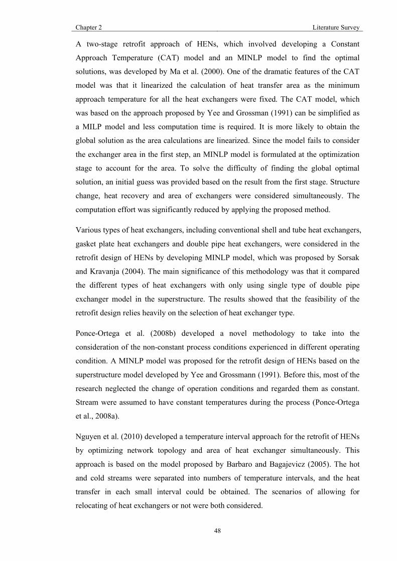
Chapter 2 Literature Survey
48
A two-stage retrofit approach of HENs, which involved developing a Constant
Approach Temperature (CAT) model and an MINLP model to find the optimal
solutions, was developed by Ma et al. (2000). One of the dramatic features of the CAT
model was that it linearized the calculation of heat transfer area as the minimum
approach temperature for all the heat exchangers were fixed. The CAT model, which
was based on the approach proposed by Yee and Grossman (1991) can be simplified as
a MILP model and less computation time is required. It is more likely to obtain the
global solution as the area calculations are linearized. Since the model fails to consider
the exchanger area in the first step, an MINLP model is formulated at the optimization
stage to account for the area. To solve the difficulty of finding the global optimal
solution, an initial guess was provided based on the result from the first stage. Structure
change, heat recovery and area of exchangers were considered simultaneously. The
computation effort was significantly reduced by applying the proposed method.
Various types of heat exchangers, including conventional shell and tube heat exchangers,
gasket plate heat exchangers and double pipe heat exchangers, were considered in the
retrofit design of HENs by developing MINLP model, which was proposed by Sorsak
and Kravanja (2004). The main significance of this methodology was that it compared
the different types of heat exchangers with only using single type of double pipe
exchanger model in the superstructure. The results showed that the feasibility of the
retrofit design relies heavily on the selection of heat exchanger type.
Ponce-Ortega et al. (2008b) developed a novel methodology to take into the
consideration of the non-constant process conditions experienced in different operating
condition. A MINLP model was proposed for the retrofit design of HENs based on the
superstructure model developed by Yee and Grossmann (1991). Before this, most of the
research neglected the change of operation conditions and regarded them as constant.
Stream were assumed to have constant temperatures during the process (Ponce-Ortega
et al., 2008a).
Nguyen et al. (2010) developed a temperature interval approach for the retrofit of HENs
by optimizing network topology and area of heat exchanger simultaneously. This
approach is based on the model proposed by Barbaro and Bagajevicz (2005). The hot
and cold streams were separated into numbers of temperature intervals, and the heat
transfer in each small interval could be obtained. The scenarios of allowing for
relocating of heat exchangers or not were both considered.

Chapter 2 Literature Survey
49
A MILP iteration model proposed by Pan et al. (2013) was developed for the retrofit
design of HENs. They applied a pinching match to the retrofit of the network
superstructure by two optimization stages. The matches with small heat duty or area
were eliminated after the optimization process in the first stage. In the second stage, the
best topology derived from the first stage was further optimized to obtain the minimal
economic cost of retrofit. Through simplification of the MINLP problem to MILP, the
proposed method significantly reduced the computation effort.
The significant advantage of deterministic optimization was that it became possible to
apply it to different types of retrofit problem with flexibility to the various scenarios.
However, due to the complexity of the non-linear model, it is relative difficult to obtain
the global optimal and solutions are sensitive to the initial points.
2.6.2.2 Stochastic-based approach
Stochastic-based approaches involve simulate annealing (SA), integrated different
evolution (IDE) and genetic algorithms (GA). Simulated annealing was applied to
retrofit design of HENs in 1996 (Nielsen et al.). The model was based on the approach
proposed by Dolan et al.(1989). The optimization process including selecting the heat
exchanger type, and thermal behaviour based on the constraints. Hydraulic resistance
was considered in the research investigated by Nielson et al.(1996).
A novel automatic two-loop methodology, using SA for the optimization of the network,
was developed by Athier et al. (1998). In the outer loop, the topology change of HEN
was optimized by SA, subject to process constraints. The economic cost of adding new
heat exchangers, repiping and relocating of heat exchangers were included. In the inner
loop, a NLP model was formulated to optimize adding extra area of heat exchanger.
Rodriguez. (2005) proposed a method for the retrofit of HENs by using SA to formulate
an optimization model, which involved integer and continuous variables. The structure
modifications were defined as integer variables and heat transfer duty and area were
defined as continuous variables. The results were not accurate as the model was
simplified.
A two-level approach making use of the GA algorithm was presented by Bochenek and
Jezowski (2006) for the retrofit design of HENs. A structure matrix was formulated
which contained multiple variables to present the key features of the network at the first
level. In the first stage, the optimization process was achieved by a GA algorithm. The

Chapter 2 Literature Survey
50
location of the splitters and heat exchanger details were obtained. These results were
used to determine the heat transfer area of exchanger and the split ratio of the splitters at
the second level. However, the complexity of the model required prolonged
optimization effort, regardless of the size of the heat exchanger network.
Razaei and Shafiei (2009) proposed an approach to integrate GA into nonlinear
programming and integer linear programming (ILP) into the retrofit design of HENs to
overcome the difficulty of handling with continuous variables in GA. The objective
function of this method was to minimize the retrofit expense and the continuous
variables were heat transfer duty, split ratio of the splitters and hot and cold stream
temperatures. These variables were optimized by the NLP model. Topology change was
determined by building a GA model to obtain the node representation of the heat
exchanger locations. At the end, the objective function was solved by an MILP model.
Zhang and Rangaiah (2013) combined the IDE model proposed by Zhang and Rangaiah
(2011), and topology representation developed by Jezowski et al. (2007) together with
model presented in 2010 (Bochenek and Jeżowski) for the retrofit design of HENs. This
method allowed it possible to deal with the different types of variables simultaneously.
A hybrid GA algorithm was developed by Liu et al. (2014) for the HEN retrofit. A
MINLP model was formulated to minimize the total retrofit cost, including the utility
cost and modification cost. The optimization procedure was divided into six steps based
on the superstructure, fully using of the existing network structure. The analysis of the
exiting HENs to select the correct retrofit sequence was produced at the first stage.
After determining the sequence of exchangers at the second stage, the locations of the
existing exchangers were represented at the third stage. Through analysing the heat
transfer area based on the hybrid genetic approach, the existing heat exchangers were
relocated in the fourth stage. The final network structure was obtained through revising
and conducting a genetic algorithm approach for the last two stages.
Compared to deterministic method, stochastic optimization method shows more
possibility to avoid local optimal solutions, but it requires more computation effort
because of the nature of the optimization process.
The main advantage of mathematical programming is that it is flexible to the retrofit
target and process data as it converts the optimization problem to the automated
mathematical model. However, it is difficult to apply mathematical programming
methods to large scale retrofit problems since it is challenging to formulate the

Chapter 2 Literature Survey
51
mathematical model accurately. The optimization process normally is achieved by one
step or multi-step. To obtain the optimal solution of retrofit problem, one step
optimization is preferred. For the multi-step optimization model, although the
computation time is possible to reduce, the effect on accuracy of results cannot be
ignored.
2.6.3 Hybird Methodology
Hybird approaches combine mathematical programming methods and pinch analysis
methods while keeping their advantages. Hybird methods can automatically obtain the
optimal solution and keep user interaction, thus it is possible to achieve the effective
retrofit solution with less computation time.
Briones and Kokossis (1996) applied a hybrid methodology into the retrofit design of
HENs, which included three stages in total. In the targeting stage, a MILP model was
formulated to find the possible solutions within the required targets of area and
modifications. The results obtained from the first stage were used in the second stage to
find the optimal solution for the exchanger area and topology changes based on the
pinch analysis method. In the third stage, a NLP model was formulated and a
superstructure derived based on the retrofit result to minimize the capital cost. However,
it is not the best retrofit solution if only energy saving is taken into consideration.
Asante and Zhu (1996) (1997) developed a methodology to minimize the steps of
topology changes to achieve the target heat transfer in the retrofit design of HENs by
applying a hybrid method. The locations that limit heat recovery and the structure
change were identified by the network pinch in the diagnosis stage. The objective of the
optimization stage was to maximize the heat recovery through rebalancing heat load
among heat exchangers after each modification. The optimal solution can be selected
with minimum retrofit cost.
Varbanov and Klemes (2000) combined pinch analysis and mathematical programming
into the retrofit design of HENs to derive various solutions of structure modification for
the existing HENs. Smith et al. (2010) further modified the network pinch approach and
combined topology changes energy-capital trade-off optimization to a single step. This
method considers the temperature dependency of the thermal properties since this gives
a true representation of the interaction in the network during retrofit.

Chapter 2 Literature Survey
52
Bakhtiari and Bedard (2013) developed a method considering of some practical
situations (e.g. stream splitting and segmentation) based on the approach proposed by
Asante and Zhu (1997). In the topology change stage, the target was to achieve the
maximum heat recovery. In the cost optimization stage, the objective was to minimize
using extra heat transfer area. The cost-energy target was possible with this
methodology.
Hybrid methods can deal with large-scale retrofit problems. This is because the method
is sequential. The utility consumption can significantly reduce due to using of degrees
of freedom of the network. However, extra area is added into the existing heat
exchanger to keep the balance of the network. The key drawback of hybrid method is
that instead of taking economic cost into the first consideration, heat recovery is always
put into the first place for the retrofit target, which may leads to high retrofit cost.

Chapter 3 Publication 1
53
Chapter 3
Publication 1: Automated design of two stream multi-pass
plate heat exchangers
(Xu, K., Zhang, N., Smith, R., Automated design of two stream multi-pass plate heat
exchangers. Chemical Engineering Research and Design, submitted)

Chapter 3 Publication 1
1
Automated design of two stream multi-pass plate heat
exchangers
Kexin Xu*, Nan Zhang, Robin Smith
Centre for Process Integration, Faculty of Chemical Engineering and Analytical
Science, The University of Manchester, M13 9PL, UK.
*Corresponding authors’ email address: [email protected]
Abstract
Gasket and welded plate heat exchangers (PHEs) have a significant potential to improve
energy efficiency in the process industries. However, to realise the full potential to
achieve such energy savings requires a systematic approach to screen the many options
available, which is currently lacking a reliable optimization approach for PHEs with
different types of flow arrangement and plate geometries. This work presents a novel
approach for the optimal design of two-stream multi-pass plate heat exchangers,
including gasket and welded plate heat exchangers, with different plate geometries and
flow configurations. This paper presents a new method to obtain the optimal global
solution with minimum total transfer area. An MINLP mathematical model is developed
to select the best combination of the flow pass configuration using available commercial
plate geometries constrained to be within practical design considerations. Two case
studies are used to demonstrate the proposed method for both gasket and welded PHEs.
Results show that better design with reduced heat transfer area by 10.71% is obtained
compared with previously proposed approaches.
Keywords: Plate heat exchanger, Optimization, design, MINLP mathematical model
Highlights:
• A design and optimization methodology for two different types of plate heat
exchangers (PHEs), including gasket and welded plate heat exchangers, is
proposed
• Plate pattern and flow arrangement selection are addressed
• Flow arrangement is integrated into the design by applying LMTD method

Chapter 3 Publication 1
2
• The total heat transfer area can be considerably decreased through the proposed
method
1. Introduction
Increasing energy consumption and CO2 emissions have created an urgent necessity to
improve energy efficiency in the process industries [1-3]. Effective exploitation of high-
performance heat transfer equipment can make a major contribution to this goal [4].
Conventional shell-and-tube heat exchangers are the most commonly used type of heat
transfer equipment [5, 6]. Although the methodologies for the design of a shell-and-tube
heat exchanger are relatively mature, their inherent design features mean that they are
largely restricted for use with relatively large temperature differences, restricting heat
recovery potential. They also have a high capital cost and large physical size, restricting
opportunities for retrofit of existing systems [6]. Additionally, shell-and-tube heat
exchangers can be readily affected by fouling deposition, especially in high-temperature
applications, such as crude oil pre-heating [7, 8]. By contrast, plate heat exchangers
(PHEs) can significantly increase heat recovery through exploitation of small
temperature differences, improve thermal-hydraulic behavior, and reduce energy
consumption and greenhouse emissions [6, 9].
There are many forms of corrugated plate and channel arrangements for PHEs [10].
Fluids stay longer in PHEs when compared with shell-and-tube heat exchangers, since
hot and cold streams flow over the entire plates [11]. For a given duty, the total volume
and weight of PHEs are three times smaller than those of shell-and-tube heat
exchangers [2]. High heat transfer coefficient in plate heat exchangers and their more
efficient flow arrangements allow minimum approach temperatures in PHEs to be as
low as 2 °C [6]. Higher heat recovery efficiency, smaller footprint, easier to deal with
fouling mitigation and lower capital cost are the main advantages over shell-and-tube
heat exchangers [6, 12]. Gasket plate heat exchangers (GPHEs) and welded plate heat
exchangers (WPHEs) are the two main types of PHEs [6]. They have different
structures as shown in Figure 1 and Figure 2. For GPHEs, the number of plates can be
adjusted by adding or removing plates, which gives a flexible thermal design to meet
the process requirement [6]. However, the gaskets restrict the temperature and pressure
to be below 200°C and 25 bar [4]. Compared with GPHEs, the integrity of WPHEs is
significantly enhanced, since plates are welded together. Consequently, WPHEs can
tolerate higher temperatures (up to 350°C) and higher pressures (up to 40 bar),

Chapter 3 Publication 1
3
exceeding the gasket limitations [4]. Owing to the unique structure of WPHEs, they are
less likely to suffer from leakage issues and are more suitable for conditions of rapid-
change [13]. Based on these distinct features, PHEs are commonly applied in food,
petrochemical plants and other energy-intensive process industries [14]. To increase
their potential to the full, it is important to enhance the thermal-hydraulic behaviour of
PHEs to reduce the capital cost further and further increase energy recovery.
Fig. 1. The structure of a gasket plate heat exchanger [1]
Fig. 2. The structure of welded plate heat exchanger (Compabloc) [1]
The heat transfer behaviour of PHEs is significantly affected by plate geometry, plate
type and flow arrangement, which needs to be systematically optimized. Figure 3 shows
the detailed corrugations of several commonly used plates. In the recent years, it has
been demonstrated that chevron-plates are the most energy-efficient plate type amongst
the over 60 different types of plates, and commonly used by manufacturers of PHEs [15,
16]. Researchers have conducted numerous experimental and numerical studies [17-23]
on how the chevron angle affects heat transfer behavior. Different chevron angles have
different Reynolds numbers and friction factors. However, in the process industries only
a small number of fixed chevron angle have been applied, as shown in Figure 4. In this

Chapter 3 Publication 1
4
work, the three most commonly-used channels are used. The H type channel, where the
chevron angle of which is 60°, has the best heat transfer behavior and the largest
resistance to flow because of high turbulence intensities and large velocities [21]. The L
type channel has a chevron angle of 30°. The small chevron angle leads to lower heat
transfer coefficient and pressure drop. M type channels, where the hydraulic resistance
and heat transfer performance are between the other two, combines the L and H type
channels. Thus, the optimization process should account for the trade-off between heat
transfer coefficient and hydraulic resistance.
The flow arrangement with the best heat transfer behavior needs to be selected
depending on the required design criteria. Although piping and maintenance expenses
are relatively low for a single-pass flow arrangement, higher heat transfer coefficients
are achieved in multi-pass flow arrangements, since fluids stay for a longer time [24].
One of the most dramatic advantages of PHEs is their flexibility to satisfy the required
process conditions by choosing different plate types, plate geometries and flow
arrangement [25]. However, these numerous choices increase the design complexity and
the difficulty of searching for the optimal design arrangement. Determination of flow
arrangement (pass arrangement for cold and hot streams), plate type and geometry
selection, and design constraint considerations (for example pressure drop) are the three
key points for the optimum design of PHEs. Most design optimization methods of PHEs
are industrially owned, and few are in the open literature.
To develop the thermal design of PHEs, the logarithmic mean temperature difference
(LMTD) and ϵ-NTU methodologies are the most commonly used approaches [6].
Cooper [26] and Shah [27] used a trial and error method to test different geometries and
find the best design solution by employing ϵ-NTU and LMTD approaches. However,
Fig. 4. Commonly-used chevron angles: (a) H type channel, (b) M type channel, (c) L type channel [3]
Fig. 3. Detailed corrugations of several commonly used plates (a) washboard (b) zigzag (c) chevron (d) Protrusions and depressions (e) washboard with secondary corrugations (f) oblique washboard [2]

Chapter 3 Publication 1
5
these methodologies take a large amount of time and do not include flow arrangement
selection. Wang and Sunder [28] presented an optimization design method for PHEs,
which adjusted all the possible plate patterns on the plate surface to maximize the
pressure drop utilization. Again, the optimization process failed to consider different
flow arrangements might obtain a better result for the design with certain constraints. A
screening method was proposed by Gut and Pinto [29]. The objective of this method
was to screen out inferior results to overcome the limitations of the mixed nonlinear
programming (MINLP) problem that was formulated. The objective of this approach
was to minimize the total area with consideration of number of passes, feed location,
and total number of plates as variables. But plate pattern selection was not considered.
Najafi and Najafi [30] developed an optimization design method of PHEs with multiple
objectives by minimizing hydraulic resistance and maximizing total area of PHE
simultaneously. This presented challenges to obtain a globally optimal design solution
and needs a considerable computation time. Picon-Nunez [31] applied an optimal plate
heat exchanger model to heat recovery. The ϵ-NTU method was employed to select
flow arrangements and evaluate the temperature correction factor. Most of the design
methods for a single PHE fail to consider all the factors that affect heat transfer
behavior.
Multi-pass arrangements enhance the heat transfer performance because of relatively
high flow velocities in channels. But, unsymmetrical passes of hot and cold streams
may diminish effective temperature differences. Initially, most of the studies [32-34]
used the LMTD correction factor to solve this problem. A closed-form formula for two-
fluid heat recovery was proposed by Pignotti and Shah [35] for the analysis of complex
flow arrangements. This method was further improved by Pignotti and Tamborenea [36]
by introducing the computer-aided method for calculating the thermal effectiveness of
arbitrary flow arrangements by employing a matrix algorithm. The formulas for up to
four passes for different flow arrangements relating to the thermal design of PHEs were
proposed by Kandlikar and Shah [37]. The details of traditional thermal design
methods, including these formulas, are available in plate heat exchanger design
handbooks [5].
With the development of computation technologies, Tovazshnyansky et al. [38]
proposed a computational method to address different heat transfer arrangements based
on blocks of of algebraic equations. Arsenyeva et al. [39] further improved this
approach. However, for practical application, the geometry of plates cannot be an

Chapter 3 Publication 1
6
arbitrary value and plates should be selected from available commercial plates, as
assumed. A method of design a multi-pass PHE was proposed by Arsenyeva et al. [3],
which includes the selection of plate type by using the ϵ-NTU method in the thermal
design. The plate geometry data collected from manufacturers can be used to build a
mathematical model to evaluate heat transfer behavior. However, this method requires a
large amount of computation time and is better to be applied as a rating problem.
Traditionally, since the entering flow rates, stream temperature data are given in a sizing
problem, the LMTD method is possibly a better option compared to the ϵ-NTU method
to simplify the design process [40]. The ϵ-NTU method might be a favorable option to
solve the rating problem, where details of geometries and the size of heat exchangers
are fully specified [2, 5, 6].
To decrease computation effort, the LMTD approach is applied in the thermal-hydraulic
design process, which integrated multi-pass flow arrangement, flow geometry, plate
type and chevron angle into automated optimization work. Currently, most of the design
methods for PHEs are focused on GPHEs, and only a very few design approaches of
WPHE available. This is because the thermal design of WPHEs is more complex than
that of GPHEs [41]. To overcome the shortcomings of previous work, this paper
presents a systematic automated methodology for the design and optimization of multi-
pass plate heat exchangers, including both GPHEs and WPHEs. The objective is to
automatically derive the optimal solution (assumed to be minimum heat transfer area)
from various flow arrangements and available sets of commercial plates within the
required duty and pressure drop allowance. Two case studies are presented to apply the
new design approach for GPHEs and WPHEs.
2. Methodology
The objective of this methodology is to optimize a plate heat exchanger by identifying a
global solution from different types of flow arrangement, various plate types, and
chevron angle for a specified process requirement. The main assumption is that there is
no maldistribution between channels and no phase transition. Another important
assumption is that fluid properties are constant.
2.1 Detailed design methodology of PHEs
The step by step methodology of PHEs design is detailed as follows, including how to
select the number of passes for the hot and cold streams, plate geometries, and develop
the model for thermal-hydraulic performance.
2.1.1 Flow arrangement selection
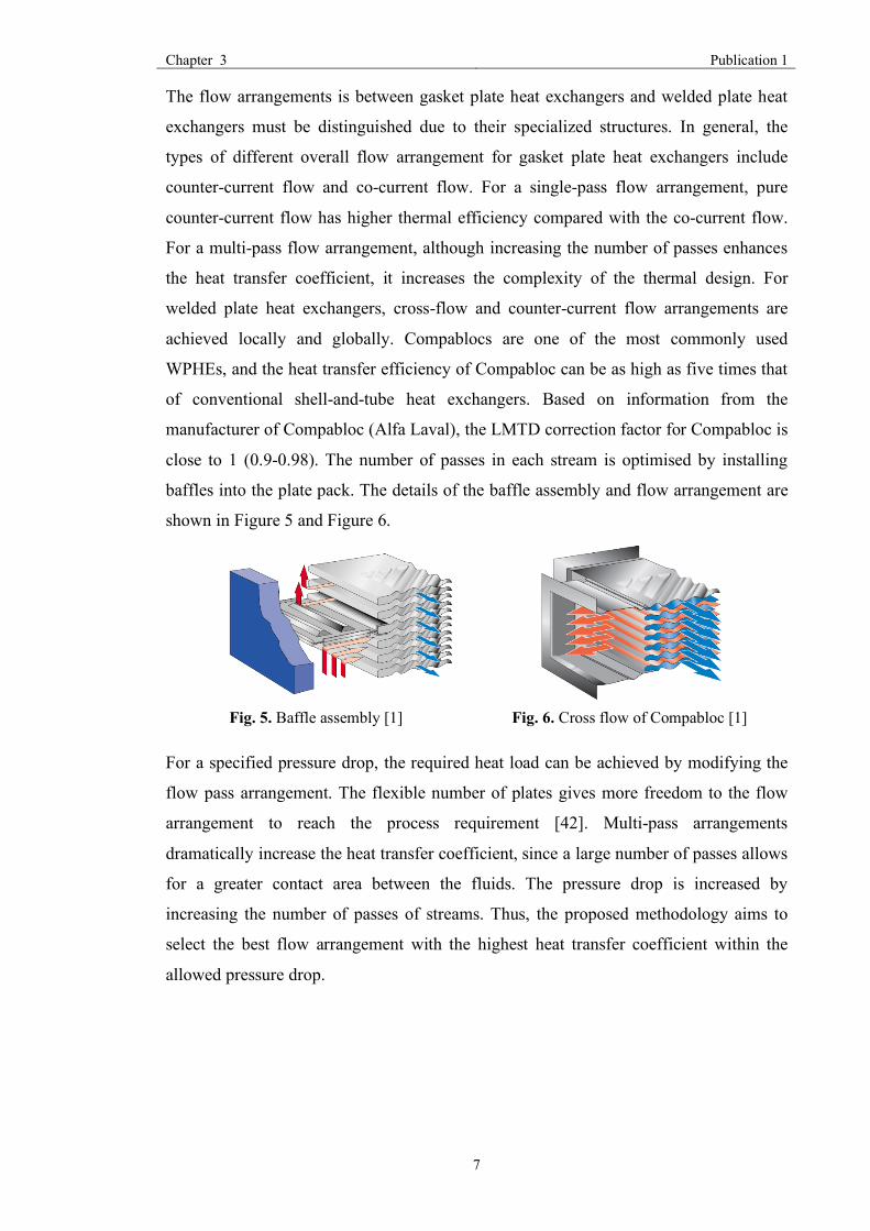
Chapter 3 Publication 1
7
The flow arrangements is between gasket plate heat exchangers and welded plate heat
exchangers must be distinguished due to their specialized structures. In general, the
types of different overall flow arrangement for gasket plate heat exchangers include
counter-current flow and co-current flow. For a single-pass flow arrangement, pure
counter-current flow has higher thermal efficiency compared with the co-current flow.
For a multi-pass flow arrangement, although increasing the number of passes enhances
the heat transfer coefficient, it increases the complexity of the thermal design. For
welded plate heat exchangers, cross-flow and counter-current flow arrangements are
achieved locally and globally. Compablocs are one of the most commonly used
WPHEs, and the heat transfer efficiency of Compabloc can be as high as five times that
of conventional shell-and-tube heat exchangers. Based on information from the
manufacturer of Compabloc (Alfa Laval), the LMTD correction factor for Compabloc is
close to 1 (0.9-0.98). The number of passes in each stream is optimised by installing
baffles into the plate pack. The details of the baffle assembly and flow arrangement are
shown in Figure 5 and Figure 6.
For a specified pressure drop, the required heat load can be achieved by modifying the
flow pass arrangement. The flexible number of plates gives more freedom to the flow
arrangement to reach the process requirement [42]. Multi-pass arrangements
dramatically increase the heat transfer coefficient, since a large number of passes allows
for a greater contact area between the fluids. The pressure drop is increased by
increasing the number of passes of streams. Thus, the proposed methodology aims to
select the best flow arrangement with the highest heat transfer coefficient within the
allowed pressure drop.
Fig. 6. Cross flow of Compabloc [1]
Fig. 5. Baffle assembly [1]

Chapter 3 Publication 1
8
Fig. 7. The six parallel blocks in a multi-pass plate heat exchanger
As mentioned above, the thermal design of PHEs is more complex when multi-pass
flow arrangements are considered. An approach to this problem will now be developed.
To obtain a minimum heat transfer area, the optimization process is not straightforward.
The key point for calculating overall heat transfer coefficient is to separate multi-pass
the PHE into parallel blocks, which are assumed to be single-pass PHEs. Pure co-
current or counter-current flow arrangement is achieved in each block, and the
traditional thermal design method can be further applied to each block.
Consider an Xh-Xc multi-pass plate heat exchanger, in which Xh and Xc represent the
number of passes for the hot side and cold side respectively, the total number of blocks
N is calculated as Xh·Xc. Figure 7 illustrates that an example of a multi-pass PHE
separated into six single-pass blocks with three passes on the hot side and two passes on
the cold side. Among the six parallel blocks, it can be seen from Figure 7 that Block
1,2,4 are counter-current flow, and Block 3,5,6 are co-current flow. The logarithmic
mean temperature difference (LMTD) method is then applied to each single PHE to
obtain thermal-hydraulic performance of the entire heat exchanger. Setting up linear
expressions of inlet and outlet temperatures of process fluids among blocks is one of the
most important steps in the thermal design.
For practical applications, the number of passes for each stream cannot exceed four. In
combination, the total number of different types of flow arrangement is 16. To reduce
the number of integer variables and further decrease computation time, each of these 16
different flow arrangements is treated as an independent optimization process. To
compare different flow arrangements, enumeration technology is applied to select the
best flow arrangement with the minimum total area of PHE.
2.1.2 Plate pattern selection
As the most efficient type of plate [43], the chevron plate is employed for the further
optimization process. The structure of a chevron plate is shown in Figure 8. The plate

Chapter 3 Publication 1
9
effective length Lp, plate width W, port diameter dport, chevron angle 𝛽 are the most
important parameters in a chevron-plate design that influence energy efficiency.
Fig. 8. Structure of chevron plate
Although key geometries of the plate can be set as continuous variables, when
designing a chevron plate, the number of available sets of plates is limited in practical
application. Only the available plate geometries from industrial manufactures are
considered for the further optimization process. The proposed method will
automatically choose the best-standardized plate size with the highest heat transfer
coefficient from Alfa Laval options. Table 1 summarises the most widely used plate
types for PHEs with detailed geometries, including plate width, plate length, equivalent
diameter, and other important plate parameters. Since the plate geometries are integers,
an MINLP model is formulated to select optimal plate type. This increases the difficulty
of searching for the global optimum plate pattern and the optimization workload.
Table 1. The detailed geometries of five different plate types[3]
Plate type δ, mm de, mm W, mm Ab, m2 dport, mm
fch×103, mm Lp, mm
M3 2.4 4.8 100 0.03 36 0.240 320
M6 2.0 4.0 216 0.15 50 0.432 694
M6M 3.0 6.0 210 0.14 50 0.630 666
M10B 2.5 5.0 334 0.24 100 0.835 719
M15B 2.5 5.0 449 0.62 150 1.123 1381
*δ is the gap between plates, de is the equivalent diameter, W is the width of plate, Ab is the area
of single plate, fch is the cross-section area, Lp is the effective length.
As mentioned above, heat transfer behavior is sensitive to chevron angles. Thus, the
detailed design methodology includes three types of channels with different chevron
angle and directly links them with the Nusselt number, as shown in empirical Equation
1 [3].
Nu = m ∙ Re� ∙ PrK.� ∙ S ���UK.<�
(1)

Chapter 3 Publication 1
10
The parameters m and s change with different plate type and channel type. Table 2 lists
the values of the two parameters under different situations, which are from Alfa Laval.
Pr is the Prandtl number, µis viscosity the bulk fluid and µ�is the viscosity at the wall.
Counting chevron angles and plate types presents 15 different combinations in total. To
derive an optimal solution from those combinations automatically, we introduce binary
variable sec(PT, CA) to select plate type and chevron angle, where PT and CA are the
abbreviations of plate type and chevron angle. To select the optimal combination with
maximum heat transfer coefficient and minimum surface area of PHE, the following
equation is obtained:
∑ sec(PT, CA) = 1 (2)
In this equation, the value was 1 if selected and 0 otherwise.
Table 2. Parameter of different plate type and channel type from Alfa Laval [3]
Plate type
M3 M6 M6M M10B M15B
Channel type
H L M H L M H L M H L M H L M
m 0.265 0.12 0.18 0.25 0.12 0.165 0.27 0.11 0.14 0.224 0.126 0.117 0.26 0.085 0.13
s 0.7 0.7 0.7 0.7 0.7 0.7 0.7 0.71 0.73 0.713 0.693 0.748 0.7 0.74 0.74
For the welded plate heat exchanger, the plate pattern selection is slightly different.
According to Alfa Laval, the chevron angle used in Compobloc is a 45° angle with a 5
mm pressing depth. Thus, only the M type channel can be used in WPHE design.
2.1.3 Thermal-hydraulic model
As mentioned previously, this proposed approach applies the LMTD method in term of
the thermal design. The general equations to calculate surface area A of PHEs is [5]:
𝐴 = jx∆0¡¢
(3)
For multi-pass PHEs, A is also related to the number of plates in each block, which can
be expressed as:
𝐴 = 𝑛𝐴£
Where 𝑄 is the total heat transfer load, 𝑈is the overall heat transfer coefficient, ∆𝑇¤¥ is
logarithmic mean temperature difference, n is number of blocks.
Considering the fouling issues, U is expressed as:
𝑈 = <1H1� 1H3�¦§¨§
��© (4)
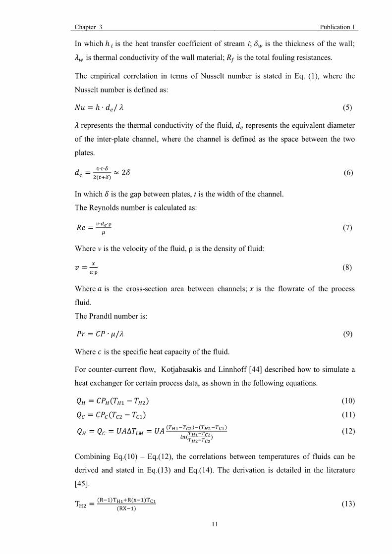
Chapter 3 Publication 1
11
In which ℎMis the heat transfer coefficient of stream i; 𝛿¬ is the thickness of the wall;
𝜆¬ is thermal conductivity of the wall material; 𝑅® is the total fouling resistances.
The empirical correlation in terms of Nusselt number is stated in Eq. (1), where the
Nusselt number is defined as:
𝑁𝑢 = ℎ ∙ 𝑑~/𝜆 (5)
𝜆 represents the thermal conductivity of the fluid, 𝑑~ represents the equivalent diameter
of the inter-plate channel, where the channel is defined as the space between the two
plates.
𝑑~ =�∙°∙±=(°�±)
≈ 2𝛿 (6)
In which 𝛿is the gap between plates, t is the width of the channel.
The Reynolds number is calculated as:
𝑅𝑒 = ´∙Iµ∙⍴¶
(7)
Where v is the velocity of the fluid, ⍴ is the density of fluid:
𝑣 = po∙⍴
(8)
Where𝑎 is the cross-section area between channels; 𝑥 is the flowrate of the process
fluid.
The Prandtl number is:
𝑃𝑟 = 𝐶𝑃 ∙ 𝜇/𝜆 (9)
Where 𝑐 is the specific heat capacity of the fluid.
For counter-current flow, Kotjabasakis and Linnhoff [44] described how to simulate a
heat exchanger for certain process data, as shown in the following equations.
𝑄º = 𝐶𝑃º(𝑇º< − 𝑇º=) (10)
𝑄F = 𝐶𝑃F(𝑇F= − 𝑇F<) (11)
𝑄º = 𝑄F = 𝑈𝐴∆𝑇¤¥ = 𝑈𝐴 (0»120�3)2(0»320�1)
¼q(8»1½8�38»3½8�3)
(12)
Combining Eq.(10) – Eq.(12), the correlations between temperatures of fluids can be
derived and stated in Eq.(13) and Eq.(14). The derivation is detailed in the literature
[45].
T¾= =(¿2<)ÀÁ1�¿(�2<)ÀÂ1
(¿Ã2<) (13)

Chapter 3 Publication 1
12
TÄ= =(�2<)ÀÁ1�(<2¿�)ÀÂ1
(¿�2<) (14)
R = ÄÅÂÄÅÁ
(15)
x = exp �ÆÇ(¿2<)ÄÅÈ
� (16)
Where CP¾is the heat capacity flowrate for the hot stream, CPÄis the heat capacity flow
rate of the cold stream,T¾< and T¾= are the inlet and outlet temperatures of the hot
stream, TÄ< and TÄ= are the inlet and outlet temperatures of cold stream respectively. R
represents the ratio of flow heat capacity of cold and hot streams. Eq. (17) and Eq. (18)
list correlations among inlet and outlet temperatures of the hot and cold side. These
equations are derived by following the same procedure as mentioned before.
T¾= =¿��¿���
T¾< +¿�2¿¿���
TÄ< (17)
TÄ= =�2<�¿��
T¾< +¿��<¿���
TÄ< (18)
x = exp �ÆÇ(¿2<)ÄÅÈ
� (19)
By combining Equation (1) - (19), the heat transfer area A for single-pass PHEs co-
current or counter-current flow can be derived for different plate geometries.
For multi-pass PHEs, the key point of the design is to find the relationships among
temperatures in the adjacent blocks by applying the LMTD method. In each single
block, by employing the above equations the temperatures of streams in any block is
linked with the temperatures of streams in its neighboring blocks. In the case that
several streams with different temperatures enters the same block, the temperature can
be regarded as the average temperature of these streams. Therefore, a systematic linear
relation of temperatures in the different blocks can be set up. Since the entire PHE is
separated into N blocks, the total area of PHE Atotal is equal to N·A.
Pressure drop performance is significantly affected by the plate geometries and the
number of passes of each stream. Thus, the hydraulic and thermal performance of plate
heat exchangers needs to be included in the optimal design simultaneously. To achieve
better heat transfer performance, the pressure drop is preferred to be maximized within
the allowance.
The pressure drop is expressed as:
∆PÉÊËÌÍËÎ5 =�ÉÏ3ÐÑ=ÒÓÔÇÕ
3 (20)

Chapter 3 Publication 1
13
In which f represents the Fanning friction factor, and the expression for f is shown in
the Eq. (21) [46], LP is plate length for pressure drop. The chevron angle and
intermediate variable 𝑓<, 𝑓K affect the Fanning friction factor. The intermediate variable
is determined by the Reynolds number.
<Ö®= ÌÎ�×
ÖK.K�Ø ÍÙ5 ×�K.KÚ �Ë5 ×�®Z/ ÌÎ�×+ <2ÌÎ�×
ÖÛ.Ü®1 (21)
WhenRe ≫ 2000,
fK =<�
f< =<�ڿ�+ 0.9625
WhenRe < 2000,
fK = (1.56 lnRe − 3)2= f< =Ú.èØ
¿�Z.3éê
To account for the different expressions of fK and f<, a binary variable is introduced to
define the different range of Reynolds number.
The other part of the pressure drop comes from the height change, which is defined as:
∆Pë�ËìëÍíρgH (22)
Where ρ is the density of the fluid, g is the acceleration due to gravity, H is the
equivalent height of fluid passing through. However, since the height of a PHE is
comparably small, ∆PÉÊËÌÍËÎ5 can be regarded as the total pressure drop of PHEs.
Because it has been assumed that there is no maldistribution of flow in different
channels, the pressure drop in the channels is equal. Thus, the total pressure drop is
expressed as:
∆P = NP�Ù�� (23)
2.2 Optimization model of plate heat exchangers
For the optimization process, the optimal solution should not only meet the process
requirements but also consider the economics [47]. As shown in Eq. (24) [48], there is a
direct relation between capital cost and total area of PHE. The objective of this
proposed method is to minimize the heat transfer area in a multi-pass plate heat
exchanger.
𝑇𝑜𝑡𝑎𝑙𝑐𝑜𝑠𝑡 = 2.5 ∗ 2070 ∗ 𝐴°W°o¼K.ÜØ (24)
To obtain the optimal solution for a single multi-pass PHE, a mixed-integer non-linear
programming (MINLP) problem is formulated and solved with the ANTIGONE solver

Chapter 3 Publication 1
14
in GAMS. ANTIGONE is one of the most widely used global solvers for MINLP
optimization [49]. To minimize the total area of a PHE, the general problem is shown in
Eq.(25). Among all the variables, the integer variables include the total number of plates
in each block, the number of passes for the cold and hot side, plate geometries and
chevron angle. There are two constraints. One constraint is that the total heat load
should be not less than the required heat load, since the area of the plate is an integer.
The other one is that pressure drop should be maintained in the allowable range.
Fig. 3. Overall design algorithm of plate heat exchangers
Minimize:Ažó = f(Xë, XÌ, β, n, δ, 𝑑~, 𝐴£, 𝐿�)
Subject to Q ≥ QK (25)
ΔP ≤ ΔPÏÙ�
Where Ažó is the total area of the PHE, β is the chevron angle, n is the number of
plates in each block, δ is the gap between plates, de is the equivalent diameter, Ab is the
area of each single plate, QK is process heat transfer requirement, and ΔPÏÙ� is the
maximum pressure drop allowance.
The overall algorithm of the new optimization method for the design of single multi-
pass plate heat exchangers is shown in Figure 9. After extracting the specific operating
conditions and physical properties from the required design process, the first step is to
select a certain flow arrangement k. Also, the local minimum heat exchanger area can
Data extraction (operation condition & physical properties)
Select flow arrangement k
Determine heat capacity ratio R and number of passes for stream I and j
Apply thermal-hydraulic model and minimize the heat exchanger total area
Find the optimum plate with minimal heat exchanger area
K≥Kmax
Find the optimum plate pattern and calculate total area
Determine heat exchanger dimensions
NO

Chapter 3 Publication 1
15
be derived from automatically selecting the best configurations from all available plate
geometries for a specific pressure drop allowance. This process is repeated for other
different types of flow arrangement and the global optimum result with minimum heat
transfer area of the PHE is obtained by comparing all local optimum results.
3. Case study
3.1 Case study 1: optimal design of gasket plate heat exchanger
3.1.1 Verification of the new design methodology
A case from Arsenyeva [3] is used to verify and test the accuracy of the new
optimization-based design method for gasket plate heat exchangers. The stream
properties data are summarised in Table 3. The cold side distillery wash fluid needs to
be heated from 28°C to 90.5 °C by hot water with the inlet temperature of 95°C.
TheΔPÏÙ� for both sides is 1.0 bar.
Table 3. The stream properties of cold side and hot side
Cold side Hot side Units
Flow rate 5 15 m3/h
Inlet temperature 28 95 °C
Target temperature 89 79.36 °C
Density 978.4 960 kg/m3
Viscosity 15.03 0.297 cP
Thermal conductivity 0.66 0.68 W/m K
Heat capacity 3.18 4.21 kJ/kg K
The key point of verification is to fix plate patterns as M6M and keep the numbers of
chevron angle the same as the literature [3]. The comparison of results between the
basic design method [3] and new proposed method with fixed plate pattern are given in
Table 4. When applying the proposed design methodology, the results imply the
minimum heat transfer area of PHE is 5.04 m2 with 38 plates in M channel and the
number of passes for the hot stream and cold streams is 2 and 4 respectively. It is
concluded that the results are consistent with the literature [3] for a fixed plate pattern.
Having validated the new proposed design model, it will further applied in the
optimization process of a single multi-pass PHE design.

Chapter 3 Publication 1
16
Table 4. The comparison of fixed pattern design between literature [3] and proposed method
3.1.2 The computer-aided optimization process of a multi-pass GPHE design
The same case study as Section 3.1.1 is used to apply the new optimization design
method of a single multi-pass GPHE. The optimization process is executed in GAMS
with the ANTIGONE solver. The computation time is only 1.5 minutes for the
optimization process for a particular flow arrangement. However, it takes more than 10
minutes to derive the solution in the published literature [3].
Table 5. The optimization results of a multi-pass GPHE design
Flow arrangement 1-1 2-1 3-1 4-1 1-2 2-2 3-2 4-2
Plate type M6 M10B M6 M15B M10B M6 M10B M6M
Number of plates 60 136 135 36 34 44 30 64
Total area (m2) 8.76 32.64 21.00 22.32 8.09 6.60 7.20 8.96
Flow arrangement 1-3 2-3 3-3 4-3 1-4 2-4 3-4 4-4
Plate type M6M M6 M6M M10B M10B M6 M6 M10B
Number of plates 39 30 39 24 84 32 36 32
Total area (m2) 5.46 4.50 5.46 5.76 19.6 4.80 5.4 7.68
Table 5 shows the optimization results for design of a GPHE under different flow
arrangements. The results imply that the flow arrangement 2-3 gives the minimum heat
transfer area of 4.5 m2 within the required heat load and pressure drop allowance. The
Flow arrangement
1-1 2-1 3-1 4-1 1-2 2-2 3-2 4-2
Plate type M6M M6M M6M M6M M6M M6M M6M M6M
Basic design: Total area (m2)
7.56 32.34 21.7 35.48 9.8 6.58 8.26 8.68
New design: Total area (m2)
7.56 32.34 21.7 35.48 9.8 6.58 8.26 8.68
Flow arrangement
1-3 2-3 3-3 4-3 1-4 2-4 3-4 4-4
Plate type M6M M6M M6M M6M M6M M6M M6M M6M
Basic design: Total area (m2)
5.88 6.58 5.74 6.72 8.54 5.04 6.44 6.72
New design: Total area (m2)
5.88 6.58 5.74 6.72 8.54 5.04 6.44 6.72

Chapter 3 Publication 1
17
optimal solution is achieved by using 30 M6 type of plates. By comparison, Arsenyeva
et al. [3] obtained the minimum area of 5.04 m2 with 38 plates to satisfy the same
process requirement. The heat transfer area can be reduced by 10.71% by the proposed
method. The reason why there is a difference between the proposed method and
literature is due to the round-up process to find the minimum number of plates in each
block. Differences between the heat transfer equations, between the LMTD and ϵ-NTU
methods for thermal design for a multi-pass gasket PHE and the effect of locations of
the inlet fluids on process behavior are other possible reasons that differences in the
differences. Therefore, the optimization solutions obtained within the required process
constraints illustrate the capability of the proposed method to give a feasible global
result with higher energy efficiency. The proposed method significantly decreases the
computation time from several hours to 20 minutes for the entire optimization work of
plate heat exchanger design.
3.2 Case study 2: optimization design of welded plate heat exchanger
This case study from the literature [50] was studied to provide insights into the
application of the proposed method into a welded plate heat exchanger design. A pump
around stream and crude oil from the hot end of the pre-heat train are the two process
streams in this case. The physical properties data of crude side and hot side are listed in
Table 6.
Table 6. A case study from the pre-heat train
Crude side Hot side Units
Flow rate 36.4 64.5 kg/s
Inlet temperature 172 306 °C
Target temperature 260 260 °C
Density 700 733 kg/m3
Viscosity 0.44 0.12 cP
Thermal conductivity 0.1 0.12 W/m K
Heat capacity 2610 2820 J/kg K
The optimized area of a multi-pass welded plate heat exchanger under a different flow
arrangement with optimal plate type are listed in Table 7. The optimization results show
that the minimum area is 25.92m2, which is achieved by a X1=2 and X2=3 flow
arrangement. The total number of plates is 108, and the corresponding plate type is
M10B with the spacing of plates δ = 2.5mm.

Chapter 3 Publication 1
18
The second-best solution is achieved at X1=3, X2=2 with M6 type plates. The spacing
of plates is δ = 2mm, which is smaller than the spacing of M10B type of plate. For
practical considerations, the optimal solution depends on the size of the area, piping
arrangement, the volume of the instalment. Thus, design engineers can choose among
the best solutions based on the different requirements.
Table 7. The optimization results of a multi-pass welded plate heat exchanger design
The flow rate of process fluids are two important indicators that can test whether the
design is robust or not [45]. In the current design methodology, the flow rates of the
cold side and hot side are fixed. To investigate the influence of flow rate on model
output, sensitivity analysis is an effective method [10]. Thus, a sensitivity analysis is
carried out by adjusting the flow rates for both hot side and cold side. In the meantime,
keeping the flow arrangement as X1=1 and X2=1 reduces the complexity of the model
and saves computation time. The results of a sensitivity analysis by varying the flowrate
of the hot and cold side in the range of ±50% are listed in Table 8 and Table 9. The
results show that when the flow rate of the hot stream decreases from 51.6 kg/s to 45.15
kg/s, the plate type changes from M15B to M6. According to the analysis results, the
parameter has a significant impact on the result. Thus, it can be concluded that the
optimal design is robust to ±20% flow of the hot stream but much more robust for the
flow of the cold stream.
Flow arrangement 1-1 2-1 3-1 4-1 1-2 2-2 3-2 4-2
Plate type M15B M10B M15B M15B M6 M10B M6 M6M
Number of plates 58 542 174 188 378 136 210 288
Total area (m2) 35.96 130.08 107.88 116.56 56.7 32.64 31.5 40.32
Flow arrangement 1-3 2-3 3-3 4-3 1-4 2-4 3-4 4-4
Plate type M10B M10B M6M M6 M10B M6M M15B M10B
Number of plates 258 108 575 480 200 256 72 208
Total area (m2) 61.92 25.92 80.5 72 48 35.84 44.64 49.92

Chapter 3 Publication 1
19
Table 8. Sensitivity analysis of the flow rate of hot stream
Table 9. Sensitivity analysis of the flow rate of cold stream
4. Conclusions
A new optimization methodology is proposed to design multi-pass plate heat
exchangers. The main features that determine plate heat exchanger thermal and
hydraulic performance are considered simultaneously by employing discontinuous
expression of Nusselt number and friction factor. The basic plate geometries and the
number of plates are set as integer variables for minimization of total heat transfer area.
The flow arrangement selection is integrated to the thermal-hydraulic model by using
the enumeration method, which simplified the optimization workload and saved
computation time. Thus, an MINLP model has been created in GAMS using the
ANTIGONE solver by considering standardised plate size and the unique heat transfer
and pressure drop performance for different plate patterns.
Two case studies from the literature show the success of applying the proposed design
methodology to the gasket and welded plate heat exchangers. Minimum heat exchanger
area can be achieved for a given heat load. The case studies demonstrate that heat
transfer area can be reduced by 10.71% compared with previously published solutions.
Percentage
-50% -40% -30% -20% -10% 0 10% 20% 30% 40% 50%
Flow rate 32.25 38.7 45.15 51.6 58.05 64.5 70.95 77.4 83.85 90.3 96.75
Plate type
type
M6 M6 M6 M6 M15
B
M15B M15B M15B M15B M15B M15B
Number of plates
plaplates
90 115 159 203 54 58 63 112 250 581 1800
Total area (m2) 13.5 17.25 22.5 30.45 33.48 35.96 39.06 69.44 155 360.22 1116
Percentage
(%)
-50% -40% -30% -20% -10% 0 10% 20% 30% 40% 50%
Flow rate 18.2 21.84 25.48 29.12 32.76 36.4 40.04 43.68 47.32 50.96 54.6
Plate type
type
M15B M15B M15B M15B M15B M15B M15B M15B M15B M15B M15B
Number of plates ppplplapates
90 115 159 203 54 58 63 112 250 581 1800
Total area (m2) 13.5 17.25 22.5 30.45 33.48 35.96 39.06 69.44 155 360.22
1116

Chapter 3 Publication 1
20
Nomenclature
Abbreviation
PHE plate heat exchanger
GPHE gasket plate heat exchanger
WPHE welded plate heat exchanger
LMTD logarithmic mean temperature difference
NTU number of transfer units
MINLP mixed integer nonlinear programming
Re Reynold number
Nu Nusselt number
Pr Prandtl number
Symbols
Lp plate length
W plate width
dport port diameter
de equivalent diameter
Ab plate area
fch cross-section area
µ dynamic viscosity
λ heat conductivity
A heat transfer area
N total number of blocks
X number of passes for stream
h heat transfer coefficient
Q heat load
∆TLM logarithmic mean temperature difference
⍴ stream density
v stream velocity in each channel
t width of channel
Rf fouling resistance of streams
g flow rate of the stream
a cross-section area between channels
T temperature
CP heat capacity
R the ratio of flow heat capacities of streams
Chapter 3 Publication 1
21
Atotal total heat transfer area
f friction factor
∆Pheight pressure drop of height change
∆Pfriction pressure drop due to friction
H height
U heat transfer coefficient
Greek symbol
δ inter-plate gap
𝛽 chevron angle
Atotal total area of heat exchanger
Q0 required heat load
Subscript
b block
h hot stream
c cold stream
w wall
1 inlet
2 outlet
max maximum
5. Reference
[1] Klemes JJ, Arsenyeva O, Kapustenko P, Tovazhnyanskyy L. Compact heat
exchangers for energy transfer intensification: low grade heat and fouling mitigation:
CRC Press, 2015.
[2] Sundén B, Manglik RM. Plate heat exchangers: design, applications and
performance: Wit Press, 2007.
[3] Arsenyeva OP, Tovazhnyansky LL, Kapustenko PO, Khavin GL. Optimal design of
plate-and-frame heat exchangers for efficient heat recovery in process industries.
Energy. 2011;36(8):4588-98.
[4] Kakac S, Liu H, Pramuanjaroenkij A. Heat exchangers: selection, rating, and
thermal design: CRC press, 2012.
[5] Shah RK, Sekulic DP. Fundamentals of heat exchanger design: John Wiley & Sons,
2003.
[6] Xu K, Smith R, Zhang N. Design and optimization of plate heat exchanger networks.
Computer Aided Chemical Engineering: Elsevier; 2017. p. 1819-24.

Chapter 3 Publication 1
22
[7] Coletti F, Macchietto S. A dynamic, distributed model of shell-and-tube heat
exchangers undergoing crude oil fouling. Industrial & engineering chemistry research.
2011;50(8):4515-33.
[8] Loyola-Fuentes J, Jobson M, Smith R. Estimation of Fouling Model Parameters for
Shell-side and Tube-side of Crude Oil Heat Exchangers Using Data Reconciliation and
Parameter Estimation. Industrial & engineering chemistry research. 2019.
[9] Wang T, Luan W, Wang W, Tu S-T. Waste heat recovery through plate heat
exchanger based thermoelectric generator system. Applied energy. 2014;136:860-5.
[10] Guo Y, Wang F, Jia M, Zhang S. Modeling of plate heat exchanger based on
sensitivity analysis and model updating. Chemical Engineering Research and Design.
2018;138:418-32.
[11] Mehrabian M. Construction, performance, and thermal design of plate heat
exchangers. Proceedings of the Institution of Mechanical Engineers, Part E: Journal of
Process Mechanical Engineering. 2009;223(3):123-31.
[12] Elmaaty TMA, Kabeel A, Mahgoub M. Corrugated plate heat exchanger review.
Renewable and sustainable energy reviews. 2017;70:852-60.
[13] Yoon W, Jeong JH. Development of a numerical analysis model using a flow
network for a plate heat exchanger with consideration of the flow distribution.
International journal of heat and mass transfer. 2017;112:1-17.
[14] Mota FA, Ravagnani MA, Carvalho E. Optimal design of plate heat exchangers.
Applied Thermal Engineering. 2014;63(1):33-9.
[15] Abu-Khader MM. Plate heat exchangers: recent advances. Renewable and
sustainable energy reviews. 2012;16(4):1883-91.
[16] Amalfi RL, Vakili-Farahani F, Thome JR. Flow boiling and frictional pressure
gradients in plate heat exchangers. Part 1: Review and experimental database.
international journal of refrigeration. 2016;61:166-84.
[17] Hessami M-A. An experimental investigation of the performance of cross-
corrugated plate heat exchangers. Journal of Enhanced Heat Transfer. 2003;10(4).
[18] Khan T, Khan M, Chyu M-C, Ayub Z. Experimental investigation of single phase
convective heat transfer coefficient in a corrugated plate heat exchanger for multiple
plate configurations. Applied Thermal Engineering. 2010;30(8-9):1058-65.
[19] Wang Q-W, Zhang D-J, Xie G-N. Experimental study and genetic-algorithm-based
correlation on pressure drop and heat transfer performances of a cross-corrugated
primary surface heat exchanger. Journal of heat transfer. 2009;131(6):061802.

Chapter 3 Publication 1
23
[20] Shaji K, Das SK. Effect of plate characteristics on axial dispersion and heat transfer
in plate heat exchangers. Journal of heat transfer. 2013;135(4):041801.
[21] Vafajoo L, Moradifar K, Hosseini SM, Salman B. Mathematical modelling of
turbulent flow for flue gas–air Chevron type plate heat exchangers. International journal
of heat and mass transfer. 2016;97:596-602.
[22] Kılıç B, İpek O. Experimental investigation of heat transfer and effectiveness in
corrugated plate heat exchangers having different chevron angles. Heat and Mass
Transfer. 2017;53(2):725-31.
[23] Kumar B, Soni A, Singh S. Effect of geometrical parameters on the performance of
chevron type plate heat exchanger. Experimental Thermal and Fluid Science.
2018;91:126-33.
[24] Hesselgreaves JE. Compact heat exchangers: selection, design and operation: Gulf
Professional Publishing, 2001.
[25] Promvonge P, Tongyote P, Skullong S. Thermal behaviors in heat exchanger
channel with V-shaped ribs and grooves. Chemical Engineering Research and Design.
2019;150:263-73.
[26] Cooper A, Usher JD. Plate heat exchangers, in: Heat Exchanger Design Handbook.
Hemisphere Publishing Corporation; 1983.
[27] Shah R, Focke W. Plate heat exchangers and their design theory. Heat Transfer
Equipment Design. 1988;227:254.
[28] Wang L, Sunden B. Optimal design of plate heat exchangers with and without
pressure drop specifications. Applied Thermal Engineering. 2003;23(3):295-311.
[29] Gut JA, Pinto JM. Optimal configuration design for plate heat exchangers.
International journal of heat and mass transfer. 2004;47(22):4833-48.
[30] Najafi H, Najafi B. Multi-objective optimization of a plate and frame heat
exchanger via genetic algorithm. Heat and Mass Transfer. 2010;46(6):639-47.
[31] Picón-Núñez M, Martínez-Rodríguez G, Lopez-Robles J. Alternative design
approach for multipass and multi-stream plate heat exchangers for use in heat recovery
systems. Heat transfer engineering. 2006;27(6):12-21.
[32] Cocks A. Plate heat exchanger design by computer. TRANSACTIONS OF THE
INSTITUTION OF CHEMICAL ENGINEERS AND THE CHEMICAL ENGINEER.
1969;47(4):C193-&.
[33] Kumar H. The plate heat exchanger: construction and design. Conference The plate
heat exchanger: construction and design, vol. 86. p. 1275-88.

Chapter 3 Publication 1
24
[34] Zinger N, Barmina L, Taradai A. Design of plate heat exchangers for heat supply
systems. Thermal Engineering (English Translation of Teploenergetika).
1988;35(3):141e5.
[35] Pignotti A, Shah R. Effectiveness-number of transfer units relationships for heat
exchanger complex flow arrangements. International journal of heat and mass transfer.
1992;35(5):1275-91.
[36] Pignotti A, Tamborenea PI. Thermal effectiveness of multipass plate exchangers.
International journal of heat and mass transfer. 1988;31(10):1983-91.
[37] Kandlikar SG, Shah RK. Asymptotic effectiveness-NTU formulas for multipass
plate heat exchangers. Journal of heat transfer. 1989;111(2):314-21.
[38] Tovazhnyanskii L, Kapustenko P, Pavlenko V, Derevyanchenko I, Babak T. The
optimum design of multi-pass dismountable plate heat exchangers. Chemical and
Petroleum Engineering. 1992;28(6):354-9.
[39] Arsenyeva O, Tovazhnyanskyy L, Kapustenko P, Khavin G. Mathematical
modelling and optimal design of plate-and-frame heat exchangers. 2009.
[40] Wright A, Heggs P. Rating calculation for plate heat exchanger effectiveness and
pressure drop using existing performance data. Chemical Engineering Research and
Design. 2002;80(3):309-12.
[41] Arsenyeva OP, Tovazhnyanskyy LL, Kapustenko PO, Khavin GL, Yuzbashyan AP,
Arsenyev PY. Two types of welded plate heat exchangers for efficient heat recovery in
industry. Applied Thermal Engineering. 2016;105:763-73.
[42] Fodor Z, Varbanov PS, Klemeš JJ. Total site targeting accounting for individual
process heat transfer characteristics. Chemical Engineering Transactions. 2010;21.
[43] Kumar V, Tiwari AK, Ghosh SK. Effect of chevron angle on heat transfer
performance in plate heat exchanger using ZnO/water nanofluid. Energy Conversion
and Management. 2016;118:142-54.
[44] Kotjabasakis E, Linnhoff B. Sensitivity tables for the design of flexible processes.
Pt. 1: how much contingency in heat exchanger networks is cost-effective? Chemical
Engineering Research and Design. 1986;64(3):197-211.
[45] Smith R. Chemical process: design and integration: John Wiley & Sons, 2005.
[46] Martin H. A theoretical approach to predict the performance of chevron-type plate
heat exchangers. Chemical Engineering and Processing: Process Intensification.
1996;35(4):301-10.

Chapter 3 Publication 1
25
[47] Taal M, Bulatov I, Klemeš J, Stehlı ́k P. Cost estimation and energy price forecasts
for economic evaluation of retrofit projects. Applied Thermal Engineering.
2003;23(14):1819-35.
[48] Guo K. Optimisation of plate/plate-fin heat exchanger design: University of
Manchester, 2015.
[49] Misener R, Floudas CA. ANTIGONE: algorithms for continuous/integer global
optimization of nonlinear equations. Journal of Global Optimization. 2014;59(2-3):503-
26.
[50] Tamakloe EK, Polley GT, Picón-Núñez M. Design of Compabloc exchangers to
mitigate refinery fouling. Applied Thermal Engineering. 2013;60(1-2):441-8.

Chapter 4 Publication 2
63
Chapter 4
Publication 2: Application of plate heat exchangers in heat
exchanger network retrofit without structure modification
(Xu, K., Akpomiemie, M. O., Smith, R., Application of plate heat exchangers into heat
exchanger network retrofit without structure modification. Energy, submitted)

Chapter 4 Publication 2
1
Application of plate heat exchangers in heat exchanger
network retrofit without structural modifications
Kexin Xu*, Mary O. Akpomiemie, Robin Smith
Centre for Process Integration, Faculty of Chemical Engineering and Analytical
Science, the University of Manchester, Manchester M13 9PL, UK
*Corresponding authors’ email address: [email protected]
Abstract
Heat exchanger networks (HENs) retrofit have received a great deal of attention both in
academic and industrial fields to achieve greater energy savings. Heat transfer
enhancement techniques have been used in HEN retrofit through improving thermal
performance of shell and tube heat exchangers. Compared with conventional methods
such as topology modifications and additional surface area, heat transfer enhancement
can significantly reduce the retrofit cost. However, one of the film coefficients must be
controlling in order to use enhancement techniques economically. Also, heat recovery is
limited with enhancement since it is restricted by the geometry of the existing heat
exchangers. Plate heat exchangers are one of the most efficient types of heat transfer
equipment. Applying plate heat exchanger into the retrofit of HENs is considered as an
alternative option to increase heat transfer coefficient and energy saving in the absence
of structural modifications. Due to the high installation cost of plate heat exchangers, a
systematic optimization it is important to balance the trade-off between energy saving
and economic cost. This paper proposes a novel approach of applying plate heat
exchanger in HENs retrofit with a fixed network structure. The objective is to maximize
the retrofit profit while meeting the heat transfer requirement and keeping the existing
heat transfer area of heat exchangers. A case study highlights the benefits of the new
approach.
Keywords: Plate heat exchanger, heat exchanger network, optimization, energy
consumption
Highlights:
• Allowing small ∆Tmin in the heat exchanger network retrofit

Chapter 4 Publication 2
2
• A cost-effective method is proposed for network retrofit using plate heat
exchangers
• Energy consumption is reduced by applying plate heat exchangers
1. Introduction
With the growth of energy consumption and the increase of CO2 emissions, it is now
more important than ever to improve heat transfer efficiency. HEN retrofit plays an
important role of improving energy efficiency in the process industries since it is a
relative cost-effective compared with a new design. There are two main methods to
achieve heat recovery in a retrofit design, involving adding heat transfer area and
topology (structural) modifications. Implementing these conventional methods in
practice generally leads to high capital cost retrofit resulting from the amount of
pipework and maintenance time [1].
Heat transfer enhancement can be applied in HENs retrofit as a cost-effective
technology since it can directly increase the heat transfer rate of shell and tube heat
exchangers to avoid complex topology modifications and civil engineering work. Shell-
side enhancement and tube-side enhancement are the two main heat transfer
enhancement techniques. However, for heat transfer enhancement, the enhancement
level of heat transfer coefficient is restricted by the geometry of the existing heat
exchanger. Therefore, increasing heat recovery is further limited due to the constraint of
the exchanger geometry. Besides, in order to use enhancement technique efficiently,
typically as least 50% of overall heat transfer resistance of either tube-side film
coefficient or shell-side heat transfer coefficient must be from one of the film
resistances, which means that applying heat transfer enhancement requires the
controlling side of the exchanger to be addressed.
Rather than use heat transfer enhancement, other types of high-efficiency heat
exchangers can be considered for HEN retrofit. Plate heat exchangers, including gasket
plate heat exchangers and welded plate heat exchangers, are amongst the most high-
efficiency heat transfer devices. The hot and cold streams flow through alternate
channels between plates and transfer heat through the metal plates. Compared with
conventional shell and tube heat exchangers, plate heat exchangers are able to
dramatically improve energy efficiency with minimum approach temperature as low as
2 °C, leading to reduced utility consumption and CO2 emissions. Owing to the relatively
small hydraulic diameter, the turbulence flow enhances the local convective heat

Chapter 4 Publication 2
3
transfer coefficient. For a given duty, the surface area of a plate heat exchanger is
significantly smaller than the area of a conventional shell and tube heat exchanger.
Based on these features, this work aims to show the insight of integrating plate heat
exchangers and shell and tube heat exchangers into HENs retrofit and improving the
energy performance of an existing heat exchanger network.
Established techniques and methodologies for the retrofit of HENs focus on modifying
the existing HENs to obtain energy savings and overcome network bottlenecks. There
are three main retrofit methods for existing HENs, including Pinch analysis,
mathematical programming and hybrid methods. There are several reports in the
literature dedicated to the retrofit of HENs based on these methods. Sreepathi and
Rangaiah[2] presented detailed review of existing methods for HEN retrofit. Smith [3]
introduces the fundamentals of energy targets, capital and total cost targets, and network
design of HENs. Pinch Analysis for retrofit makes use of a targeting stage for
estimating the maximum energy recovery of a network, and re-design stage to
disconnect and reconnect the cross-pinch exchangers to obey the pinch decomposition.
Tjoe and Linnhoff [4] first introduced a retrofit method based on Pinch Analysis. The
objective of the work was to eliminate heat transfer across the pinch. The cost of the
retrofit design of existing HEN has been further considered by Carlsson et al. [5].
Gadalla [6] presented a graphical method, in which the potential modifications were
identified to achieve maximum heat recovery. However, Pinch Analysis requires an
expert user for its application in retrofit and fails to identify the number of heat
exchangers to modify and the appropriate placement for the additional heat transfer area
requirement. Also, Pinch Analysis requires too many changes in a single step, which
makes it fundamentally not suited to retrofit. Instead of accepting the features that
already exist, it tries to convert the existing network into an ideal grass root design in a
single step.
To achieve completely automatic optimization, the retrofit design of HEN is formulated
to a mathematical optimization model. To identify the most cost-effective design from
many possible retrofit solutions embedded in a superstructure, Grossman [7] formulated
a mixed integer non-linear programming (MINLP) model for the retrofit design of an
existing HEN. Ciric and Floudas [8] presented a superstructure approach for retrofit of
HENs. First, the paring of all possible matches and heat exchangers were evaluated and
decisions regarding selecting matches, reassigning heat exchangers, adding new heat
exchangers and piping work streams made. Based on the results obtained from the first

Chapter 4 Publication 2
4
stage, the optimization of the superstructure design was developed containing all
structural features of an existing HEN to remove all unnecessary features and minimize
the cost. How to obtain a local optimum solution is the main challenge to solve the
MINLP problem. Many methods have been proposed to decompose the retrofit
problem. A constant approach temperature model was presented by Ma et al. [9] to
linearize the area calculations. Yee and Grossman [10] developed a two-stage retrofit
method. An MINLP model was developed in the pre-screening stage, and a NLP model
was built in the optimization stage. Stochastic optimization, which is proposed by Dolan
[11], was another method to decompose the retrofit problem. One of the significant
advantages of mathematical programming is that both of the total cost and energy
saving for the retrofit can be considered in the optimization process at the same time
[12]. Compared to the Pinch Analysis method, mathematical programming allows the
retrofit design of HENs to be automated and to consider more variables. However, the
mathematical programming method is very sensitive to the initial points and requires
relatively long computation times.
A hybrid method for the retrofit design of HEN was proposed by Asante and Zhu [13],
which is referred to as the Network Pinch Approach. The method was separated into
stages: diagnosis stage and optimization stage. In the first stage, they assumed a
minimum approach temperature and identified the possible structural modification
based on an MILP model with maximum heat recovery. The optimization stage makes
use of an NLP model to optimize the capital-energy trade-off of the structural
modifications determined in the first stage. The sequential approach enables the
automation of the design procedure, while maintaining user interaction. The Network
Pinch Approach was modified by Smith et al. [14] with consideration of structural
modifications and capital-energy optimization in a single step. To consider some
practical features, Bakhtiari and Bedard [15] further improved the approach by using a
modified Network Pinch approach to increase the possibility of identifying cost-
effective design solutions. Structural modifications are the only possible method to
overcome the Network Pinch in order to achieve greater energy saving. Resequencing
heat exchangers, stream splitting, and adding new heat exchangers are the three main
methods used for improving energy saving. The main limitation of Network Pinch
Approach is that only one change at a time can be made in the network with the
automated sequence. It is difficult to identify the best modification series in the retrofit
design of an existing HEN. So, it is possible that the retrofit selection option in early
stages prevents obtaining the optimal solution in the final stage.

Chapter 4 Publication 2
5
In recent years, there has been an increased amount of work applying heat transfer
enhancement techniques in HEN retrofit. Adding inserts and fins in the existing heat
exchangers, which can increase the heat transfer coefficient and effective geometrical
area, are the two main techniques in heat transfer enhancement. Heat transfer
enhancement increases heat recovery and can also reduce energy consumption.
Additionally, compared with conventional retrofit strategies it is a relatively low cost
retrofit option without modifying topologies. Pan et al. [16] proposed an optimization
method which focused on the systematic implementation of heat transfer enhancement
in retrofit without topology modifications. The exact value of log mean temperature
difference, correlation factor FT and multiple passes are considered in the optimization
procedure. However, this method is restricted to small-scale problems. A novel MILP
based iterative method was proposed by Pan et al. [17] to retrofit HEN with the help of
heat transfer enhancement. Although this method overcame the drawbacks of existing
design methods, it failed to provide an insight into how to find the best heat exchangers
to enhance. In addition, the uncertainty caused by simplification was not considered. To
solve these problems, a heuristic-based method has been proposed by Wang et al. [18].
This work identified the amount of energy saving and positions of the candidate heat
exchanger to enhance based on sensitivity analysis. However, this work failed to
guarantee the feasibility of the required heat transfer enhancement. Jiang et al. [19]
extended the approach to consider accurate modelling of the chosen enhancement
technique to ensure an accurate representation of proposed energy savings.
Akpomiemie and Smith [1] developed a new model to apply heat transfer enhancement
through extending the both methodologies to consider the downstream effects on the
network. Nevertheless, to use heat transfer enhancement effectively, one of the film
coefficients must be controlling. Furthermore, although heat transfer enhancement
techniques can be performed during the normal shutdown time, the potential risk of
damaging the heat exchangers when adding inserts or fins is not negligible. Therefore,
to break the bottleneck of existing exchanger geometries, this research proposes a novel
retrofit approach by applying plate heat exchangers into HENs to increase the energy
efficiency and heat recovery. Both physical insights and algorithms are presented in this
work.
The aim of this work is to develop a cost-effective retrofit method for HENs to
maximize retrofit profit by strategically replacing conventional heat exchangers with
plate heat exchangers and allowing different global and local approach temperature in

Chapter 4 Publication 2
6
the network with a fixed structure. This work proposes the concept of integrating two
different types of heat exchangers into HEN retrofit with different minimum approach
temperatures. The proposed method specifies how to identify the most sensitive heat
exchanger to be replaced and how to optimize the cost of plate heat exchangers and
rebalance the network after replacement in order to tackle the downstream effect and
meet the required heat transfer. A case study is used to illustrate the proposed methods
and highlight their potential retrofit benefits by making a comparison between various
retrofit options.
2. Application of plate heat exchangers in HEN retrofit with a fixed structure
In this section, the methodology for the application of plate heat exchanger for HEN
retrofit is demonstrated in detail. The maximum heat recovery of a HEN depends on the
minimum approach temperature. Once the minimum approach temperature is fixed, the
minimum utility consumption is fixed correspondingly according to pinch analysis. The
minimum approach temperature for conventional shell and tube heat exchangers is
generally 10°C or 20°C, depending in the process technology. For plate heat exchangers
this can be decreased to 5°C. Integrating plate heat exchangers into the HEN retrofit
strategy of traditional HENs, requires two different minimum approach temperatures for
the different equipment, increases the potential heat recovery and energy saving.
Figures 1 and 2 present an example of the composite curves of a HEN at different
approach temperature (20 °C and 5 °C) to explain how the minimum approach
temperature relates to energy recovery. It can be clearly seen from the graph that both
the hot utility and cold utility consumption significant decrease at 5°C compared to say
20°C. The heat exchangers near the pinch point are identified as the candidate
exchangers to be replaced due to their relatively low minimum approach temperature.
However, this figures only shows some guides about potential heat recovery and the
approximate region to choose the candidate heat exchanger with the most appropriate
benefit in terms of energy saving. The following part will introduce the step-by-step
procedures of integrating a plate heat exchanger network with conventional shell and
tube heat exchangers into retrofit design, which involves different approach
temperature.
This work proposes a method to deal with two different minimum approach temperature
caused by different types of heat exchangers. The minimum approach temperature of
conventional shell and tube heat exchangers should be higher than the existing
minimum approach temperature in the network. The minimum approach temperature of

Chapter 4 Publication 2
7
plate heat exchanger should be higher than 5°C. Thus, two constraints are introduced as
the Equation (1) and (2).
∆𝑇M ≥ 𝐸𝑥𝑖𝑠𝑡𝑖𝑛𝑔∆𝑇nMq𝑖𝜖𝑆&𝑇𝐻𝑋 (1)
∆𝑇" ≥ 5℃𝑗𝜖𝑃𝐻𝐸 (2)
Figure. 1. Composite curves at 20°C
Figure. 2. Composite curves at 5°C
For the retrofit of HENs using plate heat exchangers, the steps include, identifying the
best candidate heat exchanger require to replace, optimization of the new plate heat
exchanger and HEN simultaneously and setting up a non-linear model to rebalance
network. The details of these steps are presented in the following sections.
2.1 Identification of candidate heat exchangers to replace
Candidate heat exchangers are first identified by their location on utility paths. Then
sensitivity analysis is carried out to determine the rank of identified exchangers.
2.1.1 Identification of utility paths [1]
A utility path is a connection between two utilities through process heat exchangers.
Based on an existing HEN, the exchangers to be replaced must be on a utility path so
that heat loads can be shifted along this utility path, which can lead to a cost-effective
retrofit without structural modifications and additional surface area [20]. This work

Chapter 4 Publication 2
8
proposes the use of plate heat exchangers in place of shell and tube heat exchangers in
existing HENs. In addition, utility paths are used to rebalance the HENs after making
modifications since the changes to the HEN impacts the performance of heat exchangers
around the network.
For a simple network, inspection is used to identify the utility paths. However, for a
complex HEN, an Incidence Matrix Approach is carried out to identify utility paths. The
rows in the Incidence Matrix represent all streams in the network and the columns are
exchangers. S represents the number of process and utility streams and E represents the
number of heat exchanger in the existing HEN. The Incidence Matrix Aij describes how
the streams are incident on exchangers.
𝐴M" = $+1𝑖𝑓ℎ𝑒𝑎𝑡𝑒𝑥𝑐ℎ𝑎𝑛𝑔𝑒𝑟𝑗𝑟𝑒𝑚𝑜𝑣𝑒𝑠ℎ𝑒𝑎𝑡𝑓𝑟𝑜𝑚𝑠𝑡𝑟𝑒𝑎𝑚𝑖−1𝑖𝑓ℎ𝑒𝑎𝑡𝑒𝑥𝑐ℎ𝑎𝑛𝑔𝑒𝑟𝑗𝑠𝑢𝑝𝑝𝑙𝑖𝑒𝑠ℎ𝑒𝑎𝑡𝑡𝑜𝑠𝑡𝑟𝑒𝑎𝑚𝑖0𝑖𝑓ℎ𝑒𝑎𝑡𝑒𝑥𝑐ℎ𝑎𝑛𝑔𝑒𝑟𝑗𝑖𝑠𝑛𝑜𝑡𝑖𝑛𝑐𝑖𝑑𝑒𝑛𝑡𝑜𝑛𝑠𝑡𝑟𝑒𝑎𝑚𝑖
A column vector P is added to the incidence matrix. Values of vector P are all zero
except the entries for hot and cold utility, which are +1 and -1 respectively. The key
point of the Incidence Matrix method is that all hot utilities need to be integrated into
one stream and cold utilities also follow the same role.
An example from Li and Chang [21] is shown in Figure 3 to provide an insight into how
to generate the Incidence Matrix and how to identify the utility paths by this method.
According to Figure 3, cold utilities C1 and C2 need to be regarded as one stream,
which means different cold utilities used be considered as one stream. Thus, there are 7
streams and 7 heat exchangers in total.
Figure. 3. Example HEN
Following this method, the initial incidence matrix is formulated, and the values are listed in Table 1.

Chapter 4 Publication 2
9
Table 1. Initial incidence matrix
S/E 1 2 3 4 C1 C2 H P
H1 0 0 +1 0 +1 0 0 0
H2 0 0 0 +1 0 +1 0 0
H3 +1 +1 0 0 0 0 0 0
C1 0 -1 -1 0 0 0 0 0
C2 -1 0 0 -1 0 0 -1 0
HU 0 0 0 0 0 0 +1 +1
CU 0 0 0 0 -1 -1 0 -1
Total 0 0 0 0 0 0 0 0
If the sum values of each column are all equal to zero, then the matrix is linearly
dependent. As it is clearly shown in Table 1, the initial incidence matrix is linearly
dependent. Then, the initial incidence matrix is reduced by making row operations in
order to generate an independent matrix. This is to ensure that all entries below the first
non-zero entry of each row in the matrix are zero. In Table 1, the first non-zero entry of
the first row is Exchanger 3. In Column 3, the first non-zero entry value below row 1 is
in Row 4. Thus, to guarantee this value to be zero, row 1 is added to Row 4. This
procedure is repeated for all rows until all entries below the first non-zero entry of each
row are zero. And the obtained independent matrix and corresponding values are listed
in Table 2.
Table. 2. Independent incidence matrix
S/E 1 2 3 4 C1 C2 H P
H1 0 0 +1 0 +1 0 0 0
H2 0 0 0 +1 0 +1 0 0
H3 +1 +1 0 0 0 0 0 0
C1 0 -1 0 0 +1 0 0 0
C2 0 0 0 0 +1 +1 -1 0
HU 0 0 0 0 0 0 +1 +1
CU 0 0 0 0 0 0 0 0
The column vector P links two utilities with process stream exchangers. The column
vector P is equated to a linear combination of columns in the incidence matrix after the
linearly independent matrix is formulated. The linear combination obeys the enthalpy

Chapter 4 Publication 2
10
balance, which implies the amount of heat load added to a heater must be subtracted
from an exchanger in the path, added to the next exchanger in the path, and so on and
finally added to a cooler in the path. For the existing HEN in Figure 3, the two utility
paths are shown in Figure 4 and 5.
Figure. 4. Utility path: H-4-C2
Figure. 5. Utility path: H-1-2-3-C1
2.1.2. Sensitivity analysis
In this section, sensitive analysis is applied in order to determine the most appropriate
heat exchangers that require to be replaced by plate heat exchangers so that the energy
saving among others can be led. It also makes the selection of the sequence of
replacement easier. The only information required in the sensitivity analysis is the base
case stream data and the HEN structure. Kotjabasakis and Linnhoff [22] were the first to
propose sensitivity analysis. This method is based on the equation:
𝑄 = 𝑈𝐴∆𝑇¤¥𝐹0(3)
In which Q is the total heat load, W; U is the overall heat transfer coefficient,
W/(K·m2); A is the area of the heat exchanger, m2; ∆𝑇¤¥ is the logarithmic mean
temperature difference, K; 𝐹0 is the correction factor. The aim of sensitivity analysis is
to increase the inlet temperature of the key utility, which is identified as the one that has
the largest energy consumption, by adjusting the heat transfer coefficient, surface area

Chapter 4 Publication 2
11
and correction factor of candidate heat exchangers. Wang [23] developed a
mathematical model to identify the high sensitivity heat exchangers, which is identified
as the one that can bring the greatest increase in the inlet temperature of the key utility
exchanger. This study concluded that the amount of energy saving largely depended on
the gap between the heat exchanger and the key utility. Easy implementation and short
computation time are the main advantages of sensitivity analysis.
2.2 Application of plate heat exchangers
The best exchangers identified are replaced with plate heat exchangers. The plate heat
exchanger design model used in this paper is from Xu et al. [24], which considers
effects of multi-pass flow arrangement, plate geometries and chevron angle on heat
transfer behaviour. Then, the exchanger sizing model is formulated to obtain the
maximum heat transfer coefficient, implemented by General Algebraic Modelling
System (GAMS). The input process stream data are derived from candidate heat
exchangers.
To achieve the same amount of heat recovery, the larger heat transfer coefficient, the
smaller heat exchanger area and capital cost will be. Since there is a negative correlation
between plate heat exchanger heat transfer coefficient and capital cost, the minimal
capital cost can be further obtained. The generalized algorithm of optimization of the
heat transfer coefficient is shown in the Figure 6.
Data extraction (operation condition & physical properties)
Select flow arrangement k
Determine heat capacity ratio R and number of passes for stream I and j
Apply thermal-hydraulic model and minimize the heat exchanger total area
Find the optimum plate with minimal heat exchanger area
K≥Kmax
Find the optimum plate pattern and calculate total area
Determine heat exchanger dimensions
NO

Chapter 4 Publication 2
12
Figure. 6. Optimization algorithm of design a single plate heat exchanger
2.3 Optimization of HEN
Application of plate heat exchangers to replace the conventional heat exchangers in the
existing HEN can affect the performance of the other heat exchangers. The heat transfer
coefficient of the new plate heat exchanger is significantly higher, which leads an
increase of the inlet temperature of the next heat exchanger in the hot stream and a
decrease of the inlet temperature of the next heat exchanger in cold stream respectively.
These changes can further affect the other components. To rebalance the HEN, the heat
loads of heat exchangers need to be relocated and shifted through the utility paths. Thus,
an optimization method to retrofit an existing HEN without topology modification is
proposed. Furthermore, the capital cost of plate heat exchanger is still an important
component for total network cost calculation, even if the application of plate heat
exchangers can lead to significant energy saving.
Therefore, there is a trade-off between energy saving and total retrofit cost. In this
optimization model, the objective function is to maximize retrofit profit, which is the
difference between the energy savings and total cost of the retrofit. The total cost of
retrofit consists of the implementation cost of the bypass, the capital cost of plate heat
exchangers, the cost of additional heat transfer area of heat exchangers which are
located on the utility path. The profit from energy saving can be obtained from the total
amount of utility saving. The two main process constraints are achieving the target
temperatures of the process streams and maintaining the existing heat exchanger areas
(excluding the candidate heat exchangers to be replaced).
Objective Function: Maximize Retrofit Profit = Profit from energy saving – Total cost of retrofit
Constraints: Aex = AE ∀exchangers (excluded the candidate heat exchanges)
TTs = TTE ∀streams
Variables: heat load for all exchangers on a utility path
heat transfer coefficient for candidate heat exchanger
3. Case study
The base case is a simplified crude oil preheat train. The new HEN retrofit model is
used to optimize the performance of the base case through applying plate heat
exchangers in a fixed network structure. Figure 6 illustrates the existing HEN for the

Chapter 4 Publication 2
13
base case. There are in total 12 exchangers, 5 hot streams and 1 cold stream. The
objective of this study is to maximize the retrofit profit by applying plate heat
exchangers into the existing network without adding area and structure change. Table 3
summarises the cost parameters used in this study. The streams properties are assumed
to be constant. To quantify the retrofit profit, the operating time is fixed at one year.
Figure. 7. Simplified pre-heat train
Table 3. Cost data for case study
Utility cost data Retrofit cost data
Hot Utility Cost: 400 ($/kW y) Cost of installing of plate heat exchangers: 2.5*2070*A^0.85 ($)
Cold Utility Cost: 5.5 ($/kW y) Implementing By-pass: 5000 ($)
Cost of increasing heat exchanger area: 6000 + 200*A ($)
The first step is to identify the best heat exchanger for replacement. From Figure 6, only
process heat exchanger 7 is not on the utility path. Thus, sensitivity analysis is
performed on heat exchanger 1, 2, 3, 4, 5 and 6. From Figure 7, heat exchanger 5 is the
most sensitive exchanger as it brings the greatest increase in the inlet temperature of the
key utility exchanger. Thus, the heat exchanger 5 is selected to be replaced by a plate
heat exchanger. To maximize retrofit profit, the heat duties of heat exchanger 5 and
corresponding cold utility exchanger 10 are set as variables and rebalance the heat duty
of all the heat exchangers.
The cold utility exchanger is selected as this represents a constraint on the maximum
increase in the duty of heat exchanger 5 without violating the target temperature

Chapter 4 Publication 2
14
requirement. After inputting the process stream data of exchanger 5 into the
optimization model of a single plate heat exchanger in GAMS, the maximum heat
transfer coefficient can be derived with a value of 3.75 kW/m2 ºC, which is a significant
increase compared with shell and tube heat exchangers i.e. 0.32 kW/m2 ºC. Then, the
global solver is used to optimize the case in which optimization procedure is obtained to
rebalance the HEN, implemented on LINDO Systems What’s Best!
Figure. 8. The result of sensitivity analysis
The details of the heat exchanger area, heat transfer coefficient and heat load of each
heat exchangers before and after the retrofit design of the HEN are listed in Table 4.
Table 4. Exchanger details before and after replacement
Exchanger A (m2) Areplacement (m2) U (kW/m2 ºC)
Ureplacement (kW/m2 ºC)
Q (kW) Qreplacement (kW)
1 396.72 396.72 0.45 0.45 6141.33 5522.40 2 545.45 545.45 0.39 0.39 6134.83 6604.64 3 633.85 633.85 0.14 0.14 5556.61 5640.23 4 354.64 354.64 0.09 0.09 2688.79 2680.76 5 183.85 23.83 0.32 3.57 3431.16 4248.10 6 843.73 843.73 0.06 0.06 2291.88 2280.23 7 115.02 115.02 0.36 0.36 3623.20 3623.20 8 - - - - 657.23 722.72 9 - - - - 1141.81 1149.84 10 - - - - 816.94 0.00 11 - - - - 880.62 892.27 12 - - - - 14455.41 13723.76
The heat duty of exchanger 5 is increased by 816.94 kW and the utility consumption in
exchanger 10 decreases to 0. Although the heat load of heat exchanger 5 increases, the
area of exchanger 5 decreases from 183.85 m2 to 23.83 m2 by applying the plate heat
exchanger. 3 bypasses are implemented to reduce the duty of heat exchangers. The
results of retrofit cost and retrofit profit are detailed in Table 5 with the initial utility

Chapter 4 Publication 2
15
cost of $5,801,396. This procedure is repeated until the net saving starts to decrease,
since the retrofit objective is to maximize retrofit profit. According to the sensitivity
analysis, the next heat exchanger to be replaced is heat exchanger 1. The results after
replacement of heat exchanger 5 and heat exchanger 1 are listed in Table 5. The net
saving after replacing heat exchanger 1 is smaller than only replacing heat exchanger 5,
which violates the objective of maximizing the retrofit profit, thus the replacement is
stopped after replacing heat exchanger 5. The main reason that limits the net saving is
the amount of utility saving, which is restricted to the fixed area of heat exchanger 2 and
heat exchanger 3.
Table 5. Retrofit results
Parameter Replace E5 Replace
E5&E1
Replace E5&E1
(allowing extra area on
E2 & E3)
Retrofit Cost
Replacement $76,630 $272,893 $324,287 Increasing Area $0 $0 $199,323
Implementing By-pass $15,000 $15,000 $15,000 Total Cost $91,631 $287,893 $539,110
Retrofit Profit
Utility Savings $296,684 $296,604 $494,325 Net Saving
(Utility Savings –
Total Cost)
$205,054
(~3.5% of initial utility cost)
$8,702
(~0.5% of initial utility cost)
-$44,785
Pay back 0.31 yr 0.97 yr 1.09 yr
Thus, another trial allowing extra area on heat exchanger 2 and 3 is carried out. It can be
clearly seen from Table 5 that the utility saving increases from $296,604 to $494,325.
However, the high capital cost of the plate heat exchanger and high cost of increasing
area leads to an increase in the payback time from 0.97yr to 1.09yr.
The comparisons between the application of plate heat exchanger and heat transfer
enhancement [1] are also highlighted (see Table 6). The retrofit profit of replacement is
$11,218 smaller than that obtained from enhancement because of the high installation
cost of the plate heat exchangers. Nevertheless, in this case the utility saving in
replacement is $59,431 larger than enhancement.
Thus, heat transfer enhancement is a cost-effective retrofit method. However, when one
of the film coefficients is controlling, applying plate heat exchanger to replace shell-
and-tube heat exchanger can be regarded as an alternative option for retrofit, which can
bring more energy saving at the same time.

Chapter 4 Publication 2
16
Table 6. Replacement vs Heat transfer enhancement
Parameter Replacement Enhancement
Retrofit Cost
Replacement $76,630 $3,981 Increasing Area $0 $0
Implementing By-pass $15,000 $15,000 Total Cost $91,631 $18,981
Retrofit Profit Utility Savings $296,684 $237,253 Net Saving $205,054 $216,272
4. Conclusions
A new retrofit method for heat exchanger networks using the integration of plate heat
exchangers and conventional heat exchangers with different minimum approach
temperature has been proposed in this work. The case study highlights the potential
benefit of the new retrofit method with fixed structure. Compared to the traditional heat
transfer enhancement technologies, replacing the shell and tube heat exchangers with
plate heat exchangers can significantly increase the heat recovery and decrease energy
consumption with a smaller heat transfer area. However, the installation cost of the plate
heat exchanger is relatively high. Thus, plate heat exchangers can be used as an
alternative retrofit option when one of the heat transfer films is not controlling.
Applications of plate heat exchangers allow small ∆Tmin in the network. A case study
has been examined to introduce plate heat exchangers into the network with ∆Tmin at
5 °C. Augmenting the existing shell-and-tube heat exchangers is more cost-effective
than the replacement due to the reduced heat load. With fixed structure, the amount of
energy saving is limited. The savings are constrained, as all of the existing matches,
except the new plate heat exchangers, are being maintained at their original sizes.
Nomenclature
Abbreviation
HEN heat exchanger network
PHE plate heat exchanger
MINLP mixed integer non-linear programming
NLP non-linear programming
MILP mixed integer linear programming
GAMS General Algebraic Modelling System

Chapter 4 Publication 2
17
Symbols
∆Tmin minimum approach time
FT correlation factor
Aij matrix of incident streams on exchangers
S number of process and utility streams
E number of heat exchanger in the existing HEN
P column factor was added incidence matrix
C1 cold utility 1
C2 cold utility 2
H1 hot stream 1
H2 hot stream 2
H3 hot stream 3
HU hot utility
CU cold utility
Q heat load
U overall heat transfer coefficient
A surface area of the heat exchanger, m2
∆TLM logarithmic mean temperature difference
k flow arrangement
R the ratio of flow heat capacities of streams
TT target temperature
Chapter 4 Publication 2
18
5. Reference
[1] Akpomiemie MO, Smith R. Retrofit of heat exchanger networks without topology
modifications and additional heat transfer area. Applied energy. 2015;159:381-90.
[2] Sreepathi BK, Rangaiah G. Review of heat exchanger network retrofitting
methodologies and their applications. Industrial & engineering chemistry research.
2014;53(28):11205-20.
[3] Smith R. Chemical process: design and integration: John Wiley & Sons, 2005.
[4] Tjoe TN, Linnhoff B. Using pinch technology for process retrofit. Chemical
Engineering. 1986;93(8):47-60.
[5] Carlsson A, Franck P-A, Berntsson T. Design better heat exchanger network
retrofits. Chemical Engineering Progress;(United States). 1993;89(3).
[6] Gadalla MA. A new graphical method for Pinch Analysis applications: Heat
exchanger network retrofit and energy integration. Energy. 2015;81:159-74.
[7] Grossmann IE. Mixed-integer nonlinear programming techniques for the synthesis
of engineering systems. Research in Engineering Design. 1990;1(3):205-28.
[8] Ciric AR, Floudas CA. A comprehensive optimization model of the heat exchanger
network retrofit problem. Heat Recovery Systems and CHP. 1990;10(4):407-22.
[9] Ma K-L, Hui C-W, Yee TF. Constant approach temperature model for HEN retrofit.
Applied Thermal Engineering. 2000;20(15):1505-33.
[10] Yee TF, Grossmann IE. A screening and optimization approach for the retrofit of
heat-exchanger networks. Industrial & engineering chemistry research. 1991;30(1):146-
62.
[11] Dolan W, Cummings P, Le Van M. Algorithmic efficiency of simulated annealing
for heat exchanger network design. Computers & chemical engineering.
1990;14(10):1039-50.
[12] López-Maldonado LA, Ponce-Ortega JM, Segovia-Hernández JG. Multiobjective
synthesis of heat exchanger networks minimizing the total annual cost and the
environmental impact. Applied Thermal Engineering. 2011;31(6):1099-113.
[13] Asante N, Zhu X. An automated approach for heat exchanger network retrofit
featuring minimal topology modifications. Computers & chemical engineering.
1996;20:S7-S12.
[14] Smith R, Jobson M, Chen L. Recent development in the retrofit of heat exchanger
networks. Applied Thermal Engineering. 2010;30(16):2281-9.
[15] Bakhtiari B, Bedard S. Retrofitting heat exchanger networks using a modified
network pinch approach. Applied Thermal Engineering. 2013;51(1):973-9.

Chapter 4 Publication 2
19
[16] Pan M, Jamaliniya S, Smith R, Bulatov I, Gough M, Higley T, et al. New insights
to implement heat transfer intensification for shell and tube heat exchangers. Energy.
2013;57:208-21.
[17] Pan M, Bulatov I, Smith R. Efficient retrofitting approach for improving heat
recovery in heat exchanger networks with heat transfer intensification. Industrial &
engineering chemistry research. 2014;53(27):11107-20.
[18] Wang Y, Pan M, Bulatov I, Smith R, Kim J-K. Application of intensified heat
transfer for the retrofit of heat exchanger network. Applied energy. 2012;89(1):45-59.
[19] Jiang N, Shelley JD, Doyle S, Smith R. Heat exchanger network retrofit with a
fixed network structure. Applied energy. 2014;127:25-33.
[20] Linnhoff B, Hindmarsh E. The pinch design method for heat exchanger networks.
Chemical Engineering Science. 1983;38(5):745-63.
[21] Li B-H, Chang C-T. Retrofitting heat exchanger networks based on simple pinch
analysis. Industrial & engineering chemistry research. 2010;49(8):3967-71.
[22] Kotjabasakis E, Linnhoff B. Sensitivity tables for the design of flexible processes
(1)―How much contingency in heat exchanger networks is cost-effective? Chemical
engineering research & design. 1986;64(3):197-211.
[23] Wang Y. Heat exchanger network retrofit through heat transfer enhancement:
University of Manchester, 2012.
[24] Xu K, Smith R, Zhang N. Design and optimization of plate heat exchanger
networks. 27th European Symposium on Computer Aided Process Engineering.
Barcelona2017.

Chapter 5 Publication 3
20
[Blank page]

Chapter 5 Publication 3
65
Chapter 5
Publication 3: New Methodology for Heat Exchanger
Network Retrofit with Structural Modifications
(Xu, K., Akpomiemie, M. O., Smith, R., A new methodology of heat exchanger
network retrofit with structure modification. Applied Energy, submitted)

Chapter 5 Publication 3
1
New Methodology for Heat Exchanger Network
Retrofit with Structural Modifications
Kexin Xu*, Mary O. Akpomiemie, Robin Smith
Centre for Process Integration, Department of Chemical Engineering and Analytical
Science, The University of Manchester, M13 9PL, UK.
*Corresponding authors’ email address: [email protected]
Abstract
Improving the energy efficiency in heat exchanger networks (HEN) remains a
significant industrial problem as obtaining cost effective retrofits is a challenge.
Different retrofit methods have been proposed mostly centred around the use of
structural modifications such as resequencing, adding new heat exchangers and stream
splitting. The issues of identifying the best modification, the location within the network
to apply the identified modification, and the cost associated with retrofit remains to be
tackled. Using automated procedures to identify structural modifications provides no
insight for selecting the best modification suited for a given network. In this work, a
new step by step approach based on the network pinch is proposed to identify the best
structure change.
Also, this work presents a new approach that seeks to utilize high efficiency heat
exchangers such as plate heat exchangers (PHEs) for retrofit. Compared with
conventional heat exchangers, PHEs allow a lower minimum approach temperature in
heat exchanger networks, which can significantly enhance energy efficiency and
decrease capital cost. However, the difference in minimum approach temperature poses
an optimization problem for HENs. As such, a distinctive feature of the new proposed
method is the ability to consider different minimum approach temperatures for the
different types of exchangers used in the network within an optimization framework.
The objective of retrofit HENs in this paper is to maximize the heat recovery at certain
minimum temperature difference with the minimum modifications step and retrofit cost.
Three cases are studied by following the proposed step-by-step retrofit design method.
To quantify the potential benefit of applying PHEs in heat exchanger network retrofit
with structure modifications, the retrofit results are compared with the results using

Chapter 5 Publication 3
2
shell-and-tube heat exchangers (STHX) following the same guidelines. This
methodology and guidelines can be applied to a wider range of retrofit problems.
Keywords: Heat Exchanger Network Retrofit, Structure Modification, Plate Heat
Exchanger, Network Pinch
Highlights:
• Applying plate heat exchanger into retrofit of heat exchanger network with
structure modifications
• Optimization framework with different minimum approach temperature of
different types of heat exchangers is proposed
• Step-by-step guidelines based on the pinch method
• Maximum heat recovery is achieved by minimum number of modifications and
cost
• Potential benefit is quantified by comparing with adding shell-and-tube heat
exchangers into heat exchanger network retrofit
1. Introduction
With increasing concerns regarding energy saving and greenhouse gas emissions, the
process industries require better methods for the cost-effective retrofit of heat exchanger
networks. Retrofit strategies currently mainly concentrate on adding heat transfer area
and heat transfer enhancement technologies [1-3]. The heat recovery is limited by
applying these methods. Plate heat exchangers (PHEs) are one of the most efficient
types of heat transfer equipment [4]. The minimum approach temperature in PHEs is as
low as 5 °C, which can dramatically improve heat recovery and energy efficiency. This
work will focus on the retrofit of heat exchanger networks (HENs) with network
structural modifications, which allow adding new heat exchangers, splitting streams and
resequencing. The objective of retrofit design is usually to minimize the utility
consumption under a given criterion. Pinch Analysis, optimization and hybrid methods
are regarded as the three general conventional methodologies for HEN retrofit.
The concept of Pinch Analysis was first applied to retrofit of heat exchanger networks
by Tjoe and Linnhoff [5]. To achieve possible maximum heat recovery, the proposed
approach identified the cross-pinch heat exchangers in the existing HENs and
redesigned the network to remove cross-pinch heat transfer. A systematic method that
eliminates cross-pinch heat transfer and re-locates the heat load based on pinch analysis
was further proposed by Li and Chang [6]. The limitation of this pinch analysis

Chapter 5 Publication 3
3
approach was that it relies on an experienced user when it comes to large scale networks,
since the methodology fails to point out the specific number of steps for modifications
and the exact place for application of modifications.
Optimization can be used to convert the retrofit problem into a mathematical
programming model and solve the problem for different objectives. The network
topology can be modified by introducing a superstructure [7] or matrix representation
[8-10]. Based on the complexity of the retrofit problem, the optimization model can be
formulated as linear programming (LP), non-linear programming (NLP), and mixed
integer linear programming (MILP) or mixed integer non-linear programming (MINLP).
Among these, HEN retrofit are generally MINLP problems, and this type of model was
first developed by Yee at el. [11]. How to find a global optimum solution and how to
simply the model to save the computation time are the two challenging problems with a
MINLP model [12, 13]. Although the retrofit process is fully automated by formulating
a mathematical model without relying on expert users’ experience, it is difficult to avoid
local optimum solutions and prolonged computation workload with results that are
sensitive to the assumptions.
The network pinch approach, proposed by Asante and Zhu [14] to retrofit HENs,
combines pinch analysis and mathematical optimization methods while keeping their
advantages. This approach, which allows a user interaction while ensuring a good
retrofit design, involves two stages: diagnosis and optimization. The diagnosis stage
analyses potential topology changes to achieve minimum energy consumption subject to
a fixed minimum approach temperature through a MILP model. In the second
optimization stage, the trade-off between capital cost and energy saving is optimized by
developing a NLP model to select the desired modifications. Smith et al. [15] further
modified the network pinch approach and combined topology changes and energy-
capital trade-off optimization to a single step. However, this work still fails to identify
the reason why that the selected retrofit option is better than the others. This may lead to
inappropriate decisions. A multi-step methodology was proposed by Akpomiemie et al.
[3] to bridge this gap by using the network pinch approach for HEN retrofit. The key
significance of this approach was to stress guidelines on how to select the best retrofit
topology change among all the options in order to obtain the maximum energy saving.
The objective of the present work is to propose a step-by-step network pinch approach
to HEN retrofit, taking into account of using PHEs. The key significance of this work is
to integrate the PHEs into the optimization process especially when it comes with

Chapter 5 Publication 3
4
dealing with different minimum approach temperatures for different heat transfer
equipment. To quantify the potential benefit to apply PHEs, the economic cost for
retrofit is calculated by employing different retrofit techniques. This work also gives
guidelines on how to identify the most suitable retrofit changes and the locations to
apply these changes under different scenarios for existing HENs in terms of energy
saving. In addition to adding new PHEs, resequencing and stream splitting are
considered as the other two types of modification options for HENs retrofit. The
dramatic feature of this approach is that it introduces the plate heat exchanger into the
retrofit design of HENs and deal with two different minimum approach temperature in
an existing HENs.
The early identification of favourable topology changes saves retrofit design time and
calculation time and at the same time obtains a more robust result. The best retrofit
design should maximize heat recovery while minimize the economic cost, including
equipment pipework and civil engineering. Three case studies are used to illustrate the
effectiveness of the proposed method. To quantify the potential economic and energy
benefit by application of PHEs, the payback by using conventional shell-and-tube heat
exchangers to achieve the same amount of energy saving is considered as the indicator
to compare with those of the proposed method. Pinching match is referred as the
approach temperature of a heat exchanger match is at the minimum allowable level after
all the potential in existing loops and utility path in the network are exhausted. And
network pinch is the point where the pinching match occurs.
2. Background of network pinch
For existing heat exchanger networks, pinching the network identifies the possibilities
to reduce energy consumption by utilizing the degrees of freedom for a fixed network
structure. The degrees of freedom are the utility paths and loops in the existing HEN.
The connection between hot and cold utilities through process exchangers is termed a
utility path and the closed path that starts from one exchanger and returns to the same
exchanger is termed a loop. Redistributing the heat load in the loop can increase the
driving force in the process exchangers, which reduces the utility consumption through
the path.
3. Background on cross-pinch heat transfer
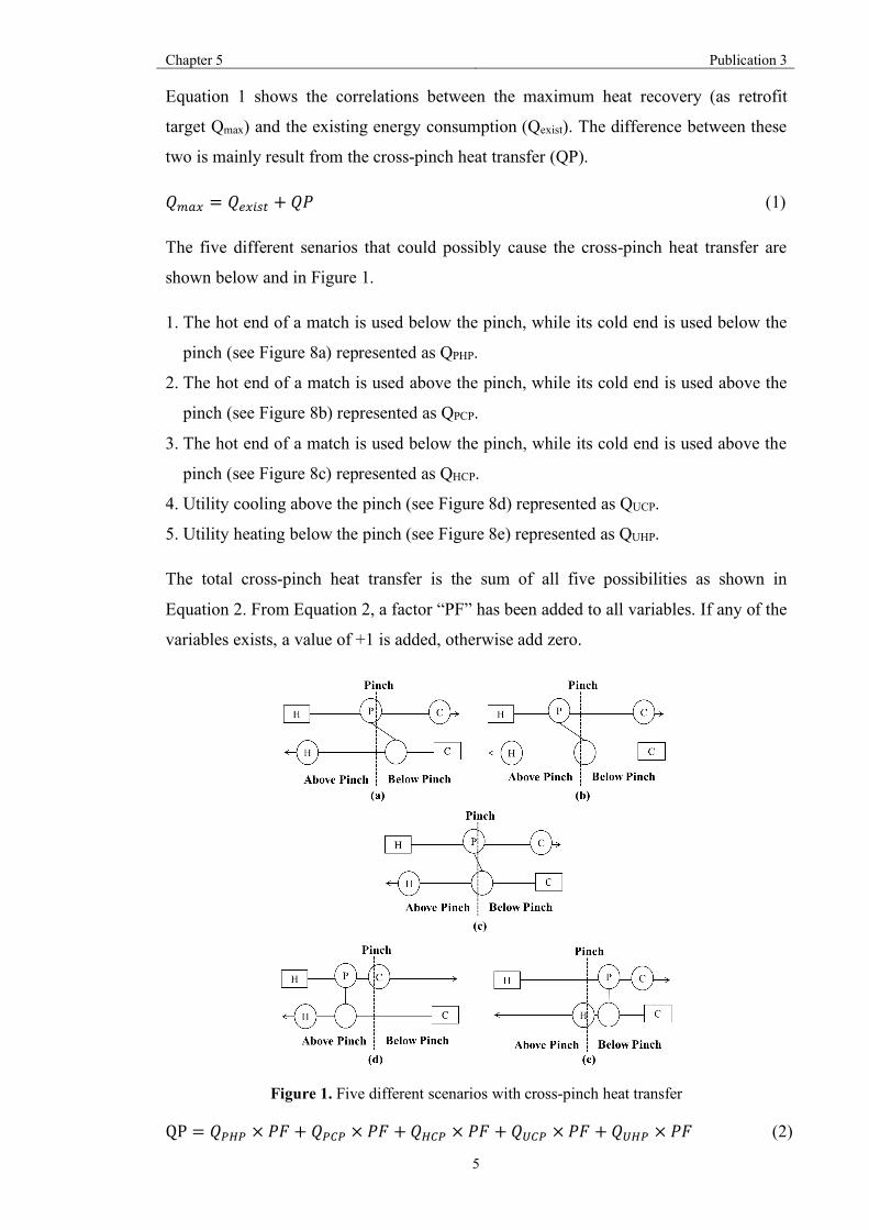
Chapter 5 Publication 3
5
Equation 1 shows the correlations between the maximum heat recovery (as retrofit
target Qmax) and the existing energy consumption (Qexist). The difference between these
two is mainly result from the cross-pinch heat transfer (QP).
𝑄nop = 𝑄~pM&° + 𝑄𝑃 (1)
The five different senarios that could possibly cause the cross-pinch heat transfer are
shown below and in Figure 1.
1. The hot end of a match is used below the pinch, while its cold end is used below the
pinch (see Figure 8a) represented as QPHP.
2. The hot end of a match is used above the pinch, while its cold end is used above the
pinch (see Figure 8b) represented as QPCP.
3. The hot end of a match is used below the pinch, while its cold end is used above the
pinch (see Figure 8c) represented as QHCP.
4. Utility cooling above the pinch (see Figure 8d) represented as QUCP.
5. Utility heating below the pinch (see Figure 8e) represented as QUHP.
The total cross-pinch heat transfer is the sum of all five possibilities as shown in
Equation 2. From Equation 2, a factor “PF” has been added to all variables. If any of the
variables exists, a value of +1 is added, otherwise add zero.
Figure 1. Five different scenarios with cross-pinch heat transfer
QP = 𝑄'º' × 𝑃𝐹 + 𝑄'F' × 𝑃𝐹 + 𝑄ºF' × 𝑃𝐹 + 𝑄xF' × 𝑃𝐹 + 𝑄xº' × 𝑃𝐹 (2)

Chapter 5 Publication 3
6
For each process-to-process and utility exchanger transferring heat across the pinch, the
cross-pinch heat transfer under each scenario given in Figure 1 can be determined using
Equation 3 to Equation 7.
𝑄'º' = 𝐶𝑃ºL𝑇'º,Mq − 𝑇º,'N (3)
𝑄'F' = 𝐶𝑃FL𝑇'D,W(° − 𝑇D,'N (4)
𝑄ºF' = 𝐶𝑃ºL𝑇'º,Mq − 𝑇º,'N − 𝐶𝑃F(𝑇'F,W(° − 𝑇F,') (5)
𝑄xF' = 𝐶𝑃ºL𝑇xº,Mq − 𝑇º,'N (6)
𝑄xº' = 𝐶𝑃F(𝑇xF,W(° − 𝑇F,') (7)
4. Retrofit Methodology
The pinch retrofit method has similar principles as the Network Pinch Approach, which
is detailed by Smith et al. [15]. The objective of pinch retrofit method is to identify the
best series of structural modifications for energy recovery with an advantage of
providing insights such as identifying the features of the existing HEN that restricts
energy recovery and the best location to apply the selected modifications to overcome
these restrictions.
The best retrofit strategy is one which meets the retrofit target with the minimum
number of structural modifications and cost. To achieve this, the modification and
technology used should be one that ensures maximum energy recovery.
The methodology proposed in this work covers the identification of the best single
modification for a given HEN based on energy recovery, the identification of the best
series of modifications i.e. multiple modifications, the use of high efficiency exchangers
in place of the conventional shell and tube heat exchanger for increased energy recovery,
and the approach used are compared with the different retrofit methods.
4.1 Single modification
Outlined below is the step-by-step approach proposed for identifying the best single
modification for a given HEN.
Step 1: pinch the network and identify features of the network restricting energy
recovery
Chapter 5 Publication 3
7
Pinching the existing HEN relative to the selected ∆Tmin identifies the HEN features
responsible for restricting energy recovery. Through pinching the existing network,
pinched exchangers and cross-pinch heat exchangers, which are caused by
inappropriate use of utilities and process-to-process heat exchangers, are identified.
By reviewing the network, the locations of these exchangers are identified through
checking the inlet and outlet temperatures of streams. By pinching the network, the
existing structure is maintained while reducing the utility consumption.
Step 2: review the identified network features and identify the best type of modification
based on energy recovery
Once the network is pinched, the best structural modification can be further
determined based on the location of the cross pinch and pinched exchangers. To
overcome the network pinch and eliminate cross pinch heat transfer, modification
options considered are resequencing, stream splitting and adding new heat
exchanger(s). Depending on the feature of the existing HEN, the best modification
can be identified as explained below.
Scenario 1: no pinched exchangers in the network
• In this situation, adding a new heat exchanger to a create utility path is beneficial.
This is because for this type of network, the main restriction to energy recovery is
the presence of cross-pinch exchangers.
• Therefore, by creating a utility path, the cross-pinch heat transfer can be
effectively decreased or eliminated, and energy consumption can be significantly
reduced.
Scenario 2: process heat exchangers located upstream of pinched exchangers
• In this situation, resequencing and adding a new heat exchanger are both possible.
This is because energy recovery is restricted by the downstream pinched
exchanger(s). Therefore, heat load can be moved from the process heat
exchangers upstream to relieve the constraint on the pinched exchangers allowing
for energy recovery.
• If moving the entire heat from the upstream heat exchanger does not violate the
temperature driving force, resequencing is recommended. When there are more
than one upstream process heat exchangers, the one with highest temperature
driving force should be selected to relocate. It should be noted that in the event of

Chapter 5 Publication 3
8
more than one exchanger having the same temperature driving force, the one with
higher heat duty is selected.
• Adding a new heat exchanger is the most beneficial choice only when moving all
load from the upstream heat exchanger across pinch violates the minimum
temperature approach constraints. With this option, a new heat exchanger can be
added downstream, allowing for some of the heat load to be moved thereby,
reducing energy consumption.
Scenario 3: No process heat exchangers located upstream of pinched exchangers
• In this scenario, adding a new heat exchanger and stream splitting are considered
as the best modifications.
• Only when there are more than two pinched heat exchangers adjacent to each
other, is introducing stream splitting beneficial. This is because the lower
temperature of cold stream and the higher temperature of hot stream ease the
driving force constraint of pinched heat exchangers.
• Otherwise, adding a new heat exchanger is recommended.
4.2 Multiple modifications
After the best single modification is applied, further modifications steps need to be
identified as shown in Figure 2a. However, Figure 2b shows that by repeating the best
single modification, the moat benefit retrofit solution might not be attained. As such, the
best retrofit strategy is one which can identify the best series of modifications that
ensures the retrofit target is met with minimum modification steps and minimum capital
cost.
Figure 2. Paths for multiple modifications
In this work, the step-by-step algorithm shown in Figure 3 is proposed. The retrofit
methodology is repeated, and the network data is updated until the retrofit energy target
is met. The best modification at each stage is obtained based on the updated network

Chapter 5 Publication 3
9
data and the key features of the new network. Note that the stopping criteria can be
different based on the user requirements. The stopping criterion used in this study is
achieving the maximum energy recovery under a certain minimum approach
temperature for a given HENs.
Figure 3. Step-by-step algorithm for multi-modification
4.3 Integration of plate heat exchanger into HEN retrofit
Plate heat exchangers, as one of most-efficient heat transfer equipment, allow for lower
minimum approach temperature (say 5 °C) compared with conventional heat
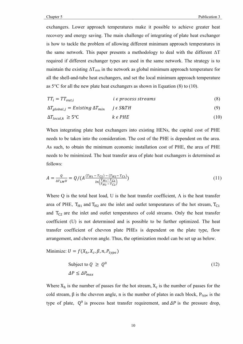
Chapter 5 Publication 3
10
exchangers. Lower approach temperatures make it possible to achieve greater heat
recovery and energy saving. The main challenge of integrating of plate heat exchanger
is how to tackle the problem of allowing different minimum approach temperatures in
the same network. This paper presents a methodology to deal with the different ΔT
required if different exchanger types are used in the same network. The strategy is to
maintain the existing ΔTmin in the network as global minimum approach temperature for
all the shell-and-tube heat exchangers, and set the local minimum approach temperature
as 5°C for all the new plate heat exchangers as shown in Equation (8) to (10).
𝑇𝑇M = 𝑇𝑇W(°,M𝑖𝜖𝑝𝑟𝑜𝑐𝑒𝑠𝑠𝑠𝑡𝑟𝑒𝑎𝑚𝑠 (8)
∆𝑇)¼W£o¼," = 𝐸𝑥𝑖𝑠𝑡𝑖𝑛𝑔∆𝑇nMq𝑗𝜖𝑆&𝑇𝐻 (9)
∆𝑇¼WDo¼,* ≥ 5℃𝑘𝜖𝑃𝐻𝐸 (10)
When integrating plate heat exchangers into existing HENs, the capital cost of PHE
needs to be taken into the consideration. The cost of the PHE is dependent on the area.
As such, to obtain the minimum economic installation cost of PHE, the area of PHE
needs to be minimized. The heat transfer area of plate heat exchangers is determined as
follows:
𝐴 = j∆0¡¢x
= 𝑄/(𝐴 (0»120�3)2(0»320�1)
¼q,8»1½8�38»3½8�3
-)(11)
Where Q is the total heat load, U is the heat transfer coefficient, A is the heat transfer
area of PHE, T¾< and T¾= are the inlet and outlet temperatures of the hot stream, TÄ<
and TÄ= are the inlet and outlet temperatures of cold streams. Only the heat transfer
coefficient (U) is not determined and is possible to be further optimized. The heat
transfer coefficient of chevron plate PHEs is dependent on the plate type, flow
arrangement, and chevron angle. Thus, the optimization model can be set up as below.
Minimize:𝑈 = 𝑓(𝑋C,𝑋D, 𝛽, 𝑛, 𝑃°.�~)
Subject to 𝑄 ≥ 𝑄K (12)
𝛥𝑃 ≤ 𝛥𝑃nop
Where Xë is the number of passes for the hot stream, XÌis the number of passes for the
cold stream, β is the chevron angle, n is the number of plates in each block, Ptype is the
type of plate, QK is process heat transfer requirement, and 𝛥𝑃 is the pressure drop,

Chapter 5 Publication 3
11
ΔPÏÙ� is the maximum pressure drop allowance. An mixed-integer non-linear
programming (MINLP) model is set up in GAMs, which is detailed by Xu et al.[16].
Under some circumstances, even when using plate heat exchangers, the approach
temperature of that heat exchanger could be much greater than the minimum allowed
owing to the restrictions created by the network structure.
With the use of PHE, the objective of the optimization model is to achieve the
maximum heat recovery at the existing minimum approach temperature with minimum
modification steps and capital costs. The stopping criterion is to meet the minimum
energy consumption at specified minimum approach temperature. This is because
although adding plate heat exchanger potentially can save more energy due to its
relative high heat transfer coefficient, to further quantify the economic benefit of
applying PHE, the maximum heat recovery at the existing minimum approach
temperature is used. Because adding a new heat exchanger into a heat exchanger
network might lead to an excess over the maximum heat recovery, a constraint for heat
recovery is required. Equation 13 shows the boundary of hot and cold utility in order to
obtain the maximum heat recovery, where Q¾is the hot utility consumption, Q¾ÏË5 is
the minimum hot utility consumption at the existing minimum approach temperature,
QÄis the cold utility consumption, QÄÏË5 is the minimum cold utility consumption at
the existing minimum approach temperature.
𝑄º ≥ 𝑄ºnMq𝑜𝑟𝑄F ≥ 𝑄FnMq(13)
4.4 Compare with different retrofit technologies
To quantify the potential benefit of integrating PHEs into retrofit design of HENs, the
retrofit results with application of shell-and-tube heat exchangers to achieve the same
amount energy saving are calculated. The utility cost and retrofit cost data are shown in
Table 1. The total retrofit cost and utility cost, payback is calculated as shown in
Equation (14) to (16).
𝑇𝑅𝐶 = 𝐻𝑋q~¬ + 𝐵𝑃 + 𝐴𝐴 (14)
𝑈𝐶 = 𝐻𝑈 + 𝐶𝑈 (15)
𝜀 = 0�FxF
(16)
Where TRC represents the total retrofit cost, BP is the cost of implementing by-pass,
AA is the cost of adding area,
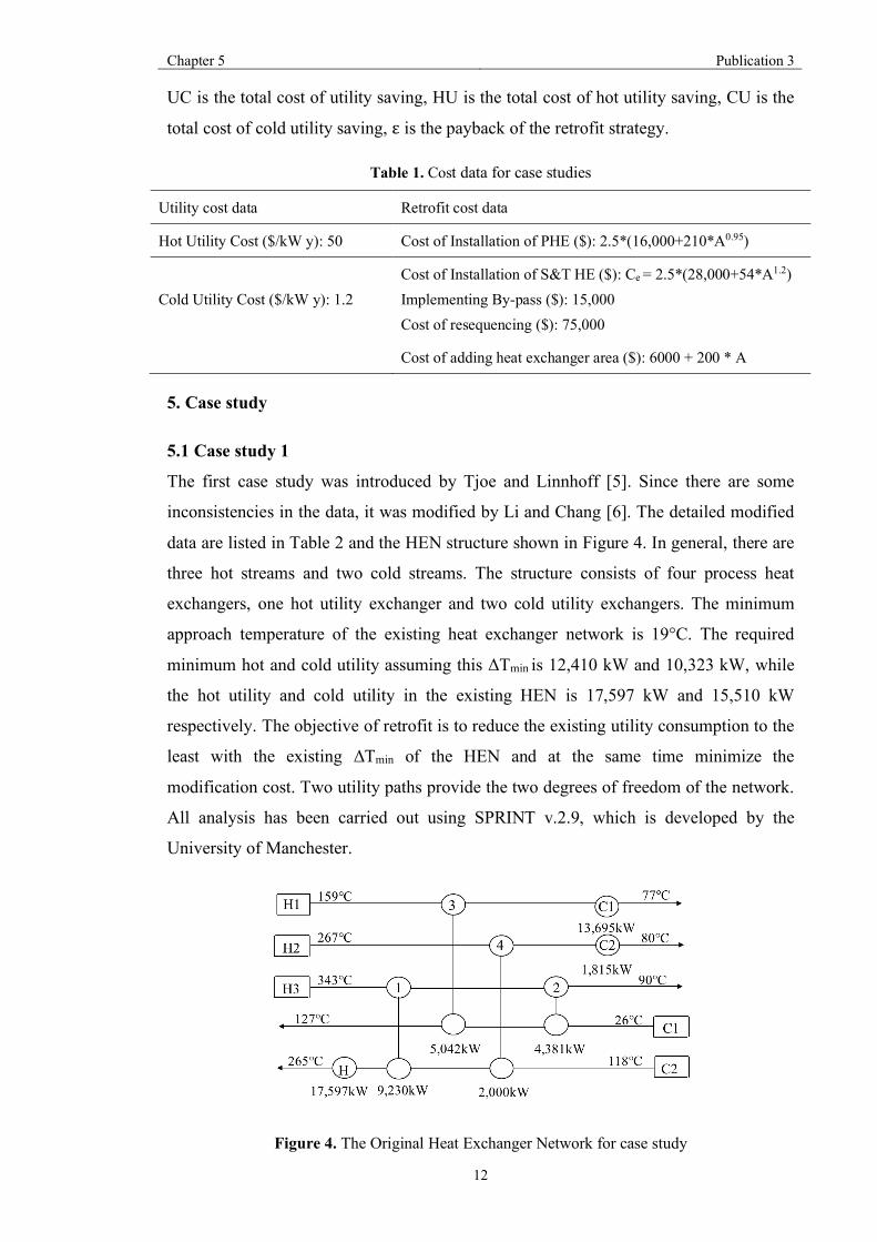
Chapter 5 Publication 3
12
UC is the total cost of utility saving, HU is the total cost of hot utility saving, CU is the
total cost of cold utility saving, ε is the payback of the retrofit strategy.
Table 1. Cost data for case studies
Utility cost data Retrofit cost data
Hot Utility Cost ($/kW y): 50 Cost of Installation of PHE ($): 2.5*(16,000+210*A0.95)
Cold Utility Cost ($/kW y): 1.2 Cost of Installation of S&T HE ($): Ce = 2.5*(28,000+54*A1.2) Implementing By-pass ($): 15,000 Cost of resequencing ($): 75,000
Cost of adding heat exchanger area ($): 6000 + 200 * A
5. Case study
5.1 Case study 1
The first case study was introduced by Tjoe and Linnhoff [5]. Since there are some
inconsistencies in the data, it was modified by Li and Chang [6]. The detailed modified
data are listed in Table 2 and the HEN structure shown in Figure 4. In general, there are
three hot streams and two cold streams. The structure consists of four process heat
exchangers, one hot utility exchanger and two cold utility exchangers. The minimum
approach temperature of the existing heat exchanger network is 19°C. The required
minimum hot and cold utility assuming this ΔTmin is 12,410 kW and 10,323 kW, while
the hot utility and cold utility in the existing HEN is 17,597 kW and 15,510 kW
respectively. The objective of retrofit is to reduce the existing utility consumption to the
least with the existing ΔTmin of the HEN and at the same time minimize the
modification cost. Two utility paths provide the two degrees of freedom of the network.
All analysis has been carried out using SPRINT v.2.9, which is developed by the
University of Manchester.
Figure 4. The Original Heat Exchanger Network for case study

Chapter 5 Publication 3
13
Table 2. Stream data of case study 1
Stream Name TS
(°C)
TT
(°C)
Q (kW) CP
(kW/°C)
H.T.C.(kW/m2°C)
H1 159 77 18,737.0 228.5 0.40
H2 267 80 3,841.8 20.4 0.30
H3 343 90 13,611.4 53.8 0.25
C1 26 127 9,423.3 93.3 0.15
C2 118 265 28,826.7 196.1 0.50
Best Single Modification Result
Heat exchangers 1 and 4 are identified as both cross process pinch exchangers and
pinched exchangers, as shown in Figure 5. Based on structure analysis, there are two
pinched exchangers and they are not adjacent. The best single modification with the
largest amount of energy saving and lowest cost is adding a new plate heat exchanger to
create a utility path. The pinch temperature for the hot and cold streams are 159°C and
140°C.
Figure 5. Pinched heat exchanger for case study 1
Applying the retrofit methodology, the pinched heat exchangers are located on the
stream with hot utility. However, no heat exchanger is located on the stream with cold
utility. No heat exchangers are located upstream from the pinched exchangers.
Therefore, resequencing and adding a new heat exchanger to create a loop are not
recommended. The energy saving is limited by applying stream splitting since there are
only two pinched exchangers in the HEN. The best location to add the new heat

Chapter 5 Publication 3
14
exchanger to form the utility path should be the streams with highest utility
consumption.
First, Figure 6 shows that the new plate heat exchanger N is added on the upstream of
Exchanger 3 on the hot stream as Exchanger 3 transfers heat across the pinch, and
upstream of the pinched exchangers on the cold stream to create a path.
Figure 6. Add new plate heat exchanger for case study 1
To quantify the potential benefit of adding a PHE, a shell-and-tube heat exchanger is
added by following the same algorithm to compare with the plate heat exchanger. The
result of adding shell-and-tube heat exchanger as a retrofit option is shown in Figure 7.
Figure 7. Add new shell-and-tube heat exchanger for case study 1
Compared with the results shown in Figure 6, location of adding the new shell-and-tube
heat exchanger and the heat load of the exchanger are the same as that for the new PHE
as shown in Figure 7. This is mainly due to the restriction of the existing network
structure. Economic cost is another factor that needs to be considered. By employing the
equations shown in Table 1, the installation cost of adding a PHE is $66,296, which is
$133,072 less than the installation cost of adding shell-and-tube heat exchanger. Thus,
adding plate heat exchanger is preferred.

Chapter 5 Publication 3
15
An alternative option for structure modification is to apply stream splitting, the result of
which is shown in Figure 8. Compared with adding a new plate heat exchanger, the
energy saving for stream splitting is 5.9% lower. Accordingly, adding a new plate heat
exchanger to create a path is the most beneficial retrofit option for the single
modification.
Figure 8. Apply stream splitting for case study 1
Best Retrofit Solution (Multiple Modifications)
By pinching the network after the first modification, heat exchangers 1, 3 and 4 are
identified as pinched exchangers, and heat exchangers 2 and 4 are identified as cross
pinch exchangers. The retrofit methodology is applied until the retrofit target is met. In
terms of the application of the methodology, although there are three pinched heat
exchangers in total, they are not adjacent to each other in the network. In this situation,
stream splitting is not a reasonable option. Since the pinched heat exchangers are on the
streams with the utility that has the highest duty, adding a new plate heat exchanger to
create a path is not the most energy effective option as the amount of energy that can be
recovered will be restricted by the pinched exchangers on the streams. For resequencing,
heat exchanger 2 is located downstream from the pinched heat exchanger 1. Therefore,
exchanger 2 cannot be moved to relieve the constraint on exchanger 1.
Figure 9 shows the best retrofit solution when a PHE is used for the new heat exchanger
required for retrofit. As shown in Figure 9, heat exchanger N2 is added next to heat
exchanger 2 in order to create a loop. The input process stream data of the heat
exchanger and the maximum heat transfer coefficient from the single optimized MINLP
model for plate heat exchanger N2 is then derived [16]. The detailed optimization model
for single PHE is proposed by Xu et al.[16]. After rebalancing the network using a

Chapter 5 Publication 3
16
nonlinear optimization algorithm, the minimum utility consumption is achieved through
adding two plate heat exchangers, which allow the ΔTmin of the PHEs to be as low as
5°C and the ΔTmin of other heat exchangers in the existing network is maintained (19°C).
Figure 9. Best retrofit solution by applying PHE for Case Study 1
To quantify the economic benefit of applying PHEs in retrofit, Figure 10 shows the best
retrofit solution by following the same proposed methodology with conventional shell
and tube heat exchanger technology instead of PHE. To achieve same amount of energy
saving, conventional technologies need three steps of structure modifications (Add 2
shell and tube heat exchangers and add 1 stream split).
Figure 10. Best retrofit solution by applying S&T HE for Case Study 1
It can be clearly seen from Figures 9 and 10 that the location of adding the two different
types of new heat exchanger are the same. This is because same algorithm is applied to
select the best modification step and technologies. However, only two structural
modifications are required with the use of PHEs compared to three when shell and tube
exchangers are used. Table 3 compares the detailed economic costs of two different
retrofit methodologies.
As shown in Table 3, some additional area and by-passes are added to exchangers
because of constraints in the network structure. The installation cost of plate heat

Chapter 5 Publication 3
17
exchanger is 31% of the installation cost of shell and tube heat exchanger. This is
because the higher heat transfer coefficient of plate heat exchanger leads to less area
requirement. The payback time of the new retrofit method (with PHE) is 1.88yr.
However, to achieve the same energy saving the payback time of the traditional retrofit
method (with shell and tube exchanger) is 5.39yr. Table 3. The comparison of two different methodologies
New retrofit method Traditional retrofit method
Modification Add 2 PHE Add 2 S&T HE and 1 stream splitting
Installation cost of adding new HX ($) 310,130 996,715
Adding area ($) 124,200 (E1,4,5,6,7) 416,920 (E1,3,4,5,7)
Cost of stream splitting ($) 75,000 45,000
Total retrofit cost ($) 509,330 1458,635
Total utility saving ($) 270,573 270,573
Payback (yr) 1.88 5.39
5.2 Case Study 2
Figure 11. The original structure of HEN for Case Study 2
A simplified crude oil pre-heat train was studied by Akpomiemie and Smith [17] and
the detailed heat exchanger network structure is shown in Figure 11. Table 4 lists the
stream properties for case study 2. In total there are 5 hot streams and 1 cold stream and
7 process heat exchangers and 5 utility heat exchangers. Six utility passes and three
loops give nine degrees of freedom. The minimum approach temperature is 10°C and
the corresponding minimum hot and cold utilities consumptions are 10,958 kW and 0
kW respectively. However, in the existing heat exchanger network, the hot and cold

Chapter 5 Publication 3
18
utilities consumptions are 14455 kW and 657 kW. The objective is to apply the
proposed retrofit approach to achieve the maximum heat recovery at the existing ΔTmin.
Table 4. The process data of Case Study 2
Stream
Name TS (°C) TT (°C) Q (kW) CP (kW/°C)
H.T.C.(kW/m2°C)
H1 310 95 18,490.0 86.0 0.5
H2 299 120 3,830.6 21.4 0.5
H3 273 250 4,248.1 184.7 0.5
H4 230 95 3,172.5 23.5 0.5
H5 206 178 3,623.2 129.4 0.5
C1 52 360 4,4321.2 143.9 0.5
After pinching the HEN (see Figure 12), the heat duty of cold utilities C1, C3 are
decreased to 0kW. Thus, the total number of utility paths decreases to four. There are
two utility pinch temperatures. These are 62°C (hot) and 52°C (cold), and 40°C (hot)
and 30°C (cold). The pinched exchangers identified are Exchangers 2, 4 and 6. There
were no cross process pinch exchangers, but exchangers C2 and C4 were identified as
cross utility pinch exchangers.
Figure 12. The pinched HEN for Case Study 2
Best Single Modification Result
Based on the proposed retrofit methodology, the most beneficial options for retrofit will
be resequencing or adding a new plate heat exchanger to create a loop. This is as a result

Chapter 5 Publication 3
19
of the presence of heat exchangers 3 and 7 upstream from the pinched exchangers. Next,
the network is analysed to determine the feasibility of moving the entire heat load of the
heat exchanger with the highest ΔTLM further downstream. The heat exchanger with the
highest ΔTLM was identified to be Exchanger 7.
Moving Exchanger 7 downstream does not violate the network temperature constraint,
as the inlet temperatures of the pinched exchangers on the cold stream C1 decreases,
which in return allows for them to take up more heat load. Therefore, the best single
modification for this case study was to resequencing Exchanger 7. Exchanger 7 is then
moved to the outlet of the pinched exchanger furthest downstream and still on a viable
utility path i.e. Exchanger 4. Figure 13 shows the network for the best single
modification.
Figure 13. The best modification for first step retrofit of HEN
Best Retrofit Solution (Multiple Modifications)
After pinching the network again, Exchangers 2, 4 and 6 are identified as pinched heat
exchangers and utility exchangers C2 and C4 transfer heat across the pinch. From
Figure 13, it can be noted that Exchanger 3 is located upstream from pinched
exchangers. As such, both resequencing and adding a new plate heat exchanger to create
a loop are the most beneficial options.
Next the feasibility of moving all the heat load of Exchanger 3 is examined. By doing
this, the network constraint is violated when Exchanger 3 is moved to the outlet of the
pinched exchanger furthest downstream. Therefore, the most beneficial option is to add
a new plate heat exchanger to create a loop with exchanger 3.

Chapter 5 Publication 3
20
After adding a new plate heat exchanger N, the maximum heat recovery at the existing
ΔTmin (10°C) is achieved as shown in Figure 14. The maximum heat transfer coefficient
of plate heat exchanger N is derived based on the input stream data from the single
optimized MINLP model.
Figure 14. The best retrofit solution for Case Study 2
To quantify the potential benefit of applying plate heat exchangers, by following the
retrofit methodology the best retrofit solution with conventional heat exchangers is
shown in Figure 15. To achieve the same amount of energy saving, the alternative
solution can also be achieved by two-step modifications. The detailed results of the two
different approaches are listed in Table 5.
Figure 15. The best retrofit solution for Case Study 2 by adding S&THX
These two approaches provide the same number of modifications, but the heat load
distribution is different. The heat load of the new plate heat exchanger is 1068kW,
higher than the traditional shell and tube heat exchanger, which benefits the downstream
Chapter 5 Publication 3
21
Exchanger 3 allowing it to release heat. The heat transfer of the new plate heat
exchanger N is limited due to its presence in the utility path H-1-2-N-3-C1 with the heat
load of heat exchanger C1 already reduced to 0. Even with more heat load on the new
heat exchanger, the installation cost of adding a plate heat exchanger is $310,130. The
total retrofit cost of new proposed methodology is $449,330, which is $1,084,305 lower
than the traditional retrofit cost to achieve the same amount of energy saving. The
payback of the traditional retrofit cost is 8.56yr, and the payback of the new proposed
method is 2.51yr.
Table 5. The comparison result of two different technologies
New retrofit method Traditional retrofit method
Modification Add 1 PHE and 1
resequence Add 1 S&T HE and 1
resequence
Capital cost of adding new HX ($) 310,130 996,715
Adding area ($) 124,200 (E1,4,5,6,7) 416,920 (E1,3,4,5,7)
Cost of stream splitting ($) 75,000 45,000
Cost of resequencing 75,000 75,000
Total retrofit cost ($) 449,330 1,533,635
Total utility saving ($) 178,996 178,996
Payback (yr) 2.51 8.56
5.3 Case study 3
A more complex case [17] is studied to further illustrate the methodologies of
retrofitting the HENs. The structure of the heat exchanger network is shown in Figure
16. In this case, there are 5 hot streams and 5 cold streams. The physical properties of
the process streams are listed in Table 6. As shown in Figure 16, there are 5 process
heat exchangers and 3 hot utilities and 4 cold utilities. Three utility paths and two loops
give the heat exchanger network five degrees of freedom. The minimum approach
temperature of the existing heat exchanger network is 12°C, and the hot and cold utility
consumptions are 28,168kW and 35,143kW respectively.

Chapter 5 Publication 3
22
Figure 16. The original structure of HEN
Table 6. Stream data of case study 3
Stream Name
TS (°C) TT (°C) Q (kW) CP
(kW/°C)
H.T.C.
(kW/m2°C)
H1 330 210 36,000 300 0.5
H2 450 220 34,500 150 0.5
H3 300 135 24,750 150 0.5
H4 380 190 38,000 200 0.5
H5 340 75 33,125 125 0.5
C1 240 430 39,900 210 0.5
C2 55 150 32,300 340 0.5
C3 70 210 30,800 220 0.5
C4 150 365 25,800 120 0.5
C5 200 370 30,600 180 0.5
By pinching the network (see Figure 17), the minimum hot and cold utility
consumptions obtained are 8,300kW and 15,275kW at the existing ∆Tmin. Exchangers 3
and 4 were identified as pinched exchangers after pinching the network. The pinch
temperatures for hot streams and cold streams are 330°C and 320°C respectively.
Exchangers 1, 2 and 3 were identified as cross process pinch exchangers, and
Exchanger H2 was identified as utility pinch exchanger.

Chapter 5 Publication 3
23
Figure 17. The pinched HEN for Case Study 3
Best Single Modification Result
To identify the best single modification, the retrofit methodology is applied. By
reviewing the pinched network, it is not possible to add a new plate heat exchanger to
create a loop or resequence since there are no process heat exchangers upstream from
the pinched exchangers. The two pinched exchangers are not adjacent, which makes the
implementation of stream splitting an infeasible solution.
Figure 18 shows the best single modification for retrofit of the existing HEN. The new
PHE is located on the utility path to connect the utility exchangers with highest duty
(C1 and H2). Also, the new exchanger has been added after the pinched exchanger 4
and it does not transfer heat across the pinch as indicated in the guidelines. It has also
been added after Exchanger 5 on stream C3 because Exchanger 5 is not on a utility path
or loop. This ensures that the network energy balance is maintained. The heat transfer
coefficient for the single plate heat exchanger is derived from the single optimized
MINLP model in GAMS after input the process stream data. The new plate heat
exchanger N allows the minimum approach temperature to be as low as 5°C.

Chapter 5 Publication 3
24
Figure 18. The first-step modification for retrofit HEN by adding new plate heat exchanger
To quantify the potential benefit, the retrofit guidelines are applied with the addition of
a shell and tube heat exchanger as shown in Figure 19. The heat transfer is limited due
to the restriction of the existing network structure. Under this circumstance, whether it
is necessary to install plate heat exchanger needs to be tested (economic cost).
Figure 19. The first-step modification for retrofit HEN by adding new shell-and tube heat
exchanger
By employing the equations in Table 1, the installation cost of adding PHE ($33,472) is
three times lower than the installation cost of adding shell and tube heat exchanger
($92,142).
Best Retrofit Solution (Multiple Modifications)
The retrofit stopping criteria is to achieve the minimum utility consumption at the
existing ΔTmin of 12°C. Pinching the network again, Exchangers 1, 2 and 3 are

Chapter 5 Publication 3
25
identified as cross process pinch exchangers. Based on the proposed methodology, the
best second modification is to add a new plate heat exchanger to create a loop with the
cross process pinch exchanger having the highest cross-pinch heat transfer (Exchanger
1). This is because there are no upstream heat exchangers from the pinched exchangers
and the pinched exchangers are not adjacent to each other, which make resequencing an
infeasible solution. Also, since the pinched exchanger is located on the streams with the
most viable utilities (H3 and C4), adding a new plate heat exchanger to create a path is
not a feasible solution, as the temperature constraint of that heat exchanger will be
violated.
Based on these reasons, adding a new plate heat exchanger to create a loop is the best
second modification. As shown in Figure 20, Exchanger N2 is added to connect utility
exchangers H3 and C4 since only the cold utility C4 is not connected to a pinched
exchanger. The same amount of energy saving, is achieved by adding the second new
shell and tube heat exchanger.
Figure 20. The best second modification for retrofit HEN
After the second modification, the maximum heat recovery is not achieved. Therefore,
the retrofit methodology is repeated until this is obtained. The final retrofit solution is
shown in Figure 21. To achieve the minimum utilities consumption at the existing ΔTmin,
7 new plate heat exchangers are added in total.

Chapter 5 Publication 3
26
Figure 21. Best retrofit solution for Case study 3 with application of plate heat exchangers
An alternative option for HEN retrofit with conventional heat exchangers to achieve the
same heat recovery is obtained by following the proposed methodology. As shown in
Figure 22, the best retrofit result requires 9 modifications and 9 new traditional
exchangers are added to create a loop or utility path. The comparisons of two different
retrofit options are listed in Table 7.
Figure 22. Best retrofit solution for Case study 3 with application of conventional heat exchangers
The difference between retrofit solutions of adding new plate heat exchangers and
adding new shell-and-tube heat exchangers results in differences that are highlighted as
follows:
1. In total, 7 new plate heat exchangers are added to achieve the maximum heat recovery
at the existing ΔTmin. Two more heat exchangers are needed when using shell and tube
heat exchangers to obtain the same amount of energy saving. This is because plate heat
exchangers allow lower minimum approach temperature. Based on the retrofit result,
the ΔTmin of new heat exchangers N3, N4 and N6 are 5°C.

Chapter 5 Publication 3
27
2. As it can be clearly seen from Figures 21 and 22, the new heat exchangers N1, N2, N3,
N4, N5 are added in the same location but with different heat loads. Since after adding
new plate heat exchanger N4, the heat load of cold utility C3 is already reduced to 0.
There is no need to add additional new heat exchangers, as shown in Figure 21.
3. The total installation cost of adding new plate heat exchangers is 18% of the total
installation cost of adding shell and tube heat exchangers. Adding on the cost of extra
area and installation of by-passes, the total retrofit cost of the new retrofit method is 41%
of the total retrofit cost of traditional retrofit method.
Table 7. The comparison result of two different technologies
New retrofit method Traditional retrofit method
Modification Add 7 PHE Add 9 S&T HE
Capital cost of adding new HX ($) 1,257,712 7,211,425
Adding area ($) 1,873,100 (E1,2,3,4,5,6,7,10) 377,126 (E1,2,5,6,7,10)
Cost of stream by-pass ($) 60,000 90,000
Cost of resequencing 0 0
Total retrofit cost ($) 3,190,812 7,678,551
Total utility saving ($) 1,017,241 1,017,241 Payback (yr) 3.14 7.55
6. Conclusion
A novel step-by-step methodology of HEN retrofit is proposed through integration of
plate heat exchanger into conventional heat exchanger networks with structure
modifications. The proposed method provides insight into how to identify the best types
of modification and location by applying pinch analysis based on the existing network
structure. A multi-step retrofit methodology towards the maximum heat recovery at the
existing minimum approach temperature is developed.
The best HEN retrofit should not only achieve the energy target in the fewest number of
modification steps and lowest retrofit cost. A methodology of dealing with two different
minimum approach temperatures within a HEN is presented. Three case studies are used
to provide insight into the potential benefit of the proposed step-by-step retrofit
methodology. The results show that to achieve the same amount of energy saving, the
utilization of plate heat exchangers can significantly reduce total retrofit cost compared
with using shell and tube heat exchangers. In some circumstances, the energy saving of
applying plate heat exchangers at each stage is limited due to the structural restrictions.

Chapter 5 Publication 3
28
However, the utilization of plate heat exchangers is always beneficial due to its low
capital cost. The proposed methodology can be applied into various HEN objectives and
stopping criteria.

Chapter 5 Publication 3
29
Nomenclature Abbreviation PHE plate heat exchanger
HEN heat exchanger network
LP linear programming
NLP non-linear programming
MILP mixed integer linear programming
MINLP mixed integer nonlinear programming
STHE shell and tube heat exchanger
Symbols
𝑄𝑚𝑎𝑥 maximum heat recovery
𝑄𝑒𝑥𝑖𝑠𝑡 existing energy consumption
𝑄𝑃 cross-pinch heat transfer
ΔTmin minimum temperature approach
CP heat capacity flowrate
𝑄º hot utility consumption
𝑄ºnMq minimum hot utility consumption
𝑄F cold utility consumption
𝑄FnMq minimum cold utility consumption
TTout,i target temperature of process stream i
ΔTlocal,k local minimum approach temperature for PHE
ΔTglobal,j global minimum approach temperature for STHE
HU hot utility
CU cold utility
∆TLM logarithmic mean temperature difference
TRC total retrofit cost
BP cost of implementing by-pass
AA cost of adding area
UC total cost of utility saving
Q total heat load
𝑋C number of passes for the hot stream
𝑋D number of passes for the cold stream
n the number of plates in each block
Ptype type of plate

Chapter 5 Publication 3
30
𝑄K process heat transfer requirement
𝛥𝑃 pressure drop
𝛥𝑃nop maximum pressure drop allowance
A heat transfer area of PHE
U heat transfer coefficient
Greek symbol
𝜀 payback time
𝛽 chevron angle
7. Reference
[1] Ochoa-Estopier LM, Jobson M, Chen L. Area-based optimization approach for
refinery heat exchanger networks. Applied Thermal Engineering. 2018;129:606-17.
[2] Pan M, Bulatov I, Smith R. Improving heat recovery in retrofitting heat exchanger
networks with heat transfer intensification, pressure drop constraint and fouling
mitigation. Applied energy. 2016;161:611-26.
[3] Smith R, Akpomiemie MO. Low Cost Retrofit Methods for Heat Exchanger
Networks. Computer Aided Chemical Engineering: Elsevier; 2017. p. 1789-94.
[4] Sundén B, Manglik RM. Plate heat exchangers: design, applications and
performance: Wit Press, 2007.
[5] Tjoe TN, Linnhoff B. Using pinch technology for process retrofit. 1986.
[6] Li B-H, Chang C-T. Retrofitting heat exchanger networks based on simple pinch
analysis. Industrial & engineering chemistry research. 2010;49(8):3967-71.
[7] Ciric AR, Floudas CA. A comprehensive optimization model of the heat exchanger
network retrofit problem. Heat Recovery Systems and CHP. 1990;10(4):407-22.
[8] Gorji-Bandpy M, Yahyazadeh-Jelodar H, Khalili M. Optimization of heat exchanger
network. Applied Thermal Engineering. 2011;31(5):779-84.
[9] Lewin DR. A generalized method for HEN synthesis using stochastic
optimization—II.: The synthesis of cost-optimal networks. Computers & chemical
engineering. 1998;22(10):1387-405.
[10] Dipama J, Teyssedou A, Sorin M. Synthesis of heat exchanger networks using
genetic algorithms. Applied Thermal Engineering. 2008;28(14-15):1763-73.
[11] Yee TF, Grossmann IE. Optimization model for structural modifications in the
retrofit of heat exchanger networks. 1986.

Chapter 5 Publication 3
31
[12] Yee TF, Grossmann IE. A screening and optimization approach for the retrofit of
heat-exchanger networks. Industrial & engineering chemistry research. 1991;30(1):146-
62.
[13] Ma K-L, Hui C-W, Yee TF. Constant approach temperature model for HEN retrofit.
Applied Thermal Engineering. 2000;20(15-16):1505-33.
[14] Asante N, Zhu X. An automated approach for heat exchanger network retrofit
featuring minimal topology modifications. Computers & chemical engineering.
1996;20:S7-S12.
[15] Smith R, Jobson M, Chen L. Recent development in the retrofit of heat exchanger
networks. Applied Thermal Engineering. 2010;30(16):2281-9.
[16] Xu K, Smith R, Zhang N. Design and optimization of plate heat exchanger
networks. Computer Aided Chemical Engineering: Elsevier; 2017. p. 1819-24.
[17] Akpomiemie MO, Smith R. Retrofit of heat exchanger networks with heat transfer
enhancement based on an area ratio approach. Applied energy. 2016;165:22-35.

Chapter 6 Conclusion and Future work
67
Chapter 6 Conclusions and Future work
6.1 Conclusions
The aim of this research was to develop a new optimization method for a single multi-
pass heat exchanger design and integrate plate heat exchanger and shell-and-tube heat
exchangers into a heat exchanger network retrofit. The existing methodologies of HEN
retrofit and the identification of gaps from the literature review provide an insight to
how to achieve this goal. Firstly, an automated systematic approach of the design multi-
pass plate heat exchangers, which involve in gasket plate heat exchanger and welded
plate heat exchangers, has been proposed. However, lack of reliable design methods to
quantify the potential benefit of applying plate heat exchanger limits the application of
plate heat exchangers. The small minimum approach temperature of plate heat
exchangers increases the energy saving, but the installation cost of plate heat
exchangers is relatively high. Therefore, a methodology of application of plate heat
exchangers into the retrofit design of conventional heat exchanger network retrofit
considering the trade-off between capital cost and energy conservation with fixed
structure has been developed. However, the energy saving is limited with the fixed
structure. Therefore, this thesis considers the structure modification in the retrofit of
heat exchanger networks. A step-by-step retrofit methodology of integrating plate heat
exchanger into heat exchanger networks to achieve the maximum heat recovery with the
minimum retrofit cost, which allows topology changes, has been proposed. The main
contributions of this research that achieve the three objectives of the thesis are detailed
as follows.
6.1.1 Automated optimization methodology of plate heat exchangers
design
A computer-aided optimization methodology of multi-pass plate heat exchanger design,
including gasket and welded plate heat exchangers, has been proposed to obtain the
optimum exchanger configuration. A MINLP problem has been formulated considering
standardized plate sizes and the unique pressure drop and heat transfer characteristics

Chapter 6 Conclusion and Future work
68
for numbers of plate patterns and flow arrangement. The integer variables involved in
the basic plate geometries and the number of plates is determined to obtain the
minimum heat transfer area of plate heat exchangers. Through employing an
enumeration method, the flow arrangement selection is integrated into the thermal-
hydraulic model. Compared with published literature, this new proposed methodology
gives a better design solution with less computation effort.
6.1.2 Application of plate heat exchanger into retrofit with fixed
structure
Heat transfer enhancement has been used to some extent in the retrofit design of HENs
as it can significantly decrease the cost of the retrofit based on the literature survey.
However, for enhancement to be effective, at least 50% of the overall heat transfer
resistance must be either the tube-side film coefficient or the shell-side film coefficient.
Owing to the limitations of heat transfer enhancement, other types of high-efficiency
heat exchangers, such as plate heat exchangers, have been considered for HEN retrofit.
Thus, a novel methodology of application of plate heat exchanger into the retrofit
design of HENs has been proposed.
The objective is to maximize the retrofit profit, which is the profit of energy saving
minus the cost of retrofit, while meeting the constraints. A significant challenge of
integration of plate heat exchangers and conventional heat exchangers is dealing with
different minimum approach temperatures and identifying the best heat exchangers to
replace. To achieve these goals, a three-stage optimization approach has been developed.
The first stage is to identify the candidate heat exchangers and the best sequence for
replacing the plate heat exchangers. Only the exchangers on utility paths are considered
for replacement based on the principle of energy balance. The incidence matrix
approach is used for the identification of candidate heat exchangers on utility paths.
Sensitivity analysis is used to identify the best heat exchangers to replace based on the
passive response a heat exchanger has on the network. The second stage is to replace the
identified heat exchanger with plate heat exchanger. To obtain the minimum capital cost
of plate heat exchangers, the maximum heat transfer coefficient is derived from the
model proposed in the first paper based on the process stream data. The third stage is to
develop a NLP model to rebalance the network and maximize the retrofit profit after the
replacement by varying the heat duty of exchangers on the utility path and the heat
transfer coefficient of exchangers not on utility paths.

Chapter 6 Conclusion and Future work
69
The proposed method combines heuristics and optimization, which encourages user
interaction and ensures the optimal heat recovery is achieved. The results show that
compared to the heat transfer technologies, application of plate heat exchangers makes
it possible to increase the heat recovery significantly due to the small minimum
approach temperature. But the installation cost of the plate heat exchangers is relatively
high. Therefore, plate heat exchangers can be used as an alternative option for the
retrofit design of PHEs. The savings are constrained mainly due to the maintained
original sizes.
6.1.3 Application of plate heat exchanger into retrofit with topology
change
A step-by-step novel methodology of utilizing the high efficiency plate heat exchangers
into the retrofit design of PHEs, which allows for structure modification, has been
proposed. The objective of this research is to achieve the maximum heat recovery at a
certain minimum temperature difference with the minimum steps of modifications and
retrofit cost. The distinctive feature of this approach is handling the different minimum
approach temperatures for the different types of exchangers within an optimization
framework. Pinch analysis is used to provide insight into how to identify the best types
of modification and their location. For the best HEN retrofit solution, the minimum
modification steps and lowest retrofit cost is required. Thus, an algorithm to identify the
most beneficial modification methods depending on the different scenario has been
developed, which significantly saves the computation time for the optimization process.
The results show that, compared with shell and tube heat exchangers, the utilization of
plate heat exchangers is always beneficial and dramatically reduces the retrofit cost to
achieve the same amount of energy savings. The proposed methodology can be applied
into various HENs retrofit based on the users’ objectives.
6.2 Future work
Although the objectives in this thesis have been met, further research should address the
following problems.
1. The optimization of a single plate heat exchanger design considered two stream heat
transfer. However, it is possible for plate heat exchangers to handle heat transfer with
multiple streams. The proposed methodology for thermal-hydraulic model of plate
Chapter 6 Conclusion and Future work
70
heat exchanger can be further extended to the multi-stream heat transfer by dividing
the overall heat exchanger into several two-stream blocks.
2. The optimization approach of plate heat exchanger design for single phase has been
proposed with constant physical properties. However, the heat transfer process can
involve phase change. Future work can consider phase change in the optimization
model of design a plate heat exchanger.
3. The thermal-hydraulic model of a single plate heat exchanger used in this work fails
to consider flow mal-distribution. However, in practical applications, maldistribution
is not negligible, especially in the multi-pass flow arrangements, which may affect
the heat transfer behavior. Since each block has different flow types, the
maldistribution mostly happens in the channels between different blocks. It can be
assumed that there are two different temperatures in the upper and lower layer of
channel, and use the average temperature as the real temperature of the fluids in the
channel. The model can be then optimized by following the same approach proposed
in Chapter 3.
4. In this work, the fouling issue of plate heat exchangers has been neglected.
Compared with traditional shell and tube heat exchangers,plate heat exchangers are
less prone to fouling due to turbulence in the flow and high shear stress in plate heat
exchangers. It might be beneficial to consider the fouling issue when applying plate
heat exchangers in the retrofit design of HENs and quantifying the potential benefit.
5. The approach to retrofit in this work has mainly focused on the integration of a
mixture of plate and shell-and-tube heat exchangers in heat exchanger networks. The
pressure drop is a key factor that cannot be neglected. The pressure drop is
recommended in future work when dealing with two different types of heat
exchangers

References
71
References
ABU-KHADER, M. M. 2012. Plate heat exchangers: recent advances. Renewable and sustainable energy reviews, 16, 1883-1891.
AHMAD, S. & PATELA, E. 1987. Supertarget: Applications software for oil refinery retrofit. American Institute of Chemical Engineers, New York, NY.
ALFALAVAL. Compabloc [Online]. Available: http://www.alfalaval.co.uk/products/heat-transfer/plate-heat-exchangers/Welded-plate-and-block-heat-exchangers/compabloc/ [Accessed].
ALFALAVAL Gasketed plate-and-frame heat exchangers.
ALFALAVAL. 2015. Rosneft Tuapse fuels up its energy recovery [Online]. Available: http://www.alfalaval.co.uk/media/stories/crude-oil-refinery/rosneft-tuapse-fuels-up-its-energy-recovery/ [Accessed 25/05/2015].
ARSENYEVA, O., KAPUSTENKO, P., TOVAZHNYANSKYY, L. & KHAVIN, G. 2013. The influence of plate corrugations geometry on plate heat exchanger performance in specified process conditions. Energy, 57, 201-207.
ARSENYEVA, O., TOVAZHNYANSKY, L., KAPUSTENKO, P. & KHAVIN, G. 2009. Mathematical modelling and optimal design of plate-and-frame heat exchangers. Chemical Engineering Transactions, 18, 791-796.
ARSENYEVA, O. P., TOVAZHNYANSKY, L. L., KAPUSTENKO, P. O. & KHAVIN, G. L. 2011. Optimal design of plate-and-frame heat exchangers for efficient heat recovery in process industries. Energy, 36, 4588-4598.
ASANTE, N. & ZHU, X. 1996. An automated approach for heat exchanger network retrofit featuring minimal topology modifications. Computers & chemical engineering, 20, S7-S12.
ASANTE, N. & ZHU, X. 1997. An automated and interactive approach for heat exchanger network retrofit. Chemical Engineering Research and Design, 75, 349-360.
ATHIER, G., FLOQUET, P., PIBOULEAU, L. & DOMENECH, S. 1998. A mixed method for retrofiting heat-exchanger networks. Computers & chemical engineering, 22, S505-S511.
BAKHTIARI, B. & BEDARD, S. 2013. Retrofitting heat exchanger networks using a modified network pinch approach. Applied Thermal Engineering, 51, 973-979.
BARBARO, A. & BAGAJEWICZ, M. J. 2005. New rigorous one-step MILP formulation for heat exchanger network synthesis. Computers & chemical engineering, 29, 1945-1976.

References
72
BERGLES, A. 1998. Techniques to enhance heat transfer. Handbook of heat transfer, 3, 11.1-11.76.
BOCHENEK, R. & JEŻOWSKI, J. 2006. Genetic algorithms approach for retrofitting heat exchanger network with standard heat exchangers. Computer Aided Chemical Engineering. Elsevier.
BOCHENEK, R. & JEŻOWSKI, J. M. 2010. Genetic algorithms formulation for retrofitting heat exchanger network. Stochastic Global Optimization: Techniques and Applications in Chemical Engineering (With CD-ROM). World Scientific.
BORGES, J. L., QUEIROZ, E. M., PESSOA, F. L., LIPORACE, F. S., OLIVEIRA, S. G. & COSTA, A. L. 2009. Fouling Management in Crude Oil Preheat Trains Through Stream Split Optimization. Computer Aided Chemical Engineering, 27, 1587-1592.
BOSSAN, D., GRILLOT, J., THONON, B. & GRANDGEORGE, S. 1995. Experimental study of particulate fouling in an industrial plate heat exchanger. Journal of Enhanced Heat Transfer, 2.
BRIONES, V. & KOKOSSIS, A. 1996. A new approach for the optimal retrofit of heat exchanger networks. Computers & chemical engineering, 20, S43-S48.
BRIONES, V. & KOKOSSIS, A. 1999. Hypertargets: a Conceptual Programming approach for the optimization of industrial heat exchanger networks—II. Retrofit design. Chemical Engineering Science, 54, 541-561.
CARLSSON, A., FRANCK, P.-A. & BERNTSSON, T. 1993. Design better heat exchanger network retrofits. Chemical Engineering Progress;(United States), 89.
CIRIC, A. & FLOUDAS, C. 1989. A retrofit approach for heat exchanger networks. Computers & chemical engineering, 13, 703-715.
CIRIC, A. R. & FLOUDAS, C. A. 1990. A comprehensive optimization model of the heat exchanger network retrofit problem. Heat Recovery Systems and CHP, 10, 407-422.
COLETTI, F. & MACCHIETTO, S. 2011. A dynamic, distributed model of shell-and-tube heat exchangers undergoing crude oil fouling. Industrial & engineering chemistry research, 50, 4515-4533.
COOPER, A. & USHER, J. D. 1983. Plate heat exchangers, in: Heat Exchanger Design Handbook. Hemisphere Publishing Corporation.
DOLAN, W., CUMMINGS, P. & LEVAN, M. 1989. Process optimization via simulated annealing: application to network design. AIChE Journal, 35, 725-736.
FOCKE, W. 1986. Selecting optimum plate heat exchanger surface patterns. Journal of heat transfer, 108, 153-160.

References
73
GHERASIM, I., GALANIS, N. & NGUYEN, C. T. 2009. Effects of dissipation and temperature-dependent viscosity on the performance of plate heat exchangers. Applied Thermal Engineering, 29, 3132-3139.
GHERASIM, I., GALANIS, N. & NGUYEN, C. T. 2011a. Heat transfer and fluid flow in a plate heat exchanger. Part II: Assessment of laminar and two-equation turbulent models. International Journal of Thermal Sciences, 50, 1499-1511.
GHERASIM, I., TAWS, M., GALANIS, N. & NGUYEN, C. T. 2011b. Heat transfer and fluid flow in a plate heat exchanger part I. Experimental investigation. International Journal of Thermal Sciences, 50, 1492-1498.
GONçALVES, C. D. O., QUEIROZ, E. M., PESSOA, F. L., LIPORACE, F. S., OLIVEIRA, S. G. & COSTA, A. L. 2014. Heuristic optimization of the cleaning schedule of crude preheat trains. Applied Thermal Engineering, 73, 3-14.
GUNDERSEN, T. 2013. Heat integration: targets and heat exchanger network design. Handbook of Process Integration (PI). Elsevier.
GUT, J. A., FERNANDES, R., PINTO, J. M. & TADINI, C. C. 2004. Thermal model validation of plate heat exchangers with generalized configurations. Chemical Engineering Science, 59, 4591-4600.
GUT, J. A. & PINTO, J. M. 2003. Selecting optimal configurations for multisection plate heat exchangers in pasteurization processes. Industrial & engineering chemistry research, 42, 6112-6124.
GUT, J. A. & PINTO, J. M. 2004. Optimal configuration design for plate heat exchangers. International journal of heat and mass transfer, 47, 4833-4848.
HEGGS, P., SANDHAM, P., HALLAM, R. & WALTON, C. 1997. Local transfer coefficients in corrugated plate heat exchanger channels. Chemical Engineering Research and Design, 75, 641-645.
HESSELGREAVES, J. E. 2001. Compact heat exchangers: selection, design and operation, Gulf Professional Publishing.
HEWITT, G. F., SHIRES, G. L. & BOTT, T. R. 1994. Process heat transfer, CRC press Boca Raton, FL.
ISHIYAMA, E., HEINS, A., PATERSON, W., SPINELLI, L. & WILSON, D. 2010. Scheduling cleaning in a crude oil preheat train subject to fouling: Incorporating desalter control. Applied Thermal Engineering, 30, 1852-1862.
ISHIYAMA, E. M., PATERSON, W. R. & WILSON, D. I. 2009. The effect of fouling on heat transfer, pressure drop, and throughput in refinery preheat trains: optimization of cleaning schedules. Heat transfer engineering, 30, 805-814.

References
74
JEŻOWSKI, J., BOCHENEK, R. & POPLEWSKI, G. 2007. On application of stochastic optimization techniques to designing heat exchanger-and water networks. Chemical Engineering and Processing: Process Intensification, 46, 1160-1174.
KAKAC, S., LIU, H. & PRAMUANJAROENKIJ, A. 2012. Heat exchangers: selection, rating, and thermal design, CRC press.
KANARIS, A., MOUZA, A. & PARAS, S. 2009. Optimal design of a plate heat exchanger with undulated surfaces. International Journal of Thermal Sciences, 48, 1184-1195.
KANDLIKAR, S. G. & SHAH, R. K. 1989. Asymptotic effectiveness-NTU formulas for multipass plate heat exchangers. Journal of heat transfer, 111, 314-321.
KAPUSTENKO, P., BOLDYRYEV, S., ARSENYEVA, O. & KHAVIN, G. 2009. The use of plate heat exchangers to improve energy efficiency in phosphoric acid production. Journal of Cleaner Production, 17, 951-958.
KUMAR, H. The plate heat exchanger: construction and design. Institute of Chemical Engineering Symposium Series, 1984. 1275-1288.
LI, B.-H. & CHANG, C.-T. 2010. Retrofitting heat exchanger networks based on simple pinch analysis. Industrial & engineering chemistry research, 49, 3967-3971.
LIU, X.-W., LUO, X. & MA, H.-G. 2014. Studies on the retrofit of heat exchanger network based on the hybrid genetic algorithm. Applied thermal engineering, 62, 785-790.
LUAN, Z.-J., ZHANG, G.-M., TIAN, M.-C. & FAN, M.-X. 2008. Flow resistance and heat transfer characteristics of a new-type plate heat exchanger. Journal of Hydrodynamics, Ser. B, 20, 524-529.
MA, K.-L., HUI, C.-W. & YEE, T. F. 2000. Constant approach temperature model for HEN retrofit. Applied Thermal Engineering, 20, 1505-1533.
MANGLIK, R. 2003. Heat transfer enhancement. Wiley, New York.
MANGLIK, R. M. & MULEY, A. 1993. Heat Transfer and Pressure Drop Characteristics of Plate-and-Frame Heat Exchangers: A Literature Review, Thermal-Fluids Laboratory, Department of Mechanical, Industrial and Nuclear Engineering, University of Cincinnati.
MARKOWSKI, M., TRAFCZYNSKI, M. & URBANIEC, K. 2013. Identification of the influence of fouling on the heat recovery in a network of shell and tube heat exchangers. Applied energy, 102, 755-764.
MARRIOTT, J. 1977. Performance of an Alfaflex Plate Heat-Exchanger. Chemical engineering progress, 73, 73-78.

References
75
MARTIN, H. 1996. A theoretical approach to predict the performance of chevron-type plate heat exchangers. Chemical Engineering and Processing: Process Intensification, 35, 301-310.
MEHRABIAN, M. 2009. Construction, performance, and thermal design of plate heat exchangers. Proceedings of the Institution of Mechanical Engineers, Part E: Journal of Process Mechanical Engineering, 223, 123-131.
MOTA, F. A., RAVAGNANI, M. A. & CARVALHO, E. 2014. Optimal design of plate heat exchangers. Applied Thermal Engineering, 63, 33-39.
MULEY, A. & MANGLIK, R. 1999. Experimental study of turbulent flow heat transfer and pressure drop in a plate heat exchanger with chevron plates. Journal of heat transfer, 121, 110-117.
MULEY, A., MANGLIK, R. & METWALLY, H. 1999. Enhanced heat transfer characteristics of viscous liquid flows in a chevron plate heat exchanger. Journal of heat transfer, 121, 1011-1017.
MULEY, A. & MANGLIK, R. M. 1997. Enhanced heat transfer characteristics of single-phase flows in a plate heat exchanger with mixed chevron plates. Journal of Enhanced Heat Transfer, 4.
NAJAFI, H. & NAJAFI, B. 2010. Multi-objective optimization of a plate and frame heat exchanger via genetic algorithm. Heat and Mass Transfer, 46, 639-647.
NASR, M. R. J. & GIVI, M. M. 2006. Modeling of crude oil fouling in preheat exchangers of refinery distillation units. Applied Thermal Engineering, 26, 1572-1577.
NGUYEN, D. Q., BARBARO, A., VIPANURAT, N. & BAGAJEWICZ, M. J. 2010. All-at-once and step-wise detailed retrofit of heat exchanger networks using an MILP model. Industrial & engineering chemistry research, 49, 6080-6103.
NIELSEN, J. S., HANSEN, M. W. & BAY JOERGENSEN, S. 1996. Heat exchanger network modelling framework for optimal design and retrofitting. Computers & chemical engineering, 20, S249-S254.
NORDMAN, R. & BERNTSSON, T. 2001. New pinch technology based hen analysis methodologies for cost- effective retrofitting. The Canadian Journal of Chemical Engineering, 79, 655-662.
NORDMAN, R. & BERNTSSON, T. 2009. Use of advanced composite curves for assessing cost-effective HEN retrofit I: Theory and concepts. Applied Thermal Engineering, 29, 275-281.
PAN, M., BULATOV, I. & SMITH, R. 2013. New MILP-based iterative approach for retrofitting heat exchanger networks with conventional network structure modifications. Chemical Engineering Science, 104, 498-524.

References
76
PANCHAL, C. & HUANGFU, E.-P. 2000. Effects of mitigating fouling on the energy efficiency of crude-oil distillation. Heat transfer engineering, 21, 3-9.
PANDEY, S. D. & NEMA, V. 2011. An experimental investigation of exergy loss reduction in corrugated plate heat exchanger. Energy, 36, 2997-3001.
PANTZALI, M., MOUZA, A. & PARAS, S. 2009. Investigating the efficacy of nanofluids as coolants in plate heat exchangers (PHE). Chemical Engineering Science, 64, 3290-3300.
PAPOULIAS, S. A. & GROSSMANN, I. E. 1983. A structural optimization approach in process synthesis—II: Heat recovery networks. Computers & Chemical Engineering, 7, 707-721.
PETERMEIER, H., BENNING, R., DELGADO, A., KULOZIK, U., HINRICHS, J. & BECKER, T. 2002. Hybrid model of the fouling process in tubular heat exchangers for the dairy industry. Journal of Food Engineering, 55, 9-17.
PICóN-NúñEZ, M., MARTíNEZ-RODRíGUEZ, G. & LOPEZ-ROBLES, J. 2006. Alternative design approach for multipass and multi-stream plate heat exchangers for use in heat recovery systems. Heat transfer engineering, 27, 12-21.
PICÓN-NúñEZ, M., POLLEY, G. T. & JANTES-JARAMILLO, D. 2010. Alternative design approach for plate and frame heat exchangers using parameter plots. Heat transfer engineering, 31, 742-749.
PIGNOTTI, A. & SHAH, R. 1992. Effectiveness-number of transfer units relationships for heat exchanger complex flow arrangements. International journal of heat and mass transfer, 35, 1275-1291.
PINTO, J. & GUT, J. 2002. A screening method for the optimal selection of plate heat exchanger configurations. Brazilian Journal of Chemical Engineering, 19, 433-439.
PONCE-ORTEGA, J. M., JIMéNEZ-GUTIéRREZ, A. & GROSSMANN, I. E. 2008a. Optimal synthesis of heat exchanger networks involving isothermal process streams. Computers & Chemical Engineering, 32, 1918-1942.
PONCE-ORTEGA, J. M., JIMéNEZ-GUTIéRREZ, A. & GROSSMANN, I. E. 2008b. Simultaneous retrofit and heat integration of chemical processes. Industrial & engineering chemistry research, 47, 5512-5528.
QIAO, H., AUTE, V., LEE, H., SALEH, K. & RADERMACHER, R. 2013. A new model for plate heat exchangers with generalized flow configurations and phase change. international journal of refrigeration, 36, 622-632.
RAJU, K. & BANSAL, J. 1983. Design of plate heat exchangers. Low Reynolds number flow heat exchangers, 913-932.

References
77
RAO, B. P., KUMAR, P. K. & DAS, S. K. 2002. Effect of flow distribution to the channels on the thermal performance of a plate heat exchanger. Chemical Engineering and Processing: Process Intensification, 41, 49-58.
REZAEI, E. & SHAFIEI, S. 2009. Heat exchanger networks retrofit by coupling genetic algorithm with NLP and ILP methods. Computers & Chemical Engineering, 33, 1451-1459.
RODRIGUEZ, C. A. 2005. Fouling mitigation strategies for heat exchanger networks, The University of Manchester (United Kingdom).
ROHSENOW, W. M., HARTNETT, J. P. & CHO, Y. I. 1998. Handbook of heat transfer, McGraw-Hill New York.
SABOO, A., MORARI, M. & COLBERG, R. D. 1986. RESHEX: An interactive software package for the synthesis and analysis of resilient heat-exchanger networks—I: Program description and application. Computers & chemical engineering, 10, 577-589.
SAUNDERS, E. A. D. 1988. Heat exchangers.
SHAH, R. 1983. Heat exchanger basic design methods. Hemisphere Publishing Corp. Washington, DC.
SHAH, R. & FOCKE, W. 1988. Plate heat exchangers and their design theory. Heat Transfer Equipment Design, 227, 254.
SHAH, R. & MUELLER, A. 1985. Heat exchanger basic thermal design methods. Handbook of Heat Transfer Applications, 1-77.
SHAH, R. K., KRAUS, A. D. & METZGER, D. 1990. Compact heat exchangers.
SHAH, R. K. & SEKULIC, D. P. 2003. Fundamentals of heat exchanger design, John Wiley & Sons.
SHAH, R. K., SUBBARAO, E. C. & MASHELKAR, R. A. 1988. Heat transfer equipment design, CRC Press.
SHEIKHOLESLAMI, M., GORJI-BANDPY, M. & GANJI, D. D. 2015. Review of heat transfer enhancement methods: Focus on passive methods using swirl flow devices. Renewable and sustainable energy reviews, 49, 444-469.
SHENOY, U. V. 1995. Heat exchanger network synthesis: process optimization by energy and resource analysis, Gulf Professional Publishing.
SHOKOYA, C. G. 1992. Retrofit of heat exchanger networks for bebottlenecking and energy savings. University of Manchester, Institute of Science and Technology.
SMITH, R., JOBSON, M. & CHEN, L. 2010. Recent development in the retrofit of heat exchanger networks. Applied Thermal Engineering, 30, 2281-2289.

References
78
SORŠAK, A. & KRAVANJA, Z. 2004. MINLP retrofit of heat exchanger networks comprising different exchanger types. Computers & Chemical Engineering, 28, 235-251.
SREEPATHI, B. K. & RANGAIAH, G. 2014. Review of heat exchanger network retrofitting methodologies and their applications. Industrial & engineering chemistry research, 53, 11205-11220.
SUNDéN, B. & MANGLIK, R. M. 2007. Plate heat exchangers: design, applications and performance, Wit Press.
THONON, B., VIDIL, R. & MARVILLET, C. 1995. Recent research and developments in plate heat exchangers. Journal of Enhanced Heat Transfer, 2.
TJOE, T. N. & LINNHOFF, B. 1986. Using pinch technology for process retrofit.
TOVAZHNYANSKII, L., KAPUSTENKO, P., PAVLENKO, V., DEREVYANCHENKO, I., BABAK, T. & LUPYR', V. 1992. The optimum design of multi-pass dismountable plate heat exchangers. Chemical and Petroleum Engineering, 28, 354-359.
TOWNSEND, D. & LINNHOFF, B. Surface area targets for heat exchanger networks. IChemE Annual Research Meeting, Bath, UK, 1984.
TSAI, Y.-C., LIU, F.-B. & SHEN, P.-T. 2009. Investigations of the pressure drop and flow distribution in a chevron-type plate heat exchanger. International communications in heat and mass transfer, 36, 574-578.
VAN REISEN, J. L., GRIEVINK, J., POLLEY, G. T. & VERHEIJEN, P. J. 1995. The placement of two-stream and multi-stream heat-exchangers in an existing network through path analysis. Computers & chemical engineering, 19, 143-148.
VAN REISEN, J. L., POLLEY, G. T. & VERHEIJEN, P. J. 1998. Structural targeting for heat integration retrofit. Applied Thermal Engineering, 18, 283-294.
VARBANOV, A. S. & KLEMEŠ, J. 2000. Rules for paths construction for HENs debottlenecking. Applied Thermal Engineering, 20, 1409-1420.
WADEKAR, V. V. 1998. Improving Industrial Heat Transfer-Compact and Not-So-Compact Heat Exchangers. Journal of Enhanced Heat Transfer, 5.
WANG, L. & SUNDEN, B. 2003. Optimal design of plate heat exchangers with and without pressure drop specifications. Applied Thermal Engineering, 23, 295-311.
WEBB, R. L. & KIM, N.-H. 1994. Principl of enhanced heat transfer. Taylor Francis: New York, NY, USA.

References
79
WRIGHT, A. & HEGGS, P. 2002a. Rating calculation for plate heat exchanger effectiveness and pressure drop using existing performance data. Chemical Engineering Research and Design, 80, 309-312.
WRIGHT, A. & HEGGS, P. 2002b. Simplified methodology for calculating the effectiveness of a two stream plate heat exchanger with one stream undergoing a phase change. Chemical Engineering Research and Design, 80, 313-319.
YEE, T. F. & GROSSMANN, I. E. 1986. Optimization model for structural modifications in the retrofit of heat exchanger networks.
YEE, T. F. & GROSSMANN, I. E. 1991. A screening and optimization approach for the retrofit of heat-exchanger networks. Industrial & engineering chemistry research, 30, 146-162.
ZETTLER, H., WEI, M., ZHAO, Q. & MüLLER-STEINHAGEN, H. 2005. Influence of surface properties and characteristics on fouling in plate heat exchangers. Heat transfer engineering, 26, 3-17.
ZHANG, H. & RANGAIAH, G. P. 2013. One-step approach for heat exchanger network retrofitting using integrated differential evolution. Computers & chemical engineering, 50, 92-104.
ZHANG, H., RANGAIAH, G. P. & BONILLA-PETRICIOLET, A. 2011. Integrated differential evolution for global optimization and its performance for modeling vapor–liquid equilibrium data. Industrial & engineering chemistry research, 50, 10047-10061.
ZINGER, N., BARMINA, L. & TARADAI, A. 1988. Design of plate heat exchangers for heat supply systems. Thermal Engineering (English Translation of Teploenergetika), 35, 141e5

80