Embed Size (px)
Citation preview

Design and Optimization of Microwave System for
Energy Efficient Remediation of Nuclear and E-
Waste
by
Hrishikesh Mishra (ENGG01201718002)
A Thesis Submitted to the
Board of Studies in Engineering Sciences
In Partial Fulfilment of Requirements
for the Degree of
Doctor of Philosophy
of
HOMI BHABHA NATIONAL INSTITUTE
June 2021


Dedicated to my grand mother Amma & my parents Babuji - Mammi

iii
Acknowledgement
It is my great pleasure to acknowledge the constant support and encouragement of my adviser,
Prof. (Dr.) S. Banerjee. His vision and mentorship were cornerstones in this work. I also thank
my guide, Dr. A. P. Tiwari, the technical adviser, Dr. (Mrs.) Archana Sharma and other
committee members for their timely comments, suggestions and gentle persuasive nudges that
have helped directly in research work and at times, to focus on this work. It was due to them
and under their watchful eyes that I was able to improve and hone this research problem. I am
grateful to Dr. Sekhar Basu, who encouraged me and provided the first impetus to take up the
research work, with all valuable inputs.
Since a good beginning is half the battle won, I express gratitude to Dr. D. N. Badodkar, who
was the inspiration behind to begin research in this field. During the course of the research,
discussions with Drs. K. N. Vyas and J. G. Shah were invaluable in providing insights into
facets that I might have neglected otherwise. Their inputs were invaluable in developing in me
a deeper understanding of the subject. I also take this opportunity to thank Drs. G. K. Dey, N.
K. Maheshwari and (Mrs.) S. B. Roy, the doctoral committee members, for timely inputs in
steering this research work in a fruitful direction. I also place on record my gratitude to Dr. C.
P. Kaushik and K. Agarwal for extending various research and characterization facilities in
their group, which were invaluable in this highly interdisciplinary research endeavor.
I appreciate the dedication, sincerity and support extended by Dr. A. Ananthanarayanan, Dr.
A. Pente, Shri Sandeep Kumar Singh, Shri B. Patidar, Shri Shakti Mishra, Dr. Rekha Rao, Dr.
Naina Raje, Shri Gagan Nand, Shri P.K. Panda, Ms. Shobhna Mishra, my office staffs and all
my colleagues in conducting experiments and helping with data analysis.
Before I complete this note, I would like to pay my gratitude to my grandmother Amma and my
parents Babuji - Mammi, who have been my source of inspiration, motivation and knowledge
all along. I feel extremely happy to acknowledge the valuable support and encouragement, I
received from my life partner Sadhna, my loving children Agastya & Shreya in taking up the
daunting task at this juncture. Finally, I am grateful to the "all prevailing, omniscient Bhagwan”
The GOD for giving me the rock solid strength, required energy and paving my path to success.
It is to all of them that I dedicate this work.

i
Contents
Title Page No.
Executive Summary i-ii
Acknowledgement iii
List of Figures vii-ix
List of Tables x
List of Abbreviations xi
List of Symbols xii-xiii
Chapter 1 INTRODUCTION 1-9
Chapter 2 LITERATURE SURVEY 10-35
2.1 e-waste Management 10
2.1.1Pyrolysis process 12
2.2 Nuclear Wastes 16
2.2.1 Management of Low Level Liquid Waste (LLW) 17
2.2.2 Management of Intermediate Waste (ILW) 18
2.2.3 Management of High Level Liquid Waste (HLLW) 19
2.2.4 Microwave Heating in Nuclear Technology 25
2.3 Microwave Heating system Engineering 28
2.3.1 Microwave heating 30
2.3.2 Microwave Heating vs Joule Heating 31
2.4 Summary 35
Chapter 3 MICROWAVE HEATING SET UP: DESIGN AND
MATHEMATICAL MODELING 36-59 3.1 Components of Microwave Heating Setup 36
3.1.1 Switching Power Supply 37
3.1.2 Magnetron (Microwave Generator) 37
3.1.3 Circulator 38
3.1.4 Directional Coupler 39
3.1.5 Stub Tuners 40
3.1.6 Microwave Cavity 41
3.1.7 Wave guides, Viewing Port and Thermal Sensors 41
3.1.8 Calibration and tuning procedure 41

ii
3.1.9 Fume Hood 42
3.2 Microwave Cavity Design 42
3.2.1 Multimode Microwave Cavity 44
3.2.2Quality Factor of a Cavity Resonator 46
3.2.3 Dielectric Properties 47
3.2.4 Lambert’s Law 48
3.3 Maxwell’s Equations 48
3.4 Applicator Design 52
3.5 Simulation Techniques 52
3.5.1 Volume and Surface Integral Equations Method 53
3.5.2 Differential Equations Method 54
3.5.3 Modal Methods 56
3.6 Mathematical modeling of heating process 57
3.7 Summary 58
Chapter 4 OPTIMIZATION AND DESIGN OF MICROWAVE
CAVITY 60-81
4.1 Design of Microwave Cavity 60
4.1.1 Selection of Material 60
4.1.2 Selection of Geometry 61
4.1.3 Selection of Frequency 61
4.1.4 Design Equations 61
4.2 Computer Aided Design Basics 62
4.3 Basis for Design and Optimization 64
4.4 Simulation and Modeling for optimization of Microwave
Cavity 65
4.4.1 Temperature profile of dielectric material 66
4.4.2 Electric Field Profile in Cavity 68
4.4.3 Eigen Mode Analysis 71
4.4.4 Effect of Frequency 72
4.4.5 Feed Selection 74
4.4.6 Single Mode vs. Multimode Cavity 74
4.4.7 Reflection Coefficient Performance of Cavity-3 75
4.5 Analysis of Multimode Cavity for Nuclear Waste 76

iii
4.5.1 Heating of Lithium Borosilicate in Cavity-3 76
4.5.2 Heating of Goethite 79
4.6 Summary 80
Chapter 5 EXPERIMENTALCASE STUDIES: E-WASTE
MANAGEMENT 82-113
5.1 e-Waste Management 82
5.1.1 Thermal Analysis of e-wastes 83
5.1.2 Heating Experiments 91
5.1.3 Comparative Analysis of Heating Techniques 95
5.1.4 Comparison of heating in inert environment in
resistance and microwave furnaces 96
5.2 Analytical and numerical analysis using conventional heating methods
heating methods 101
5.2.1Resistance heating 101
5.2.2 Induction heating 104
5.2.3 Experimental set up and test parameters 109
5.3 Summary 113
Chapter 6 EXPERIMENTAL CASE STUDIES: NUCLEAR WASTE
MANAGEMENT (99Tc) 114-124
6.1 Technetium (99Tc) Management 114
6.1.1 Reductive Mineralization of Tc 114
6.1.2 Experimental Case Studies 115
6.1.3 Consolidation Trials 118
6.2 Summary 124
Chapter 7 CONCLUSIONS AND FUTURE SCOPE 125-128
PUBLICATIONS FROM THIS THESIS WORK 129-130
REFERENCES 131-140
Appendix - 1 Technical Specifications of equipment 141-157
Appendix - 2 Microwave Heating Basics 158-162

iv
List of Figures
Figure
No.
Description Page
No.
1.1 Different Type of E Waste 2
1.2 A file photo of an early magnetron as developed by Randall and Boot
(left); and an early 1960s Radarange oven aboard the Nuclear-
Powered merchant vessel Savannah
6
1.3 Electromagnetic Spectrum 7
2.1 Heating process parameters for recovery of novel metals 14
2.2 Chemical formula of RFPR indicating exchangeable sites 19
2.3 Process schematic for vitrification of HLW 20
2.4 Schematic of melters used for vitrification of HLW 21
2.5 Schematic of Joule heated ceramic melter for vitrification of HLW 23
2.6 Schematic of Cold Crucible Induction Melter 24
2.7 Glass melting in engineering scale cold crucible set-up 24
2.8 Flow sheet of the process for co-conversion of Pu-U nitrate solutions
using microwave heating method
25
2.9 Temperature curve of solution during denitration reaction 26
2.10 Phenomenon of heat generation in (a) conventional heating and (b)
microwave heating
34
2.11 Temperature profile for Conventional and microwave heating in the
cell
35
3.1 Block diagram of microwave heating system 36
3.2 Internal Structure of magnetron 37
3.3 RF circulator ports 38
3.4 Four port directional coupler 39
3.5a,b Double and single stub tuners 40
3.5c Three stub tuner 41
3.6 Microwave heating set-up within a fume hood 42
3.7 Multimode Cavity with a rectangular load placed within 43
3.8 Field patterns of different resonant modes inside rectangular cavities 44
3.9 Rectangular resonator cavity and variations for TE101 and TE102 mode
fields
45
3.10 Resonant modes in a loaded and unloaded cavity 51
3.11 Rectangular resonator cavity and variations for TE101 and TE102 mode
fields
54
3.12 Flowchart for Different Heating Process 57
4.1 Models of cavity-1, cavity-2 and cavity-3 in CST Microwave Studio. 66
4.2 Temperature Vs. time for different cavities for different dielectrics 67
4.3 Electric field profile in different cavities for FR-4 dielectric 69
4.4 Electric field profile in different cavities for PTFE 70
4.5 Eigenmodes of cavity 2 and cavity3 72
4.6 Power loss in FR 4 dielectric as a function of frequency 73
4.7 Multimode vs Single Mode cavity performance with FR-4 load 74
4.8 Reflection coefficient performance of cavity 3 with FR-4 load 75
4.9 Heating of Lithium Borosilicate Glass Inside Cavity 3 77

v
4.10 Temperature Profile of Lithium Borosilicate Glass Inside Cavity 3. (a)
High emissivity and (b) low emissivity
77
4.11 Heating of Goethite Inside Cavity 3 78
4.12 Temperature Profile of Goethite Inside Cavity 3 79
5.1 TG-DTA plots of two batches of representative e-waste samples 82
5.2 TG-MS plot for e-wastes 84
5.3 TG curves in air (black) and N2 (purple) 85
5.4 DTA curves of e-waste in air (blue curve) and in N2 (brown curve) 86
5.5 Gram-Schmidt curves for e-waste in air (brown curve) and N2 (black
curve)
86
5.6 Gases evolved as a function of temperature while heating in air 87
5.7 Gases evolved as a function of temperature while heating under inert
environment
88
5.8 Mass spectra of (top to bottom) CO2, acetylene, acetone and oxetane.
The respective retention times in minutes are: 2.35, 4.13, 2.15 and
8.45
89
5.9 X-ray diffractogram of PCB residues post pyrolysis in DTA. The
crystalline peaks correspond to TiO2, SnO2 and Al2O3
90
5.10 Block Diagram of Resistance heating Furnace 91
5.11 Actual experimental set-up with twin scrubber arrangement 91
5.12 Schematic of induction heating set-up 92
5.13 Induction heating furnace with twin scrubbers 92
5.14 Schematic view of microwave furnace 93
5.15 File photograph of the microwave furnace used with integral dual
scrubbers
93
5.16 SEM and EDS spectra of pristine PCB boards 96
5.17 SEM and EDS spectra of PCB residues heated at 390oC in a resistive
furnace in air
97
5.18 SEM and EDS spectra of PCB residues heated at 350oC in a resistive
furnace in N2
98
5.19 Schematic of resistance heating method used for pyrolysis 99
5.20 Geometry for numerical analysis of resistance heating technique; 3D
Geometry of E-waste sample104
101
5.21 Domain discretization for numerical analysis of resistance heating
technique; Solution domain discretization using tetrahedral mesh
elements
101
5.22 Temperature profile in E-waste sample by resistance heating technique
For 4000C
102
5.23 Temperature profile in E-waste sample by resistance heating technique
for 6000C 102
5.24 Schematic of induction heating method used for pyrolysis 103
5.25 2-D axisymmetric geometry for numerical analysis of induction
heating technique 104

vi
5.26 Domain discretization using triangular mesh element for numerical
analysis of induction heating technique
105
5.27 Temperature profile in E-waste sample by induction heating technique
For 4000C 106
5.28 Temperature profile in E-waste sample by induction heating technique
For 6000C 106
5.29 Coil current measured during experiment 107
5.30 Temperature profile in E-waste sample by induction heating
technique For 4000C
108
5.31 Temperature profile in E-waste sample by induction heating
technique For 6000C
108
5.32 Numerical and experimental validation of crucible temperature 109
6.1 Schematic of Tc (IV) replacing Fe(III) in the lattice of Goethite
accompanied by the expulsion of H+ for charge neutrality
112
6.2a Microwave Heating Setup in fume hood 113
6.2b Schematic of Microwave assisted melting of glass 113
6.2c Cross-section of sillimanite crucible after melting 114
6.3a Crucible 114
6.3b Crucible at the time of removal from surface 115
6.4 Variation in Tg with loading of Fe-corrosion product 117
6.5 X-ray diffractograms of furnace melted ( - F) and microwave melted (
- MW) glasses
118
6.6 Raman spectra of glasses loaded with corrosion product in furnace and
microwave. The suffix F and MW indicate glasses prepared in a
furnace or a microwave melter respectively. H indicated Hematite,
while FH indicates ferrihydrite.
119
6.7 Process flow showing reductive mineralization of Tc in Fe corrosion
product followed by encapsulation of the Tc bearing corrosion product
in glass
120

vii
List of Tables
Table
No.
Description Page
No.
1.1 Nuclear waste categorization 3
2.1 Characteristics of Intermediate Level Waste 18
2.2 Comparison between microwave and conventional heating 32-33
3.1 Disambiguation of terms in equations (3.14) and (3.15) with their
respective units
49-50
4.1 Temperature dependent heat capacity of Lithium Borosilicate glass 76
5.1 Mass loss results for both batches of e-waste 83
5.2 Comparison of heating in resistance, induction and microwave, with
elemental analysis in the scrubber
94– 95
5.3 Material Composition of PCB E-waste 100
5.4 Physical properties of PCB E-waste 100
5.5 Graphite crucible dimension and properties 103-104
5.6 Induction coil dimensions and properties 104
5.7 Boundary condition and forcing function for electromagnetism 105
5.8 Initial and boundary condition for Heat transfer 105
5.9 Comparative parameters and outcome of the experimental studies 109
6.1 Compositions of the glasses prepared 115
6.2 Normalized Fe leach rates for glasses prepared in a furnace (F) and in
a microwave melter (MW) in (g.cm-2.day)
116

viii
List of Abbreviations
Abbreviation Expansion
e-waste Electronic Waste
EEE Electronic and Electrical Equipment
WEEE Waste Electronic and Electrical Equipment
n-waste Nuclear Waste
MOX Fuel Mixed Oxide Fuel
TE Transverse Electric
TM Transverse Magnetic
CAD Computer Aided Design
FIT Finite Integration Technique
FDTD Finite Difference Time Domain
FVTD Finite Volume Time Domain
FEM Finite Element Method
TMF Transfer Matrix Function
TMM Transfer Matrix Method
MoM Method of Moments
DDA Discrete Dipole Approximation
GE Gauss Elimination
CG Conjugate Gradient
NMM Null Matrix Method
MMP Multi-pole Method
CFL condition Courant Frederich Levy condition
IAEA International Atomic Energy Agency
AERB Atomic Energy Regulatory Board
LLW Low Level Waste
ILW Intermediate Level Waste
HLW High Level Waste
SEM Scanning Electron Microscope/Microscopy
FTIR Spectroscopy Fourier Transform Infrared Spectroscopy
EDS Energy Dispersive Spectroscopy
TG Thermo-gravimetry
DTA Differential Thermal Analysis
DSC Differential Scanning Calorimetry
MS Mass Spectroscopy
EGA Evolved Gas Analysis
XRD X-Ray Diffraction
VSWR Voltage Standing Wave Ratio

ix
List of Symbols
Symbol Description
h Planks Constant
ν Photon frequency
c Velocity of light
λ wavelength
I Electric Current
R Resistance
t Time
l Length
YL Load Admittance
jB Stub Admittance
a, b, d Dimensions of rectangular cavity
l, m, n Number of half wave variations in x, y and z direction
x, y, z Cartesian coordinates
Et Tangential Electrical Field
BN Magnetic Flux Density Normal Component
Ez Electric field in z direction
Hz Magnetic field in z direction
fr Resonant frequency
μ Permeability of medium
ε Permittivity of medium
μ0 Permeability of free space
ε0 Permittivity of free space
Q Quality Factor
ω Angular Frequency
W Maximum Stored Energy
P Average Power Loss
E Electric Field
H Magnetic Field
Rs Surface Resistance
Ht Tangential Magnetic Field Intensity
Ql Quality factor of loaded cavity
Qo Quality factor of unloaded cavity
Qe Quality factor of external load
휀∗ Complex permittivity
휀′ Real dielectric constant
휀′′ Dielectric loss factor
𝑡𝑎𝑛𝛿 Loss tangent
𝑃𝑉 Power dissipated per unit volume
f Frequency
𝑃0 Incident power
𝑃(𝑥) Power dissipation at distance x
𝛻 Del operator
𝐷 Electric Flux Density
𝐵 Magnetic Flux Density
𝜌 Charge Density

x
𝐽 Current flux/Current Density
𝜎 Electrical conductivity
𝜇𝑚 Magnetic permeability
𝐽 Current flux/Current Density
∆𝑡 Time step
K Thermal Conductivity
T Temperature
QH Heat source term
A Magnetic vector potential
Je Eddy current density
θB Brewster’s angle
Qenc Enclosed charge
𝐶𝑝 Specific Heat Capacity
𝜌𝑚 Material density

List of key words
Name of the Student: Hrishikesh Mishra Name of CI/OCC: BARC Mumbai Enrolment No: ENGG01201718002 Thesis Title: Design and Optimization of Microwave System for Energy Efficient Remediation of Nuclear and E-Waste Discipline: Engineering Sciences Sub-Area of Discipline: Electrical Engineering Date of viva voce: 10/06/2021
Nuclear waste (Nu waste),
electronic waste ( e waste),
Microwave heating system
Technetium (99Tc)
computer aided design & simulation
microwave cavity optimization
TG/DTA (thermo gravimetry / differential thermal analysis)
finite integration technique
evolved gas analysis (EGA)
energy dispersive spectroscopy (EDS)
scanning electron microscope (SEM)

125
Chapter 7
CONCLUSIONS AND FUTURE SCOPE
Development of a technique for safe and a comprehensive treatment of e waste is a global and
immediate necessity already. Primitive methods deployed in an organised sector for recovery
of valuable metals in processing of e waste are environmentally very harmful and a matter of
concern world over. This research study has been undertaken for design and development of
an efficient microwave heating system for remediation of e waste and nuclear waste.
Conventional methods involved in heating of e waste like resistive and inductive heating have
been compared with the promising microwave heating system for a rapid and effective
solution. E waste treatment in itself is a complex subject and cannot be handled as a whole for
a given research work of a limited nature, hence scope has been limited to the heating of
motherboard only for the comparative study.
As for treatment of nuclear waste, already well established techniques for management of high
level and low level nuclear waste are in practice. Problem of long lived radionuclide like
99Tcnecessitates the evolution of a suitable technique, as the prevailing methods do not provide
a permanent solution. 99Tc being highly volatile and a radioactive material, it gets easily
vaporized while heating in the conventional resistive and inductive furnaces. Moreover, as it
gets dissolved in vitreous material, it gets converted into hematite form, and becomes mobile
through leachability. Finding a suitable solution for fixing of the 99Tc in a long lasting module
has been researched in this study.
These microwave heating systems offer many advantages over conventional heating due to the
direct absorption of microwaves within materials resulting into volumetric heating with
enhanced diffusion rates, reduced power consumptions, and lower processing times. As the
Phenomenon of volumetric heating provides selective heating and uniform heating, which
results in selective remediation of metals and compounds targeted for the heating at lower
temperature, without giving rise to the emission of the harmful materials. Such selective
heating leads to superior results at much lower processing temperatures, reduced thermal
gradient, and lower environmental hazards.
Microwave heating systems have been commercially deployed in the food industry on a large
scale the world over. Microwave systems are also being deployed in some industrial

126
applications such as sintering of metals, alloys, processing of ceramics and composites etc.
Experiments have also been conducted to establish suitability of microwave heating systems
in nuclear engineering applications such as MOX fuel fabrication, fuel pellet sintering,
Plutonium purification processing etc. However, deployment of this technique in industrial
application on a large scale has not happened yet in absence of standardization and optimization
of cavity design through modeling, simulation, validation.
Both the nuclear and e-waste management scenarios discussed in the thesis report highlight the
necessity of suitable modeling and simulation studies to optimize cavity design, which forms
the thrust area of this research work. For the purpose of design optimization of a suitable
microwave cavity, performance of 3 different type of cavities has been evaluated in the research
work for a comprehensive comparison on processing of FR4 (plastic) the base material of e
waste, PTFE and lithium borosilicate (the base material selected for fixing 99Tc). Design
optimization has been carried out on the basis of source frequency, maximum heating
temperature attained by dielectric materials, number of Eigenmodes present in cavity, size of
cavity, return loss performance at source frequency.
This thesis deals with dielectric material interaction with microwaves along with optimization
of cavity design for the selected type of waste compositions. This research work explores
various design techniques available for design and numerical simulation of selected sizes of
cavities and provides valuable results for the purpose, very well verified through case studies
on experimentation for processing of e waste and nuclear waste samples, mentioned above. e
waste pyrolysis experiments were conducted using the already available applicators namely
induction heating, resistive heating and microwave heating. Feasibility of microwave heating
for e waste was established through these experiments. Along with these experiments,
modeling and simulation work was carried out using CST Microwave studio. A prototype
Microwave Heating System with optimized microwave cavity (cavity-3) is also developed as
an outcome of this research work.
Specific case studies conducted clearly demonstrate effectiveness of microwave heating
systems in pyrolysis of e waste with the help of comparative experimentation using resistive,
inductive and microwave systems. TG and DTA analysis on heating of e waste samples under
inert and air environments separately have been made. The analysis suggests that heating of e
waste under an air environment is comparable to the results obtained during heating under an

127
inert environment. Studies also covered Evolved Gas analysis with Mass spectra, X ray
Diffractogram of PCB residue. The studies covered in this research show that microwave
processing is more efficient and allows rapid pyrolysis of e-waste residues. The studies also
highlight the importance of e-waste processing since untreated e-waste contains significant
concentration of Pb, which is a known environmental hazard. Comparative test results clearly
show that microwave heating of a 5 gram PCB sample is relatively extremely rapid, requiring
only about 3-4 min. time as against about 25-35 min. taken during resistive and inductive
heating for a comparable weight loss. Energy consumed during the process is also very small
800 Watts for 3 minutes in microwave systems, while it is found to be about 600 W for
inducting heating and about 3000 W for resistive heating for 25-35 minutes.
In case study of long lived radionuclide 99Tc bearing nuclear waste management, the research
study focuses on a possible methodology for consolidation of 99Tc bearing mineral phases
(corrosion product of ferrous steel) in a suitable glassy matrix. As 99Tc in its seventh state (Tc
VII) is highly geo-mobile, high temperature processes such as direct vitrification under
resistive Joule melter or Induction metal melter, are not suitable for 99Tc immobilization due
to its volatility concerns. In this study, a potential process to immobilize 99Tc bearing Fe
corrosion residues using microwave assisted processing has been attempted. The glasses
obtained during the consolidation processes were characterized using XRD, Raman
Spectroscopy and TG-DSC. This research work successfully demonstrates a valuable insight
in encapsulation of Tc duly absorbed in corrosion product, goethite, as a secondary
containment, through microwave heating, as a potential trend setter.
The aim of the present thesis work was to design and optimize microwave cavity for microwave
heating system, and demonstrate the utility of the system for remediation of e-waste and nuclear
wastes. The Modeling and simulation studies leading to the experimental demonstration is a
novel area explored in this thesis, which seems to have considerable future interest and scope.
The key findings of this work can be summarized as follows:
● Mathematical Modeling allows a high fidelity understanding of microwave systems and
optimization of the same for applications such as e-waste and nuclear waste
management
● Comparison with resistive and induction heating reveals that microwave heating allows
quicker heating as well as more efficient and safe processing of e-waste

128
● In the case of 99Tcbearing corrosion products, microwave processing allows rapid glass
melting, which enables encapsulation of the mineral phase without causing its
dissolution in the glass. This last step minimizes the likelihood of 99Tc remobilization
● Microwave processing of various wastes using a judicious optimization of Modeling
and experiments can allow efficient and effective solutions
The work presented in this thesis can be extended into several domains in both microwave
engineering and materials science/processing. Some of the future works can include:
● Model the presence of a microwave distributor in the cavity to enable more uniform
distribution of modes and therefore, more uniform heating. This is a challenging area
and is an active field of research the world over
● Hybrid heating systems with resistive or inductive systems in addition to microwave-
based systems
● Evaluate the effect of glass composition on glass melting and model coupling
behaviour with microwaves using microwave simulation and molecular dynamics
studies
● Evaluate the possible use of microwave processing for preparation of glass-ceramic
materials, both in case of crystallize-while-cooling and crystallize-by-reheating
scenarios. In both cases, the rapid heating possible by microwave heating can be useful
in improving process efficiency
● Extend microwave-based processes for pyrolysis of nuclear wastes such as graphitic
wastes
● Microwave processing and system development can be extended to other waste
management issues such as sewage sludge processing. The scale of such work is likely
to render design and engineering for such challenging scenarios.
● The modeling techniques used in this work can be extended in terms of modeling and
experiments to food items, particularly microwave aided rapid pasteurization of liquids
● Experiments and modeling can also be carried out to evaluate and optimize the
effectiveness of microwaves for more challenging food items such as meats, which is
not prevalent in industry due to perceived degradation in flavor.

i
Executive Summary
Management of wastes generated by an increasingly industrializing society is of utmost
importance to prevent a socio-economic Malthusian Catastrophe. e-wastes constituting end-of-
life electronic items and components such as circuit boards is a growing menace, particularly
with rapidly increasing standards of living and shortening lives of electronic goods. The high
metal content of the circuit boards is an environmental hazard, while also motivating
homemade recycling solutions such as open burning with attendant environmental effects. The
work presented here highlights the viability of microwave assisted recycling of e-wastes. As
for treatment of nuclear waste, already well established techniques for management of high
level and low level nuclear waste are in practice. This thesis touches upon issue of challenging
radio nuclide in nuclear waste management, particularly exploiting the rapid heating in
microwaves for fixing of Technetium (99Tc) in a long lasting module. Problem of a long lived
radionuclide like 99Tc necessitates evolution of a suitable technique, as the prevailing methods
do not provide a permanent solution. 99Tc being highly volatile and a radioactive material, it
gets easily vaporized while heating in the conventional resistive and inductive furnaces.
Moreover, as it gets dissolved in vitreous material, it gets converted into hematite form, and
becomes mobile through leachability. Finding a suitable solution for consolidation of
Technetium (99Tc) bearing Fe-corrosion products such as Goethite in suitable glass matrices
through microwave heating has been researched in this study.
These microwave heating systems offer many advantages over conventional heating due to the
direct absorption of microwaves within materials resulting into volumetric heating with
enhanced diffusion rates, reduced power consumptions, and lower processing times. As the
phenomenon of volumetric heating provides selective heating and uniform heating, which
results in selective remediation of metals and compounds targeted for the heating at lower
temperature, without giving rise to the emission of the harmful materials. Such selective
heating leads to superior results at much lower processing temperatures, reduced thermal
gradient, and lower environmental hazards. Of course, microwave heating, an outgrowth of
radar technology developed during World War-II has revolutionized cooking and has made
inroads into various other industries such as materials sintering, powder metallurgy, calcination
process, ceramic processing, curing, food drying and processing to name, but a few.

ii
Nevertheless, microwave interaction and consequent heating is a complex process, which is
challenging to model accurately, thereby limiting its application.
Despite well-known advantages of efficiency, microwave processing was hitherto largely
excluded from the domain of waste management. This was driven both by a lack of overlapping
expertise straddling the domains of waste management and microwave engineering, and
limitations in modeling the effects of microwave heating on heterogeneous materials common
in waste management. The development of computer aided modeling has only recently opened
the field for numerical solutions to problems that were analytically intractable allowing
optimization of a range of microwave cavities for applications ranging from food processing;
microwave assisted sintering to waste management, promising greater process and energy
efficiency, thus reducing environmental footprint.
This thesis work addresses such an important bottleneck in microwave application, namely
computer aided design and optimization of a microwave heating system for waste management
applications. This can facilitate deployment of technology in waste remediation of a wide range
of radioactive and non-radioactive hazardous waste integrated systems. The work reported
here includes extensive simulations of microwave systems for cavity size optimization,
followed by case study demonstrations on e-waste and nuclear waste. This thesis is organized
into 7(seven) chapters, to examine the applicability of microwave assisted processes with
comparative study for management of both of these heterogeneous waste streams i.e. electronic
waste and challenging radio nuclides, in particular Technetium (99Tc).

1
Chapter 1
INTRODUCTION
The 21st century will be widely regarded as the century when Asia awakened as an economic
powerhouse, driven mainly by the rising prosperity of China and India [1, 2, 3, 4, 5, 6, 7, 8, 9].
Both countries possess a young population with an expanding purchasing power, which is
driving consumption and growth. However, considering the population of both countries,
growth must be judiciously optimized to prevent catastrophic ecological and socio-economic
outcomes. The inevitable ramification of a large, consuming population is a burgeoning
demand for resources, energy and a growing problem of waste generation [6, 7, 10].
In particular Asia and the world in general are growing consumers of electrical and electronic
goods and appliances [11]. Progress in engineering and manufacturing techniques has reduced
cost while capability has scaled upward. Consequently, the number of electronic and electrical
items per household has increased significantly in the past two decades. The problem of
obsolescence is also curtailing the life of otherwise functional electronic and electrical
equipment with manufacturers promoting new devices at ever shortening intervals. End-of-life
electrical and electronic equipment jointly termed Waste Electrical and Electronic Equipment
(WEEE) or electronic wastes (e-wastes), are being generated in increasing quantities all over
the world, and by the rapidly developing Chinese and Indian economies [7, 8]. These wastes
are highly heterogeneous and comprise semiconductors, metals, and adhesives etc. [3]. The
present solution is to shred the wastes for volume minimization followed by landfilling.
However, WEEE contains various metals such as copper and gold, which are attractive for
recovery [2, 12]. Additionally, they may contain lead in soldered components, cadmium in chip
resistors or mercury in relays, switches and printed circuit boards [6]. As a consequence, most
WEEE are attractive for informal, and often illegal, recovery operations as carried out in
various developing countries, where the value of the metals is a considerable financial
motivation [8]. Indeed, several of these metal recovery operations involve burning the circuit
boards in the open to leave metal scraps. Alternatively, direct dissolution in high strength acids
are also often carried out. These processes release significant quantities of toxic chemicals such
as dioxins (common during open burning) and highly acidic residues into the soil and
groundwater, poisoning the biosphere for generations [6]. Of course, direct landfilling is
preferable compared to informal recycling options but most landfills are running out of space

2
and long-term leaching of metals into the water table remains a critical problem [1, 8, 13].
Therefore, a long-term solution to reduce the volume of WEEEs, and possibly allow value
recovery will be most advantageous. At present, the method of choice for volume reduction of
e-wastes is pyrolysis to remove volatiles and render metal recovery facile. However, most
heating solutions rely upon radiant heating using resistive heating elements, which owing to
high energy consumption, renders the process expensive and marginally cost viable at best [9,
14, 15].
Electronic Waste (e-waste) comprises wastes generated from used electronic devices and
household appliances which are rejected as not fit for their original intended use. It includes
items such as computers, mobile phones, music systems, measuring instruments, televisions,
air conditioners, other consumer durables, etc. Waste that comes under the E-waste category is
shown in Figure 1.1.
Figure 1.1 Different Types of E Waste
E-wastes contain over 1000 different substances many of which are toxic and potentially
hazardous to the environment and human health. The hazardous constituents present in the e-
waste pose hazards to health and environment during dismantling and processing. Currently,
significant quantities of hazardous wastes are generated from a multitude of products and
processes. The increase in both the quantity and the diversity of waste production has now
become a significant problem for effective management of e-waste. Disposal of e-waste has

3
already emerged globally as an environmental and public health issue, as this waste has become
the most rapidly growing segment of the normal municipal waste stream in the world. In India
also, disposal of “e-waste” has become a major problem.
New technologies are being investigated to develop systems which shall support the safe
handling, transportation, storage, disposal and destruction of the hazardous constituents of this
waste. Present study focuses on suitability of microwave heating techniques for management
of e-waste with effectiveness to reduce the weight and volume of residue so that the footprint
required for e-waste management plants can be significantly reduced. It also covers the
experimental results of electronics waste generated during the incineration process assisted by
various heating techniques viz. resistive, inductive and microwave.
Exploratory study was further extended to see the feasibility of using Microwave Techniques
in Nuclear Waste Management with primary focus on immobilization of Technetium (99Tc). In
case of nuclear waste, depending upon activity, waste is classified as low, intermediate and
high-level waste as shown in Table 1.1.
Table 1.1: Nuclear waste categorization [120]
Category
Solid Liquid Gaseous
Surface Dose
(mGy/hr)
Activity Level
(Bq/𝐌𝟑)
Activity Level
(Bq/𝐌𝟑)
I
<2
< 3.7 x 10⁴
(Low Level Waste)
<3.7
II
2-20
3.7 x 10⁴ to
3.7 x 10⁷
(Intermediate Level Waste)
3.7 to
3.7 x 10⁴
III
>20 3.7 x 10⁷ to
3.7 x 10⁹
(High Level Waste)
> 3.7 x
104
IV
Alpha Bearing
3.7 x 10⁹ to
3.7 x 10¹⁴
(High Level Waste)
-
V
-
> 3.7 x 10¹⁴
(High Level Waste)
-

4
High level waste is typically immobilized by vitrification in a suitable glass matrix [16]. Low
and intermediate level wastes, depending upon the species present, are either consolidated and
contained in near surface disposal, or diluted and discharged to the environment. The
intermediate and low level nuclear waste streams contain few long lived radionuclides such as
Uranium-238(238U), Cesium-137(137Cs), Technetium (99Tc) etc. Although small in volume, in
relation to the amount of energy dissipated/generated, their long life coupled with radio and
cyto-toxicity entails judicious management. Well established techniques have already been
developed for chemical separation of Uranium-238 (238U) and Cesium-137 (137Cs) from the
waste. Standard dilute and discharge method is not suitable for 99Tc due to its long half-life of
~105 years [17]. Vitrification of 99Tc bearing wastes is also limited by the volatility of the
species at glass forming temperatures. Innovative methods are therefore sought for the
management/immobilization of challenging species such as 99Tc, which combines a high
fission yield with long half-life and geo-mobility.
Resistance heating and induction heating techniques are being extensively used in vitrification
of High level liquid Nuclear waste. Experiments have also been conducted using microwave
heating systems in processing and purification of uranium and plutonium products for nuclear
fuel cycle facilities. Therefore, a consolidation approach using microwave assisted vitrification
for fixing 99Tc bearing corrosion products may prove useful. At the same time, it is essential to
prevent dissolution of the 99Tcbearing phase in glass, as this can cause oxidative remobilization
of the 99Tc[18].
In both e-waste and nuclear waste management, microwave assisted heating is expected to
allow rapid heating to minimize generation of gaseous toxins, and volatilization of 99Tc
respectively. The attraction of microwave processing arises from its efficiency in terms of time
and power consumption resulting from the mechanism of heating; namely the conversion of
electromagnetic energy into heat, due to molecular agitation in the material. As a result, under
microwave heating, the material undergoes uniform volumetric heating. In comparison,
conventional heating occurs from the surface inwards by the dissipation of thermal energy
through the material. The volumetric heating allows more uniform heating, higher diffusion
rates and more efficient energy utilization. The present study aims to demonstrate the efficacy
of microwave processing in e-waste and low-level nuclear waste management. Experimental
studies were also carried out to check suitability of Microwave heating techniques in Nuclear
Waste Management primarily for immobilisation of Technetium (99Tc). The vitreous waste

5
forms prepared in the laboratory were compared using XRD, Raman spectroscopy and leaching
behavior.
The field of microwaves originates in the development of vacuum tube radio transmitters in
the 1920s [19]. By the 1930s, the heating of human tissue by short waves was used in medical
therapy, and was known as diathermy [20]. Hinting at the utility of this technology for cooking,
Westinghouse demonstrated cooking food between two metal plates attached to a 60 MHz
shortwave transmitter operating at 10kW [21]. Of course, the heating effect produced by short
waves results from near field effects, which are small compared to the size of the wavelength
of the radiation and true microwave generation had to await the developments of World War –
II.
By the 1940s, World War – II was raging and the development of the cavity magnetron would
mark the first real step towards microwave heating. At the University of Birmingham in
England, Sir John Turton Randall and Harry Boot invented a magnetron that could produce
microwave radio energy on a wavelength of 10 cm [22, 23]. This unprecedented invention was
offered to the United States of America in exchange for industrial and financial support to
England in the war effort. In the United States, contracts for mass manufacture of the then new
magnetrons were awarded primarily to Raytheon. Then, in 1945 while testing a radar set,
engineer Percy Spencer discovered that a bar of chocolate in his pocket had melted indicating
the potential of microwaves for heating food items [24]. Spencer would later cook eggs and
popcorn in his new invention, and would be recognized as the inventor of the modern
microwave oven. Raytheon introduced the first microwave cooking oven under the trade name
Radarange. However, these early ovens were large, complex and expensive. A picture of an
early magnetron and a Radarange Oven from the 1950s is presented in Figure 1.2.
In the 1960s, the Japanese company, Sharp Corporation introduced the rotating turntable to
allow more uniform heating of food, while the Amana Corporation introduced the first
countertop microwave oven [21]. By the end of the 1970s, microwave ovens were ubiquitous
in kitchens all over the world and also spread to other industrial processes. Microwave heating
is quite common in cooking and food processing, while it has also made significant inroads in
the sectors of ceramic processing, drying, pasteurization and sterilization to name a few [25,
26, 27, 28].

6
Microwave heating is generally more efficient, faster and easier in terms of maintenance
compared to conventional heating systems. Microwave heating typically relies upon the
agitation of molecules in a sample upon exposure to high frequency electromagnetic waves
(915 MHz and 2450MHz), leading to volumetric heating [5]. It may be pointed out here that
microwaves do not heat from “inside to out”. This misconception is a result of observations of
food cooking in a microwave. If the surface of a food item contains less water than the inside,
then maximum heating will be generated in the layers where water content is higher. Also, the
penetration of microwaves into the food item depends upon the type of material and the
frequency of the microwave radiation. It is accepted that longer wavelength microwaves
penetrate deeper. The discussion above illustrates that simple intuition is not usually helpful in
understanding microwave interaction with matter and the consequent heating profile, which
then requires modeling and optimization. The previous discussion also illustrates that
microwave interaction, and consequent heating, depend upon a host of factors. This can lead
to the formation of “hotspots” which can then cause thermal runaways and damage to the
material being heated [29].
Due to the challenging modeling and optimization requirements, microwave assisted heating
has not found many adopters in areas outside food processing despite potential advantages
including direct application of microwave energy where required and possibly enhanced
reliability due to an absence of heating elements. In particular, microwave heating has not been
Figure 1.2 A file photo of an early magnetron as developed by Randall and Boot (left);
and an early 1960s Radarange oven aboard the Nuclear-Powered merchant vessel
Savannah (Images from the Science Museum, London Archives and NS Savannah
Museum Archives).

7
widely adopted in waste management where radiant and induction heating techniques still
dominate [3].
Microwave radiation constitute a part of the electromagnetic spectrum (see Figure 1.3) with
wavelengths ranging from one meter to one millimeter and frequencies between 300 MHz
(100 cm) and 300 GHz (0.1 cm). The definition of microwaves is dependent upon the source
and the sweeping definition above includes both UHF (Ultra High Frequency range 300 MHz-
3GHz) and EHF (Extremely high frequency: 30 GHz to 300 GHz, also known as millimeter
wave) bands. Since the thesis is focused on the application of microwaves, a brief background
of microwaves follows.
Figure 1.3Electromagnetic spectrum [102].
Microwaves have a smaller wavelength than radio waves, resulting in their name. Microwaves,
Radio Frequency (RF) and AC classifications stem from the way circuit models have evolved
over time. At AC frequencies lumped circuit element models are fully valid, while for RF (300
kHz-300 MHz) considering parasitic elements along with lumped circuit elements is sufficient,
for microwave frequencies distributed circuit models are most suitable.
For high power microwave applications as discussed, such as furnaces, high power microwave
sources are used, and these operate on different principles from low frequency vacuum tubes.
These use the ballistic motion of electrons in a vacuum, influenced by controlling electric or
magnetic fields. Typical examples include magnetrons, used in microwave ovens, klystrons,
gyrotrons and travelling wave tubes. All of these devices rely upon bunches of electrons
travelling ballistically through them and cannot be modeled using a continuous stream of
electrons. In other words, these devices work in the density modulated mode.

8
Once generated and brought to the sample chamber, microwave energy is absorbed directly by
a large class of materials due to which microwave heating allows the advantages of higher
efficiency and greater process control as compared to conventional radiant heating.
Since microwaves are absorbed directly in the material, enabling volumetric heating, which
results in enhanced diffusion rates, lowered power consumption and saving on process time.
However, one of the major challenges in microwave heating is formation of hotspots. Unlike
radiant heating, hotspots are not limited to the surface of the material, but can form in the bulk
as well. This behaviour originates in the non-linear behaviour of electromagnetic and thermal
properties of materials under heating. Since thermal runaways can result at hotspots, the
temperature profile of any microwave heating process requires careful simulation for effective
analysis.
In industrial applications, multimode microwave cavities are common, combining simplicity,
uniform heating and low cost. Different types of feeding mechanisms such as simple
waveguide feed, waveguide feed with mode stirrer and waveguide with stub tuner and probe
are commonly used in multimode cavities [30].
We have modeled one large cavity (cavity-1) of size (980 mm × 820 mm × 620 mm) with two
orthogonal polarization rectangular waveguide feeds which are located symmetrically on top
of the multimode cavity for feeding, one smaller multimode cavity (cavity-2) (405 mm × 405
mm × 405 mm) with a single waveguide feed and one single mode cavity. Due to use of
multimode cavities, multiple modes can be excited within a cavity which in turn results in more
uniform heating of a dielectric material placed in the cavity. In the case of larger cavities, both
the waveguides are fed by 3 kW, 2450 MHz magnetron-based RF source, using multiple feeds
results in more uniform field distribution and higher microwave heating power. For the smaller
cavity, typical operating power was 1 kW. A mid-size (cavity-3) with dimensions as 520 mm
× 540 mm × 300 mm, typical operating power of 1 kW was finally selected and developed for
the application involved based upon the modeling and simulation studies, covered in chapter
4.
It may be mentioned that in microwave design and optimization, significant progress has been
made possible by computer aided design and modeling. This technique allows numerical
solutions of Maxwell's equations to arrive at the field pattern in the microwave cavity. As
discussed in the literature review and the modeling sections of this thesis, such an analysis can
then be extended to understanding the temperature profile in the materials of interest. Heat
transfer equations can then be used to better understand heat flow in the sample knowing heat

9
conductivity and other parameters of the sample. Such a modeling approach allows optimal
design for the task desired, which in case of the present thesis is the remediation of e-waste and
nuclear wastes.
In the following chapters, the thesis addresses the following, besides the literature survey:
a. Design of microwave heating systems based on modeling and simulations,
b. The effect of process variables on processing time, temperature, gaseous releases and
energy consumption, and
c. Experimental studies to demonstrate viability of the process for management of e-waste
(printed circuit boards) and nuclear waste with challenging radio nuclides - 99Tc.
The goal of developing a microwave-based system was to demonstrate the efficient processing
of e-waste and nuclear wastes using these systems.

10
Chapter 2
LITERATURE SURVEY
The present work is aimed at designing and optimizing a microwave system for the remediation of e-
waste and nuclear wastes. Therefore, the literature survey covers relevant previous work in e-waste and
n-waste management with a focus on Technetium (99Tc) treatment, microwave techniques used in
remediation of wastes and modeling techniques. A brief literature survey regarding conventional
heating systems and aspects of relevant wastes has also been carried out. In case of both e-waste and
nuclear waste management, novel heating solutions based on microwave techniques can find an
important application. Therefore, a review of the literature for microwave heating is discussed. Also the
relevant work done in the field of microwave applicator design is also highlighted.
2.1 e-waste Management:
The global demand for electronic and electrical equipment (EEE) is rapidly rising, driven by
an increase in the standard of living, spending power and advances in electronics and
manufacturing technologies [7, 8, 12, 31]. With the increasing demand for EEE, product life
cycles are increasingly shortened by the marketing drive to cater the latest electronics in a
competitive market environment. This results in a large number of waste EEE, abbreviated as
WEEE. Due to the heterogeneous nature of most electronic components, management of
WEEEs is a significant challenge to all countries. Indeed, WEEE is the fastest growing stream
of municipal solid waste. A recent review shows that India and China are expected to show an
increase in WEEE generation by ~150% and ~ 100% respectively [8]. It is expected that in the
coming decade, China will be the largest producer of EEE and WEEE. While India is unlikely
to match China for production of EEE, disposal of WEEE will become increasingly important
[6, 8].
Additionally, countries such as India, Pakistan, China, Philippines, Vietnam, Nigeria and
Ghana are large importers of WEEE, and in a sense are dumping grounds for the WEEEs
generated in developed countries such as those of the European Union and the United States of
America [6, 32]. Recovery of precious metals such as Copper, Platinum, Palladium, Gold and
Silver is a major motivation [33, 11, 34, 35, 36] and most of the recovery operations for e-
wastes/WEEEs are carried out in urban slums [10]. The working conditions are poor and
inexperienced, unskilled workers participate in hazardous activities such as open air burning
or acid dissolution [6, 8]. The environmental and human footprint of these operations is not

11
well understood or researched and awareness remains lacking. However, studies carried out on
human scalp hair samples in Chinese cities, which are centers of intense e-waste recycling
operations, show increased levels of heavy metals such as Pb, Cu, Mn and Ba [1]. Other studies
have highlighted higher levels of polychlorinated dibenzo-p-dioxins and polychlorinated
dibenzofurans (PCDD/Fs) in the hair, human milk, placenta and body burdens of individuals
living in or around areas of informal e-waste recycling activities [6, 37]. Such data is not
comprehensively available in the Indian context and remains a matter of concern [1, 6].
Similarly, higher concentrations of heavy metals and organic toxins are common in the soil, air
and water at and in the vicinity of areas undertaking informal e-waste recycling. The literature
also shows that landfilling shredded e-waste may not be an acceptable solution due to the
volume of waste and the possible leaching out of various heavy elements such as Pb or Cd into
the soil and eventually the water table. The literature on e-waste covers four broad themes [37,
38]:
1. Generation of e-wastes and WEEE [33]
2. Informal recycling of WEEE [1]
3. E-waste flow [8]
4. Environmental and human health implications [2]
The general consensus in the literature is that there is very little standardization for the
accounting of WEEE and each country has a largely local method for estimation. The literature
also agrees that the informal recycling of WEEE has enormous economic and environmental
impact, which has to be managed appropriately. In terms of e-waste flows, reuse emerges as a
viable and effective means to reduce WEEE load.
E-waste is processed by many techniques that include dismantling, mechanical separation,
hydrometallurgy, Pyrometallurgy and pyrolysis. Out of these techniques pyrolysis is one of the
most commonly used techniques in e waste management. In terms of volume reduction,
conventional incineration does not seem to be a satisfactory solution due to the emission of
polybrominated dibenzo-p-dioxins (PBDDs) or polybrominated dibenzofurans (PBDFs),
which are commonly formed in the 800oC temperature range characteristic of incineration [1].
Additionally, Pb and Cd from WEEE recycling activities can enter the biosphere with far
reaching impact on the local population. Studies have also revealed that crushing and
compaction of Printed Circuit Boards (PCBs) can result in high local temperatures,

12
encouraging the formation of PBDDs and PBDFs. Additional problems with crushing include
particulate formation and noise pollution. Pyrolysis can greatly help in the reduction of volume,
while minimizing toxic gas generation. The residues obtained from pyrolysis can also be
crushed easily for further steps of metal recovery [8, 39]. Indeed, the present work attempts to
study the feasibility of microwave pyrolysis as a method for e-waste management.
2.1.1 Pyrolysis process [11,12]
Many biochemical and thermochemical processes have been researched for the purpose of
waste upgrading (Faaij, 2006). While both methods of processing can be used to produce fuels
and chemicals, thermochemical processing can be seen as being the easiest to adapt to current
energy infrastructures, and to deal with the inherent diversity in some wastes.
Three different thermochemical conversion routes are found according to the oxygen content
in the process: combustion (complete oxidation), gasification (partial oxidation) and pyrolysis
(thermal degradation without oxygen). Among them, combustion (also called incineration) is
the most established route in industry but this is also associated with the generation of carbon
oxides, sulphur, nitrogen, chlorine products (dioxins and furans), volatile organic compounds,
polycyclic aromatic hydrocarbons, dust, etc. On the contrary, gasification and pyrolysis offer
the potential for greater efficiencies in energy production and less pollution. Although pyrolysis
is still under development in the waste industry, this process has received special attention, not
only as a primary process of combustion and gasification, but also as an independent process
leading to the production of energy-dense products with numerous uses. This makes the
pyrolysis treatment process self-sufficient in terms of energy use, and also significantly reduces
operating costs.
In simple terms, pyrolysis means heating without oxygen. In other words, it means applying
heat but not burning or incinerating the material. Pyrolysis is a process that’s been used since
the 1950’s and has gone through many improvements over the past several decades. Recently,
many improvements have been made that allow for the production of clean, natural gas from
recycled plastics and other waste. Pyrolysis is a thermochemical decomposition of organic
material at elevated temperatures (generally without the participation of oxygen). It involves
the simultaneous change of chemical composition and physical phase, and is irreversible. It can
be considered as an alternative method for recycling PCB, because in the pyrolysis process, the
organic part is decomposed to low molecular products (liquids or gases), which can be used as
fuel or chemical source, furthermore PCB changes brittle, undergoes delamination which could
13
be easily crushed, while the inorganic part such as glass – fibre remain fairly intense, which
can be recycled into other composites or any other materials.
Pyrolysis is a thermal recycling technique that has been widely researched as a method of
recycling synthetic polymers including polymers that are mixed with glass fibres. Although a
significant amount of research into the pyrolysis of PCBs has been reported, most of the work
has been carried out under a nitrogen atmosphere using analytical pyrolysis techniques or
laboratory scale reactors involving measurement of kinetics and characterization of its products
obtained.
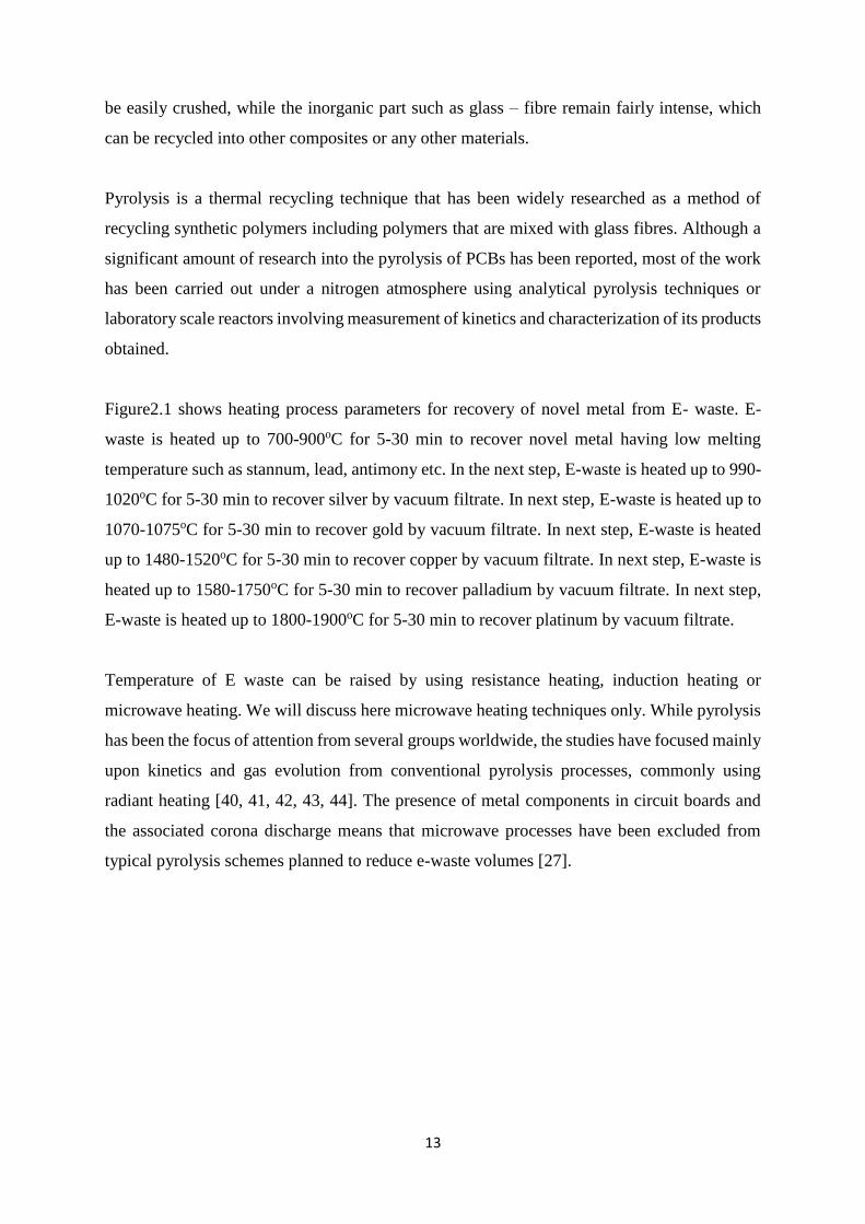
Figure2.1 shows heating process parameters for recovery of novel metal from E- waste. E-
waste is heated up to 700-900oC for 5-30 min to recover novel metal having low melting
temperature such as stannum, lead, antimony etc. In the next step, E-waste is heated up to 990-
1020oC for 5-30 min to recover silver by vacuum filtrate. In next step, E-waste is heated up to
1070-1075oC for 5-30 min to recover gold by vacuum filtrate. In next step, E-waste is heated
up to 1480-1520oC for 5-30 min to recover copper by vacuum filtrate. In next step, E-waste is
heated up to 1580-1750oC for 5-30 min to recover palladium by vacuum filtrate. In next step,
E-waste is heated up to 1800-1900oC for 5-30 min to recover platinum by vacuum filtrate.
Temperature of E waste can be raised by using resistance heating, induction heating or
microwave heating. We will discuss here microwave heating techniques only. While pyrolysis
has been the focus of attention from several groups worldwide, the studies have focused mainly
upon kinetics and gas evolution from conventional pyrolysis processes, commonly using
radiant heating [40, 41, 42, 43, 44]. The presence of metal components in circuit boards and
the associated corona discharge means that microwave processes have been excluded from
typical pyrolysis schemes planned to reduce e-waste volumes [27].

14
Figure 2.1Heating process parameters for recovery of novel metals [12]
In this regard, careful modeling of microwave interaction with typical e-waste components is
crucial to optimize a microwave assisted pyrolysis system. It may be mentioned that Sun and
co-workers have demonstrated the viability of the process [3, 27]. However, their studies have
been aimed at understanding the pyrolysis kinetics under microwave radiation and the group
used and adapted commercial microwave ovens for their work. As mentioned previously,
microwave interaction with matter is not trivial, and development of a cavity purposely built
for pyrolysis will require careful simulation and optimization, which is a gap area that this
thesis attempts to fill.
In history, there is a continuous quest for “mining” electronic waste for valuable materials. So
e-waste is either disposed of or transported often to underdeveloped countries where the
materials are either disassembled mechanically or incinerated. These processes can result in
toxic pollutants, as dioxins, furans, and lead, contaminating soil, air and water.
In literature it has been shown that the combination of microwave-induced pyrolysis and
mechanical processing is a promising way to recycle the waste printed circuit boards (WPCBs).

15
The mechanical process includes crushing and sink-float separation, and is very suitable for
metal reclamation from the microwave-induced pyrolysis residues. The economic assessment
for the combined treatment is huge, profitable and very promising to tackle the challenges
posed by the electronic wastes [103].
Rumana Hossain et. al. [104] have demonstrated a new technique, based on thermal
micronizing (TM), used for the controlled transformation of metals present in waste printed
circuit boards (PCBs) into value-added tin and copper-based alloys. The fast heating process
in a reducing atmosphere recovered tin-based alloy at 500 °C and copper-based alloy at 1000
°C from the waste PCB. Low-temperature heat treatment, short heating times, and decrease in
process steps made it possible to remove the lead with tin-based alloy effectively. The
technique prevented the lead evaporating to the atmosphere or diffusing in solid copper of
waste PCBs due to the low solubility of lead in copper.
Recovery of basic valuable metals and alloys from E-waste using microwave heating followed
by leaching and cementation process has been demonstrated by Rajendra Prasad Mahapatra et.
al. [105]. It has been found that microwave heat treatment followed by acid leaching is the best
technique to recover valuable metals from E-waste. The e-waste was first crushed and then the
sample was melted in microwave heat treatment to recover the valuable metal in the form of
metallic mixture. This mixture was further subjected to acid leaching process in the presence
of hydrogen peroxide to form leached liquor.
S.W. Kingman et. al. discussed the potential use of microwave technology as an energy-
efficient alternative to current heating technologies employed in the processing and treatment
of waste [106]. The process applications considered are the treatment and control of specific
and often problematic waste-streams, including scrap tyres and plastics, and the remediation of
contaminated land and groundwater. It has been concluded that there is significant potential for
microwave technology to be employed as an alternative heating source in the treatment of
waste streams and environmental remediation. However, several major limitations prevent
these technologies from being widely employed. These include the absence of sufficient data
to quantify the dielectric properties of the treated waste streams, and technical difficulties
encountered when upgrading successful laboratory or pilot-scale processes to the industrial
scale.
The review on the advances in the microwave treatment of minerals is discussed in details by
S.S. Srikant et. al. [107]. Microwave energy has gained worldwide acceptance as a novel
method for heating, sintering and phase transformation of minerals and materials, as it offers
16
specific advantages in terms of speed, energy / power efficiency, process simplicity, improved
properties and produces the finer microstructures. Different applications are explained on ores,
microwave assisted grinding, selective mineral liberation, possible exploitation in the area of
extractive metallurgy, phase transformation, enhancement of magnetic and electrical
separation, saving of energy, decomposition/ recycling of wastes. It explained that microwave
energy is a clean and eco-friendly process for obtaining the value added products as compared
to conventional methods.
2.2 Nuclear Wastes:
Nuclear power bears the promise of clean, sustainable energy. However, safe management of
nuclear wastes arising from reactor operations and subsequent reprocessing of spent fuel is
very important. Typically, nuclear waste is categorized as [16]:
1. High Level Waste (HLW) [Activity > 1Ci/lit]
2. Intermediate Level Waste (ILW) [1mCi/lit < Activity < 1Ci/lit]
3. Low Level Waste (LLW) [Activity < 1mCi/lit]
The Nuclear Power Programme in India is based on “closed fuel cycle”. Closed fuel
cycle involves reprocessing and recycling of Spent Nuclear Fuel (SNF) coming out of
nuclear reactors. During reprocessing, uranium and plutonium, constituting the bulk of the
SNF are separated and subsequently recycled. The remaining small portion constitutes
high level radioactive waste containing most of the fission products and minor actinides.
In the Indian context, ILW is treated by ion exchange and related processes, and it is then
concentrated into HLW for vitrification and LLW for low level waste treatment [45, 46].
Typically, high level wastes (HLW) are vitrified in suitable glass matrices, while intermediate
and low-level wastes are immobilized in cement and placed into near surface disposal facilities,
or diluted and discharged to the environment at concentrations prescribed by regulatory bodies
such as the IAEA or AERB [45].
Of particular concern in LLW management are long lived, highly mobile species such as 99Tc
[47]. 99Tc arising from spent fuel reprocessing is a major radiation concern owing to a
combination of high thermal fission yield (6%), long half-life (2.13 × 10⁵ years), high
environmental mobility in oxidized pertechnate form combined with radioactivity as a β –

17
emitter [48, 49]. Further, 99Tc presents a challenge to conventional high temperature
vitrification in a borosilicate glass matrix owing to its volatility at glass synthesis temperatures
[17]. Immobilizing 99Tc in concrete is not a satisfactory solution since the life of concrete waste
form is lower than the half -life of 99Tc (102 years vs 105 years). Trials of using prospective
geopolymer concrete mix are only expected to be complementary with encapsulation and not
stand alone type [108].
2.2.1 Management of Low Level Liquid Waste (LLW)
(a) Chemical treatment of LLW
Low Level Liquid wastes are generated from nuclear power stations and other nuclear facilities.
These wastes are treated in different ways for removal of radionuclides like 137Cs,90Sr,106Ru,
and 125Sb. The technique is called co-precipitation and it uses chemicals like barium chloride,
sodium sulphate, potassium ferrocyanide, copper sulphate etc. These chemicals are mixed with
LLW effluents in predetermined quantities at an optimum pH value [109]. The resulting
precipitate incorporating bulk of radioactivity is allowed to settle in clari flocculators. The
supernatant liquid depleted of radioactivity is then discharged after dilution and monitoring.
The sludge from the clari flocculator is further concentrated by decantation, filtration and
centrifugation. The resulting solids contain bulk of the radioactivity originally present in the
liquid waste. These solid cakes are further conditioned to convert into compacted mass before
disposal. Chemical reactions involved in the removal of various radionuclides by co-
precipitation are:
For removal of Cs+
CuSO4 + K4Fe (CN)6→ K2SO4 + K2CuFe(CN)6↓
For Removal of Sr++
Ba(NO3)2 + Na2SO4 → 2NaNO3 + BaSO4 ↓
3CaCl2 + 2Na3PO4 → 6NaCl + Ca3(PO4)2 ↓
For other radionuclides like actinides
Fe(NO3)3 + 3NaOH → 3NaNO3 + Fe(OH)3↓

18
(b) Reverse osmosis treatment of LLW
Membrane based processes like reverse osmosis and ultrafiltration are used for treatment of
low level liquid waste. These are generally employed in combination with other treatment
methods like chemical treatment or ion-exchange process for further improvement in the
decontamination factor defined by ratio of the radioactivity present in the waste treated to that
of the discharged effluent. The volume of waste is normally reduced by a factor of ten and
decontamination factor of 8-10 is achieved in this process.
2.2.2 Management of Intermediate Waste (ILW)
Characteristics of ILW generated during reprocessing are presented in Table 2.1.
Table 2.1 Characteristics of Intermediate Level Waste
Sr. No. Properties Value
1 Nature Alkaline
2 pH 9 −13
3 Gross -activity (mCi/L)
(137Cs, 90Sr, 106Ru, etc)
5 − 50
4 Gross -activity (mCi/L) 10−2 −10−4
5 Total dissolved solids (g/L)
(NaNO3, NaOH, Na2CO3, NaAlO2, etc)
100- 300
The following techniques are used for treatment of ILW
(a) Ion exchange process treatment for ILW
Ion exchange technique is used to remove specific radio-nuclide from the bulk of liquid waste.
Both natural and synthetic ion exchange materials are deployed. Naturally occurring ion
exchangers such as vermiculite, bentonite etc. are used mostly in site specific waste treatment
operations. Synthetic ion exchangers used are Resorcinol Formaldehyde Polycondensate Resin
(RFPR) [110] and Ammonium Molybdenum Phosphate (AMP) based composite resin [111].
A chemical formula of RFPR indicating exchangeable sites is shown in Figure.2.2.

19
Figure 2.2 Chemical formula of RFPR indicating exchangeable sites [110]
Due to the regenerative nature and high exchange capacities, synthetic ion exchangers are being
extensively used in India for treatment of liquid waste originating from spent fuel storage pools
and reprocessing plants. Processes based on synthetic ion exchangers lead to high reduction of
volume. These processes also give high decontamination factors.
A treatment process based on radionuclide separation by selective ion exchange is used
for the effective management of alkaline intermediate level waste (ILW).
(b) Cementation as treatment of ILW
Cementation is used for immobilization of radioactive concentrates and chemical sludge
generated during the treatment of LLW. It has universal application due to low cost and
operational simplicity [112]. In-drum mixing employing tumbler mixers, Ordinary Portland
Cement (OPC) is used in batch operations with waste to cement proportions of 1:1.5.
Cementation is also used for in-situ immobilization of intermediate level waste in specific cases
[113]. Cementation results in a large waste processing rate with extremely small exposure to
the radiation workers.
2.2.3 Management of High Level Liquid Waste (HLLW)
High-level radioactive liquid waste (HLLW) generated during reprocessing of spent nuclear
fuel is highly acidic in nature. This waste contains more than 99% of the total radioactivity
generated in the entire nuclear fuel cycle.

20
A three-step strategy involving immobilization, interim storage followed by ultimate
disposal has been adopted in India for management of High Level Waste (HLW).
Borosilicate glass matrix has been identified for immobilization of HLW owing to
optimal waste loading, adequate leach resistance and long term stability of the product
and the immobilised glass is known as vitrified waste product (VWP). Different types of
melters like metallic, Joule Heated Ceramic Melter (JHCM) have been successfully
deployed on an industrial scale for vitrification of HLW. A Cold Crucible Induction Melter
(CCIM) has also been developed for vitrification of HLW [114].
Process description:
Vitrification process is essentially a batch operation consisting of metering of pre-
concentrated waste and glass forming additives in the form of slurry/glass frit into the
heated process vessel located in a multi-zone furnace. A simplified flow-sheet of the
vitrification process adopted at Trombay is presented in Figure-2.3.
Figure 2.3 Process schematic for Vitrification of HLW [114]
The susceptor and the process vessel are made of high Ni-Cr alloy so as to withstand high
temperature, oxidizing and corrosive conditions. There is a freeze valve section at the
bottom of the process pot operable by an independent induction coil. These are heated by
an induction heating system. The level of liquid waste is indicated by the temperatures
sensed by the thermocouples located at different heights. The calcined mass is fused into

21
glass at about 1223K and is soaked at 1223-1273K for eight hours to achieve homogenization.
The molten mass is drained into stainless steel AISI 304L canister by operating the freeze
valve. The canister filled with VWP is allowed to cool slowly in an insulated assembly. This
is then welded remotely by Pulse-TIG method by remote welding machine. The schematic of
the metallic melter is shown in Figure 2.4.
Figure 2.4 Schematic of melters used for vitrification of HLW [114]
Vitrified waste canisters are further enclosed in a secondary stainless steel container
called over packs. These over packs are designed to contain radioactivity of the order
of 37000 TBq generating about 3-4 KW of decay heat. An elaborate off-gas cleaning
system consisting of condenser, scrubber, chiller, demister and absolute HEPA filter is used to
treat the gases before discharge through a tall stack (85-100 m). The plants are provided with
a central data acquisition and control system to monitor and control the critical process
parameters during vitrification operation. The whole operation is carried out in a hot-cell
having multiple compartments including concentration operation, furnace operation, welding
station and product storage. Remote handling gadgets like servo-manipulator, in-cell cranes
etc. have been developed indigenously and deployed to accomplish the entire operation.
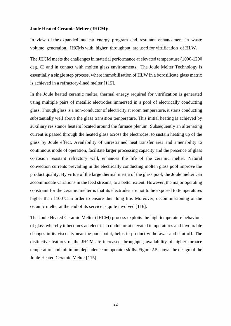
22
Joule Heated Ceramic Melter (JHCM):
In view of the expanded nuclear energy program and resultant enhancement in waste
volume generation, JHCMs with higher throughput are used for vitrification of HLW.
The JHCM meets the challenges in material performance at elevated temperature (1000-1200
deg. C) and in contact with molten glass environments. The Joule Melter Technology is
essentially a single step process, where immobilisation of HLW in a borosilicate glass matrix
is achieved in a refractory-lined melter [115].
In the Joule heated ceramic melter, thermal energy required for vitrification is generated
using multiple pairs of metallic electrodes immersed in a pool of electrically conducting
glass. Though glass is a non-conductor of electricity at room temperature, it starts conducting
substantially well above the glass transition temperature. This initial heating is achieved by
auxiliary resistance heaters located around the furnace plenum. Subsequently an alternating
current is passed through the heated glass across the electrodes, to sustain heating up of the
glass by Joule effect. Availability of unrestrained heat transfer area and amenability to
continuous mode of operation, facilitate larger processing capacity and the presence of glass
corrosion resistant refractory wall, enhances the life of the ceramic melter. Natural
convection currents prevailing in the electrically conducting molten glass pool improve the
product quality. By virtue of the large thermal inertia of the glass pool, the Joule melter can
accommodate variations in the feed streams, to a better extent. However, the major operating
constraint for the ceramic melter is that its electrodes are not to be exposed to temperatures
higher than 1100oC in order to ensure their long life. Moreover, decommissioning of the
ceramic melter at the end of its service is quite involved [116].
The Joule Heated Ceramic Melter (JHCM) process exploits the high temperature behaviour
of glass whereby it becomes an electrical conductor at elevated temperatures and favourable
changes in its viscosity near the pour point, helps in product withdrawal and shut off. The
distinctive features of the JHCM are increased throughput, availability of higher furnace
temperature and minimum dependence on operator skills. Figure 2.5 shows the design of the
Joule Heated Ceramic Melter [115].

23
Figure 2.5 Schematic of Joule heated ceramic melter for vitrification of HLW [115]
Cold Crucible Induction Melter (CCIM):
Vitrification technology based on cold crucible induction melter has developed to address
various requirements such as high temperature availability, high waste loading and
compatibility with new matrices like glass-ceramic.
It is emerging as a futuristic technology for vitrification of high level liquid waste. Besides
being compact and advantageous as in-cell equipment, it offers flexibility, susceptibility to treat
various waste forms with better waste loading and enhanced melter life. The cold crucible is
manufactured from contiguous segments forming a cylindrical volume, but separated by a thin
layer of electrically insulating material. The number and the shape of the segments and the
insulating gap between them must be optimized to minimize the power dissipation by induced
currents in the crucible, while ensuring cooling of the crucible. The schematic of the melter is
shown in Figure2.6. The glass melting in CCIM is shown in Figure2.7 [116].

24
Figure 2.6 Schematic of Cold Crucible Induction Melter [116]
Figure 2.7 Glass melting in engineering scale cold crucible set-up [116]

25
2.2.4 Microwave heating in Nuclear technology
Microwave heating is being successfully used in different applications related to medical,
domestic, industrial and commercial applications. In nuclear fuel technology also microwave
heating finds its use to melt and solidify the ash of incinerated wastes during MOX fuel
fabrication in Japan at JNC [58]. Hauck [30] discusses design considerations for Microwave Oven
Cavities.
2.2.4.1 Application of microwave heating for Conversion of Pu-U Nitrate Mixed
Solutions to Mixed Oxide Powder:
The microwave heating method was successfully used for a Process for Co-Conversion of Pu-
U Nitrate Mixed Solutions to Mixed Oxide Powder. The co-conversion process using a
microwave heating method has many excellent advantages, such as good powder
characteristics of the product, good homogeneity of Pu-U oxide, simplicity of the Process,
minimum liquid waste, no possibility of changing the Pu/U ratio and stable operability of the
plant compared to other method [117]. The flow sheet of the process of the co-conversion test
unit used is shown in Figure 2.8.
Figure 2.8 Flow sheet of the process for co-conversion of Pu-U nitrate solutions using
microwave heating method [117]
A constant volume of the mixed solution of Pu-U nitrate is supplied to a denitration vessel and
is heated by microwave energy. The mixed solutions are concentrated and denitrated
successively through vaporization of the nitric acid and thermal decomposition of the mixed

26
nitrates, and changed to PuO2-UO2 mixed oxide cake. Figure 2.9 shows a typical temperature
curve of the uranyl nitrate solution during the heated process with microwave power units.
Vaporization of nitric acid is started at about 110°C. Boiling of the solution continues for some
minutes at this temperature. After the concentration of the solution, thermal decomposition of
the nitrate occurs at about 300°C. By this decomposition the uranyl nitrate changes to UO2
[117].
Figure 2.9 Temperature curve of solution during de nitration reaction [117]
A detailed description about the development of the Microwave Heating Method for Co-
Conversion of Plutonium-Uranium Nitrate to MOX Powder can be found in [118]. There, it is
described that the efficiency of the microwave system and the product quality was increased
by using silicon nitride (Si3N4) dish for de nitration in place of SS dish.
2.2.4.2 Microwave heating in thorium fuel cycle
Microwave heating has also been attempted for its application in thorium fuel cycle in BARC.
This process can be effectively applied in aqueous processing steps, as water molecules are a
good absorber of microwaves [119]. It was found that the endothermic nature of the aqueous
process along with low pressure dissolution of ceramic oxides, concentration of liquids, de
nitration of nitrate solutions and amenability for liquid waste treatment, were the processes
where microwave heating could offer advantages. Extremely high absorption of microwaves

27
by oxides of uranium and plutonium, was noticed enhancing the scope of materials processing
in thoria based mixed oxide fuel fabrication during calcination, reduction, drying, dewaxing
and sintering. Microwave sintering improved the quality of fuel pellets, bringing down the
rejection rate. The microwave sintering was also found useful in recovery of rejects, chemical
analyses during fuel fabrication and solid waste treatment. It was concluded that microwave
heating techniques could play an important role at various stages in the chemical processing of
ThO2 and its mixed oxide fuel feed preparation, fabrication, scrap recovery and waste
treatment. The stainless steel cylindrical microwave cavity (tank) was recommended in the
pressurized (upto 40 psi) microwave dissolution of ThO2 and its mixed oxide fuels. Microwave
de nitration of solutions to oxide powders or gelation of nitrate solutions directly to
microspheres provided direct feed for fuel fabrication. The direct microwave sintering
technique for (Th,U)O2 and (Th,Pu)O2 were found to be effective in improving quality of
products as well as in reduction of maintenance work for glove-box and hot-cell. The
application of microwave technology in radioactive waste treatment streams seemed to hold
good promises.
2.2.4.3 Microwave heating in wet granulation of mixed oxide (MOX) powders
Similarly, work on a wet granulation of mixed oxide (MOX) powders prepared by the
microwave heating de-nitration method was also tried in Japan to fabricate MOX fuel pellets
for fast breeder reactors as an extremely simplified process. It is reported by Yoshiyuki Kato
[120] that an agitating granulator having three blades and a chopper was used in experiments
for performance evaluation. Characteristics and physical properties of the raw powder and
the granules were examined before/after granulation and the results were found to be very
encouraging.
2.2.4.4 Microwave heating in synthesis of sodium zirconium phosphate (NZP)
Microwave-assisted studies for low temperature solid state synthesis of sodium zirconium
phosphate (NZP), were also carried out in BARC for exploring potential candidate material
for immobilization and disposal of high level liquid nuclear waste, as reported by Naik et al.
[121]. Authors have mentioned that as during the vitrification process currently followed at
high temperatures of the order of 1150°C, oxides of long lived radionuclides such as Cesium,
Strontium, Tellurium, Ruthenium (Cs, Sr, Te, Ru) etc. get vaporised, posing serious
maintenance issues due to high radioactivity. It is therefore necessary to devise a process for
fixing these elements in solids at temperatures low enough. Three probable fission products,
namely, Cesium, Strontium and Tellurium were tried in the NZP matrix during its synthesis

28
at 450°C. Subsequently leaching studies were carried out on the fission product substituted
NZP sintered at 1000°C, in pure deionized water and also with 80% saturated brine solution
at temperatures of 30°C and 90°C. The effect of temperature and the nature of leachant on
the leaching rate did not indicate any systematic trend. The EDX analysis of the leached NZP
pellets showed that the leaching of the dopants was limited largely to the surface region of
the sintered pellets.
Considering the challenges in 99Tc management, research groups around the world have
attempted various methods for removal. These include adsorption on a reducing substrate,
trapping by ion exchange etc. Other options include reduction of 99Tc(VII) to 99Tc(IV) by a
suitable REDOX couple such as Fe2+/Fe3+, followed by mineralization in Goethite (FeOOH)
or Magnetite (Fe3O4) [18, 47]. The 99Tcbearing mineral form is usually a fine powder and
further dispersion concerns can be addressed by consolidation of the 99Tc bearing material into
a monolith. Such a monolith can be formed using a suitable, low melting glass. However,
suitable care must be taken to ensure that the 99Tc bearing mineral phase does not dissolve in
the glass melt, as this can again allow the reduced 99Tc to escape. In view of this, microwave
assisted heating will allow rapid melting of the glass, followed by solidification, preventing
dissolution of the 99Tcbearing crystalline phase. A similar approach using conventional heating
methods has been demonstrated for the formation of glass/ceramic composites for
immobilization of Actinides in titanate phases, which are then encapsulated in a durable
borosilicate glass. The “double encapsulation” of 99Tcis anticipated to reduce its mobility and
any remobilization risk.
2.3 Microwave Heating system Engineering :
The genesis of microwave heating, as an offshoot of radar technology, can be traced to the end
of World War – II. At that time, it was discovered that radiations in the 300 MHz to 300 GHz
range could produce heating in dielectric materials by polarization effect [24, 50]. With the
growth of consumer electronics, microwave ovens became more affordable and ubiquitous.
Indeed, over 95% of homes in developed countries have a domestic microwave oven [51].
Microwave heating for food warming applications developed rapidly, due to the improvement
in efficiency driven by a high heating rate. However, the non-uniformity of heating inherent in
microwave processes has deterred wider adoption. In the food processing industry, non-
uniform heating increases the likelihood of harmful microorganisms surviving in microwave
heated food products, as a result of which widespread uptake of the technology has been limited

29
[52, 21, 53]. The formation of hot and cold spots in the heated material is a result of microwave
interaction with the dielectric material placed in the cavity, and varies with material and cavity
design [54, 55, 56].
The term “Microwaves'' not only encompasses the range of frequencies from 300 MHz to 300
GHz, but also the techniques and concepts used for the manipulation and utilization of these
radiations [5]. Microwaves can be transmitted through hollow metal waveguides, focussed
using a high gain antenna and suffer deviation when travelling from one medium to the other
with different dielectric constants. Since microwaves are a part of the electromagnetic
spectrum, they propagate similar to light. They are reflected by polished metal surfaces and
pass through certain materials with minimal absorption, while suffering significant absorption
in others. Typically, materials with large water content such as food show high
absorbance/coupling with microwave radiations and consequently are heated efficiently. In
contrast, most ceramics and thermoplastic materials are poor absorbers [55, 5].
The energy, E, is related to the frequency, ν as follows [57]:
𝐸 = ℎ𝜈 =ℎ𝑐
𝜆 (2.1)
Where, h is Planck constant ,c is speed of light in vacuum, 𝜈 is frequency and 𝜆 is wavelength
.To prevent interference with telecommunication signals, heating applications are restricted to
27.12, 915 and 2450 MHz, which are known collectively as the Industrial, Scientific and
Medical (ISM) bands. Domestic ovens and laboratory systems generally work at 2.45 GHz.It
may also be mentioned that at frequencies below 100 MHz, conventional open wire circuits
can be used and the heating is known as radio frequency (RF) heating, with the object being
heated placed between the electrodes of a capacitor, as described in the short wave heating
demonstrations by Westinghouse [21]. At frequencies above about 500 MHz, wired circuits
are inapplicable and power is transferred to a metallic enclosure containing the object being
heated. The metallic enclosure is known as the applicator. This is the origin of the difference
between microwave theory and circuit theory [57].
Microwave wavelengths are comparable to the size of production and transmission elements.
Consequently, and in contrast to circuit theory, they cannot be treated as point objects
comparative to the wavelength used. At the other limit, they are not much larger than the
wavelength, invalidating treatment of the problem by geometric optics [57].

30
The wavelength of microwaves then implies that a detailed analysis of microwaves will require
both corpuscular aspects involving quantum mechanics and continuum wave-like aspects
utilizing the Maxwell – Heaviside equations. A deeper discussion of mathematics is not
presented here.
2.3.1 Microwave heating
In this method, microwaves are used to heat the E waste material. The microwaves are
electromagnetic radiation and the frequency range lies between 1 and 300GHz.These
microwave frequencies with different wavelengths are used for a wide variety of applications.
The domestic microwave applicators work on a frequency of 2.45 GHz. The frequencies
reserved by the Federal Communications Commission (FCC) for heating purposes in industrial,
scientific, and medical systems are 915 MHz and 2.45 GHz. However, some researchers
reported that the working frequencies for microwave materials processing furnaces are 915
MHz to 18 GHz [16-17].
As all electromagnetic waves, microwaves consist of electric and magnetic field components,
both perpendicular to each other. Generally, there are three qualitative ways in which a material
may be categorized with respect to its interaction with the electric field component of the
microwave field: (i) insulators, where microwaves pass through without any losses
(transparent), (ii) conductors, where microwaves are reflected and cannot penetrate, and (iii)
absorbers. Materials that absorb microwave radiation are called dielectrics, thus, microwave
heating is also referred to as dielectric heating.
There exist a number of mechanisms that contribute to the dielectric response of materials
(Thostenson and Chou, 1999). These include electronic polarization, atomic polarization, ionic
conduction, dipole (orientation) polarization, and interfacial or Maxwell-Wagner polarization
mechanisms. At microwave frequencies, only dipole and Maxwell-Wagner polarizations result
in the transfer of electromagnetic energy to thermal energy (Mijovicand Wijaya, 1990). In polar
organic-solvent systems at non-extreme temperatures, the dipolar polarization mechanism
accounts for the majority of the microwave heating effect, while in some carbon-based
materials is the interfacial polarization of the principal head. With respect to the former, dipoles
may be a natural feature of the dielectric or they may be induced (Kelly and Rowson, 1995).
Distortion of the electron cloud around non-polar molecules or atoms through the presence of
an external electric field can induce temporary dipoles. The dipoles in the material exposed to

31
the alternating electromagnetic field realign themselves approximately 2.5 billion times per
second (for a microwave frequency of 2.45 GHz). This movement results in rotation of the
dipoles, and energy is dissipated as heat from internal resistance to the rotation.
On the other hand, the Maxwell-Wagner polarization occurs at the boundary of two materials
with different dielectric properties, or in dielectric solid materials with charged particles which
are free to move in a delimited region of the material, such as π-electrons in carbon materials
(Zlotorzynski, 1995). When the charged particles cannot couple to the changes of phase of the
electric field, the accumulation of charge at the material interface is produced and energy is
dissipated in the form of heat due to the so-called Maxwell-Wagner effect (Zlotorzynski, 1995).
The response to an applied electric field is dependent on the dielectric properties of the material
(Thostenson and Chou, 1999). The polarization takes place when the effective current in the
irradiated sample is out of phase with that of the applied field by a difference (termed δ). This
difference defines the tangent loss factor, tan δ , often named the dissipation factor or the
dielectric loss tangent. The word “loss” refers to the input microwave energy that is lost to the
sample by being dissipated as heat. Thus, microwave energy is not transferred primarily by
convection or by conduction, as with conventional heating, but by dielectric loss. The tangent
loss factor is expressed as the quotient, tan δ =ε”/ ε’, where ε” is the dielectric loss factor,
indicative of the efficiency with which electromagnetic radiation is converted to heat, and ε’ is
the dielectric constant describing the ability of molecules to be polarized by the electric field.
A high value for tan δ indicates a high susceptibility to microwave energy. Because the
dielectric properties govern the ability of materials to heat in microwave fields, the
measurement of these properties as a function of temperature frequency, or other relevant
parameters (moisture content, density, material geometry, etc.) is important. But not only
microwave heating is a function of tan δ, but also other parameters related to the material, such
as ionic strength, specific heat capacity, thermal conductivity and emissivity, and related to the
applied field and the operating conditions have to be taken into account as well (Mingos and
Baghurst, 1991).
2.3.2 Microwave Heating vs Joule Heating:
When microwave power is used for heating of material this is known as microwave assisted
heating, these types of systems are in general known as microwave applicators. Most of the
industrial and domestic appliances are authorized to operate only at either 915 MHz or 2.45
GHz to avoid interfering with radar and telecommunication frequencies.

32
The use of microwaves for heating is well established in society, being used in domestic and
some industrial processes. However, there is potential for this technology to be introduced and
applied to many other industrial heating processes, which offers unique advantages not attained
with conventional heating. In this sense, microwave technology is being explored as one
method to assist in waste management.
In resistance heating and induction heating (conventional), heat is transferred from surface to
center by the phenomenon of conduction, convention, and radiations; whereas in microwave
heating, the atomic level heating is present, which gives volumetric heating in the processed
component. During microwave heating, the electromagnetic energy gets converted into heat
from within the material, which moves toward the outer direction from the core/center of
materials. The heating mechanisms for both the systems (conventional and microwave) are
shown in Figure 2.10.
This microwave heating mechanism offers many advantages over conventional heating due to
the following factors:
● The direct absorption of microwaves within materials allows volumetric heating which
produces enhanced diffusion rates, reduced power consumptions, and lower processing
times.
● These characteristics of higher heating rates and higher diffusion rates allowed
improvements in physical and mechanical properties of the microwave-processed
materials or components owing to which the formation of defects are lower.
● Further phenomenon of volumetric heating provides selective heating and uniform
heating, leading to decreased processing temperatures, reduced thermal gradient,
reduced heat-affected zone, and lower environmental hazards.

33
Table 2.2 Comparison between microwave and conventional heating
Microwave energy has become a newly-developing energy source in recent years. Since its
first application reported by Roy et al. [124], microwave heating technology and related
equipment were widely applied in both industrial and small-scale applications, such as the
microwave sintering of metal and alloy, and the processing of food, ceramics, composites, and
biomaterials, chemical and agricultural products. Many potential advantages have been
recognized in the area of materials processing. Microwave processing of materials has been
found to deliver enormous advantages over conventional processing methods in terms of
mechanical and physical properties of the materials. Microwaves heat the material from the
inside and can lead to saving enormous amounts of energy, since it is not necessary to heat the
container or the air between the heat source and the load material. Microwave processing can
facilitate the densification rate and particle size uniformity and can also promote improvement
in micro structural properties of materials, which cannot be observed in conventional processes.
However, non-uniform temperature distribution is the key problem of microwave processing,
which is related to structure of the cavity and the placement and physical parameters of the
materials. Non-uniform heating was due to the standing wave and the rapid decay of the
microwave. Based on the analysis, it was proposed that metallic stirrers turning tables and
movement of material employed in microwave ovens can reduce the degree of non-uniform
microwave heating [124].
Unfortunately, some limitations restrict the up-scaling of laboratory-based experiments to
industrial application. Microwave heating is liable to cause non-uniform temperature
Microwave Heating Conventional Heating
Energetic coupling Conduction/convection
Coupling at the molecular level Superficial heating
Rapid Slow
Volumetric Superficial
Selective Non Selective
Dependent on the properties of the
material
Less dependent

34
distribution. The hot spots (huge temperature gradient at a given location) and thermal runaway
(the uncontrollable temperature rise due to strong dielectric loss and temperature-positive
feedback of the material) caused by microwave non-uniform heating may occur when a high-
power microwave is applied on the processed materials. In some instances, it even leads to the
damage of material or even an explosion. Obviously, the problem of non-uniform heating has
become a bottleneck for the widespread exploitation of this technology.
Figure 2.10 Phenomenon of heat generation in (a) conventional heating and (b)
microwave heating [17]
The two conventional heating techniques used for waste treatment are Radiant heating and
joule heating. But both these techniques require local heating elements. As in microwave
heating no radiant heating is required which makes microwave heating much more reliable and
easier to maintain in material processing application. In case of joule heating a current is
directly passed through heating element which in turn produces heat, here heat generated is
directly given by I2Rt.A distinguishing feature of microwave heating is its volumetric nature
whereby the microwave power is dissipated in a dielectric and the electromagnetic energy is
converted directly to heat inside the sample as shown in Figure 2.11. This is in contrast to
conventional heating where heat enters the sample through its surface and is transferred
towards the center of the sample mainly by thermal conduction.

35
Figure 2.11 Temperature profile for Conventional and microwave heating in the cell[17]
2.4 Summary
E waste and nuclear waste generation, management along with different heating techniques
and methodologies have been discussed in this chapter. Microwave heating is considered as a
better option in comparison to conventional heating techniques for waste treatment from time
reduction and volume reduction point of view. Most of the studies have been aimed at
understanding the pyrolysis kinetics under microwave radiation and by adapting readily
available commercial microwave ovens for usage. But for microwave heating systems, in
between cavity design and overall material interaction with microwaves there are considerable
gaps in literature. As in case of e-wastes, while the process is viable, microwave heating
requires judicious cavity design and optimization using simulation tools. Indeed, both the
nuclear and e-waste management scenarios presented highlight the necessity to have a suitable
modeling and simulation study to optimize cavity design, which forms the thrust area of this
thesis. This thesis deals with dielectric material interaction with microwaves along with
optimization of cavity design for particular type of waste materials. A prototype Microwave
Heating System with optimized microwave cavity is also developed as an outcome of this work.

36
Chapter 3
MICROWAVE HEATING SET UP: DESIGN AND
MATHEMATICAL MODELING
The ‘heart’ of any microwave system is the applicator, comprising several sub-systems and
protection devices. Indeed, the mathematical treatment and computational protocols to
implement the same as discussed in the literature finally inform design consideration for the
applicator. As already stated, the present thesis describes microwave systems operating at
2450MHz, the allowed microwave industrial bands. This chapter provides an overview of the
components utilized in the microwave heating system, along with mathematical treatment and
equations which are important for design of microwave cavities.
3.1 Components of Microwave Heating Setup:
A block diagram of the microwave heating set-up is presented in Figure 3.1. The system consists
of the following components:
● Switching mode power supply
● Magnetron
● Circulator
● Directional Coupler
● Stub Tuner
● Microwave cavity
● Waveguides, Viewing Ports and Thermal Sensors
Figure 3.1 Block diagram of microwave heating system

37
In the following sections, a brief description of each component is discussed along with selection
criteria as relevant.
3.1.1 Switching Mode Power Supply:
A switching mode power supply (SMPS) is an electronic power supply that incorporates a
switching regulator to convert electrical power efficiently. Like other power supplies, a SMPS
transfers power from an AC source (often mains power) to different types of loads. In the set-up
presented, the Magnetron serves as the load. The high voltage power supply in the setup is a 19’’
power supply capable of supplying 4000 V DC output to the magnetron.
3.1.2 Magnetron (Microwave Generator):
Magnetron development as a practical microwave source can be traced back to World War II,
motivated by the necessity for high power microwave sources for radar transmitters. The cavity
magnetron is a high-powered vacuum tube that utilizes the interaction of an electron beam with a
magnetic field while moving through multiple cavities inside a circular structure. A picture of a
cavity magnetron is presented in Chapter 1. The cavity magnetron is a resonant structure, the
frequency of which is determined by the dimension of the cavity and the structure itself. The
magnetron is a cross field device which works as an oscillator. Due to interaction of electrons
with the electric and magnetic fields, microwave oscillations are generated. Only those oscillation
modes which are in resonance with the cavity sustain and the others are rapidly damped.
Figure 3.2 Internal structure of magnetron [123].
As shown in figure 3.2, a cylindrical cathode is there in the center of magnetron and after an
annular gap a cylindrical metallic block with number of slots acts as anode. These slots act as

38
resonant cavity. In figure 3.2, a represents cathode radius of magnetron and b represents anode
radius of magnetron.
Frequency of operation for microwave source is 2450 MHz ± 25 MHz. The power output is
adjustable between 0 and 1200 W.
3.1.3 Circulator:
A microwave circulator is a waveguide based passive multiport device, in which a wave can flow
only in one direction. In this device if power is input at nth port it flows to (n+1)th port. Three or
four port circulators are ubiquitous. In the case of a three-port circulator, a signal applied to port
1 only flows to port 2; a signal applied to port 2 only flows to port 3; while a signal applied to port
3 will emerge from port 1, as shown in Figure 3.3. In our case, a matched load with water cooling
is connected at port 3. This load serves as a protection for the Microwave Source in case of
reflections from the load. This is an important consideration in case of e-wastes where the printed
circuit boards may contain metal terminals and contacts that can create a corona discharge, which
may damage the magnetron.
In other words, the circulator and the matched load serve as a nonreciprocal transmission device,
which protects the magnetron and the load in case of an impedance mismatch. It may be
emphasized that impedance mismatch can be a significant problem in waste management
applications as demonstrated in this thesis due to the heterogeneity of most waste constituents.
Figure 3.3 RF circulator ports.

39
3.1.4 Directional Coupler:
Directional couplers are generally four-port microwave circuits, where port 1 and port 2 constitute
the primary waveguide/primary circuit while port 3 and port 4 constitute the secondary
waveguide/secondary circuit. Directional couplers may consist of waveguide junctions or micro-
striplines in case of Printed Circuit Board (PCB) based circuits. In our case we have used a
waveguide based directional coupler. The coupling process generally occurs within a quarter
wavelength or a multiple of a quarter wavelength portion of the device. Directional coupler which
is used in microwave heating systems is a waveguide based directional coupler. Its port
configuration, as shown in Figure 3.4, for this coupler is defined as per the list given below:
Input (Port 1, Incident),
Transmitted (Port 2, Output),
Coupled (Port 3, forward coupled port), and
Isolated (Port 4, Reverse coupled port).
The other ports on the directional coupler are normally more suited for lower powers as they are
only intended to carry a small proportion of the main line power. Ports 3 and 4 may even have
smaller connectors to distinguish them from the main line ports of the RF coupler. Often the
isolated port is terminated with an internal or external matched load. Coupling factor for the
directional coupler used in our system is 60.1 dB.
Figure 3.4 Four port directional coupler.
3.1.5 Stub Tuners:
Stub tuners are basic laboratory tools used for matching load impedances to provide for maximum
power transfer between a generator and a load, and introducing a mismatch into an otherwise

40
matched system. In this case, the generator is the magnetron and the load can be a dielectric mix
of e-waste or n-waste (Refer Chapter 5& 6). Tuning the microwave unit is essential to achieve the
best use of energy, protect the generator and also minimize reflection and thereby mitigate
possible operating issues such as undesired overheating of the structure. In our microwave heating
setup, a three stub tuner is used.
In figure 3.5, a single stub tuner and double stub tuner are shown, as they are simpler for analysis.
A stub is a shorted transmission line of variable length which is connected with transmission line
mostly in shunt configuration, its position on main transmission line is chosen judiciously for
matching of transmission line impedance with load. In case of single stub tuner length of stub is
l, its position on main line and its length can be varied for proper matching of a load with
transmission line. In case of double stub tuner,l1 and l2 are lengths of first and second stub
respectively, d is separation between two stubs, YL is load admittance. Double stub tuner provides
higher degree of freedom in matching as there are multiple parameters available for adjustment.
Three stub tuner which is used in our system provides higher flexibility in impedance matching.
A Stub tuner functions as an impedance matching device by manipulating the EM fields inside
the waveguide by adjusting the depth of metal stubs placed at specific guide lengths. A stub tuner
in a microwave heating system is used for the following purposes:
Figure 3.5 (a) Double stub tuner(b) single stub tuners [123].

41
Figure 3.5(c) Three stub tuner
1. Match waveguide line to its load,
2. Minimize signal Loss,
3. Maximize power handling, and
4. Cancel out reactive component of load to be matched.
It consists of series, Shunt, open circuit and short circuit configurations.
For selection of stub tuner, following criteria are used
1. Stubs material: generally high conductivity metals and alloys,
2. Waveguide type: Type of waveguide for which stubs are designed,
3. Frequency, and
4. VSWR (Voltage Standing Wave Ratio): function of the reflection coefficient, which
describes the power reflected.
3.1.6 Microwave Cavity:
A microwave cavity or radio frequency (RF) cavity is a special type of resonator, consisting of a
closed (or largely closed) metal structure that confines electromagnetic fields in the microwave
region of the spectrum. The structure is either hollow or filled with a dielectric material. This
cavity can be a single mode or multi-mode cavity depending on the requirement of the heating
process. Since our cavity design has been optimized to allow both e-waste management and
encapsulation studies of nuclear waste (surrogate), a multi-mode cavity has been preferred to
allow heating of heterogeneous loads.
3.1.7 Wave guides, Viewing Port and Thermal Sensors:
Waveguides are used to bring microwave energy from the magnetron to the cavity. These
operate on the principle of total internal reflection to minimize power loss while the
microwaves are brought to the cavity. Camera viewing port and thermal sensors are used for

42
visual and thermal recording of the process. For temperature sensing and recording, a
thermocouple along with a digital indicator is being used while an Infrared (IR) sensor serves
as a backup sensor for this setup.
3.1.8 Calibration and tuning procedure:
As per standard test procedure, the cavity is calibrated before putting it into the microwave
heating set up. The cavity has been mathematically modeled and its frequency determined from
simulation (Refer Chapter 4). After setting up the cavity and all other devices as per the setup
shown in the block diagram, calibration and tuning procedures were initiated. Measurement of
forward power at the directional power ensures that adequate power is delivered to the load
under operational conditions. The stub tuner is then used to optimize forward power versus
reflected power depending upon the load. Zero bias Schottky diodes are used for conversion of
microwave signal to DC signal. This DC signal is then measured on an analog power meter
setup. This power meter and Schottky diode setup is calibrated before connecting them in the
actual setup.
3.1.9 Fume Hood:
A fume hood is used for housing this complete microwave heating setup. In the fume hood,
water connections for matched load at the circulator are provided. Power supply for the
magnetron is kept outside the fume hood. Fume hood acts as a ventilation device for microwave
heating setup so that exposure of personnel to hazardous gases can be minimized. The fume
hood allowed confident handling of e-wastes since hazardous gases, if any, were handled by
the scrubbing equipment associated with the fume hood. Detailed technical specifications of
the fume hood along with other devices are given in the appendix -1.
Figure 3.6 Microwave heating set-up within a fume hood

43
3.2 Microwave Cavity Design:
A microwave cavity can be either cylindrical (Circular Cross-section) or cuboidal (Rectangular
Cross Section) in shape depending on the requirement of application. In general, a rectangular
microwave cavity finds more frequent usage for domestic and industrial applications [59, 60].
In a rectangular microwave cavity, standing wave field distribution is formed depending on the
type of feed provided. For any rectangular microwave cavity, there may be multiple resonances
excited in a frequency band. These resonance frequencies are the Eigenmodes of the cavity. To
achieve good heating performance, a cavity should have a large distribution of resonant
frequencies within the bandwidth of the source. This is ensured by calculating the number of
Eigenmodes of the designed cavity lying in the frequency bandwidth of source. Ensuring a
large number of Eigenmodes in the source bandwidth allows good heating performance [57,
59, 60, 61]. Some methods for improving the uniformity of microwave heating include the use
of mode stirred, phase shifting method. However, the objective of this thesis has been the
establishment of feasibility of microwave heating for heating of e-waste and n-waste. A
schematic sketch of a microwave cavity with waveguide and load is presented in Figure 3.7.
Figure 3.7 Multimode Cavity with a rectangular load placed within.
For any rectangular cavity, its mode indices are represented by l, m and n indicating
respectively the number of half wave cycles in x, y and z directions of cavity. Field patterns
for resonant modes differ according to the mode as shown in Figure 3.8.

44
3.2.1 Multimode Microwave Cavity:
Multimode microwave cavity has been chosen in microwave applicator setup. Rectangular
cavity resonator in multimode has been used in this case; multimode indicates the presence of
multiple resonant modes in the required frequency band. This section discusses the field
equations in a rectangular cavity resonator. In case of a rectangular cavity resonator, the
geometry of the cavity is like a rectangular wave guide with cross-section in XY plane with
dimensions a and b respectively and it is terminated in Z plane by two metallic plates at distance
d. The electromagnetic fields inside the rectangular cavity must satisfy the boundary conditions
for electric and magnetic fields. These boundary conditions are: the electric components
tangential to metallic walls must be zero (Et=0) and magnetic fields normal to metallic walls
must be zero (BN=0)[60].
In case of rectangular resonator, zero tangential electric field condition must be satisfied at the
four walls of the waveguide. In the z-direction, we can conveniently choose a harmonic
function in z to satisfy the boundary conditions at the two metallic plates in the z direction of
the cavity.
Functions of these fields can be chosen in case of TE and TM modes by the set of equations
given in the following. In case of TE mode all the field functions can be calculated from Hz
given as [59].
Figure 3.8 Field patterns of different resonant modes inside rectangular cavities [62].

45
𝐻𝑧 = 𝐻0𝑧𝑐𝑜𝑠 (𝑙𝜋𝑥
𝑎) 𝑐𝑜𝑠 (
𝑚𝜋𝑦
𝑏) 𝑠𝑖𝑛 (
𝑛𝜋𝑧
𝑑)
(3.1)
Equation (3.1) describes the TElmn mode, where l=0, 1, 2, 3... represents the number of half
wave cycles in x direction, m=0, 1, 2, 3... represents the number of half wave cycles in y
direction, and n=0, 1, 2, 3... represents the number of half wave cycles in z direction. In case
of the TMlmn mode, all the field functions can be calculated from Ez given as [60]
𝐸𝑧 = 𝐸0𝑧𝑠𝑖𝑛 (𝑙𝜋𝑥
𝑎) 𝑠𝑖𝑛 (
𝑚𝜋𝑦
𝑏) 𝑐𝑜𝑠 (
𝑛𝜋𝑧
𝑑)
(3.2)
Assuming a lossless dielectric, the resonant frequency of a rectangular cavity can be
expressed as
𝑓𝑟 =1
2√𝜇휀√(
𝑙𝜋
𝑎)
2
+ (𝑚𝜋
𝑏)
2
+ (𝑛𝜋
𝑑)
2
(3.3)
For an air filled cavity, 1/(√𝜇휀) can be replaced with 𝑐, the speed of light in vacuum [61].
The idealized cavity for which the above solutions are strictly valid is closed on all sides and
is known as a pillbox cavity. All practical cavities have one or two openings in the cavity walls
for waveguide feeds. Though the above given solutions become approximate for practical
cases, they serve as a good initial analytical solution for rectangular cavities. For exact
Figure 3.9 Rectangular resonator cavity and variations for TE101 and TE102 mode fields [60].

46
solutions, full wave analysis using software simulation computer aided design (CAD) packages
are used [63]. A visualization of modes in a rectangular pillbox cavity is illustrated in Figure
3.9. Solution of these wave equations has been dealt in detail in appendix 2.
3.2.2 Quality Factor of a Cavity Resonator [57, 59, 60]:
Frequency selectivity of a cavity resonator is represented by quality factor Q. Quality factor of
a cavity is defined as
𝑄 = 2𝜋𝑚𝑎𝑥𝑖𝑚𝑢𝑚 𝑒𝑛𝑒𝑟𝑔𝑦 𝑠𝑡𝑜𝑟𝑒𝑑
𝑒𝑛𝑒𝑟𝑔𝑦 𝑑𝑖𝑠𝑠𝑖𝑝𝑎𝑡𝑒𝑑 𝑝𝑒𝑟 𝑐𝑦𝑐𝑙𝑒=
𝜔𝑊
𝑃
(3.4)
where W is the maximum stored energy and P is the average power loss.
For resonant frequencies, the electric and magnetic energies are equal in magnitude and are at
90 phase difference. This implies that when magnetic energy is zero, electric energy is
maximum and when magnetic energy is maximum, electric energy is zero. By integrating the
energy density over the volume of resonator, total energy stored in the resonator can be
calculated as follows:
𝑊𝑒 = ∫휀
2|𝐸|2𝑑𝑣
𝑜
𝑣
= 𝑊𝑚 = ∫𝜇
2|𝐻|2𝑑𝑣
𝑜
𝑣
(3.5)
where 𝑣 denotes the volume of the cavity, ε and μ are respectively the electric permittivity and
magnetic permeability of dielectric material of cavity, while|𝐸| and |𝐻| respectively represent
the peak values of electric and magnetic field intensities.
The average power loss in the resonator can be evaluated by integration of power loss density
over the inner surface of resonator. Thus
𝑃 =𝑅𝑠
2∫ |𝐻𝑡|2𝑑𝑠
𝑠
𝑠
(3.6)
Using (3.5) and (3.6), the quality factor can be expressed as
𝑄 =𝜔𝜇 ∫ |𝐻|2𝑑𝑣
𝑜
𝑣
𝑅𝑠 ∫ |𝐻𝑡|2𝑑𝑠𝑠
𝑠
(3.7)
Equation (3.7) can again be approximated to:

47
𝑄 =𝜔𝜇
2𝑅𝑠 (3.8)
Any resonator is always coupled to a load and the quality factor for a loaded cavity denoted as
𝑄𝑙 is calculated using
1
𝑄𝑙=
1
𝑄0+
1
𝑄𝑒
(3.9)
where Qe represents the external Q factor and is function of load coupled with the cavity, Q0 is
quality factor of unloaded cavity.
3.2.3 Dielectric Properties [57, 59, 60]:
The relative complex permittivity of a material is expressed as follows:
휀∗ = 휀′ − 𝑗휀′′ (3.10)
where 휀′ and 휀′′ are the dielectric constant and the dielectric loss factor respectively. 휀′ is the
ability of the material to store electrical energy, while 휀′′ indicates the ability of the material to
dissipate stored electrical energy as heat.
Therefore, materials with a high dielectric loss factor are heated more easily in a microwave
furnace. The energy dissipated to heat, relative to the total electrical energy stored is
characterized by the dielectric loss tangent expressed as
𝑡𝑎𝑛𝛿 = 휀′′
휀′ (3.11)
The greater the value of 𝑡𝑎𝑛𝛿, the greater is the fraction of total stored energy dissipated as
heat. The power dissipated per unit volume in a lossy material is calculated by following
formula [57]:
𝑃𝑉 = 2𝜋𝑓휀0휀′′𝐸2 (3.12)
In equation (3.11), 𝑃𝑉 is the power dissipated per unit volume (W.m-3), 𝑓 represents the
frequency in Hz, 휀0 is the permittivity of free space (8.85 × 10⁻¹² F.m-1) and 𝐸 is the electric
field strength in the material (V.m-1). It may be mentioned here that various polarization
mechanisms such as dipole, electronic, atomic and Maxwell-Wagner polarization mechanisms;
in addition to conduction contribute to dielectric loss. Further, power dissipation due to the

48
magnetic field component can be neglected in case of materials with magnetic permeability
close to that of free space (µ0 = 4𝜋 × 10−7 N.A-1). Heating due to magnetic components can
be exploited by using ferrites, which are indeed used in microwave susceptors. From equation
(3.11), it is evident that modeling the heating produced in a material by microwaves requires
knowledge of microwave power dissipated in a dielectric material. Dielectric loss mechanism
has been explained in detail in appendix 2.
3.2.4 Lambert’s Law:
Computing the microwave power dissipation in a dielectric material can be simplified by
resorting to Lambert's law. Lambert's law assumes that the microwave energy is incident
normal to the surface and dissipates energy exponentially as it penetrates the dielectric material
[64].
Therefore,
𝑃(𝑥) = 𝑃0𝑒−2𝛽𝑥
(3.13)
Where, 𝑃(𝑥) represent the power dissipation at a depth 𝑥 (m) in W and 𝑃0 represents the
incident power in W and 𝛽 (m-1) is the attenuation constant, which depends upon the frequency
of the radiation (Hz), the velocity of the radiation (m.s-1) and 𝑡𝑎𝑛𝛿. Computationally, the
Lambert’s law is more economical since it dispenses with electric field distribution within the
material [65]. However, the Lambert’s law relies upon the following simplification:
1. Semi-infinite sample size,
2. No consideration of standing wave effects, and
3. Microwave energy penetration in one dimension only.
3.3 Maxwell’s Equations:
In case of the present work, the above assumptions are invalid and we defer the Lambert
treatment of the problem. Instead, we solve Maxwell's equations. Deduced by Maxwell based
upon the empirical experiments in electricity and magnetism, the following equations represent
the Maxwell’s equations in the differential form as formulated by Heaviside [57, 60]:
𝛻. 𝐷 = 𝜌 (3.14a)
𝛻. 𝐵 = 0 (3.14b)

49
𝛻 × 𝐸 = −𝜕𝐵
𝜕𝑡
(3.14c)
𝛻 × 𝐻 = 𝐽 + 𝜕𝐷
𝜕𝑡
(3.14d)
where,
𝐽 = 𝜎(𝜔)𝐸(𝑡) (3.15 a)
𝐷 = 휀(𝜔)𝐸(𝑡) (3.15 b)
𝐵 = 𝜇𝑚(𝜔)𝐻(𝑡) (3.15 c)
The terms used in the above expressions and their units are indicated in Table 3.1.
Table 3.1: Disambiguation of terms in equations (3.14) and (3.15) with their respective units
Term Significance Unit
D Electric Flux Density C.m-2
ρ Electric charge density C.m-3
B Magnetic Flux Density T
E Electric field intensity V.m-1
H Magnetic field intensity A.m-1
J Current flux/Current Density A.m-2
σ Electrical conductivity S.m-1
ω Angular frequency rad.s-1
ε Permittivity F.m-1
µm Magnetic permeability H.m-1
For the work reported in this thesis, Maxwell's equations were solved numerically to establish
the field distribution and the field distribution was used to estimate temperature of the material
with assumptions made about the sample’s emissivity.

50
Based upon the discussion above, it is evident that the heating pattern and efficiency of a
microwave heating system are determined by the applicator [61]. In view of this, we discuss
single mode and multi-mode applicators.
A single mode cavity is an applicator designed to operate in a single resonant mode. The
dimensions of the cavity are chosen such that the resonant frequency of this mode coincides
with the frequency of the source when the applicator is loaded. The field distribution within
the cavity can often be determined analytically, so the cavity can easily be designed to provide
the desired heating characteristics [61]. While the field distributions can be calculated
analytically, there are still certain parameters that are difficult to determine in this way. It is
possible that the loading will cause some higher order modes to be excited in which case the
field pattern will deviate from that of the dominant mode [62].
In contrast, a multimode cavity is simply a metal enclosure, generally rectangular in shape,
which is capable of supporting a large number of resonant modes. A feed system is incorporated
to couple the cavity to the source of microwave energy. Multimode cavities are capable of
accepting a wide range of loads with different geometries and material properties [63]. This
flexibility has made them the most widely used type of applicator, with the standard domestic
oven being of this type. However, the large number of possible modes makes this type of
applicator particularly difficult to analyze [61].
Irrespective of the cavity, assuming rectangular geometry, the modes obey
(𝑙𝜋
𝑎)
2
+ (𝑚𝜋
𝑏)
2
+ (𝑛𝜋
𝑑)
2
= (⍵
𝑐)
2
(3.16)
where, ⍵ is the resonant frequency of the mode and c is the speed of light.

51
Of course, during experiments the cavity is never empty. It is well known that the Q for an
empty cavity is much greater than that for a loaded cavity. Further, loaded cavities have a larger
number of modes present and these modes are not sharp, but exhibit a broad frequency
response. This behavior of the loaded cavity is shown in Figure 3.10. The presence of multiple
modes and their interaction with the material being heated limits analytical methods.
Figure 3.10 Resonant modes in a loaded and unloaded cavity [57].
A common practice for designing multimode applicators is to simply produce a cavity which
has the largest number of modes when empty. Since the number of modes present increases
when loaded, it is obvious that the large number of modes will overlap to produce uniformity.
3.4 Applicator Design [61]:
Microwave applicator design is very important as it will decide the heating performance of an
applicator for a prescribed load. However, design of single mode cavities is quite
straightforward and can be done analytically. In case of multimode cavity-based applicator
design, a more empirical and experience-based approach is called for. The field pattern in a
multimode applicator is determined by both the nature of the load and the size of the cavity. It
is therefore impossible to predict the exact field pattern for an arbitrary load without carrying
out a full solution of Maxwell’s equations for the loaded cavity. Since it is often the case that
no two loads are identical, this solution will apply only to the load that has been modeled. The

52
position of the load in the cavity will also affect the field pattern, a change of only a few
millimeters being sufficient to alter the distribution. Despite these difficulties it is still possible
to gain useful insights from simulations of loaded multimode cavities. One can, for example,
determine the degree of sensitivity of the system to various parameters, such as the source
frequency, feed position, load position or dielectric properties. It is also possible to test different
applicator designs against a set of loads, varying the dimensions and observing the effects. The
feed system is another area that can be addressed since small changes in the feed can produce
large changes in the way the cavity modes are excited. Simulation can then allow the designer
to experiment with various changes to a feed design, while keeping all other factors constant.
The allocated microwave frequencies for industrial usage are 915 MHz and 2.45 GHz. These
frequencies in microwave applicators are invariably generated using a magnetron as a
microwave source. To allow for frequency spread, a tolerance of ±10 MHz at 915 MHz and ±
50 MHz at 2450 MHz is allowed respectively. This frequency variation of source can
sometimes result in significant change in heating performance. Using a multimode cavity along
with a tuner device compensates for these frequency changes and provides a good heating
performance over the prescribed bandwidth of the microwave generator. Out of the two
frequencies, 2.45 GHz has been chosen as source frequency in our case. This is motivated by
the size dependence of the cavity on the wavelength λ. Using the lower frequency band may
result in a large and bulky applicator. It will also cause the cavity size to increase beyond 1 m
range at 915 MHz frequency which becomes impractical for laboratory scale microwave
heating systems.
3.5 Simulation Techniques:
As discussed previously, we used Maxwell's equations for determining the electric field in the
cavity. We use a Finite Integration Technique (FIT) [66], although Finite Difference Time
Domain (FDTD) [67], integral equation methods [68], Finite Element Method (FEM) [69] and
modal methods [70] have also been used by others.
Indeed, (3.14) in three dimensions gives rise to six coupled equations for electric and magnetic
fields. The most common analytical method includes the Transfer Matrix Function (TMF) [71]
and the iterative eigenfunction approach [72]. It has been shown in the literature that non-

53
homogeneous multi-layered stacks can be investigated using the transfer matrix method
(TMM) [73]. TMM solutions can also be used to treat problems involving frequency dependent
dielectrics. It may be mentioned here that Mie scattering theories are finding application in
biological systems and remote sensing [61]. However, the utility of these analytical approaches
is questionable for non-spherical objects. Further, the analytical methods listed above are
tractable only for simple geometries and more complex shapes require a numerical solution-
based approach to equations 3.14 and 3.15 [61].
Broadly, numerical solutions to equations 3.14 and 3.15 fall into one of three categories [74]:
1. Volume and surface integral equations method,
2. Differential equations method, and
3. Modal methods.
3.5.1 Volume and Surface Integral Equations Method [74]:
The volume and surface integral equations method includes the method of moments (MoM)
and the discrete dipole approximation (DDA). Using these methods, the integral forms of (2.15)
are transformed into a system of linear equations, which are then solved directly using
approaches such as LU factorization, Gaussian elimination (GE) or conjugate gradient (CG).
MoM considers discretization of subject structures, while not requiring discretization of the
free space around the scattered. In addition to being computationally demanding, the MoM
approach is best suited to conducting arrays such as antennae. The DDA approach, first
introduced in 1964 by DeVoe is useful to study scattering from spherical particles, which are
intractable in the Mie theory approach. The DDA method is best suited to materials with a low
dielectric constant, and the iterative solution scheme becomes computationally bulky for
large/heterogeneous objects. Additionally, the T-matrix, null matrix method (NMM) and
multipole method (MPM) have also been discussed.
3.5.2 Differential Equations Method [74]:
The differential equations method includes the finite element method (FEM), Finite Difference
Time Domain (FDTD) and Finite Integration Technique (FIT). We will briefly review the work
reported on each of these techniques.

54
3.5.2.1 FEM:
Unstructured grids form the basis of the FEM approach. The FEM approach breaks up a
continuous domain into a number of sub-domains, where the unknown function is represented
by an interpolation function. The variational principle then yields a series of algebraic
equations. These boundary value problems are then solved by direct (brute force) or iterative
solution techniques. The “finite elements” are constructed using piecewise geometrical
functions on geometrical sub-domains. The grid geometry (square, prisms, polyhedral etc.) can
be chosen according to the problem.
The advantage and limitation of FEM is the use of an unstructured grid. The use of such a grid
allows high flexibility with respect to object geometries and allows handling of discontinuous
media. However, FEM discretization on an unstructured grid leads to a large number of
unknowns, which makes it challenging to find an appropriate solver. Further, time harmonic
Maxwell’s equations are not easily discretized as the corresponding matrix of linear equations
has a large number of conditions. A significant problem is the formation of singularities near
sharp edges while solving Maxwell's equations. While an adaptive-unstructured grid is known
to minimize such singularities, these come at the price of reduced convergence rate for an
iterative solver with commensurate increase in computational time.
3.5.2.2 FDTD:
This method is one of the more popular methods to solve Maxwell’s curl equation for present
purposes, but (3.14 d) also more generally is the FDTD developed by Yee [75]. In this method,
all spatial and temporal derivatives of Maxwell's equations are approximated to finite-
difference expressions. In his original work, Yee’s algorithm consists of a Cartesian grid with
structured cells, where electric and magnetic field components are arranged in a staggered
manner. This pioneering work considered a rectangular grid with spatial grid
sizes ∆𝑥, ∆𝑦 and ∆𝑧. The corresponding space point lattices are:
(𝑥, 𝑦, 𝑧) = (𝑖∆𝑥, 𝑗∆𝑦, 𝑘∆𝑧 )
(3.17)
where, 𝑖, 𝑗, 𝑘 = 0, 1, 2 ….
For a time step size ∆𝑡, the time derivative of an arbitrary quantity can be discretized by
invoking the central finite-difference equation as follows:

55
𝜕𝑈(𝑥, 𝑦, 𝑧, 𝑡)
𝜕𝑡=
1
∆𝑡[𝑈𝑛+
1
2(𝑖, 𝑗, 𝑘) − 𝑈𝑛−1
2(𝑖, 𝑗, 𝑘)] + 𝑂[(∆𝑡)2]
(3.18)
The curl operator can then be expressed as:
𝛻𝑥 × 𝑈(𝑥, 𝑦, 𝑧, 𝑡)
= 1
∆𝑦[𝑈𝑧
𝑛 (𝑖, 𝑗 + 1
2, 𝑘) − 𝑈𝑧
𝑛 (𝑖, 𝑗 − 1
2, 𝑘)]
− 1
∆𝑧[𝑈𝑦
𝑛 (𝑖, 𝑗, 𝑘 + 1
2) − 𝑈𝑦
𝑛 (𝑖, 𝑗, 𝑘 − 1
2)]
+ 𝑂[(∆𝑦)2 + (∆𝑧)2]
(3.19)
Maxwell's equations are then solved by time stepping. In this case, a plane wave propagates
through the medium (discretized) and the field components are updated at each time step. To
ensure convergence, the time step is limited to a factor of the spatial mesh size chosen, known
as the Courant-Freidrich-levy (CFL) [74, 76] condition given by
∆𝑡 ≤ 1
𝑐(√
1
∆𝑥2+
1
∆𝑦2+
1
∆𝑧2)
−1
(3.20)
Unlike the previous FEM method, FDTD is matrix free and consequently dispenses with an
iterative solver. Also, the method is simpler, faster, computationally more economical and
amenable to parallelization. While the “time staircase” as expressed in (3.20) is possible for
simple geometries, complex shapes and heterogeneous materials can prove challenging.
3.5.2.3 FIT:
The FIT technique was first developed in 1977 [77] and utilizes a discretization protocol similar
to FDTD. However, in this method, Maxwell's equations are transformed into a system of linear
equations. This results in significantly improved treatment of interfaces and challenging
geometries. The relevant mathematics for this will be developed in Chapter 4. The FIT method

56
has the same overall advantages as the FDTD method including simple implementation and
parallelization. However, since FIT employs discrete volume discretization of the Maxwell’s
equations, Faraday’s law is satisfied on the domain and each discretization cell. Similar to
FDTD, FIT time steps are also constrained by the CFL condition as given in (3.23). Therefore,
if a small mesh size is required, then the number of time steps also increases, making the
calculations computationally bulky.
3.5.3 Modal Methods [70]:
The modal methods are not of interest in the type of problem studied in this thesis, but are more
applicable for the analysis of electromagnetic waves in periodic structures. However, we
present a brief overview in the interest of completeness. This method converts Maxwell's
equations into a system of linear equations in Fourier space. Toward this, the domain is
discretized into rectangular slices and the field in each slice is computed. The field and material
properties of each slice are represented by a Fourier series, which leads to an eigenvalue
problem to be solved for each slice.
While the analysis yields accurate results for rectilinear surfaces, curved surfaces and edges
cause divergence, or must be modeled with a larger number of layers, which can become
computationally demanding and in case of complex materials even be rendered unviable [70].
Presently, there are also hybrid methods to model electric field distributions, for example
combining FDTD and FEM, or Finite Volume Time Domain (FVTD) etc. which aim to
combine the computational ease of FDTD with the geometric flexibility of FEM. This is still
an important ongoing area of research [74].
3.6 Mathematical modeling of heating process:
Resistance, induction and microwave heating techniques are based on coupled Multiphysics
phenomenon as described below, in Figure 3.12. Resistance heating – Electrical and heat
transfer, Induction heating – Electromagnetic and heat transfer, and Microwave heating-
electromagnetic, microwave absorption, and heat transfer.

57
As per above, heat transfer is common phenomena in these heating techniques and which is
mathematically modeled by using Fourier equation as given below [9],
𝐾(𝑇)(𝛻2𝑇) + 𝑄𝐻 = 𝜌(𝑇)𝐶𝑝(𝑇)𝜕𝑇
𝜕𝑡 (3.21)
Figure 3.12 Flowchart for Different Heating Processes.
where, K is the thermal conductivity (W/m.K), T is the temperature (K), QHis the heat source
(W/m2) term derived from other physics phenomena, ρ is the mass density (kg/m2), Cp is the
specific heat (J/kg.K) and t is the time (sec). For resistance heating, only heat transfer analysis
is carried out, as electrical to heat conversion is a well-known phenomenon. For induction
heating, Electromagnetism is mathematically modeled by using magnetic vector potential
equation [10]
𝛻2𝐴 = 𝜇0𝜇𝑟 (𝑗𝜎𝜔𝐴 − 𝐽𝑠) (3.22)
where, A is the magnetic vector potential (V.s/m), 𝜎 is the electrical conductivity (S/m), 𝜔 is
the angular frequency (rad/s), 𝜇0= 4π × 10-7 is the magnetic permeability of air (H/m), µr is the
relative magnetic permeability and Js is the coil current density (A/m2). The heat source term
in (3.21) is given as
𝑄𝐻 =
𝐽𝑒2
𝑇= 𝜎(𝑇)(𝑗𝜔𝐴𝜃)2 (3.23)

58
where, Je is the eddy current density (A/m2). Equations (3.24) to (3.26) are solved by using the
finite element method, in which, the solution domain is discretized by using triangular mesh
elements. In this method, integral formulation for the field equation, which is known as weak
form, has been derived by using Galerkin method. Weak form of equation is discretized for all
elements and written in a matrix form which is known as element matrix. All element matrices
are assembled to form the global matrix [10]. Global matrices are solved by using suitable
Dirichlet and Neumann boundary conditions depending upon geometry and physical
phenomena.
Microwave fields are polarized perpendicular to the surface of the glass, the microwave energy
is completely transmitted into the surface without reflection when the angle of incidence is
equal to Brewster's angle, given as
θB= tan-1ε, and
ε= ε' - jε" (3.24)
where ε' and ε" are real and imaginary parts of the dielectric constant of the dielectric material.
These parameters vary with temperature. Hence, some experimental data are required to
estimate the actual process by simulation. E-waste and n-waste are mixtures of many
materials/alloys hence this process becomes significantly complex and challenging for the
simulation process. However, availability of accurate temperature-dependent material
properties, inadequate model prediction accuracy and complexity in multi-physics model
development are the gap areas that greatly limited the application of these models in the
industry.
3.7 Summary:
This chapter contains a brief description of components required for setting up a microwave
heating system along with mathematical model and equations used for cavity design. Once the
components are optimized, the entire set-up is installed in a fume hood. Once again, emphasis
is placed on the flexibility of multimode cavities for the diverse loads typical in waste
management applications. Along with this, basics of different simulation techniques and
mathematics involved are briefly discussed. At the end multi physics equations used in

59
different heating techniques namely resistance heating, induction heating and microwave
heating are described. The details of microwave setup and simulation techniques discussed in
this chapter are further utilized in next chapter for optimization and analysis of multimode
microwave cavity.

60
Chapter 4
OPTIMIZATION AND DESIGN OF
MICROWAVE CAVITY
The most important part of a Microwave Heating Systems (MHS) is the microwave cavity. The
microwave cavities need to be of good quality, sturdy and easy to maintain with minimum
down-time, for an efficient processing technique. Optimization of the microwave cavity with
respect to several parameters like attained temperature, Eigenmodes and reflection coefficient
is discussed in this chapter. As detailed in the literature survey, analytical solutions are not
straightforward in case of multi-mode cavities and computational approaches are required. The
microwave cavities designed in this work utilize CST microwave studio computer aided design
tools for modeling and visualization. We use specifically the Finite Integration Technique (FIT)
as described in Chapter 3. Briefly, all spatial and temporal derivatives of Maxwell's equations
are approximated to finite-difference expressions. The Maxwell’s equations are then
transformed into a system of linear equations. Since FIT employs discrete volume
discretization of the Maxwell’s equations, Faraday’s law is satisfied on the domain and each
discretization cell. This result in significantly improved treatment of interfaces and challenging
geometries, such as the cases presented in this thesis work.
4.1 Design of Microwave Cavity:
Design of microwave cavity for microwave heating system consists of multiple steps. These
steps are selection of material, selection of cavity geometry, and then initial dimensions of
microwave cavity are decided on the basis of design equations. After this computational design
tools are used for cavity optimization for particular kinds of dielectric material. Microwave
heating setup has to be used for a variety of loads. If a cavity with high quality factor (q) is
used, that cannot serve the purpose for a wide variety of loads. Multimode microwave cavity
with a higher number of Eigenmodes becomes suitable for the requirement of low quality
factor.
4.1.1 Selection of Material:
In general, for microwave cavities copper, stainless steel and aluminum are three possible
choices. Electrical conductivity of copper is 5.96 × 10⁷ S/m, conductivity of aluminium is 6.3
× 107 S/m, and stainless steel has a conductivity of 1.45 × 10⁶ S/m. Due to higher conductivity,

61
copper and aluminium result in a high q cavity which becomes unsuitable for microwave
heating application. Other, than that aluminium and copper cavities also suffer from
disadvantages of excessive heating. Due to all these factors stainless steel becomes a good
choice for fabrication of multimode microwave cavities as it results in low q, at the same time
it can sustain higher heat load in comparison to the other available options.
4.1.2 Selection of Geometry:
Either rectangular or cylindrical geometry has to be selected for microwave cavity. Cylindrical
cavities in general have high quality factors, which results in a highly localized heating zone at
the central axis [101]. Due to this factor, rectangular cavity becomes a better choice for
microwave applicators for more uniform heating of dielectric materials.
4.1.3 Selection of Frequency:
Dielectric heating utilizes the frequency range in between 5 MHz to 5 GHz. Within this range,
specific frequency ranges are allocated for industrial, scientific and medical uses, known as
ISM bands. In the microwave frequency range 915 MHz and 2450 MHz are the standard
frequencies. At 915 MHz the corresponding wavelength becomes larger than 2450 MHz, which
leads to comparatively large cavity dimensions. For this reason, in our case 2450 MHz is
chosen as frequency of microwave source, which is also the frequency of operation for
domestic and laboratory usage microwave applicators.
4.1.4 Design Equations:
In a lossless dielectric medium, the resonant frequency of a rectangular cavity can be expressed
as -
𝑓𝑟 =1
2√𝜇𝜀√(
𝑙𝜋
𝑎)
2
+ (𝑚𝜋
𝑏)
2
+ (𝑛𝜋
𝑑)
2
(4.1)
Where, fr is the resonant frequency, l, m, n are the mode indices for mode. a, b, d represent the
dimensions of the cavity in x, y, z directions. Initial dimensions of the cavity are chosen in such
a way that multiple number (>50) of Eigenmodes are present in ± 5% frequency bandwidth.
Number of Eigenmodes present in ± 5% frequency bandwidth can be calculated using the above
equation.

62
Electric field for a given mode in rectangular cavity can be calculated using field equations of
rectangular pill box cavity discussed in chapter 3. Once the fields are calculated, the microwave
power 𝑃𝑣 is a spatially distributed heat source term given by equation 3.12.
Practically a microwave cavity should provide a proper load for the magnetron and feed should
be positioned in such a way that it can provide required heating for the dielectric material.
Multiple modes are present within the required bandwidth of the source, which is magnetron
in our case. Presence of multiple modes in a multimode cavity makes it difficult to calculate
exact electric field values and corresponding temperature rise. Computer aided design (CAD)
tools have been used extensively for this purpose of optimization of microwave cavities,
specifically for e-waste heating.
4.2 Computer Aided Design Basics:
In case of complex problems with multi-mode cavities, exact analytical solutions are generally
intractable and numerical solutions are required. The CST microwave studio suite is commonly
used for modeling and design in microwave applications and the analytical treatment presented
in this chapter has also been carried out using this popular software.
The CST Microwave studio is based on the finite integration technique (FIT) [77] as described
in Chapter 2 [74]. The user has a choice to operate in either the time or frequency domain in
the software. It may be emphasized that the word “integration” in FIT does not imply integral
equations, rather the integral form of Maxwell’s equations. The Maxwell’s equations listed
below form the basis of a solution to electromagnetic problems in CST Microwave Studio. In
these equations E is Electric Field Intensity, D is Electric Flux Density, H is Magnetic field
intensity, B is Magnetic Flux density, S represents a closed surface, L is a closed line path and
t represents time. J is current density and Qenc is total enclosed charge in a closed surface.
∯𝑆
𝑎𝐷. 𝑑𝑆 = 𝑄𝑒𝑛𝑐 (4.2)
∯𝑆
𝑎𝐵. 𝑑𝑆 = 0 (4.3)
∮ 𝐸. 𝑑𝐿
𝑎
𝐿
= − ∬𝜕𝐵
𝜕𝑡 . 𝑑𝑆
𝑎
𝑆
(4.4)
∮ 𝐻. 𝑑𝐿 =
𝑎
𝐿
∬ 𝐽. 𝑑𝑆𝑎
𝑆
+ ∬𝜕𝐷
𝜕𝑡 . 𝑑𝑆
𝑎
𝑆
(4.5)

63
Different grid structures like Cartesian or non-orthogonal ones can be used in FIT formulations.
In the case of time-domain solutions, discrete grid equations of FIT are in some cases identical
to discrete equations in classical Finite Difference Time Domain (FDTD) method, which was
presented in the literature survey (Chapter 2).
CST Microwave Studio allows the user freedom of choice of simulator and mesh type, which
is most suitable for a specific problem. For narrow band problems, the frequency domain solver
is preferred. On the other hand, a transient solver is more tractable to analyze the wideband
performance of a system. In the transient solver, standard pulse shape excitations are provided
depending upon the frequency range of excitation defined. Specific pulse shapes can also be
defined by the user for specific applications, where the standard pulse shapes may not be
applicable. The transient solver in CST microwave studio is a highly versatile tool finding
utility for various problems. This solver uses a hexahedral grid and can be used to model the
behavior of a device over a broad frequency band with a single run of the solver, making it
computationally frugal. Attesting to its utility, the transient solver is highly efficient for most
practical problems encountered in high frequency microwave applications such as antennae,
connectors, transmission lines, filters, etc. [78].
For electrically smaller structures in a narrow band problem, it may be advantageous to use the
frequency domain solver [79]. The frequency domain solver also contains options for fast
calculation of S parameters for strongly resonating structures. CST Microwave Studio
additionally features an Eigenmode solver, which efficiently calculates the number of modes
in closed electromagnetic devices such as cavities.
Of course, in the physical case of an actual engineering problem, coupled electrical and thermal
simulations are often necessary. The CST microwave studio suite allows coupled electrical and
thermal analysis to better understand problems involving microwave heating. This is achieved
by coupling a three dimensional full-wave analysis with thermal simulations of the
corresponding loss distributions. Coupled simulation refers to a combined numerical solution
of a system including two physical effects which in the cases modeled are electromagnetic and
thermal effects. The thermal effects are described by heat equations, and electrodynamics of
the system is governed by Maxwell’s equations. However, other effects such as mass transport
may also be modeled. A multi-physics module in CST microwave studios allows rapid and
user-friendly access to multi-physics problems [80].

64
Mesh Selection:
There are two choices of mesh type, namely hexahedral and tetrahedral mesh. Tetrahedral mesh
can fit better for complex geometries; also hexahedral meshes are economical with number of
meshes in comparison to tetrahedral mesh type. Rectangular multimode microwave cavity is a
simple structure, and a hexahedral mesh is suitable for this structure. Hexahedral mesh also
provides advantage of reduced computational time in comparison to tetrahedral meshes owing
to lesser number of meshes for the same computational space. For sufficient accuracy, mesh
size of λ/30 is chosen. Frequency range for simulation is chosen from 2.25 GHz to 2.75 GHz
so that sufficient bandwidth is covered on each end of operation frequency, that is, 2.45 GHz.
Thermal simulations can be carried using either a time dependent or stationary solver.
Typically, time dependent heat equations are used in a transient solver, while no explicit time
dependence is considered in a stationary solver.
Based on heat transport due to conduction, the governing partial differential equation for the
temperature in the load as a function of space and time obtained by an energy balance is:
Where ρm, Cp, and k are material density, specific heat capacity and thermal conductivity,
respectively. The microwave power, 𝑃𝑣 is a spatially distributed heat source term given by
equation 3.12. Appendix 2 explains origin of heat source term using Poynting Theorem.
4.3 Basis for Design and Optimization:
The electric field pattern inside a multimode cavity is a function of the nature of the load,
dimensions of cavity and microwave source frequency. By using the full wave solution of
Maxwell’s equations for a loaded cavity, the exact field patterns for an arbitrary load can be
predicted. In design and optimization of microwave cavities, microwave frequency is already
established from the availability of source; namely the magnetron frequency of 2450 MHz. The
choice of this frequency is governed by pre-defined industrial standard frequencies for
microwave heating.
In the analysis carried out, three cavities of size 980 mm × 820 mm × 620 mm, 405 mm × 405
mm × 405mm and 520 mm × 540 mm × 300 mm were considered. Cavity performance was
optimized based on the following parameters:
𝜌𝑚𝐶𝑝𝜕𝑇
𝜕𝑡= 𝑘𝛻2𝑇 + 𝑃𝑣(𝑥, 𝑦, 𝑧, 𝑡)
(4.6)

65
1. Maximum Heating Temperature for different dielectric materials
2. Number of Eigenmodes within ±5% frequency range
3. Size of cavity
4. Return loss performance at source frequency
Maximum heating temperature for FR-4 (a glass reinforced epoxy laminate),
polytetrafluoroethylene (PTFE) and water was analyzed. Out of these, FR-4 was considered as
the basic dielectric for performance comparison, as it is a major component of printed circuit
boards in electronic waste. The dimensions of cavity were finalized on the basis of maximum
temperature attained. Once this was ensured, all other parameters were also checked for the
chosen cavity.
4.4 Simulation and Modeling for optimization of Microwave Cavity:
As already stated, multimode cavities are in general preferred over single mode cavities due to
their wideband characteristics, field uniformity and suitability for various types of loads as
higher field uniformity can be achieved in a multimode cavity by having a larger number of
Eigenmodes within the required frequency range (± 5% in our case). Models of the three
cavities, namely the cavities of size 980 mm × 820 mm × 620 mm (Cavity-1), 405 mm × 405
mm × 405mm (Cavity-2) and 520 mm × 540 mm × 300 mm (Cavity-3) in CST Microwave
Studio are shown in Figure 4.1. Due to its superior performance, Cavity-3 has been selected
for further studies. Also, cavity dimensions beyond 1 m were considered impractical on the
basis of size.
Cavity 1
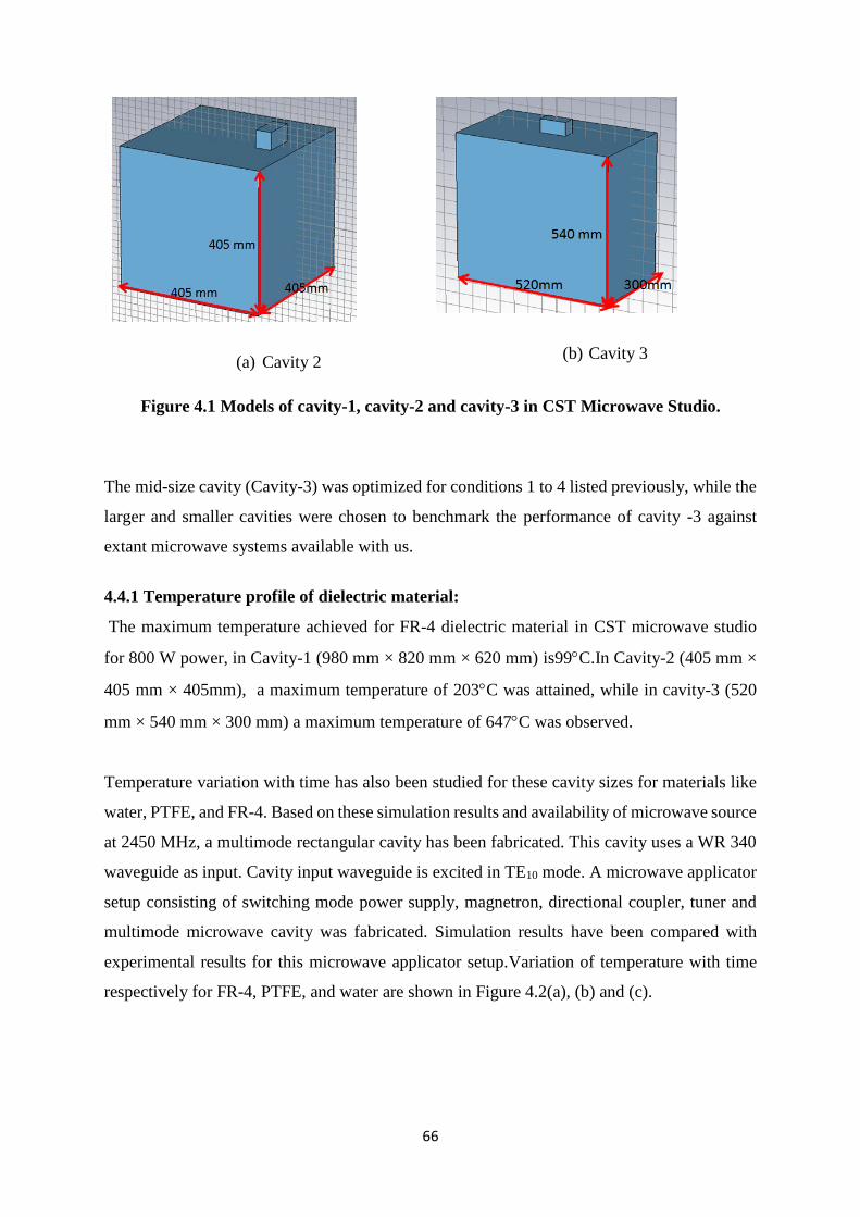
66
(a) Cavity 2
(b) Cavity 3
Figure 4.1 Models of cavity-1, cavity-2 and cavity-3 in CST Microwave Studio.
The mid-size cavity (Cavity-3) was optimized for conditions 1 to 4 listed previously, while the
larger and smaller cavities were chosen to benchmark the performance of cavity -3 against
extant microwave systems available with us.
4.4.1 Temperature profile of dielectric material:
The maximum temperature achieved for FR-4 dielectric material in CST microwave studio
for 800 W power, in Cavity-1 (980 mm × 820 mm × 620 mm) is99C.In Cavity-2 (405 mm ×
405 mm × 405mm), a maximum temperature of 203C was attained, while in cavity-3 (520
mm × 540 mm × 300 mm) a maximum temperature of 647C was observed.
Temperature variation with time has also been studied for these cavity sizes for materials like
water, PTFE, and FR-4. Based on these simulation results and availability of microwave source
at 2450 MHz, a multimode rectangular cavity has been fabricated. This cavity uses a WR 340
waveguide as input. Cavity input waveguide is excited in TE10 mode. A microwave applicator
setup consisting of switching mode power supply, magnetron, directional coupler, tuner and
multimode microwave cavity was fabricated. Simulation results have been compared with
experimental results for this microwave applicator setup.Variation of temperature with time
respectively for FR-4, PTFE, and water are shown in Figure 4.2(a), (b) and (c).

67
Figure 4.2 Variation of temperature with time for different cavities for (a) FR-4, (b)
PTFE and (c) Water.
These are temperatures recorded for maximum heating possible in a given cavity. As clearly
evident from the plots, maximum temperature for FR-4 is recorded in cavity-3, maximum
temperature for a PTFE load is obtained in cavity-2, while maximum temperature for water is
recorded in cavity-1.
As it is clear from figure 4.2 heating behavior of a microwave cavity is load dependent. For
different type of loads, due to their different dielectric characteristic and other parameters like
specific heat, density etc. microwave power coupling with the load is different; also for same
microwave power coupling heating behavior of material in terms of temperature can be
different. In case of water as shown in figure 4.2 (c), time scale is truncated as beyond 100ͦC
water is converted in vapour phase and due to phase mixing, results obtained from software

68
simulations will not be valid beyond this range. As it is clear from figure 4.2 (a), for FR-4
dielectric highest and fastest temperature rise is achieved in cavity 3, due to the best coupling
of microwave power with load. E-wastes constitute largely of FR-4, due to which cavity-3
seems to be an optimal choice for multimode cavity.
4.4.2 Electric Field Profile in Cavity:
Electric field profiles for all three cavities were analyzed in the presence of dielectric materials.
A dielectric block of size 80 mm × 60 mm × 40 mm was placed at the center of the cavity.
Dielectric material chosen was FR-4 and PTFE. FR-4 dielectric material was chosen due to its
ubiquity in Printed Circuit Boards (PCBs), while PTFE is a commonly used insulator. The
analysis confirms that a dielectric material exhibiting a higher electric field at its surface (or
“couples” better with the electric field in the cavity) heats up more rapidly. The electric field
at a dielectric surface is a function of input power, cavity structure and dielectric material
properties.

69
(a) Electric field profile with FR-4 in Cavity 1
(b) Electric field profile with FR-4 in Cavity 2
(c)Electric field profile with FR-4 in Cavity 3
Figure 4.3 Electric field profile in different cavities for FR-4

70
(a)Electric field profile with PTFE Cavity 1
(b)Electric field profile with PTFE Cavity 2
(c)Electric field profile with PTFE Cavity 3
Figure 4.4 Electric field profile in different cavities for PTFE

71
As it is clear from figure 4.3 and 4.4 standing wave patterns of electric field in a loaded cavity
vary with dielectric material properties. It is seen that cavity 3 records the highest intensity of
electric field for FR-4 dielectric, while for PTFE the highest field intensity is observed in
cavity-2. High intensity of electric field at dielectric surface indicates higher temperature will
be achieved while dielectric sample is exposed to microwave heating. This indicates that FR-4
will be subjected to the highest heating temperature in cavity-3, while this will be the case for
PTFE in cavity-2. This analysis again supports the suitability of cavity 3 for e-waste pyrolysis.
It may be mentioned here that we are only considering the electric field in view of the largely
non-magnetic nature of the load. Also, it is worth mentioning that in an unloaded cavity,
standing wave patterns (profile) of an electric field are formed depending upon the cavity
dimension and frequency of operation. These standing wave patterns (of electric field) are
distorted by the presence of a dielectric load. Depending upon the transparency of the load to
microwaves in the cavity, the standing wave pattern can be significantly modified. If the load
is transparent, such as PTFE (see Figure 4.4 c ), the standing wave pattern is largely retained.
However, in materials that are sparingly transparent such as FR4, the standing wave pattern is
smeared out significantly (see Figure 4.3 c).
4.4.3 Eigenmode Analysis:
Eigenmode analysis of all three cavities has been performed in CST microwave studio [81].
Eigenmode solver in CST microwave studio is used to calculate the resonant frequencies
without any excitation in an empty cavity. This solver can also be used for calculating the
electromagnetic field patterns corresponding to individual Eigenmodes. As compared to single
mode cavities, the multimode system provides uniform heating. Hence, a larger number of
modes correspond to more uniform heating of the dielectric material placed inside the cavity.
For cavity-1 within ± 5% frequency bandwidth more than 400 Eigenmodes are present. In
cavity-2, 81 Eigenmodes are present within the required frequency range, while in Cavity-3,
66 Eigenmodes are present within the required frequency range. Eigenmode analysis results
for cavity-2 and cavity-3 are shown in Figure 4.5.

72
(a)
(b)
Figure 4.5 Eigenmodes of (a) cavity-2 and (b) cavity-3.
The simulation results show that cavity-3, shows the best heating performance among the three
cavities modeled for FR4 as a load, while having an adequate number of Eigenmodes within
the required bandwidth.
4.4.4 Effect of Frequency:
Microwave heating can lead to non-uniform heating due to complex interaction of the
electromagnetic waves with a lossy material [65, 82]. Different factors that affect the heating
of dielectric in microwave cavities are shape and size of dielectric, location of dielectric,
dielectric properties, frequency of operation and microwave power. For this purpose, analysis
of frequency effects on FR4 dielectric for 3 different frequencies i.e. 2.4GHz, 2.45GHz and
2.5GHz have been performed. The power input for this analysis was 800W through a
waveguide feed in Cavity-3

73
4.6 (a)Power loss in dielectric at 2.4 GHz in cavity 3
4.6 (b) Power loss in dielectric at 2.45 GHz in cavity 3
(c) Power loss in dielectric at 2.5 GHz in cavity 3
Figure 4.6 Power loss in FR-4 dielectric as a function of frequency.

74
As is clear from figure 4.6, power loss density inside FR-4 dielectric sample varies with
frequency. Power loss density is represented in W/m3, frequency is chosen at 2.4 GHz, 2.45
GHz and 2.5 GHz. Frequency variations beyond this is not considered as microwave source
will not have a bandwidth out of this range. Out of these frequencies 2.45 GHz has highest
power loss density. Higher power loss density indicates higher amount of heat loss in dielectric
sample, which also indicates better heating performance in terms of temperature.
4.4.5 Feed Selection:
The operating frequency for the process was selected to be 2.45 GHz. A waveguide has been
chosen for the experiments. The upper and lower cut-off frequencies for this waveguide for
TE10 mode are 3.471 GHz and 1.736GHz. This is a rectangular waveguide with dimension 3.4
Inches [86.36 mm] × 1.7 Inches [43.18 mm].
4.4.6 Single Mode vs. Multimode Cavity:
After the comparison of three multimode cavities, cavity-3 was chosen, as maximum
temperature for FR-4 was achieved in this cavity. Now to compare the performance of this
multimode cavity with single mode cavity, a single mode cavity with a WR-340 waveguide
and length equivalent to this guide has been considered. Electric field profiles and temperature
profile comparison has been carried out for single mode cavity and multimode cavity with FR-
4 dielectric load placed within. As shown in Figure 4.7 maximum temperature achieved in a
multimode cavity is higher in comparison to single mode cavities. This comparison establishes
the superiority of multimode cavities for waste management, characterized by heterogeneous
loads.

75
Figure 4.7 Multimode vs Single Mode cavity performance with FR-4 load.
4.4.7 Reflection Coefficient Performance of Cavity-3:
Reflection coefficient represents the ratio of power reflected to the input power. Lesser
reflection coefficient indicates that more power will be absorbed in the load. Power absorbed
in the load is related to input power and reflection coefficient by the following relation:
𝑃𝑎𝑏𝑠 = 𝑃𝑖𝑛(1 − |𝑆11|2) … … …. (4.7)
where Pabs is power absorbed, Pin is the input power, and S11 is the reflection coefficient.
As shown in Figure 4.8, the reflection coefficient performance of cavity-3, with FR-4 dielectric
load is acceptable in the vicinity of the 2.45 GHz frequency range.

76
Figure 4.8 Reflection coefficient performance of cavity 3 with FR-4 load.
In figure 4.8 reflection coefficient performance of the cavity shows that cavity is having lower
reflections in the close range of source frequency 2.45 GHz, this shows that cavity is having a
good match in this frequency range. Multiple resonances in this frequency range indicate the
presence of multiple modes of cavity in this frequency region.
4.5 Analysis of Multimode Cavity for Nuclear Waste:
As per the analysis and modeling described above, cavity-3 was found suitable for heating of
electronic waste. Cavity-3 is now further analyzed for nuclear waste heating. In case of nuclear
waste heating, base dielectric is chosen to be a lithium borosilicate glass, which is the
encapsulating glass. Material which has to be encapsulated by the glass is Goethite. Heating
performance of Goethite and Lithium Borosilicate glass has been analyzed for maximum
temperature achieved and time vs. temperature behavior.
4.5.1 Heating of Lithium Borosilicate in Cavity-3:
Lithium borosilicate glass was modeled as the dielectric load in cavity-3. Properties of Lithium
Borosilicate were chosen as per the material used in actual experiments. Properties of Lithium
borosilicate used in simulations are listed below which are according to material used in actual
experiments for borosilicate glass:
1. Density = 2.66 g/cc

77
2. ε' @ 20oC = 8.01
3. tan δ = 5 ×10⁻³
4. Thermal conductivity = 0.45 W.m-1.K-1
5. Heat capacity of Lithium Borosilicate is a temperature dependent material property
which varies over temperature range. Temperature variation of heat capacity is listed in
table 4.1. Heat capacity has been defined as a nonlinear thermal property in multi
physics simulations for Lithium Borosilicate as per table 4.1.
Table 4.1: Temperature dependent heat capacity of Lithium Borosilicate glass
Temperature, oC Cp,J.kg-1.K-1
50 1033.4
100 1107.4
200 1229.5
300 1328.1
400 1410.8
450 1447.6
600 2116.5
700 2116.5
800 2116.5
900 2116.5
1000 2116.5

78
Figure 4.9 Heating of Lithium Borosilicate Glass Inside Cavity 3.
(a)
(b)
Figure 4.10 Temperature Profile of Lithium Borosilicate Glass Inside Cavity 3. (a) High
emissivity and (b) low emissivity.
Two scenarios of heating are modeled with the lithium borosilicate glass as shown in Figure
4.10 (a) and (b). In the first scenario, a high emissivity case is considered with emissivity of
0.95, which represents heating the glass without insulation. The second scenario represents a
low emissivity state, (emissivity of 0.05) representing the glass melting in an insulated
e=0.05
e=0.95

79
enclosure. This simulation highlights the necessity to minimize emissivity during melting since
the maximum temperature attained in the high emissivity case is ~ 600oC, which is insufficient
to melt the glass. However, if the glass is suitably insulated, then temperatures approaching
1400oC can be reached, which is well above the melting temperature of the glass used. These
results are shown in Figure 4.9. Temperature profile of lithium borosilicate glass is shown in
Figure 4.10. In appendix 2 comparison of dielectric properties of borosilicate glass with other
dielectrics has been given.
4.5.2 Heating of Goethite:
Figure 4.11 Heating of Goethite inside Cavity 3.
e=0.05
e=0.95

80
(a) High Emissivity (e=0.95)
(b) Low Emissivity (e=0.05)
Figure 4.12 Temperature Profile of Goethite Inside Cavity 3.
Since glass is designed to encapsulate Goethite, simulations were also performed using goethite
as a load for low (emissivity = 0.05) and high emissivity (emissivity = 0.95) cases. The
maximum temperatures attained in both cases were approximately 450oC and 1150oC. The
temperature versus time curve and the temperature distribution is presented in Figures 4.11 and
4.12.
From the simulation results for Goethite and Lithium Borosilicate Glass, it is clear that heating
of borosilicate glass results in melting of glass. However, the temperatures encountered are
lower than the melting point of goethite, which indicates that with a sufficiently rapid heating
and cooling rate, it may be possible to encapsulate the goethite corrosion product in a glass,
without the corrosion product dissolving in the glass. The validity of these studies in Cavity-3
indicates the suitability of Cavity-3 for 99Tc management as discussed subsequently.
4.6 Summary
Based on the heating temperature achieved for FR-4 dielectric placed inside the cavity at the
centre, cavity-3 was chosen for microwave applicator design. Performance of all 3 cavities has
been compared for heating temperature and electric field distribution within the cavity. It is
seen that cavity performance is a function of load and frequency of operation.
Performance of cavity-3 has been analyzed with variation in frequency for FR-4 load. Also,
the performance of cavity 3 is compared against a single mode cavity and it is found that higher

81
heating temperature is achieved in a multimode cavity. Reflection coefficient performance of
cavity-3 is also found to be satisfactory at frequency of operation of 2.45 GHz.
The performance of cavity-3 for nuclear waste immobilization using lithium borosilicate for
fixation of goethite was evaluated. The simulations show clearly that insulation allows higher
temperature to be reached where the glass will melt and encapsulate the goethite corrosion
product.

82
Chapter 5
EXPERIMENTAL CASE STUDIES: E-WASTE
MANAGEMENT
The previous chapters have dealt with numerical modeling in optimizing the performance of
microwave cavities for specific purposes. In this chapter, results of specific case studies in
terms of e-waste are discussed. These studies demonstrate the effectiveness of microwave
processing in e-waste management.
The chapter is broadly organized into two sections. The first section is devoted to e-waste
management using microwave heating systems, while in the second section treatment of e-
waste using other heating techniques is described. This section also covers numerical and
mathematical analysis carried out for e-waste management using resistance and induction
heating systems for a broad comparison. Various experiments carried out on e-waste processing
are duly covered in both the sections. As discussed in the literature survey, e-wastes,
particularly in developing countries constitute a growing human and environmental hazard. An
efficient process to allow rapid volume reduction with minimal secondary waste generation is
the need of the hour. Such a process can also be dovetailed into suitable recovery for precious
metals, making the processing of e-waste more economically attractive [3].
5.1 e-Waste Management:
e-waste constituting end-of-life electronic components is highly heterogeneous, but at the same
time contains precious metals that can be recycled [8]. The first goal is therefore volume
reduction, followed by removal of volatile organic compounds before consolidation for
possible recovery [3]. Literature studies have identified pyrolysis for volume reduction as an
important step in the management of e-wastes. However, most of the processes discussed both
in literature and adopted for actual waste management, eschew microwave processing and rely
upon resistive or induction heating. Therefore, a comparison of microwave heating with
conventional resistive and inductive heating techniques is presented. This section will also help
highlight the advantages of microwave processing versus conventional techniques.

83
5.1.1 Thermal Analysis of e-wastes:
The first step in the management of e-waste involves heating the waste using resistive,
inductive or microwave techniques. Therefore, it is imperative to understand the effect of
heating on e-wastes using thermal analysis techniques allied to evolved gas analysis. A
Differential Thermal Analysis (DTA) equipment was used for measuring the heat flow into or
out of the sample with respect to an inert reference material. Mass change as a function of
temperature was recorded using a thermo-gravimetry (TG) measurement balance built into the
DTA equipment. In order to ensure reproducibility, the experiments were carried out on two
separate batches of e-waste. In each case, the representative e-waste sample was crushed into
small pieces, taken in a platinum crucible and heated in the range of 25 – 1000oC at a rate of
10°C.min-1 under air background. These experiments were used as a baseline for pyrolysis and
interaction of the sample with air under heating. The change in mass and the heat flux were
recorded as a function of temperature during the above analysis. The TG-DTA plots of the two
batches are presented in Figure 5.1 showing variation of Mass loss and heat flow with
temperature for representative e-waste samples. The heat flow is represented with temperature
difference in the plot, as the rate of heat loss or flow is directly proportional to the temperature
difference.
Figure 5.1 TG-DTA plots of two batches of representative e-waste samples.

84
The mass loss results for both batches are collated in Table 5.1
Table 5.1: Mass loss results for both batches of e-waste
Sample Step-1 Step-II Total
Mass
loss
(%)
Temperature
range
(°C)
% mass
loss
Temperature
range (°C)
% mass
loss
e-waste (Batch -1) 260-350 °C 09.50 350-550°C 7.10 16.60
e-waste (Batch- 2) 260-350 °C 12.21 350-550°C 6.64 18.85
In both the cases a two-step mass loss was observed in the temperature range of 260o-350o and
350-550°C with a total loss of 16.6 and 18.85 %. The mass loss was found to be 9.5 and 12.21%
in the first step and 7.1 and 6.64 % in the second step. Studies were further extended to
understand the gaseous products generated during heating of e-waste up to 700°C under the
flow of Argon gas using a TG-DTA with attached Evolved Gas Analysis (EGA). The mass
spectrum emerging from EGA reveals peaks in the mass range of 12-136. The intensity of these
peaks has been plotted as a function of temperature in Figure 5.2. The observed peak for the
mass number 40 in the temperature range 290-430°C could be due to the decomposition of
Propane. The other intense peak at masses 17, 18, 28 and 44 could be due to H2O, CO, CO2,
respectively [4]. These are the possible combustion products of hydrocarbons. Most of the mass
peaks arising in the mass spectrum are hydrocarbon combustion products.

85
Figure 5.2 TG-MS plot for e-wastes.
TG-DTA and evolved gas analysis was also employed to understand the role played by the
environmental gas during heating. These studies were carried out by heating the sample under
inert gas environment.These studies were motivated by the fact that heating under inert gas can
be avoided to the extent possible for ease of implementation. We found that gas evolution was
not significantly altered in air environment. The TG curves are presented in Figure 5.3. The
black trace represents heating in air, while the purple curve represents heating under inert gas
(N2). In both air and inert gas environments, mass loss begins at 270oC with 28% and 29%
mass loss observed in inert and air atmospheres respectively.

86
Figure 5.3 TG curves in air (black) and N2 (purple).
The only significant difference between air and inert environment processing is that in case of
heating in air, mass loss is complete by on attaining temperature of around 500oC, whereas in
case of the inert gas environment, mass loss continues till the temperature of 900oC. This
behaviour seems to suggest that in an air environment, oxidative processes ensure rapid
removal of carbonaceous residues. As a result, the DTA curves shown in Figure 5.4 show a
pronounced exothermic event in samples heated under air. While the position of the exotherm
is largely unchanged under heating in an inert environment, its intensity is diminished. Further,
in samples heated under air atmosphere, an exotherm is evident at ~ 680oC, which is not present
in samples heated in an inert environment. This exotherm is attributed to the oxidation of metal
oxides from the PCBs.
However, the similarity of mass loss in both scenarios indicates that the effect of the
environment in overall mass loss seems insignificant.

87
Figure 5.4 DTA curves of e-waste in air (blue curve) and in N2 (brown curve).
A Gram-Schmidt curve for e-waste heated in air and N2 is presented in Figure 5.5. The
decomposition of the e-waste residues takes place in four steps evident by the four peaks in the
Gram-Schmidt curves.
Figure 5.5 Gram-Schmidt curves for e-waste in air (brown curve) and N2 (black curve).
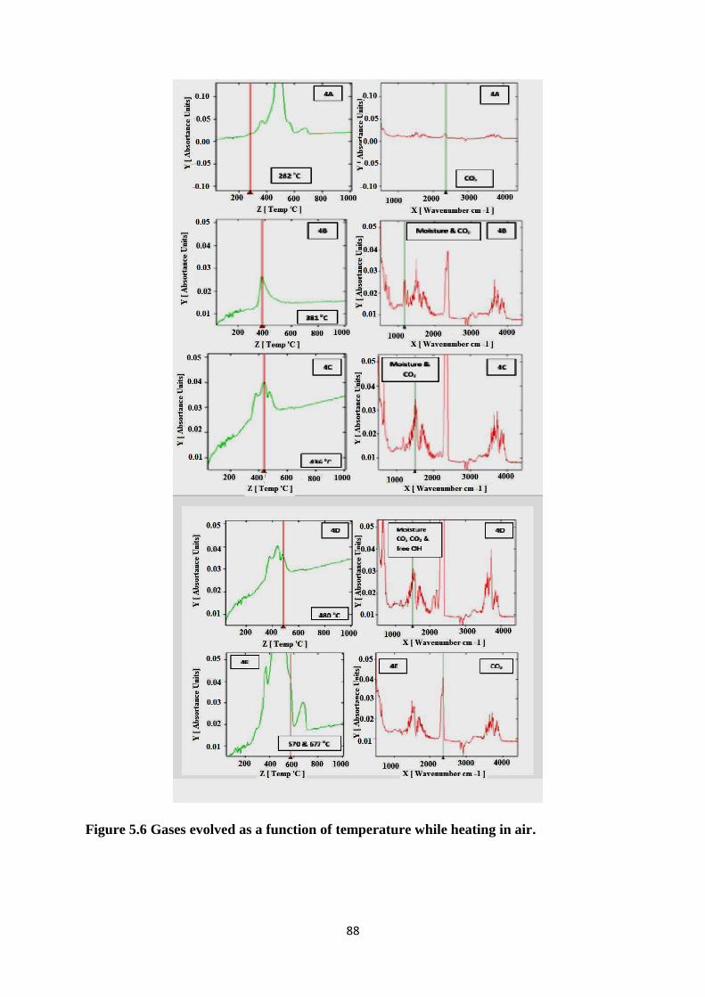
88
Figure 5.6 Gases evolved as a function of temperature while heating in air.

89
The gas evolution studies in air as a function of temperature are presented in Figure5.6.Similar
gas analysis for e-waste samples heated under an inert environment is presented in Figure 5.7.
Figure 5.7 Gases evolved as a function of temperature while heating under inert
environment.

90
By comparing both the cases, it is observed that in case of air, gas evolution begins at 282oC
with the release of CO2, while a combination of unidentified gases were released during heating
under inert gas. This gas characterized by strong absorbances at 750, 1154, 1261 and 3643 cm-
1, which can be attributed to the evolution of alcohols, with the 1154 cm-1 and 1261 cm-1
absorbances assigned to C – O stretching mode and the 3643 cm-1 assigned to O – H stretching
mode [83]. The absorbance at 750 cm-1 is likely an alkyl halide [83]. The overall gas release
profile is the same for both environments, except for CO formation in samples heated in air.
The mass spectra of the evolved gases confirms as shown in Figure 5.8 the evolution of CO2,
acetylene, acetone and oxetane [83].
Figure 5.8 Mass spectra of (top to bottom) CO2, acetylene, acetone and oxetane. The
respective retention times in minutes are: 2.35, 4.13, 2.15 and 8.45.

91
These experiments suggest that heating is possible in both inert and air environments to achieve
similar mass loss. The PCB residue obtained after pyrolysis was analyzed using XRD. The
diffractogram is presented in Figure 5.9.
Figure 5.9 X-ray diffractogram of PCB residues post pyrolysis in DTA. The
crystalline peaks correspond to TiO2, SnO2 and Al2O3.
5.1.2 Heating Experiments:
Based upon the confidence gained from the previous studies, a series of lab scale studies were
planned using resistive, inductive and microwave heating to compare the performance of these
techniques.
5.1.2.1 Resistive Heating:
As the name suggests, resistive heating involves heating the sample by radiant heat from
resistance heating elements in an electric furnace in which the heat is developed by the passage
of electric current through a Nichrome made heating element. The furnace is made of with high
temperature refractory materials to prevent heat loss and the temperature is controlled by
controlling the flow of electric current through the element.
The experiments were carried out by heating weighed, crushed PCB samples in resistance
furnaces. The samples were contained in a quartz bell jar and off-gas treatment was provided.
A combination of different sample masses, heating rates and times were experimented. All
heating rates and temperatures were set using a PID controller. A thermocouple was mounted

92
inside the mass of crushed PCBs to monitor the temperature. The block diagram of the furnace
used in the experiment is shown in Figure 5.10. A file photograph of the experimental setup
used for this study is shown in Figure 5.11.
Figure 5.10 Block Diagram of Resistance heating Furnace
(SSR represents Solid State Relay)
Figure 5.11 Actual experimental set-up with twin scrubber arrangement.
5.1.2.2 Inductive Heating:
Induction heating takes place in an electrically conducting object when the object is placed in
a varying magnetic field. Induction heating is due to the hysteresis and eddy-current losses.

93
Induction heating is the cleanest, efficient, cost-effective, precise, and repeatable method of
heating. In induction heating setup a high frequency inverter supplies an AC current to a copper
coil acts as an inductor and the part to be heated (the workpiece) is placed inside the inductor.
The inductor serves as the transformer primary and the conducting material to be heated
becomes a short circuit secondary. Circulating eddy currents are induced within the conducting
material when alternating current is flowing through the coil. These eddy currents are flow
against the electrical resistivity of the material, generating precise and localized heat without
any direct contact between the material and the inductor.
Figure 5.12 Schematic of induction heating set-up.
Figure 5.13 Induction heating furnace with twin scrubber
A schematic diagram of the inductive heating set-up is presented in Figure 5.12. Since most
circuit board materials are insulators and do not develop eddy currents, the PCB pieces are

94
taken in a graphite crucible, which couples to the induction coil and subsequently heats the
material in the crucible. A file photo of the experimental set-up for the same is presented in
Figure 5.13.
5.1.2.3 Microwave Heating:
A schematic diagram of a microwave furnace and a file photograph of the actual set-up used
are presented in Figures 5.14 and 5.15 respectively. The furnace was provided with two
scrubbers to analyze residues formed during the pyrolysis process. All the processes described
in this section and those involving resistive and inductive heating were performed in air.
Figure 5.14 Schematic view of microwave furnace.
Figure 6 File photograph of the microwave furnace used with integral dual scrubbers.

95
5.1.3 Comparative Analysis of Heating Techniques:
Based upon the experimental set-ups described in the previous section, the efficiency of all
techniques was compared in terms of temperature attained, time to temperature and mass loss
for a known quantity (5 g) of e-waste. Table 5.2 collates the results of these studies. Also
presented in Table 5.2 is the analysis of the scrubber residues for all three experiments.
Table 5.2: Comparison of heating in resistance, induction and microwave, with
elemental analysis in the scrubber
Technique
Parameters
Value
Resistance Induction Microwave
Scale 5 g 5 g 5 g
Temperature, C 415 415 350
Weight loss, % 19.45 22.93 25.1
Time, Minutes 25-35 25-35 5-6 min
Temperature, C 600 600 600
Weight loss, % 3.40 6.50 1.2
Time, Minutes 15-20 15-20 6-7 min
Cumulated weight loss, % 22.8 29.43 26.30

96
Table 5.2 (Contd.): Comparison of heating in resistance, induction and microwave,
with elemental analysis in the scrubber
Elemental concentration in
scrubber (200 ml each) mg/L
Scrubber
(Resistance)
Scrubber
(Induction)
Scrubber
(Microwave)
Elements Water 1 2 1 2 1 2
B 0.167 1.66 0.106 0.57 0.67 0.137 0.0968
Si 0.61 47.1 10.8 22.8 10.9 2.26 1.838
Cu ND 0.048 0.021 0.04 0.05 11.7 7.73
Ca ND 13.2 11.0 9.48 8.68 0.867 0.633
Zn ND 1.14 0.321 0.32 0.03 0.021 0.01
Al ND BDL BDL BDL BDL BDL BDL
In Table 5.2, 1 and 2 denote the first and second scrubber. Overall, B, Si and Zn are released
in smaller quantities in case of microwave heating compared to the other two techniques, while
Cu is higher. Microwave heating is fastest among all three techniques as per comparison given
in table 5.2. We anticipate that the Cu could be released due to the formation of plasma hot
spots on connectors and conducting elements made of Cu. The violent sparking could then
cause ejection of fine metal spall, which is then collected in the scrubbers [84]. Overall, the
performance of all the heating techniques was comparable. However, the time required for
microwave heating was much lower allowing higher process efficiency.
5.1.4 Comparison of heating in inert environment in resistance and microwavefurnaces:
The previous heating studies were carried out in air, and the rapid processing enabled by
microwave heating was found advantageous. Based upon this, a further study was conducted

97
to analyze the effect of brominated compounds in PCBs and their potential volatility under
treatment. In keeping with earlier findings, these studies were carried out under an inert
environment (N2). The goal of these studies was to evaluate the retention of environmentally
hazardous compounds post processing. Toward this, SEM and EDS studies were carried out
on pristine PCBs. These are reported in Figure 5.16. The PCBs exhibit high concentration of
Pb and Sn (both common solder and interconnect materials) [1, 2]. This finding highlights the
potential hazard of direct landfilling shredded PCB residues as these elements can leach from
the landfill and contaminate soil and water (both surface and subsurface).
The PCB residues were then heated under N2 to about 390oC for resistive heating and about
350oC for microwave heated samples. The elemental composition of these residues is also
presented in Figures 5.17 and 5.18 respectively.

98
Figure 5.16 SEM and EDS spectra of pristine PCB boards (refer text for details)

99
Figure 5.17 SEM and EDS spectra of PCB residues heated at390oC in a resistive
furnace in N2

100
Figure 5.18 SEM and EDS spectra of PCB residues heated in microwave furnace at
350oC in N2 (see text for details).

101
As evident from EDS presented, upon processing in a resistive furnace, Pb is not evident in the
spectra, while in the case of microwave processed systems, Cu, Zn, Pb and Br are retained in
the residue. The retention of Cu, Zn and Pb is likely caused by the formation of alloys under
high temperature plasma hot spots generated during microwave processing [3]. Consequently,
these materials are retained in the residue during microwave processing.
From the above three different type of different heating technique, it is found that microwave
technique is the best for processing of e-waste with respect to processing time, efficiency and
less hazardous flow gas generation.
5.2 Analytical and numerical analysis using conventional heating methods
As for sake of completeness, analytical studies carried out using conventional heating methods
for e waste treatment are presented herewith in brief. For preliminary analysis, 5 g of E-waste
samples were considered. Based on sample size, power required to achieve desired
temperature, i.e, 400oC and 600oC in 15 min is estimated by analytical method and results were
compared with numerical method.
5.2.1 Resistance heating
For resistance heating of E-waste, a muffle furnace is used; in which heat is indirectly
transferred from heating elements to E-waste. Total energy required to raise the temperature of
E-waste includes heat energy absorbed by E-waste, heating elements, refractory and heat loss
by conduction, convection and radiation. These data can be estimated by doing heat transfer
analysis [9]. Schematic of resistance heating is shown in Figure 5.19.
Thermocouple
Electric Heater
Refractory
E-Waste
Figure 5.19 Schematic of resistance heating method used for pyrolysis

102
For resistance heating, a pit type furnace of dimension 300 mm (H) × 300 mm (W) × 300 mm
(H) having working chamber size of 50 mm (dia.) has been considered based on sample size.
Heat energy was estimated for nichrome heating elements and ceramic fibre board refractory
[11]. PCB material composition and corresponding melting points are given in Table 5.3.
Materials properties such as electrical conductivity, thermal conductivity, specific heat and
density were taken at temperature of 300o C as shown in Table 5.4. Physical properties such as
density, specific heat were estimated by using bulk density and bulk specific heat formulations.
Thermal and electrical conductivities of PCB E-waste were estimated by using equivalent
thermal resistance and electrical resistance. Equivalent physical properties of E-waste powder
are shown in Table 5.4. As per heat transfer analysis, total power required to raise the
temperature of E-waste to 400o C and 600o C in 15 min is 2223 W and 2985 W respectively.
Table 5.3: Material Composition of PCB E-waste [11]
Table 5.4: Physical properties of PCB E-waste [11]
Numerical analysis of resistance heating has been carried out by using FEM based multi
physics software. Geometry shown in Figure 5.20 and material properties given in Table 5.4

103
were used for simulation. Tetrahedral mesh elements were used for domain discretization as
shown in Figure5.21. Boundary heat flux was used as forcing function according to analytically
estimated power.
Figure 5.20 Geometry for numerical analysis of resistance heating technique; 3D
Geometry of E-waste sample.
Figure 5.21 Domain discretization for numerical analysis of resistance heating
technique; Solution domain discretization using tetrahedral mesh elements.

104
Figure 5.22 Temperature profile in E-waste sample by resistance heating technique For
4000C.
Results obtained by numerical analysis are shown in Figure 5.22 and Figure 5.23 for 4000C
and 6000C respectively. It is observed that analytical and numerical results are very much close
to each other and average error is of the order of 5 %.
5.2.2 Induction heating
Induction heating technique is based on Faraday’s Law of electromagnetic induction.
According to it, when any conducting material is placed in varying magnetic fields then eddy
current is induced into it and that will heat the material by Joule’s effect [9]. As it is well
known, 72 % of PCB E-waste material is FR4, which has very low electrical conductivity and
also the shape of the E-waste sample is non-uniform, which makes it difficult to heat it by
direct induction heating technique. Hence PCB E-waste is heated by indirect induction heating
technique in which, a susceptor is used that couples with electromagnetic fields and heats up
the PCB E-waste indirectly by conduction, convection and radiation. Total input power is
estimated based on power absorbed in crucible and E-waste and considering thermal and
electrical efficiencies. Schematic of induction heating is shown in Figure5.24.
Figure 5.23 Temperature profile in E-waste sample by resistance heating
technique for 6000C.

105
Figure 5.24 Schematic of induction heating method used for pyrolysis.
In induction heating, graphite crucible was considered as per dimensions given in Table 5.5.
Crucible wall thickness is selected based on skin effect criteria considering the frequency of
power source. Generally, a refractory is placed between coil and crucible to protect the coil
from crucible heat and improve the heating efficiency. Physical properties of graphite and
refractory were taken from [10-12] for analytical and numerical analysis. Total power required
to achieve 4000C and 6000C temperatures for E-waste in 15 min was 353 W and 521 W
respectively; which was estimated based on heat energy absorbed by graphite crucible, 5g E-
waste, refractory and also by considering thermal losses. According to work piece power and
crucible capacity; coil dimensions such as coil diameter, coil height, number of turns, coil
current etc. were estimated and detail of the same is given in Table 5.6. Coil equivalent
parameters were used to estimate the coil efficiency and input power, which were 85% and 416
W and 613 W for 4000C and 6000C respectively.

106
Table 5.5: Graphite crucible dimension andproperties
Table 5.6: Induction coil dimensions and properties
Work Piece Description
Material Graphite
Outer Diameter(mm) 80
Wall thickness, th(mm) 10
Height(mm) 85
Electrical Conductivity(S/m) at 3030K 1.458×10⁵
Electric permittivity 1
Magnetic permeability 1
Density(kg/m3) 8700
As per analytical investigation, 2-D Axi-symmetric geometries of coil, crucible and refractory
were prepared as shown in the Figure 5.25. Triangular mesh elements were used to discretize
the solution domain by considering the physics phenomena as shown in Figure 5.26. Graphite
and copper properties given in the [10] were used for simulation.
Induction coil Description
Material Copper
Inside diameter(mm) 100
Outside diameter(mm) 124
Height(mm) 100
Coil tube diameter (mm) 12
Coil tube thickness(mm) 1
Number of turns 7
Electrical conductivity(S/m)
at 3030K
5.950×10⁷
Electric permittivity 1
Magnetic permeability 1
Density(kg/m3) 1736

107
Figure 5.26 Domain discretization using triangular mesh element for numerical analysis
of induction heating technique.
Electromagnetism and heat transfer have been analyzed in frequency domain and transient
domain due to the difference in time scale of both the physics. Boundary conditions for
electromagnetism and heat transfer are shown in the Table 5.7 and 5.8 respectively.
Table 5.7: Boundary condition and forcing function for electromagnetism [10]
Sr.No. Boundary condition Description
1. Outer boundary A=0
2. Axi- symmetry axis 𝜕𝐴
𝜕𝑛= 0
3. Coil current 60A, for 400̊ C
73A, for 600̊C
Figure 5.25 2-D axisymmetric geometry for numerical analysis of induction
heating technique.

108
Table 5.8: Initial and boundary condition for Heat transfer [10]
Sr.No. Boundary condition Description
1. Initial temperature 303K
2. Convection coefficient(h) 10 (W/m2K)
3. Emissivity ( Graphite surface) 0.90
4. Emissivity (Refractory surface) 0.54
Figure 5.27 Temperature profile in E-waste sample by induction heating
technique For 4000C.

109
Simulation results for 4000C and 6000C are shown in the Figure 5.27 and Fig 5.28.
From above figures, it is observed that analytically and numerically obtained results are in
good agreement and error is less than 7 %. These results encouraged authors to implement
numerical models to validate the experimental data during this study.
5.2.3 Experimental set up and test parameters:
To validate theoretical data, resistance heating and induction heating of E-waste have been
carried out. The PCBs were broken and cut with metal cutters. Adequate amounts of samples
were cut into very small pieces and taken for testing as per the standard procedures to subject
the same for the heat treatment process using different techniques. Accurately weighed, 5 g of
representative E-waste samples were taken and heated in laboratory scale pit furnace and
induction heating furnace with two water scrubber units in series along with suitable vacuum
pump.
Resistance heating furnace of capacity 3.5 kW and induction heating power source of 5 kW,10-
20 kHz have been used. As per analysis, E-waste sample was heated up to 4000C and after 30
min. of soaking period, weight of E- waste sample was measured at room temperature (of the
order of 300C). In the second step, the E-waste sample was again heated up to 6000C from
room temperature and after 15 min of soaking period, the weight of E-waste sample was again
measured at room temperature (of the order of 300C).
During the resistance and induction heating experiment, approximately25min and 15min
duration were required to achieve 4000C and 6000C temperatures respectively whereas in case
Figure 5.28 Temperature profile in E-waste sample by induction heating technique
For 6000C.

110
of microwave heating, same temperatures were achieved in approximately 05min and 06min
respectively.
During the induction heating experiment, coil current and crucible temperature were measured
by using Rogowski coil and multiwave length pyrometer respectively. Coil current (i.e., 1.14V
is equivalent to 114 A) shown in Figure5.29 was used as a forcing function for numerical
analysis.
Figure 5.29 Coil current measured during experiment
Numerically obtained crucible temperature profiles based on experimental parameters
for 4000C and 6000C temperatures are shown in Figures 5.30 and 5.31 respectively and these
data were validated with experimentally observed crucible temperatures as shown in Figure
5.32.

111
Pyrometers used for temperature measurement have temperature ranges from 3750C to
11500C. Therefore, temperature data below 3750C was obtained by fitting a polynomial of
second order to the data. The numerical, experimental and fit data are plotted as shown in
Figure 5.32. From this figure, it is observed that numerical and experimental results are in
good agreement and maximum error is less than 15%.
Figure 5.30 Temperature profile in E-waste sample by
induction heating technique For 4000C.
Figure 5.31 Temperature profile in E-waste sample by
induction heating technique For 6000C.

112
Results of the heating experiments in terms of weight reduction of E-waste by resistance,
induction and microwave heating techniques are shown in Table 5.9.
Table 5.9 Comparative parameters and outcome of the experimental studies
Parameters Resistance heating Induction heating Microwave Heating
Scale 5 g 5 g 5 g
Temperature, ̊C 400 400 350
Soaking period,
min
25-35 25-35 5 - 6
Weight loss, %
19.45 22.93 25.1
Temperature, ̊C1
600 600 600
Soaking period, min.
15-20 15-20 6-7
Weight loss, %
3.40 6.50 1.2
Cumulated weight loss
22.8 29.43 26.30
From Table 5.9, it is observed that weight reduction of E-waste in resistance heating
technique is 22.8 % while in induction heating it is 29.43 %. Induction heatingwhile
comparing with resistance heating technique is relatively efficient and fast. However,
Figure 5.32 Numerical and experimental validation of
crucible temperature in induction heating

113
microwave heating is comparatively much more efficient than both these conventional
techniques. In microwave heating system, the weight loss percentage is about 26.50, while
the processing time is 12 minutes compared to 45 minutes in resistance and induction heating.
5.3 Summary:
The studies highlighted above show that microwave processing is more efficient and allows
rapid pyrolysis of e-waste residues. The studies also highlight the importance of e-waste
processing since untreated e-waste contains significant concentration of Pb, which is a known
environmental hazard.

114
Chapter 6
EXPERIMENTAL CASE STUDIES: NUCLEAR
WASTE MANAGEMENT (99Tc)
This chapter is broadly devoted to nuclear waste management using microwave heating
systems, particularly; Technetium (99Tc) immobilization. As discussed in the literature survey,
microwave systems can be effectively deployed in Nu-wastes processing for rapid volume
reduction with minimum environmental hazard. An efficient process can also be dovetailed
into vitrification of long lived radioactive waste elements, making the treatment of nu-waste
industrially viable [3].
In terms of nuclear waste, this thesis focuses on a possible methodology for 99Tc management
by consolidation of 99Tcbearing mineral phases (corrosion product of ferrous steel) in a suitable
glassy matrix. The objective of these studies is to encapsulate the 99Tc bearing mineral phase,
while preventing their dissolution in the glass, to minimize remobilization risks.
6.1 Technetium (99Tc) Management:
As discussed in the literature review, Technetium (99Tc) is a potentially challenging
radionuclide combining high fission yield and a long half-life [17, 18, 49]. In its oxidized
pertechnetate form, Technetium (99Tc) in its +7 oxidation state, 99Tc(VII), is highly geo-
mobile, adding to immobilization concerns. At the same time, high temperature processes such
as direct vitrification are unsuited to 99Tcimmobilization due to volatility concerns. In this
work, we describe a potential process to immobilize99Tcbearing Fe corrosion residues using
microwave assisted processing.
6.1.1 Reductive Mineralization of Tc:
A novel technique for the immobilization of 99Tcis reductive mineralization in Fe corrosion
products such as Goethite. Fe is one of the most ubiquitous elements in the earth’s crust.
Depending upon oxygen availability, Fe may occur either as Fe2+ or Fe3+, and the Fe2+/Fe3+
REDOX pair is important for the immobilization of various contaminants such as As, U,
etc.[85, 86]. This is particularly true for high surface area iron oxyhydroxides such as
Ferrihydrite that act as natural sinks for many heavy metals.

115
Further, in case of species such as 99Tc(VII), reduction to +4 oxidation state, 99Tc(IV),
accompanied by an oxidation of Fe2+ to Fe3+ is a prelude to mineralization in either Goethite
or Magnetite phases [18]. Figure 6.1 depicts a schematic of reductive immobilization of Tc in
Goethite. Indeed, such uptake in a mineral phase reduces the oxidative remobilization risk
associated with Tc.
However, the Tc bearing goethite powder can be scattered easily and must be consolidated in
a suitable waste form to prevent dispersal. In this work, we demonstrate the use of microwave
heating to consolidate the goethite using a Li-borosilicate glass. The choice of glass is
motivated by the strong coupling of the Li+ ions with the electromagnetic field generated in the
glass by the microwave radiation.
6.1.2 Experimental Case Studies:
The case study in the present case is the consolidation of technetium bearing goethite, however
since actual active trials will require specially designed shielded facilities and characterization
access will be limited. Demonstration trials have been carried out using inert goethite. It may
Figure 6.1 Schematic of Tc (IV) replacing Fe (III) in the lattice of Goethite
accompanied by the expulsion of H+ for charge neutrality [18].

116
be mentioned that Technetium uptake in goethite does not alter the crystallographic or chemical
properties of goethite. Therefore, the consolidation trials p-resented are a faithful surrogate to
the actual case study involving active (99Tc) containing samples. Microwave heating and
resistive heating are the main techniques used here for this case study.
Microwave Heating Systems:
Microwave heating experiment was carried out using commercially available microwave oven
(with oven cavity dimensions as 306mm (H) x 306.6mm (W) x 208.2mm (D) and 800W rated
microwave power output ). The experiments were performed under the fume hood where a
temperature controller with K type thermocouple and display unit was attached to the
microwave oven to measure the inside temperature. Also, a vacuum pump (10 LPM) was used
for evolved gas scrubbing and gaseous sample collection. The overall set up has shown as
Figure 6.2. The gas samples collected during microwave heating of sample were analyzed
using Gas Chromatography.
Figure 6.2 (a) Microwave Heating Setup in fumehood
Figure 6.2 (b) Schematic of Microwave assisted melting of glass

117
Figure 6.2 (c) Cross-section of sillimanite crucible after melting
Resistive Heating Systems:
In resistance heating of e waste, heat is indirectly transferred from heating element to nu-
waste. Total energy required to raise the temperature of nu-waste includes heat energy
absorbed by nu-waste, heating elements, refractory and heat loss by conduction, convection
and radiation. In our case, a muffle furnace is used in which a crucible is kept with glass,
goethite (99Tc) place inside it. The glass beads were melted in the ceramic crucible by putting
in the electric furnace. The glass level was maintained up to 95% of the crucible height. It
takes three to four batch operations for preparing theactual amount of glass. Resistivity
measurement technique is explained in Appendix 1.
Figure 6.3 (a) Crucible

118
Figure 6.3(b) Crucible at the time of removal from surface
6.1.3 Consolidation Trials:
Consolidation trials were carried out using both resistive and microwave assisted heating
techniques. The compositions selected for these trials are presented in Table 6.1. In it, the base
composition represents the parent glass with no corrosion product added.G10, G20, G30 and
G40 represent waste compositions with 10, 20, 30 and 40 wt. % of corrosion product added.
The glasses were mixed with known quantities of corrosion product and treated either in a
resistive furnace (suffix – F) or in a microwave furnace (suffix – MW). The glasses obtained
were characterized using XRD, Raman Spectroscopy and TG-DSC. Chemical durability of the
waste forms was analyzed using standard leach tests according to ASTM C1220-17 [87]. The
leaching properties of both microwave and furnace melted samples were similar as shown in
Table 6.2.

119
Table 6.1: Compositions of the glasses prepared
Oxides Base G10 G20 G30 G40
SiO2 38.8 34.92 31.04 27.16 23.28
B2O3 24.44 22.00 19.55 17.11 14.66
Na2O 16.66 14.99 13.33 11.66 10.00
TiO2 5.55 5.00 4.44 3.89 3.33
CaO 5.55 5.00 4.44 3.89 3.33
Li2O 8.88 7.99 7.10 6.22 5.33
Corrosion Product 10 20 30 40
For the laboratory scale studies, a microwave cavity as modeled in Chapter 4, was used. Glass
frit, mixed with a suitable quantity of goethite was taken in a sillimanite crucible, which was
placed in an insulated cavity in the microwave furnace. The insulation ensured that radiation
losses were minimal, allowing glass melting. Typically, glass melting in the microwave
required 10 minutes. After homogenization for a further 20 minutes, the glass obtained was
poured out.

120
Table 6.2: Normalized Fe leach rates for glasses prepared in a
furnace (F) and in a microwave melter (MW) in (g.cm-2.day)
G10 20% 30% 40%
F (g.cm-2.day) BDL BDL 7.73×10⁻⁷ 8.27×10⁻⁷
MW (g.cm-2.day) BDL BDL 6.23×10⁻⁷ 9.27×10⁻⁷
Figure 6.4 Variation in Tg with loading of Fe-corrosion product.
From the variation of Tg with loading depicted in Fig. 6.4, it is observed that the glass transition
temperature of the furnace processed glass increases till about 20 wt% loading, while
subsequent increase in the Tg is comparatively slow. However, in case of the microwave melted
glasses, the increase in Tg is gradual compared to the furnace melted samples. This seems to
indicate that a smaller quantity of Fe enters the glass network in case of microwave melting.
Indeed, the formation of Fe3+ – O – Si linkages in the microwave melted glass could be
responsible for the increase in Tg [88]. The variation in Tg suggests that under furnace melting,

121
the crystalline phase dissolves in the consolidating glass, which also means that the 99Tc
bearing mineral phase is likely to dissolve into the glass with attendant risk of
remobilization/evaporation of 99Tc. In comparison, due to the rapid heating in the microwave
furnace, the Fe corrosion product does not dissolve in the consolidating glass. This is evident
in the X-ray diffractograms of furnace and microwave melted glasses presented in Figure 6.5.
Figure 6.5 X-ray diffractograms of furnace melted ( - F) and microwave melted (- MW)
glasses.
The X-ray diffractograms show that upon incorporation of the corrosion product into the glass,
the furnace melted samples remain amorphous till approximately 20wt % loading, indicating
complete dissolution of the corrosion product into the glass. At 30 and 40 wt % loading,
hematite reflexes are evident in the diffractograms, indicating that Fe3+ corresponding to about
20 – 30 wt% loading can be completely incorporated into the glass structure. Beyond this
loading, Fe2O3 crystallizes separately as hematite indicating the limit of Fe2O3 loading.

122
In contrast, the microwave melted glasses all show the presence of hematite reflexes. In these
glasses, it appears that the glass has encapsulated the corrosion product. The corrosion product
has then been converted into predominantly hematite by dehydration of goethite and oxidation
of magnetite phases at glass melting temperature.
This view corroborates the observed glass transition temperature data and Raman spectra of
these samples as presented in Figure 6.6.
Figure 6.6 Raman spectra of glasses loaded with corrosion product in furnace and
microwave. The suffix F and MW indicate glasses prepared in a furnace or a microwave
melter respectively. H indicated Hematite, while FH indicates ferrihydrite.
The Raman spectra of the borosilicate glasses (Figure 6.6) show bands in the region of 400–
1100 cm-1 and a weak broad band covering 1300 – 1500 cm-1. The first of these bands derives
contributions from Si – O – Si, B – O – B and Si – O – B vibrational modes in the range 400 –
600 cm-1, while the resonances between 800 – 1100 cm-1 are attributed to the vibration of B –
O bonded units in the structural groups consisting of BO4 units in di-, tri-, tetra- and penta-
borate groups [88, 89]. The broad band extending from 1270 cm-1 to 1470 cm-1 derives

123
contributions from the NBOs of trigonal BO3 units in metaborate chains and rings, pyro and
ortho borate groups [90].
In the furnace prepared glasses, till 30 wt% Fe2O3 loading, amorphous nature is retained.
However, the broad peaks approximately at 910 cm-1 and 1040 cm-1 are shifted to higher
wavenumbers. Also, the mode intensity at 1040 cm-1intensifies, possibly indicating the
formation of Si – O – Fe bonds, while a broad band develops approximately at 770 cm-1. This
may be attributed to the formation of structural groups consisting of BO4. However, further
detailed studies are required to verify the interaction of the corrosion product with the glass as
Fe loading increases. At 40 wt. % loading, Raman modes attributed to hematite are visible
indicating the formation of crystalline phase [91].
In comparison, in the microwave heated samples, Fe incorporation into the glass is not as
prevalent as compared to the furnace heated glasses, possibly due to lower melting time
required. As a result, till about 20 wt. % corrosion product loading, the Raman spectra are
similar to those of the parent glasses. However, at 30 wt. % and subsequently 40 wt. % loading,
Raman modes corresponding to Fe2O3, hematite are clearly visible. The 30% loaded
microwave heated sample also has a prominent ferrihydrite Raman mode around 700 cm-1 [92].
The results of XRD and Raman spectroscopy, allied to the glass transition temperature data
indicate that under microwave melting, the glass melts and consolidates around the fine
corrosion product. Unlike the more time-consuming furnace melting, where the corrosion
product dissolved completely in the glass during glass melting, microwave melting preserved
the integrity of the crystalline phase.

124
A process schematic of the encapsulation process is presented in Figure 6.5. The process
envisions encapsulation of the 99Tcbearing mineral phase in a glass under microwave flash
heating. This process promises a double containment which ensures that the 99Tc remains in
the corrosion product, which in turn is less likely to be dispersed.
Figure 6.7 Process flow showing reductive mineralization of Tc in Fe corrosion product
followed by encapsulation of the Tc bearing corrosion product in glass.
6.2 Summary:
The study highlighted above confirms that microwave heating systems are very promising in a
rapid and efficient encapsulation of 99Tcbearing corrosion products into a glass, providing the
second barrier (containment) for handling of the long lived radionuclide, as a trend setter in
nuclear waste management strategy.

131
References
[1] A. Chen, K. N. Dietrich, X. Huo and S. -M. Ho, "Developmental Neurotoxicants in E-Waste:
An Emerging Health Concern," Environmental Health Perspectives, vol. 119, no. 4, pp. 431-
438, 2011.
[2] X. Chi, M. Streicher-Porte, M. Y. L. Wang and M. A. Reuter, "Informal electronic waste
recycling: A sector review with special focus on China," Waste Management, vol. 31, no. 4,
pp. 731-742, 2011.
[3] J. Sun, W. Wang, Z. Liu and C. Ma, "Recycling of Waste Printed Circuit Boards by
Microwave-Induced Pyrolysis and Featured Mechanical Processing," Ind. Eng. Chem. Res.,
vol. 50, no. 20, pp. 11763-11769, 2011.
[4] L. Zhang, X. Zuo, J. Kets, P. Peetsalu and D. Goljandin, "Mechanical and Pyrometallurgical
Recycling of Electronic Wastes," in Global Symposium on Recycling, Waste Treatment and
Clean Technology, REWAS, The Minerals, Metals and Materials Society (TMS), Missouri,
2008.
[5] J. Sun, W. Wang and Q. Yue, "Review on Microwave-Matter Interaction Fundamentals and
Efficient Microwave-Associated Heating Strategies," Materials, vol. 9, no. 4, pp. 231(1) -
231(25), 2016.
[6] J. Annamalai, "Occupational health hazards related to informal recycling of E-waste in India:
An overview," Indian Journal of Occupational and Environmental Medicine, vol. 19, no. 1,
pp. 61-65, 2015.
[7] A. K. Awasthi, X. Zeng and J. Li, "Comparative Examining and Analysis of E-waste
Recycling in Typical Developing and Developed Countries," Procedia Environmental
Sciences, vol. 35, pp. 676-680, 2016.
[8] A. K. Awasthi and J. Li, "Management of electrical and electronic waste: A comparative
evaluation of China and India," Renewable and Sustainable Energy Reviews, vol. 76, pp. 434-
447, 2017.
[9] G. Chauhan, P. R. Jadhao, K. K. Pant and K. D. P. Nigam, "Novel technologies and
conventional processes for recovery of metals from waste electrical and electronic equipment:
Challenges and opportunities – A review," J. Environmental and Chemical Engineering, vol.
6, no. 1, pp. 1288-1304, 2018.
[10] A. Borthakur and M. Govind, "How well are we managing E-waste in India: evidences from
the city of Bangalore," Energy, Ecology and Environment, vol. 2, pp. 225-235, 2017.

132
[11] N. Ferronato and V. Torretta, "Waste Mismanagement in Developing Countries: A Review of
Global Issues," Int. J. Environ. Res. Public Health, vol. 16, no. 6, p. 1060, 2019.
[12] K. Daum, J. Stoler and R. J. Grant , "Toward a More Sustainable Trajectory for E-Waste
Policy: A Review of a Decade of E-Waste Research in Accra, Ghana," Int J Environ Res
Public Health, vol. 14, no. 2, pp. 135/1-18, 2017.
[13] S. Ilyas, J. C. Lee and R. A. Chi, "Bioleaching of metals from electronic scrap and its potential
for commercial exploitation," Hydrometallurgy, vol. 131-132, pp. 138-143, 2013.
[14] S. Leclerc and M. G. Badami, "Extended producer responsibility for E-waste management:
Policy drivers and challenges," J. Cleaner Production, vol. 251, no. 1, pp. 119657, 2020.
[15] K. Lines, B. Garside, S. Sinha and I. Fedorenko, "Clean and inclusive? Recycling e-waste in
China and India," IIED: ISBN 978-1-78431-008-0, London, 2016.
[16] L. Koob, "Nuclear Waste Classification," Stanford University, 24 January 2018. [Online].
Available: http://large.stanford.edu/courses/2017/ph241/koob2/. [Accessed 12 March 2020].
[17] B. Childs, F. Poineau, K. Czerwinski and A. Sattelberger, "The nature of the volatile
technetium species formed during vitrification of borosilicate glass," J. Radioanal. NuclCh.
,vol. 306, pp. 417-421, 2015.
[18] W. Um, H. S. Chang, J. P. Icenhower, W. W. Luken, J. Serne, N. P. Qafoku, J. H. Westsik Jr.,
E. C. Buck and S. C. Smith, "Immobilization of 99-technetium (VII) by Fe(II)-goethite and
limited reoxidation," Environ. Sci. Technol. ,vol. 45, pp. 4904-4913, 2011.
[19] R. E. Baldwin, "Microwave Cooking: An Overview," J. Food Prot., vol. 46, no. 3, pp. 266-
269, 1983.
[20] G. C. Goats, "Microwave Diathermy," British Journal of Special Medicine, vol. 24, no. 4, pp.
212-218, 1990.
[21] S. Chandrasekaran, S. Ramanathan and T. Basak, "Microwave food processing—A review,"
Food Research International, vol. 52, no. 1, pp. 243-261, 2013.
[22] J. Davies, "Cooking with Short Waves," Short Wave Craft, p. 394, 1933.
[23] J. P. Baxter, Scientists Against Time, Boston: Atlantic Little Brown and Company, 1947.
[24] P. L. Spencer, "Method of Treating Foodstuffs". Patent 2495429, 1950.
[25] D. A. Jones, T. P. Lelyveld, S. D. Mavrofridis, S. W. Kingman and N. J. Miles, "Microwave
heating applications in environmental engineering—a review," Resources, Conservation and
Recycling, vol. 34, no. 2, pp. 75-90, 2002.

133
[26] R. A. Stanley and K. Petersen, "Microwave-assisted pasteurization and sterilization—
commercial perspective," in The Microwave Processing of Foods, Woodhead Publishers, pp.
200-219, 2017.
[27] J. Sun, W. Wang, Q. Yue, C. Ma, J. Zhang, X. Zhao and Z. Song, "Review on microwave–
metal discharges and their applications in energy and industrial processes," Applied Energy,
vol. 175, pp. 141-157, 2016.
[28] K. E. Haque, "Microwave energy for mineral treatment processes—a brief review,"
International Journal of Mineral Processing, vol. 57, no. 1, pp. 1-24, 1999.
[29] L. P. Kok, M. E. Boon and H. M. Smid, "The Problem of Hot Spots in Microwave Equipment
Used for Preparatory Techniques-Theory and Practice," Scanning, vol. 15, pp. 100-109, 1993.
[30] H. S. Hauck, "Design Considerations for Microwave Oven Cavities," IEEE Transactions on
Industry and General Applications, vol. 6, no. 1, pp. 74-80, 1970.
[31] M. T. Islam and N. Huda, "Reverse logistics and closed-loop supply chain of Waste Electrical
and Electronic Equipment (WEEE)/E-waste: A comprehensive literature review," Resources,
Conservation and Recycling, vol. 137, pp. 48-75, 2018.
[32] R. Heeks, L. Subramanian and C. Jones, "Understanding e-Waste Management in Developing
Countries: Strategies, Determinants, and Policy Implications in the Indian ICT Sector,"
Information Technology and Development, vol. 21, no. 4, pp. 653-667, 2014.
[33] D. Mmereki, A. Baldwin, L. Hong and L. Baizhan , "The Management of Hazardous Waste
in Developing Countries," in Management of Hazardous Wastes, Intech Open, 2015.
[34] J. K. Park, L. Hoerning, S. Watry, T. Burgett and S. Matthias, "Effects of Electronic Waste
on Developing Countries," Adv. Recycling Waste Management, vol. 2, no. 2, p. 1000128,
2017.
[35] D. N. Perkins, B. M. -N. Drisse, T. Nxele and P. D. Sly, "E-Waste: A Global Hazard," Annals
of Global Health, vol. 80, no. 4, pp. 286-295, 2014.
[36] M. T. Islam and N. Huda, "Assessing the recycling potential of “unregulated” e-waste in
Australia," Resources, Conservation and Recycling, vol. 152, p. 104526, 2020.
[37] C. Cole, A. Gnanapragasam, T. Cooper and J. Singh, "An assessment of achievements of the
WEEE Directive in promoting movement up the waste hierarchy: experiences in the UK,"
Waste Management, vol. 87, no. 15, pp. 417-427, 2019.
[38] A. Pascale, C. Bares and A. Laborde, "An assessment of achievements of the WEEE Directive
in promoting movement up the waste hierarchy: experiences in the UK," Earth Systems and
Environmental Sciences, vol. 5, pp. 269-275, 2015.

134
[39] F. Cucchiella, I. D.Adamo, S. C. Lenny Koh and P. Rosa, "Recycling of WEEEs: An
economic assessment of present and future e-waste streams," Renewable and Sustainable
Energy Reviews, vol. 51, pp. 263-272, 2015.
[40] K. S. Chen, H. C. Chen, C. H. Wu and Y. M. Chou, "Kinetics of thermal and oxidative
decomposition of printed circuit boards," J. Environ. Eng., vol. 125, pp. 277-283, 1999.
[41] M. P. Luda, A. I. Balabanovich, M. Zanetti and G. Camino, "Thermal decomposition of the
retardant brominated epoxy resins," J. Anal. Appl. Pyrolysis, vol. 65, pp. 25-40, 2002.
[42] K. S. Chen, R. Z. Yeh and C. H. Wu, " Kinetics of thermal decomposition of epoxy resin in
nitrogen-oxygen atmosphere," J. Environ. Eng., vol. 123, pp. 1041-1046, 1997.
[43] F. Barotini, K. Marsanich, L. Petraca and V. Cozzani, "Thermal degradation and
decomposition products of electronic boards containing BFRs," Ind. Engg. Chem. Res., vol.
44, pp. 4189-4199, 2005.
[44] Y. C. Chien, H. P. Wang, K. S. Lin, Y. J. Huang and Y. W. Yang, "Fate of bromine in pyrolysis
of printed circuit boardwastes," Chemosphere, vol. 40, pp. 383-387, 2000.
[45] S. D. Misra, "Developments in Back End of the Fuel Cycle of Indian Thermal Reactors,"
Energy Procedia, vol. 7, pp. 474-486, 2011.
[46] P. Sengupta, C. P. Kaushik and G. K. Dey, "Immobilization of High Level Nuclear Wastes:
The Indian Scenario," in Sustainable Future of the Earth's Natural Resources, Berlin,
Springer, pp. 25-51, 2012.
[47] M. S. Lee, W. Um, G. Wang, A. A. Kruger, W. W. Lukens, R. Rousseau and V. -A. Glezakou,
"Impeding 99Tc(IV) mobility in novel waste forms," Nature Communications, vol. 7, p.
12067, 2016.
[48] J. P. Icenhower, N. P. Qafoku, W. Marin and J. M. Zachara, "The Geochemistry of
Technetium: a Summary of the Behavior of an Artificial Element in the Natural Environment,"
PNNL-18139, Pacific Northwest National Laboratory, Richland, Washington, 2008.
[49] F. Chen, P. C. Burns and R. C. Ewing, "Near-field behavior of 99Tc during the oxidative
alteration of spent nuclear fuel," J. Nucl. Mater., vol. 278, pp. 225-232, 2000.
[50] J. G. Chafee, "Method and Apparatus For Heating Dielectric Materials". United States of
America Patent 2147689, 1939.
[51] J. Osepchuk, "The History of the Microwave Oven: A Critical Review," in IEEE MTT-S
International Microwave Symposium digest. IEEE MTT-S International Microwave
Symposium, 2009.

135
[52] R. Vadivambal and D. S. Jayas, "Non-uniform Temperature Distribution During Microwave
Heating of Food Materials—A Review," Food Bioprocess Technol, vol. 3, pp. 161-171, 2010.
[53] A. K. Datta and V. Rakesh, "Principles of Microwave Combination Heating," Comprehensive
Reviews in Food Science and Food Safety, vol. 12, pp. 24-39, 2013.
[54] C. Kumar, M. Joardder, A. Karim, G. J. Millar and Z. Amin, "Temperature redistribution
modelling during intermittent," Procedia Engineering, vol. 90, pp. 544-549, 2014.
[55] K. Pitchai, Electromagnetic and Heat T omagnetic and Heat Transfer Modeling of Micrer
Modeling of Microwave, University of Nebraska - Lincoln, 2011.
[56] J. J. Chen, Multiphysics Modeling to Enhance Understanding of Microwave Heating of Food
in Domestic Ovens, UNiversity of Nebraska - Lincoln, 2015.
[57] A. C. Metaxas and R. J. Meredith, Industrial Microwave Heating, London, United Kingdom:
Peter Peregrinus Ltd., 1988.
[58] H. Oshima, "Development of Microwave Heating Method for Co-Conversion of Plutonium-
Uranium Nitrate to MOx Powder," J. Nuclear Science and Technology, vol. 26, no. 1, pp.
161-166, 1989.
[59] D. M. Pozar, Microwave Engineering, Massachusetts: John Wiley and Sons, 2012.
[60] S. Y. Liao, Microwave Devices and Circuits, New-Jersey: Prentice Hall, 1988.
[61] M. Mehdizadeh, Microwave/RF Applicators and Probes for Material Heating, Sensing and
Plasma Generation: A Design Guide, Amsterdam, The Netherlands: Elsevier, 2010.
[62] X. Jia and P. Jolly, "Simulation of Microwave Field and Power Distribution in a Cavity by a
Three-Dimensional Finite Element Method," Journal of Microwave Power and
Electromagnetic Energy, vol. 27, no. 1, pp. 11-22, 2016.
[63] M. Golio and J. Golio, RF and Microwave Circuits, Measurements, and Modeling, Boca
Raton: CRC Press, 2007.
[64] R. Apicella and R. Vittorio, "Comparison between Lambert and Maxwell Approaches in the
Microwave Modeling of Liquid Foods," Engineering ,vol. 11, pp. 1-13, 2019.
[65] S. Chandrasekaran, S. Ramanathan and T. Basak, "Microwave Material Processing - A
Review," IIT Madras, Chennai, India, 2011.
[66] I. Muntenau and T. Weiland, "RF and Microwave Simulation with the Finite Integration
Technique – From Component to System Design," in Scientific Computing in Electrical
Engineering. Mathematics in Industry, vol 11, Berlin, Springer, pp. 247-260, 2007

136
[67] F. Torres and B. Jecko, "Complete FDTD analysis of microwave heating processes in
frequency-dependent and temperature-dependent media," IEEE Transactions on Microwave
Theory and Techniques, vol. 45, no. 1, pp. 108-117, 1997.
[68] J. S. Zhao and C. C. Weng, "Integral equation solution of Maxwell's equations from zero
frequency to microwave frequencies," EEE Transactions on Antennas and Propagation, vol.
48, no. 10, pp. 1635-4645, 2000.
[69] B. M. Azizur Rahman, F. A. Fernandez and J. B. Davies, "Review of Finite Element Methods
for Microwave and Optical Waveguides," Proceedings of the IEEE, vol. 79, no. 10, pp. 1442-
1448, 1991.
[70] E. A. Attardo, A. Borsic, G. Vecchi and P. M. Meaney, "Whole-System Electromagnetic
Modeling for Microwave Tomography," IEEE Antennas and Wireless Propagation Letters,
vol. 11, pp. 1618-1621, 2012.
[71] Z. Menachem and E. Jerby, "Transfer matrix function (TMF) for wave propagation in
dielectric waveguides with arbitrary transverse profiles," IEEE Transactions on Microwave
Theory and Techniques, vol. 46, no. 7, pp. 975-982, 1998.
[72] S.-H. Lee and J.-M. Jin, "Adaptive Solution Space Projection for Fast and Robust Wideband
Finite-Element Simulation of Microwave Components," IEEE Microwave and Wireless
Components Letters, vol. 17, no. 7, pp. 474-476, 2007.
[73] B. S. Perlman and V. G. Gelnovatch, "Computer Aided Design, Simulation and
Optimization," in Advances in Microwaves (Vol. 8), New-York, Academic Press, pp. 322-
397, 1974.
[74] D. Dibben, Numerical and experimental modelling of microwave applicators (PhD Thesis),
Cambridge: University of Cambridge, 1995.
[75] K. Yee, "Numerical solution of initial boundary value problems involving Maxwell's
equations in isotropic media," IEEE Transactions on Antennas and Propagation, vol. 14, no.
3, pp. 302-307, 1966.
[76] R. Courant, K. O. Friedrichs and H. Lewy, "Über die partiellenDifferenzengleichungen der
mathematischenPhysik," MathematischeAnnalen (In German), vol. 100, no. 1, pp. 32-74,
1928.
[77] T. Weiland, "A discretization method for the solution of Maxwell's equations for six-
component fields," Electron. Commun., vol. 31, no. 3, p. 116, 1977.
[78] J. R. Costa and J. Guterman, "Introduction to antenna and near field simulation in CST
Microwave Studio," in IEEE Communications Society Portugal Chapter, Lisbon, 2010.

137
[79] K. K. Mistry, P. I. Lazaridis, Z. D. Zaharias, O. Mobayode, B. Liu, T. D. Xenos, I. A. Glover,
R. Prasad and \, "Time and Frequency Domain Simulation, Measurement and Optimization
of Log-Periodic Antennas," Wireless Personal Communications, vol. 107, pp. 771-783, 2019.
[80] D. Systemes, "CST Studio Suite," [Online]. Available: https://www.hteurep.hr/wp-
content/uploads/2019/01/CST-S2-2018_web.pdf.
[81] "CST Studio Suite," Dassault Systemes, [Online]. Available: https://www.3ds.com/products-
services/simulia/products/cst-studio-suite/. [Accessed 12 March 2020].
[82] Z. Y. Li, R. F. Wang and T. Kudra, "Uniformity Issue in Microwave Drying," Drying
Technology, vol. 29, no. 6, pp. 652-660, 2011.
[83] NIST, "NIST Chemistry WebBook," [Online]. Available:
https://webbook.nist.gov/cgi/cbook.cgi?ID=C124389&Type=IR-SPEC&Index=1.
[84] W. L. Wang, Z. Liu, J. Sun, Q. Ma, C. Y. Ma and Y. L. Zhang, "Experimental study on the
heating effects of microwave discharge caused by metals," AIChE J., vol. 58, no. 12, pp. 3852-
3857, 2012.
[85] W. R. Richmond, M. Loan, J. Morton and G. M. Parkinson, "Arsenic Removal from Aqueous
Solution via Ferrihydrite Crystallization Control," Environ. Sci. Technol., vol. 38, no. 8, pp.
2368-2372, 2004.
[86] E. H. Winstaley, K. Morris, L. G. Abrahamsen-Mills, R. Blackham and S. Shaw, "U(VI)
sorption during ferrihydrite formation: Underpinning radioactive effluent treatment," J.
Hazardous Materials, vol. 366, pp. 98-104, 2019.
[87] ASTM. [Online]. Available: https://www.astm.org/Standards/C1220.
[88] B. Cochain, D. R. Neuville, G. S. Henderson, C. A. Mccammon, O. Pinet and P. Richet,
"Effect of Iron Content and Redox State on the Structure of Sodium Borosilicate Glasses: A
Raman, Mossbauer and Boron K-Edge XANES Spectroscopy Study," J. Am. Ceram. Soc.,
vol. 95, pp. 962-971, 2012.
[89] F. Angeli, T. Charpentier, D. de Ligny and C. Cailleteau, "Boron Speciation in Soda-Lime
Borosilicate Glasses Containing Zirconium," J. Am. Ceram. Soc., vol. 93, pp. 2693-2704,
2010.
[90] L. Cormier, O. Majerus, D. R. Neuville and G. Calas, "Temperature Induced Strucutral
Modifications between Alkali Borate Glasses and Melts," J. Am. Ceram. Soc., vol. 89, pp. 13-
29, 2005.

138
[91] D. L. A. de Faria and F. N. Lopes, "Heated goethite and natural hematite: Can Raman
spectroscopy be used to differentiate them?," Vibrational Spectroscopy, vol. 45, no. 2, pp.
117-121, 2007.
[92] G. e. a. Liu, "Characterization and Surface Reactivity of Ferrihydrite Nanoparticles,"
Langmuir, vol. 22, pp. 9313-9321, 2006.
[93] C. I. e. a. Pearce, "Technetium immobilization by materials through sorption and redox-driven
processes: A literature review," Science of the Total Environment, vol.195, p. 132849, 2019.
doi.org/10.1016/j.scitotenv.2019.06.
[94] S. Needhidasan, M. Samuel and R. Chidambaram, "Electronic waste – an emerging threat to
the environment of urban India," J Environ Health Sci Eng., vol. 36, pp. 12/1-9, 2014.
[95] A. Koutsoyannis, A. Adamopoulos and I. Seimenis, "Microwave Diathermy In Physiotherapy:
Introduction And Evaluation Of A Quality Control Procedure," Radiation Protection and
Dosimetry, vol. 181, no. 3, pp. 229-239, 2018.
[96] S. Herat and P. Agamuthu, "E-waste: A Problem or an Opportunity? Review of Issues,
Challenges and Solutions in Asian Countries," Waste Manag Res., vol. 30, no. 11, pp. 1113-
1129, 2012.
[97] D. Cui and T. E. Eriksen, "Reduction of pertechnetate by ferrous iron in solution: influence
of sorbed and precipitated Fe(II)," Environ. Sci. Technol. ,vol. 30, pp. 2259-2262, 1996.
[98] D. Cui and T. E. Eriksen, "Reduction of pertechnetate in solution by heterogeneous electron
transfer from Fe(II)-containing geological material," Environ. Sci. Technol., vol. 30, pp. 2263-
2269, 1996.
[99] B. Bukvic, M. M. Ilic and A. Ilic, "Circuit-based versus full-wave modelling of active
microwave circuits," International Journal of Electronics, vol. 105, no. 3, pp. 518-527, 2018.
[100] A. Borrell and M. D. Salvador, "Advanced Ceramic Materials Sintered by Microwave
Technology," in Sintering Technology - Method and Applications,p. 2018.doi:
10.5772/intechopen.78831.
[101] Seung Hyun Lee , Won Choi, Sung Hee Park , Soojin Jun, “Design and Fabrication of a Dual
Cylindrical Microwave and Ohmic Combination Heater for Processing of Particulate Foods,”
Journal of Biosystems Engineering, vol. 40, no.3, pp. 250-260. 2015.
[102] Columbia [Online]. Available source:http://www.columbia.edu/~vjd1/ electromag_
spectrum. htm

139
[103] Jing Sun,Wenlong Wang, Zhen Liu and Chunyuan Ma, “Recycling of Waste Printed Circuit
Boards by Microwave-Induced Pyrolysis and Featured Mechanical Processing”, Ind. Eng.
Chem. Res., vol. 50, no. 20, pp. 11763-11769,doi.org/10.1021/ie2013407.
[104] Rumana Hossain, Rasoul Khayyam Nekouei, Irshad Mansuri, Veena Sahajwalla, “Sustainable
Recovery of Cu and Sn from Problematic Global Waste: Exploring Value from Waste Printed
Circuit Boards”, ACS Sustainable Chemistry & Engineering, vol.7, no. 1, pp. 1006-1017,
2019.doi: 10.1021/acssuschemeng.8b04657.
[105] Rajendra Prasad Mahapatra, Satya Sai Srikant, Raghupatruni Bhima Rao and Bijayananda
Mohanty , “Recovery of basic valuable metals and alloys from E-waste using microwave
heating followed by leaching and cementation process”, Sadhana,vol. 44, no. 209, 2019.
[106] Kingman S. W., Appleton T. J., Colder R. I., Lowndes I. S., and Read A. G., “Microwave
technology for energy-efficient processing of waste”, Appl. Energ, vol. 81, pp. 85–113,2005.
[107] Srikant S. S., Mukherjee P. S. and Rao R. B.,“Prospects of microwave energy in material and
mineral processing. Turk. J. Eng. Sci. Technol., vol. 2, pp. 23–31,2013.
[108] Okoye F.N., Durgaprasad J., Singh N.B., “Fly ash/Kaolin based geopolymer green concretes
and their mechanical properties, Elsevier Inc., pp. 739-744, 2015.
[109] Banerjee D., Rao M.A.andSamanta S.K., “Development of Combined Chemical Treatment
Process for the Removal of 106Ru, 125Sb and 137Cs from alkaline Low level Reprocessing
waste”, SESTEC, pp. 264-265, 2006.
[110] Amar Kumar, Lalit Varshaney, Prabha Bhalerao, C.P Kaushik and Kanwar Raj, “Recovery of
Cs from ALIX using Resorcinol Formaldehyde Polycondensate Ion-exchange Resin”, DAE-
BRNS Symposium on Emerging Trends in Separation Science and Technology (SESTEC), pp.
179-180, 2008.
[111] Amar Kumar, Prabha Bhalerao, A. S. Pente, M. Ramchandran, C.P.Kaushik, K.M.Singh and
Mahesh Chander, “Use of Indigenously Developed Ammonium Molybdophosphate Blended
Ion Exchange Resin for Decontamination of Radioactive Liquid Waste”, SESTEC, pp. 266-
267, 2006.
[112] A.S.Pente, N.L.Sonar, C.P. Kaushik, R.G.Yeotikar and Kanwar Raj, “Evaluation of Cement
Matrices for Conditioning of Intermediate Level Radioactive Liquid waste”, NUCAR, pp. 313-
314, 1999.
[113] A.S.Pente, U.S.Singh, C.P. Kaushik, R.G.Yeotikar, Ajay Mishra andS.S.Ali, “Cementation
study of Intermediate Level radioactive Liquid Waste Stored at Tarapur”, NUCAR, University
of Pune, pp. 540-541, 2001.

140
[114] C.P. Kaushik, “Indian Program for Vitrification of High Level Radioactive Liquid Waste”,
2nd International Summer School on Nuclear Glass Waste form: Structure, Properties and
Long-Term Behavior, SumGLASS 2013, Procedia Materials Science, vol. 7, pp. 16 – 22,
2014.
[115] P K Wattal, “Indian programme on radioactive waste management”, Sadhana, Vol. 38, no. 5,
pp. 849–857, 2013.
[116] G. Sugilal, P. B. S. Sengar and S. D. Misra , “Cold Crucible Induction Melter Technology
Development for HLW Vitrification”, BARC Newsletter, Issue no. 276, 2007.
[117] Masumichi Koizumi, KatsuyukiOhtsuka, Hirofumi Ohshima, HirotoIsagawa, Hideo
Akiyama, Akio Todokoro And Kaoru Naruki, “Development of a Process for Co-Conversion
of Pu-U Nitrate Mixed Solutions to Mixed Oxide Powder Using Microwave Heating Method”,
Journal Of Nuclear Science And Technology, 20C73, pp. 529-536, 1983.
[118] Hirofumi Ohshima, “Development of Microwave Heating Method for Co-Conversion of
Plutonium-Uranium Nitrate to MOX Powder”, Journal of Nuclear Science and Technology,
vol. 26, no. 1, pp. 161-166, doi: 10.1080/18811248.1989.9734282.
[119] G.K. Mallick,“Microwave Processing in Thorium Fuel Cycle, Post Irradiation Examination
Division , BARC Newsletter, Issue no. 331, 2013.
[120] Yoshiyuki Kato, “Wet granulation of mixed oxide powders de-nitrated by the microwave
heating”, Journal of Nuclear Science and Technology, vol. 49, no. 10, pp. 999-
1009,2012.doi.org/10.1080/00223131.2012.723176.
[121] A H Naik , S B Deb , A B Chalke , M K Saxena , And K L Ramakumar., V Venugopal and
S R Dharwadkar, “Microwave-Assisted Low Temperature Synthesis Of Sodium Zirconium
Phosphate (Nzp) And The Leachability Of Some Selected Fission Products Incorporated In
Its Structure” – A Case Study Of Leachability Of Cesium”, BARC Newsletter Technology
Development Issue No. 331 I March - April 2013 I 27.
[122] Pente Avinash Shioshankar ,”Characteristics of Swelling Clay Minerals for Evaluation of
their Suitability as Buffer/Backfill Material for Nuclear Waste Repositor”y(Phd Thesis),
University of Mumbai-Bhabha Atomic Research Centre, 2009.
[123] Tutorials point [Online]. Available: https://www.tutorialspoint.com/ microwave_
engineering/ microwave_engineering_magnetrons.html.
[124] Roy R., Agrawal D., Cheng J., Gedevanishvili S., “Full sintering of powdered-metal bodies
in a microwave field. Nature” 1990, vol. 399,pp. 668–670.

141
APPENDIX-1 TECHNICAL SPECIFICATIONS OF EQUIPMENT
1.1Microwave Applicator
1. Microwave Generator:
GMP 12 KED Microwave generator is capable of supplying 0 W to 1200 W microwave
power at 2450 MHz frequency.
The unit consists of 19” high voltage DC power supply, and a separate microwave head
which consists of a magnetron and circulator along with a water cooled matched load.
Switch mode power supply technology has been used in power supply which results in
reliable functioning of systems with lesser heating and high efficiency (>80% at
nominal power).
Protection mechanism provided in the system protects the magnetron against following
faults:
1. Failure of magnetron cooling system.
2. Overload of high voltage power supply due to high voltage or current.
3. Excess reflected power.
Power supply is protected against following fault mechanisms:
1. Short circuit of high voltage power supply (magnetron or HV short-circuit).
2. Output over-voltage (magnetron filament failure or HV open circuit).
3. Transistors overheating (fan failure).
Technical specifications:
A. Microwave:
All features are available when the system is operated with a suitable matched
load.
1. Frequency: 2450 MHz ± 25 MHz
2. Output Power: From 0 to 1200 W adjustable with front button.
3. Magnetron Type: 2M137 IL, air cooled or water cooled.
4. Power Stability: 0.2 %
5. Ripple Rate: <1% RMS
6. Power Rise Time: <15μs (10 to 90%)
7. Power Fall Time: <15μs (90 to 10%)
8. Maximum Reflected Power: VSWR<3, without isolator
(VSWR) VSWR<6, with isolator
9. Magnetron Life: from 2,000 to 10,000 hours.
10. Circulator: CTM FE 1021-60
11.
B. Electrical:

142
1. Power Supply: Single Phase
2. Voltage Input: 220 V,50/60 Hz
3. Consumption: 2400 VA at full power
4. Power Factor: 0.5 to 0.7
5. Magnetron Voltage:
a. HV: 4500 V
b. Filament: 44 V, 14 A nominal
c. Preheating time: 10 secs before HV
6. Switching HV power supply:
a. Frequency: 20 kHz
b. Efficiency: 85%
7. Forward Power Display: digital and analog on LCD.
8. Reflected Power Display: digital and analog on LCD.
C. Cooling:
1. Power Supply: air cooled
2. Microwave Head: air and water cooled
3. Operating Temperature: 5 to 35C
4. Storage Temperature: 0 to 60C
D. Mechanical:
1. Description: Two parts, power supply and microwave head.
Connection between power supply and head is
made by a combined HV and LV cable with 2
connectors on each end.
2. Dimensions:
a. Power supply: 19” reck mounting, 5 U High, depth 640 mm
b. Microwave head: 340×138×270 mm
c. Interconnect cables: 3 meters
3. Weight :
a. Power Supply: 20 kg
b. Microwave Head: 12 kg with isolator
4. Position of microwave head: Indifferent.
5. Microwave Output: WR 340
6. Connectors: - H. V. Cable between power supply and
generator. -Multi-conductor between power supply and
generator.
-SUB D 37: analog remote control
- SUB D9: RS 232 C remote control
-SUB D9: RS 485 C remote control

143
- mains power.
2. Microwave Assembly Line:
A. Directional Coupler: Gerlin Applied Engineering, Model No GA3102
60 dB forward power, 60.1 dB reflected power
coupling.
WR 284 waveguide port
Frequency 2450 MHz +/- 50 MHz
Power (continuous) 6 kW
Directivity 25 dB minimum
Output Connector Type N female
Construction Aluminum waveguide and flanges
B. Stub Tuner: Gerlin Applied Engineering, Model No GA1004
Waveguide WR284 (GA1004)
Frequency 2450 MHz +/- 50 MHz
Power (continuous) 3 kW (GA1004)
Impedance Matching 3 manually adjusted stubs
Construction Dip brazed aluminum waveguide,
brass stubs.
C. Dual Microwave Power Monitor: Model GA 3002-2A
With analog scale.
D. Diode Detector: To be used for power measurement along with
Power meter.
Agilent 423 B diode detector, Frequency range
10 MHz to 12.4 GHz.
VSWR 10 MHz to 4 GHz, 1.15
VSWR 4 GHz to 12.4 GHz, 1.3
Maximum Operating Input Power:
200 mW, peak or average
Maximum Short Term Input Power:
1 watt (typical) peak or average for < 1 minute
E. Waveguide Transition: WR 284 to WR 340 waveguide transition (2
Nos.)
3. Multimode Microwave Cavity:
1. Operation Frequency: 2450 MHz ± 25 MHz
2. Construction Material: SS 304 L.
3. Front Door: SS Door with transparent metallic screen on
Plexiglass.
4. Exhaust Arrangement: Four output ports with valves
5. Viewing Port: Two Nos (on top)
6. Dimension: 520 mm×540 mm×300 mm
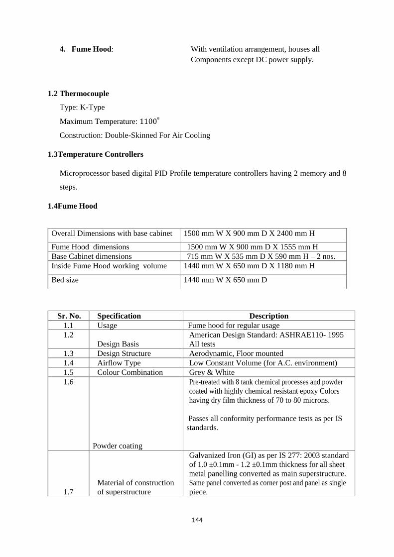
144
4. Fume Hood: With ventilation arrangement, houses all
Components except DC power supply.
1.2 Thermocouple
Type: K-Type
Maximum Temperature: 1100º
Construction: Double-Skinned For Air Cooling
1.3Temperature Controllers
Microprocessor based digital PID Profile temperature controllers having 2 memory and 8
steps.
1.4Fume Hood
Overall Dimensions with base cabinet 1500 mm W X 900 mm D X 2400 mm H
Fume Hood dimensions 1500 mm W X 900 mm D X 1555 mm H
Base Cabinet dimensions 715 mm W X 535 mm D X 590 mm H – 2 nos.
Inside Fume Hood working volume 1440 mm W X 650 mm D X 1180 mm H
Bed size 1440 mm W X 650 mm D
Sr. No. Specification Description
1.1 Usage Fume hood for regular usage
1.2
Design Basis
American Design Standard: ASHRAE110- 1995
All tests
1.3 Design Structure Aerodynamic, Floor mounted
1.4 Airflow Type Low Constant Volume (for A.C. environment)
1.5 Colour Combination Grey & White
1.6
Powder coating
Pre-treated with 8 tank chemical processes and powder
coated with highly chemical resistant epoxy Colors
having dry film thickness of 70 to 80 microns.
Passes all conformity performance tests as per IS
standards.
1.7
Material of construction
of superstructure
Galvanized Iron (GI) as per IS 277: 2003 standard
of 1.0 ±0.1mm - 1.2 ±0.1mm thickness for all sheet
metal panelling converted as main superstructure.
Same panel converted as corner post and panel as single
piece.

145
1.8 Front Top Panel
Easily openable hinged Top Panel for easy access to
Flow Control Valve and Electrical Lighting
fixtures for maintenance
1.9 Corner Post Panel profiled Corner Post is placed on Left and Right-Hand Side of the Fume hood
1.10 Construction (Interior)
Chemical & Heat Resistant, Fire Retardant, Smooth Finish, Easily Cleanable Panels made of durable PRL integral work
1.11
Active Kinetics exhaust
system
Interstitial 7-point active kinetics exhaust system (for
light, normal & heavy fumes) with baffle to ensure
rapid exhaust of fumes.
1.12 Airfoil
Aerodynamic Design, Horizontal fixed airfoil mounted
on the
1.13 Worktop
worktop made of SS 304 (1.2 ±0.1mm
thick).Chemical resistant splash & spillage proof
dished ‘Jet Black Granite’ worktop (18 +1 mm thick).
Skirting of 15 mm from all
1.14
Sink, Water tap with
drain arrangement
Worktop shall have a sink sealed with silicon sealant for drainage with a water tap on left on the back side of the worktop. Sink shall have a watertrap for waste collection
1.15
Sash (Shutter)
Vertical rising sash counter-balance with pulley and
counter-weight system. Toughened Float Glass sash
(5 mm thick). Smooth and light sash operation. Clear
openable height = 750 mm. Breaking Stress value for
fully toughened glass (Tempered Glass) = 24,000 psi.
1.16
Wet & Dry Service valves
Remotely operated Colour Coded Brass Needle Valves
for fine control over utilities (as per DIN 12920
norms) total 4 nos. service valves with PU
plumbing with 6 mm internal
diameterwithstandsupto 5kgf pressure
1 for Raw water (PU)
1 for Nitrogen (PU)
1 for Vacuum (Teflon)
1 for Compressed Air (PU)
1.17
Internal nozzles
Brass powder coated fittings staggered in the fume hood
on the back wall to avoid the intermingling of the
flexible hoses. Also, the taps shall be tapered in shape to
use with flexible tubing of sizes from ¼” to ½” in
dia to provide greater flexibility
1.18 Lighting
Fluorescent light (40 watt, 2 Nos.) with vapour-proof
fitting for proper illumination. Intensity approx. 400
lux at worktop level.
1.19 Electrical Utilities
3 nos. electrical sockets (230 V, 6/16 A, 50 Hz),
3 nos. MCBs with blower NO/NC switch with built –
in starter & light switch on front fascia. Cables &
wires shall be ‘Fire Retardant’ grade. (All on
RHS)

146
1.5 Thermal Characterization
1.20 Built-in Starter
The electrical wiring shall have built-in starter
suitable to blower motor capacity
1.21 Cable entering port
For easy access of cables from fume hood to electrical
sockets
1.22
Chemical Storage Base
Cabinet (Ventilated &on
castors)
It will have following features:
1) Completely made from 1mm thick GI sheet
with highly corrosion resistant epoxy powder
coating 60-80 microns thickness
2) Cabinet integral work walls shall be special
chemical &heat resistant, smooth finish, easily
cleanable panels made of durable PRL sheets
3) Two exhaust ports connected to the fume hood
exhaust system internally
4) One removable horizontal partition to store
chemicals
5) PP Trays for chemical storage
6) Cabinets on castors
1.23 Air Flow Monitor
To indicate the approximate face velocity of
airflow with primary purpose of warning when a low
flow condition occurs. Red & green LEDs
correspond to low & normal flow rates. When flow
decreases from Normal to Low, an audible alarm
shall also actuate requiring manual acknowledgement
for silence.
Digital display of face velocity in m/sec or fpm
On screen display for Safe and Alarm conditions
with Audible alarm and LED indication
Push button calibration and configuration
5. programmable output relays
3 configurable inputs
Com port for local or PC network connection
1.24 Level adjusting screws
Made of SS Bolts to adjust the fume hood level by +
10 mm.
1.25 Exhaust Port
Fumes shall be exhausted smoothly without any
turbulence at the exhaust port.
1.26 Flow control valve To regulate airflow
1.27 Noise Level < 70db at 1 meter from fume hood.

147
(a) Thermo Gravimetry (TG): Thermo gravimetric technique was used to understand
temperature based changes in the structure of swelling clay. This technique was also utilized
for long term performance assessment of swelling clays, to examine time-temperature
dependent mineralogical transformations, thermal stability of clay and effect of ground water
chemistry on desirable geotechnical properties. The thermo gravimetric (TG) analysis is based
on the principle of monitoring the known weight of a material or a mixture as a function of
temperature, using a thermo-balance of high sensitivity, during a predetermined heating or
cooling cycle. The weight changes can be monitored during heating as well as cooling or as a
function of time (isothermal) in a specified atmosphere. The schematic diagram of a thermo-
balance is shown in Figure 1.
Figure 1 Schematic diagram of a thermo-balance
The resulting thermo-gravimetric curve (change in weight versus temperature) provides
information concerning the thermal stability and composition of initial sample, thermal
stability & composition of any intermediate compounds that may be formed and the
composition of the residue, if any. This technique was very useful to estimate the moisture
content and bound / structured water in swelling clay.
(b) Differential Thermal Analysis (DTA): DTA technique was used to understand the process
of elimination of free and structural water molecules from the swelling clay particles to
ascertain thermal stability under repository conditions. In this technique, the differential
temperature (ΔT) of sample, with respect to the temperature of a thermally inert material,
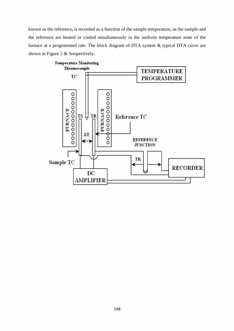
148
known as the reference, is recorded as a function of the sample temperature, as the sample and
the reference are heated or cooled simultaneously in the uniform temperature zone of the
furnace at a programmed rate. The block diagram of DTA system & typical DTA curve are
shown in Figure 2 & 3respectively.

149
Figure 2 Block diagram of DTA system
Figure 3 A typical DTA curve
The curve is described by the characteristic temperatures. The initiation temperature (Ti), the
peak temperature (Tp) and the termination temperature (Tf) are the three temperatures used to
characterize the main features of the DTA curve. The initiation temperature represents the
temperature where the DTA signal begins to deviate from a steady baseline. The extrapolated
onset temperature (Te) corresponding to the point of intersection of the baseline with the
tangent drawn to the rising part of the DTA curve at the point of maximum slope is often
preferred to the initiation temperature. The peak temperature indicates either the end of the
reaction of transformation or the temperature at which the rate of transformation is maximum
and finally Tf denotes the temperature at which the signal returns to the baseline. The
temperature changes in the sample can be due to enthalpy changes caused by phase transitions,
mineralogical transformation, fusion, decomposition reactions, oxidation or reduction
reactions, etc. The instrumental factors that influence the DTA signal are the geometry and
material of the sample holder, nature of the thermocouple and its location, the heating rate and
the atmosphere around the sample. The sample characteristics like the particle size, amount of
sample used, its heat capacity and thermal conductivity and packing density also play an
important role in affecting the DTA curve. The DTA instrument requires calibration for

150
temperature. Several standard materials like pure metals and well characterized compounds
have been recommended for this purpose. The melting points of metals like In, Zn, Sn, Sb, Al,
Ag and Au and phase transitions in Li2SO4, K2CrO4, BaCO3etc can be used for temperature
calibration. In the present work, thermal characterization was carried out using a commercial
TG-DTA unit in static air at a heating rate of 10 K min−1 against alumina as standard.
1.6 RAMAN SPECTROMETER
Sr No. Description Technical Specifications
1 Make JobinYvon Horiba HR-800 Evolution
2 Laser 532nm Diode Pumped Solid State Laser and 633nm He-
Ne Laser.
3 Monochromator 800 mm focal length achromatic
flat field monochromator. Two
gratings, 1800 l/mm and 600
l/mm –fully automated
4 Resolution 0.35 cm
-1
/pixel with 1800 l/mm
grating and 633 nm laser
5 Detector Peltier cooled Synapse
Figure 4 RAMAN SPECTROMETER

151
1.7 Glass Resistivity Measurement Technique
The electrical resistivity of molten glass decreases as its temperature increases. The conduction
in molten glass is mainly due to electrolytic conduction by different ionic species. Hence
resistivity of the molten glass can be easily controlled by alkali cations like Na, K, Li which
act as glass modifiers. However higher alkali content reduces the chemical durability of the
final waste product. In view of this, a balance between concentration of glass modifier, network
formers and glass intermediate is very important while formulating the glass composition.
1 molar KCl solution was prepared for finding electrode constant. The LCR meter was set with
100 kHz. Electrode setup was inserted in the KCl solution such that the two electrodes dipped
in to 50% of total solution height and the resistance was measured through LCR meter. The
conductivity of 1 molar KCl solutions is 0.111303𝑚−1𝑚ℎ𝑜. So dividing the resistivity by
measured impedance, gives electrode constant (L/A).
Figure 5 Experiment setup for glass resistivity measurement

152
1.7.1 Measurement Procedure:
The molten glass in the ceramic crucible was positioned properly in the furnace. The glass was
melted initially and then the electrode setup was introduced. The electrodes were immersed in
the molten glass at least 2.0 cm below the surface; this was done to ensure that the top and
bottom fringe fields were not disturbed with the wall. Then glass temperature was increased up
to 1100˚C, after that the power supply to the furnace was switched off for measuring the
impedance. While measuring, the power supply was switched off for protection to the LCR
meter due to differential voltage induced in the electrodes. The temperature of the molten glass
was decreased due to cooling and the reading of the meter gives different impedance value with
respect to decreased temperature. There is two temperature reading, one is furnace temperature
and other is inside crucible glass temperature. After switch off the furnace power supply, the
furnace temperature decreases firstly compare to crucible glass temperature.
1.8 Results for prototype cavity
1.8.1 Microwave heating of e waste experimental results:
For this thesis, experiments were done for e-waste pyrolysis using already available applicators
namely induction heating, resistive heating and microwave heating. Feasibility of microwave
heating for e waste was established through these experiments. Along with these experiments,
modeling and simulation work was carried out using CST Microwave studio. Optimized cavity
after this analysis was fabricated and prototype microwave applicator system was setup as per
block diagram 3.1. Using this cavity heating time for e waste has been reduced from 5-6
minutes to 3-4 minutes. Brief summary of these comparative results is given in table below.

153
1.8.1.1 Comparative results for different type of heating methods
Technique
Parameters
Value
Resistance Induction Microwave
(Commercial)
Microwave
(Prototype)
Scale 5 g 5 g 5 g 5 g
Temperature, º
C
415 415 350 410
Weight loss, % 19.45 22.93 25.1 34
Time, Minutes 25-35 min 25-35 min 5-6 min 3-4 min
1.8.1.2 Temperature profile for FR-4 dielectric in different cavities:
Cavity 3 was optimized for FR-4 dielectric as this dielectric forms the base for most of the
electronic waste in general. Temperature profile of FR-4 in different cavities is shown in figure
6 (a), (b), (c). These results have been obtained using CST Microwave Studio, Multiphysics
Studio. As it is clear temperature profile is more uniform in case of cavity 3.
Profile of Goethite Inside Cavity 3
Figure 6 (a) Temperature profile in cavity 3 for FR-4 dielectric

154
Figure 6 (b) Temperature profile in cavity 2 for FR-4 dielectric
Figure 6 (c) Temperature profile in cavity 1 for FR-4 dielectric
1.8.2 Comparison of different Cavities for Nuclear Waste:
In case of nuclear waste, cavity 3 was optimized for the surrogate material i.e. Goethite and
for Lithium borosilicate glass, identified for encapsulation of Technetium (99Tc) by
establishing its suitability for heating through simulations. Temperature variation of goethite
block with time is shown in figure 7(a), (b), (c). These results are obtained through coupled
simulations done in CST Microwave Studio, Multi physics Studio. As it is clear from figures
in case of cavity 2, temperature of Goethite is very high, which exceeds the melting temperature
for Goethite. Due to this reason cavity 2 becomes unusable for Nuclear Waste management.
While cavity 1 and cavity 3 both are suitable for Nuclear Waste management. Feasibility of
cavity 3 usage for nuclear waste management is established through modeling and simulations.

155
Figure 7 (a) Temperature vs Time for Goethite in cavity 3
Figure 7 (b) Temperature vs Time for Goethite in cavity 2
figure 7 (c) Temperature vs Time for Goethite in cavity 1

156
Temperature variation of lithium borosilicate with time is shown in figure 8 (a), (b), (c).
These results are obtained through coupled simulations done in CST Microwave Studio,
Multi physics Studio. As it is clear from figures in case of cavity 1, temperature of lithium
borosilicate does not rise high enough up to the melting temperature of glass, rendering
the cavity 1 unusable for Nuclear Waste management(99Tc). Thus, it is found that cavity 3 is
only suitable for the Nuclear Waste management (99Tc). Feasibility of cavity 3 usage for
nuclear waste management (99Tc) is established through modeling and simulations.
Figure 8 (a) Temperature vs Time for Lithium borosilicate in cavity 1
Figure 8 (b) Temperature vs Time for Lithium borosilicate in cavity 2

157
Figure 8 (c) Temperature vs Time for Lithium borosilicate in cavity 3
Optimization of new cavity for nuclear waste was limited on the ground of permissions and
sanctions required for handling nuclear material. Optimization of microwave cavity for nuclear
waste though experiments was restricted to the facilities readily available in the plant
laboratories due to regulatory limitations. Experimental analysis for the prototype system
developed, requires prior safety clearances and BSC authorization for installation and trial runs
in active laboratories. Prototype system developed has been tested for surrogate materials as
per practical feasibility of doing experimental analysis in the inactive lab facility available for
the cavity. Simulations done in cavity 1,2,3 show that cavity 1 & 3 are suitable for goethite
heating, as cavity 2 gets temperature in excess of melting temperature of goethite. While cavity
1 is not suitable for heating Lithium Borosilicate glass up to the melting point. So cavity 3
alone is suitable for N waste treatment (99Tc ).

158
Appendix 2- Microwave Heating Basics
Microwave Heating in Dielectric Material:
Dielectrics (insulators) materials have positive and negative charges which are bound by
atomic and molecular forces, thus ideally a dielectric should not contain any free charges.
When a dielectric is subjected to electric field, dipoles formed within dielectric material interact
with this electric field. The behavior of these dipoles and bound charges under applied electric
field is accounted for in a qualitative way by introducing an electric polarization vector P.
𝐷 = 휀0𝐸 + 𝑃 ------------ (1)
Where D is electric flux density, E is applied electric field and P is electric polarization vector.
𝐷 = 휀0𝐸 + 휀0𝜒𝑒𝐸 = 휀0(1 + 𝜒𝑒)𝐸 = 휀0휀𝑟𝐸 ---------- (2)
Where 𝜒𝑒 is electric susceptibility, 휀0 is electric permittivity of free space and 휀𝑟 is relative
permittivity of dielectric. When the applied electric field is alternating in nature, polarization vector P and permittivity
in turn get affected and they are functions of frequency of alternating electric field. In this case
electric flux density can be represented as following.
𝐷 = 휀0휀𝑟∗𝐸 = 휀0(휀𝑟
′ − 𝑗휀𝑟′′)𝐸 ----------- (3)
Where 휀𝑟∗ is complex permittivity, which constitutes of real and imaginary part. Imaginary part
of permittivity is responsible for dielectric heating.
Now the Maxwell ampere equation for above case can be written as:
∇ × 𝐻 = 𝐽𝑖 + 𝐽𝑐 + 𝐽𝑑 = 𝐽𝑖 + 𝜎𝑠𝐸 + 𝑗𝜔(휀′ − 𝑗휀′′)𝐸 ----------- (4)
Where 𝐽𝑖 is impressed current density, 𝐽𝑐 is conduction current density and 𝐽𝑑 is displacement
current density. H magnetic field intensity, E is electric field, 𝜎𝑠 is static field conductivity, 휀′
is real part of dielectric constant and 휀 ′′ is imaginary part of dielectric constant.
∇ × 𝐻 = 𝐽𝑖 + (𝜎𝑠 + 𝜔휀′′)𝐸 + 𝑗𝜔휀′𝐸 = 𝐽𝑖 + 𝜎𝑒𝐸 + 𝑗𝜔휀′𝐸 ----------- (5)
Where 𝜎𝑒is equivalent conductivity. Now total current density Jt is can be written as
∇ × 𝐻 = 𝐽𝑡 = 𝐽𝑖 + 𝑗𝜔휀′ (1 − 𝑗𝜎𝑒
𝜔𝜀′) 𝐸 = 𝐽𝑖 + 𝑗𝜔휀′(1 − 𝑗. 𝑡𝑎𝑛𝛿𝑒)𝐸 ----------- (6)
Where 𝑡𝑎𝑛𝛿𝑒 is effective electric loss tangent which is defined by following equation:
𝑡𝑎𝑛𝛿𝑒 =𝜎𝑠+𝜔𝜀′′
𝜔𝜀′=
𝜎𝑠
𝜔𝜀′+
𝜀′′
𝜀′= 𝑡𝑎𝑛𝛿𝑠 + 𝑡𝑎𝑛𝛿𝑎 --------------- (7)
Where 𝑡𝑎𝑛𝛿𝑠 is static electric loss tangent and 𝑡𝑎𝑛𝛿𝑎 is alternating electric loss tangent.

159
1. Theorem for dielectric heating:
Microwave heating of dielectric materials as explained above is caused due to imaginary part
of dielectric constant, which is due to dipole rotation in alternating electric field. But
microwave heating phenomena can be explained on the basis of work energy theorem or
“Poynting’s Theorem”.
“Poynting’s Theorem” states, “The work done on charges by electromagnetic force is equal to
the decrease in energy stored in field, less the energy that flowed out through the surface.”
𝑑𝑊
𝑑𝑡= −
𝑑
𝑑𝑡∫
1
2
𝑞
𝑉(휀0𝐸2 +
1
𝜇0𝐵2) 𝑑𝑣 −
1
𝜇0∮ (𝐸 × 𝐵). 𝑑𝑎
𝑎
𝑺 ---------------- (8)
Above equation can also be written in more compact manner as
𝑑𝑊
𝑑𝑡= −
𝑑
𝑑𝑡𝑈𝑒𝑚 −
1
𝜇0∮ 𝑆. 𝑑𝑎
𝑎
𝑺 ---------------- (9)
Where dW/dt is rate of work done, E & B are electric field intensity and magnetic flux density,
V is the total volume and dv is infinitesimal volume. da is infinitesimal area and ∮ 𝑎𝑎
𝑺represents
integral over a closed surface. 𝑈𝑒𝑚 is total electromagnetic energy.
From equation (8) and equation (5), the component of current which is responsible for dielectric
heating is given by 𝜎𝑒𝐸. Accordingly, heat dissipated in dielectric per unit volume Pv is given
by:
𝑃𝑣 =1
2𝑅𝑒(𝐸. 𝐽∗) =
1
2𝜎𝑒|𝐸|2 =
1
2𝜔휀′𝑡𝑎𝑛𝛿𝑒|𝐸|2 = 2𝜋𝑓휀′𝑡𝑎𝑛𝛿𝑒𝐸𝑟𝑚𝑠
2 -------- (10)
Erms is time averaged value of electric field. Now above equation is used as a source term in
multi physics solver while solving for rise in temperature as shown in equation 4.6.
2. Dielectric Heating of Borosilicate Glass:
Now as defined earlier properties of borosilicate glass used in experiments and modeling are
following:
6. Density = 2.66 g/cc
7. ε' @ 20oC = 8.01
8. tan δ = 5 ×10⁻³
9. Thermal conductivity = 0.45 W.m-1.K-1
Heat capacity of Lithium Borosilicate is a temperature dependent material property which
varies over temperature range and was suitably modeled in computer model.
Dielectric heating of borosilicate glass depends on dielectric loss tangent, and dependent on
absorption of microwaves in borosilicate glass.
As discussed earlier 𝑡𝑎𝑛𝛿𝑒 is responsible for heating of dielectric, in case of air loss tangent is
zero, dielectric constant is 1. Distill water is having equivalent loss tangent of 0.16 at 3 GHz,
dielectric constant is 77. BSBZ (Borosilicate Bismuth Zinc) glass has a loss tangent of 0.01,
and dielectric constant is 21.

160
3. Electromagnetic wave propagation in microwave heating:
Rectangular multimode/ single mode microwave cavity are actually multimode/ single mode
waveguide with closed ends, with an open port for waveguide. Solution of wave equations in
cavity is derived similar to wave equation solutions in waveguide.
The electric and magnetic wave equations in frequency domain are given by following
equations:
∇2𝐸 = 𝛾2𝐸
∇2𝐻 = 𝛾2𝐻} --------- (11)
Where E is electric field intensity and H is magnetic field intensity, intrinsic propagation
constant of medium is given by 𝛾 = √𝑗𝜔𝜇(𝜎 + 𝑗𝜔휀) . These two equations collectively are
known as vector wave equations. Here it is to be noted that ∇2is a scalar operator defined as
∇. ∇ . The rectangular components of E and H satisfy complex scalar wave equation which is known
as Helmholtz equation.
∇2𝜓 = 𝛾2𝜓 ------------ (12)
Helmholtz equation in rectangular coordinates can be represented by following equation.
𝜕2𝜓
𝜕𝑥2+
𝜕2𝜓
𝜕𝑦2+
𝜕2𝜓
𝜕𝑧2= 𝛾2𝜓 ---------- (13)
This is a linear inhomogeneous, partial differential equation which is solved using variable
separable method.
Total solution of Helmholtz equation in rectangular coordinates is given by following equation
𝜓 = [𝐴 𝑆𝑖𝑛(𝑘𝑥𝑥) + 𝐵 𝐶𝑜𝑠(𝑘𝑥𝑥)][𝐶 𝑆𝑖𝑛(𝑘𝑦𝑦) + 𝐷 𝐶𝑜𝑠(𝑘𝑦𝑦)][𝐸 𝑆𝑖𝑛(𝑘𝑧𝑧) +
𝐹 𝐶𝑜𝑠(𝑘𝑧𝑧)] -------------- (14)
Where 𝛾 is related to 𝑘𝑥, 𝑘𝑦, 𝑘𝑧 by following equation:
𝛾2 = −𝑘𝑥2−𝑘𝑦
2−𝑘𝑧
2 -------- (15)
Now solutions of this equation for particular case of multimode rectangular cavity are
explained in section 3.2.1 of thesis. Which are given by following equations:
𝐻𝑧 = 𝐻0𝑧𝑐𝑜𝑠 (𝑙𝜋𝑥
𝑎) 𝑐𝑜𝑠 (
𝑚𝜋𝑦
𝑏) 𝑠𝑖𝑛 (
𝑛𝜋𝑧
𝑑) TElmn mode -------- (16)
𝐸𝑧 = 𝐸0𝑧𝑠𝑖𝑛 (𝑙𝜋𝑥
𝑎) 𝑠𝑖𝑛 (
𝑚𝜋𝑦
𝑏) 𝑐𝑜𝑠 (
𝑛𝜋𝑧
𝑑) TMlmn mode --------- (17)
Where l = 0, 1, 2, 3… represents the number of half wave cycles in x direction, m = 0, 1, 2, 3…
represents the number of half wave cycles in y direction, and n = 0, 1, 2, 3… represents the

161
number of half wave cycles in z direction. a, b are dimensions in X, Y direction and d is depth
of cavity in Z direction.
The idealized cavity for which the above solutions are strictly valid is closed on all sides and
is known as a pillbox cavity. All practical cavities have one or two openings in the cavity walls
for waveguide feeds. Though the above given solutions become approximate for practical
cases, they serve as a good initial analytical solution for rectangular cavities.
Depending on load and position of feed port and input mode, different modes are excited in
cavity. These modes form standing wave patterns in cavity, in classical sense wave propagation
in cavity doesn’t take place, energy is lost in either waveguide walls or in dielectric load placed
inside the cavity.
4. Difference in single mode and multimode cavity:
Two types of microwave cavities are in general found in applicators namely single mode and
multimode cavities. In case of single mode cavities, applicator is designed to operate in a single
resonant mode. In this type of cavities, dimensions of cavity are determined in such a way that
in loaded condition resonant frequency of cavity coincides with source frequency. These
cavities are in general highly resonant, load specific and characterized by high quality factor.
As only one mode is excited and present inside the cavity, solutions for this cavity can be
determined analytically. These cavities are designed in such a way that higher order modes
occur at frequencies considerably greater than that of operating frequency. For example in a
cylindrical cavity designed for TM010 mode operation, TM020 mode should occur at much
higher frequency than the resonant frequency. This helps in keeping the resonant modes well
separated unless the cavity is very heavily loaded. The mode pattern for this cavity will not
change significantly due to change of frequency. However, field magnitude can significantly
alter in this case.
A multimode cavity, generally rectangular in shape is a metallic enclosure which can support
large number of resonant modes. A single or double waveguide feeds are provided to couple
the cavity with microwave source. Multimode cavities are capable of accepting different type
of loads with different geometries and material properties. Multimode cavities typically have
lower quality factors in comparison to single mode cavities. Due to their flexibility multimode
cavities are used in wide range of applications including domestic microwave ovens.
Multimode cavity derives its name from its ability to support large number of resonant modes
near to operating frequency, which combine to give some better degree of uniformity. The
heating of dielectrics inside multimode system is difficult to analyze, however qualitatively
solutions have been possible analytically. For exact solutions computer aided design tools are
required for full wave solutions in this type of cavities.
5. Processes During off gas analysis:
The products formed suggest that "On heating the waste/e-waste, it
degrades involving complex physico-chemical processes of sublimation, oxidation
and thermal dissociation leading to formation of various gaseous products
(such as carbon dioxide, acetylene), volatile organic compounds (for example,
acetone, oxetane etc.) and solid matter".
References:
1.C. A. Balanis, “Advanced Engineering Electromagnetics,” 2nd edition, John Wiley and Sons,
2012.

162
2.David. J. Griffiths, “Introduction to Electrodynamics,” 3rd edition, Prentice Hall Inc., 1999.
3.Samuel Y. Liao, “Microwave Devices and Circuits,” 3rd edition, Prentice Hall, New Jersey,
2003.
4.http://literature.cdn.keysight.com/litweb/pdf/genesys200801/elements/substrate_tables.

Thesis Highlight
Name of the Student: Hrishikesh Mishra Name of CI/OCC: BARC Mumbai Enrolment No: ENGG01201718002 Thesis Title: Design and Optimization of Microwave System for Energy Efficient Remediation of Nuclear and E-Waste Discipline: Engineering Sciences Sub-Area of Discipline: Electrical Engineering Date of viva voce: 10/06/2021 Thesis explores viability of microwave assisted processing of e-waste and nuclear waste management for challenging long lived radio nuclides i.e. Technetium (99Tc). The thesis work addresses computer aided design, simulation and optimisation of a microwave heating system for heterogeneous waste streams, including extensive comparative studies with conventional heating techniques for performance evaluation. The research work covers detailed case studies on experimentation of nuclear waste & e-waste with comparative analysis for microwave & conventional heating system. The study finds that microwave assisted e-waste processing is much more rapid, safe and superior, compared to the resistive & inductive heating in terms of process variables, mass &
volume reduction, time consumed, evolved gaseous discharges, residues and overall system efficiency. Thermo-Gravimetry (TG) and differential thermal analysis (DTA) were performed for determining change in mass and heat loss for electronic waste. The study also concludes that problem of long lived radio-nuclide (99Tc) can be satisfactorily addressed with encapsulation & consolidation of 99Tc bearing Fe-corrosion products (i.e. Goethite) in suitable glass matrices through microwave heating. Process flow for nuclear waste remediation is shown in figure 1. Comparative results for the research study on e waste are highlighted in table 1 given below.
Figure 1: Process flow showing reductive mineralization of Tc in Fe corrosion product followed by encapsulation of the Tc bearing corrosion product in glass.
Table 1: Comparative results for different heating methods Figure 2:Microwave heating set-up within a fume hood Photograph of a prototype microwave system developed based on the results of this thesis is shown in figure 2.
key words : nu waste, e waste, microwave system, Technetium(99Tc) , goethite, TG/DTA , remediation, simulation