Embed Size (px)
Citation preview
Design and Optimization of an Electric Car Chassisand Body using Structural Analysis and CFDMohammed Aiyan ( [email protected] )
BMSIT: BMS Institute of Technology https://orcid.org/0000-0003-3587-7315Sumanth Sagar
BMS Institute of TechnologySanjay Raghav S
BMS Institute of Technology https://orcid.org/0000-0002-5853-9506
Research Article
Keywords: Electric Car, Finite Element Analysis, Computational Fluid Dynamics, Composite Materials
Posted Date: June 1st, 2021
DOI: https://doi.org/10.21203/rs.3.rs-575396/v1
License: This work is licensed under a Creative Commons Attribution 4.0 International License. Read Full License
Title: “Design and Optimization of an Electric Car Chassis and Body
using Structural Analysis and CFD”
Authors:
Mohammad Aiyan
BMS Institute of Technology & Mgmt., Mechanical Engineering, Bangalore, India
ORCID: 0000-0003-3587-7315
S Sumanth Sagar
BMS Institute of Technology & Mgmt., Mechanical Engineering, Bangalore, India
ORCID: 0000-0001-7967-7548
Sanjay Raghav S (Corresponding Author)
BMS Institute of Technology & Mgmt., Mechanical Engineering, Bangalore, India
Email: [email protected]
ORCID: 0000-0002-5853-9506
DECLARATION
Funding (Non-Applicable)
Conflicts of Interest/Competing Interest - On behalf of all authors, the corresponding author states that there
is no conflict of interest.
Availability of Data and Material (Applicable)
Code Availability (Non-Applicable)
Ethics Approval (Non-Applicable)
Consent to Participate (Applicable)
Consent for Publication (Applicable)
Design and Optimization of an Electric Car Chassis
and Body using Structural Analysis and CFD Mohammad Aiyan, S Sumanth Sagar, Sanjay Raghav S (Corresponding Author)
Abstract - The transition from traditional gasoline-powered
automobiles to electric vehicles (EVs) has taken time, two major
challenges of engine- powered vehicles are greenhouse gas
emissions and fuel economy. Electric cars require less
maintenance. A lot of money can be saved while also helping the
environment. In today's world, working with lightweight
materials have emerged as a key area for improvement in the
automotive industry. The most efficient method for increasing
power output is to reduce the weight of vehicle components.
Composite materials have benefited greatly from research and
development because they are stronger, more recyclable, and
easier to integrate into vehicles. The primary goal of this
research is to design the body and chassis frame of a two-seater
electric car. A CFD analysis was performed to determine the
drag coefficient of the body along with structural analysis to
obtain the frontal impact and torsional rigidity of the chassis to
develop an effective electric car design. The design was carried
out with the help of CATIA V5 software, while the analysis was
performed using ANSYS 19.2. A comparative analysis of the
chassis was undertaken by incorporating three different
materials namely, traditional steel i.e., Stainless Steel 304L,
Aluminium Alloy 7075-T6, T300 Carbon Fibre composite. The
energy efficiency of the car for the three materials are also
computed.
Keywords- Electric Car, Finite Element Analysis, Computational
Fluid Dynamics, Composite Materials
1. INTRODUCTION
One of the main contributors to the greenhouse effect is the
burning of fossil fuels for transportation and heating. The
transport sector is currently the main consumer of fossil fuels.
Hence, car manufacturers are starting to implement a more
sustainable approach when developing vehicles with the
focus on electric vehicles. Electric cars are emerging as a
promising solution for the near future. Being battery
powered, these vehicles do not perform as well as the
conventional automobiles, and hence they need to be
optimized effectively on all other fronts to derive maximum
performance from electric power. The two most effective
approaches to do this would be to improve the vehicle's
aerodynamics and make it as light as feasible. At highway
speeds, an electric vehicle's air resistance can reach up to 48%
of its total driving resistance. (Tamer Nabil*, 2020)
Aerodynamic design of cars is crucial as it directly affects the
fuel economy and stability in motion. A virtual wind tunnel
can be developed with the help of CFD analysis in order to
obtain the drag force on the vehicle body. A streamlined car
has less drag, whereas a boxy vehicle, such as a bus, has a
high aerodynamic drag; thus, the goal of this research is to
develop a practically streamlined body to maximise the
performance of the electric car.
The second aspect of this project is to design a
chassis for the electric car. In general, achieving lightweight
and rigid automobile structures plays a critical role in
maximising electric car efficiency. Without a doubt, the
chassis is one of the most crucial components of the
construction. As a result, it must be constructed in such a way
that it reduces weight while improving total vehicle
performance. In order to meet the strength, low
manufacturing cost, and aesthetic standards of common
lightweight urban cars, space frame structures are frequently
used (R.K. Kawade, 2017). A space frame chassis was chosen
for the study as it is rigid, lightweight, cost effective and
simple to manufacture. On the other hand, chassis stiffness
requirements make any weight reduction difficult and costly.
For the development of both high-performance and cost-
effective road vehicles, the problem of finding the best
compromise between chassis stiffness, weight, and cost is
critical. (Luiz CarlosGertz, 2015) The structural components
of the chassis frame, such as cross members, must be
strategically located to reduce frame twist and minimise local
deflections of suspension mounting brackets. Chassis
stiffness is a direct factor of torsional rigidity. Increasing the
torsional rigidity of a vehicle improves ride comfort quality
by allowing the suspension to work more efficiently.
The torsional rigidity of a vehicle’s chassis can be
defined as "how much a frame will flex as it is loaded when
one front wheel is up and one front wheel is down while the
rear of the car is held level" in simple terms. Having a good
torsional rigidity results in good handling. The task of
designing a chassis is to improve the torsional stiffness
without compromising the its weight. One way of doing this
is to incorporate lightweight materials into the chassis. The
rising popularity of composite materials such as Fibre
Reinforced Plastics (FRPs) and Metal Matrix Composites
(MMCs) has made it possible for these materials to find
applications in the automotive industry. Carbon fibres are an
excellent choice of material when it comes to chassis building
due to their high strength, lightweight, thermal resistance and
flexibility. (H Ahmad, 2020) In this study, a comparison is
made between carbon fibre chassis, the traditionally used
stainless steel and newly introduced aluminium alloy.
2. MODELLING
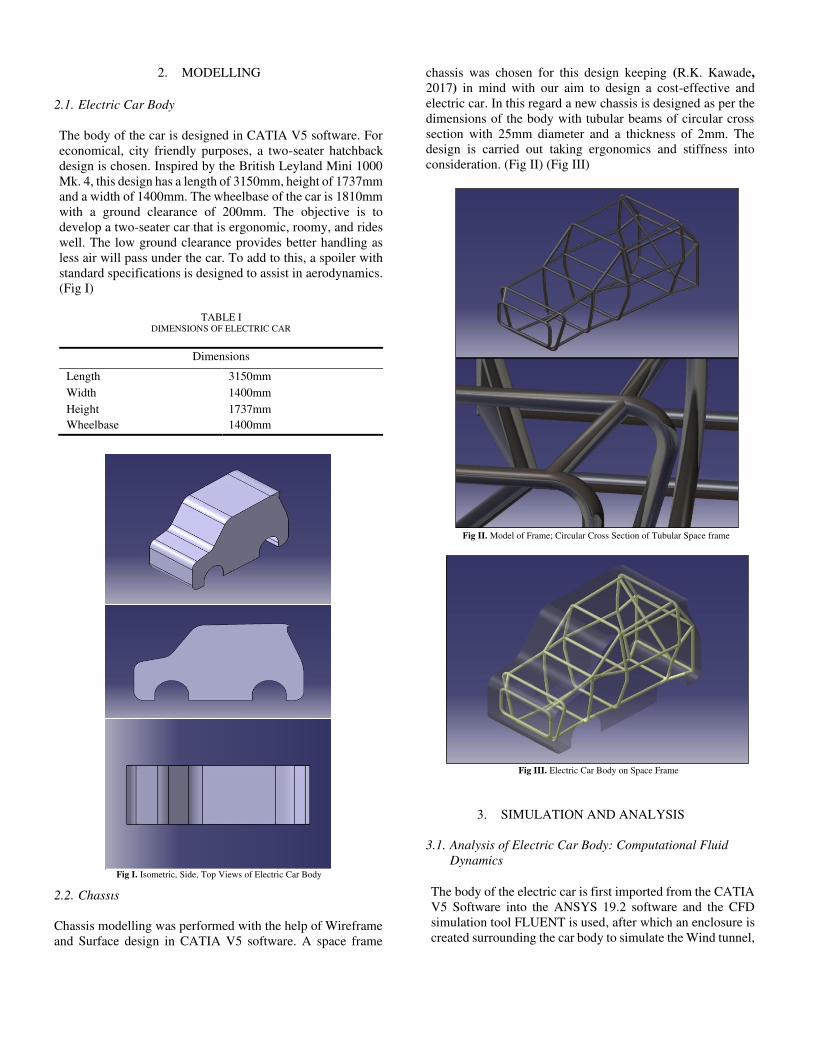
2.1. Electric Car Body
The body of the car is designed in CATIA V5 software. For
economical, city friendly purposes, a two-seater hatchback
design is chosen. Inspired by the British Leyland Mini 1000
Mk. 4, this design has a length of 3150mm, height of 1737mm
and a width of 1400mm. The wheelbase of the car is 1810mm
with a ground clearance of 200mm. The objective is to
develop a two-seater car that is ergonomic, roomy, and rides
well. The low ground clearance provides better handling as
less air will pass under the car. To add to this, a spoiler with
standard specifications is designed to assist in aerodynamics.
(Fig I)
TABLE I
DIMENSIONS OF ELECTRIC CAR
Dimensions
Length 3150mm
Width 1400mm
Height 1737mm
Wheelbase 1400mm
2.2. Chassis
Chassis modelling was performed with the help of Wireframe
and Surface design in CATIA V5 software. A space frame
chassis was chosen for this design keeping (R.K. Kawade,
2017) in mind with our aim to design a cost-effective and
electric car. In this regard a new chassis is designed as per the
dimensions of the body with tubular beams of circular cross
section with 25mm diameter and a thickness of 2mm. The
design is carried out taking ergonomics and stiffness into
consideration. (Fig II) (Fig III)
3. SIMULATION AND ANALYSIS
3.1. Analysis of Electric Car Body: Computational Fluid
Dynamics
The body of the electric car is first imported from the CATIA
V5 Software into the ANSYS 19.2 software and the CFD
simulation tool FLUENT is used, after which an enclosure is
created surrounding the car body to simulate the Wind tunnel,
Fig I. Isometric, Side, Top Views of Electric Car Body
Fig II. Model of Frame; Circular Cross Section of Tubular Space frame
Fig III. Electric Car Body on Space Frame
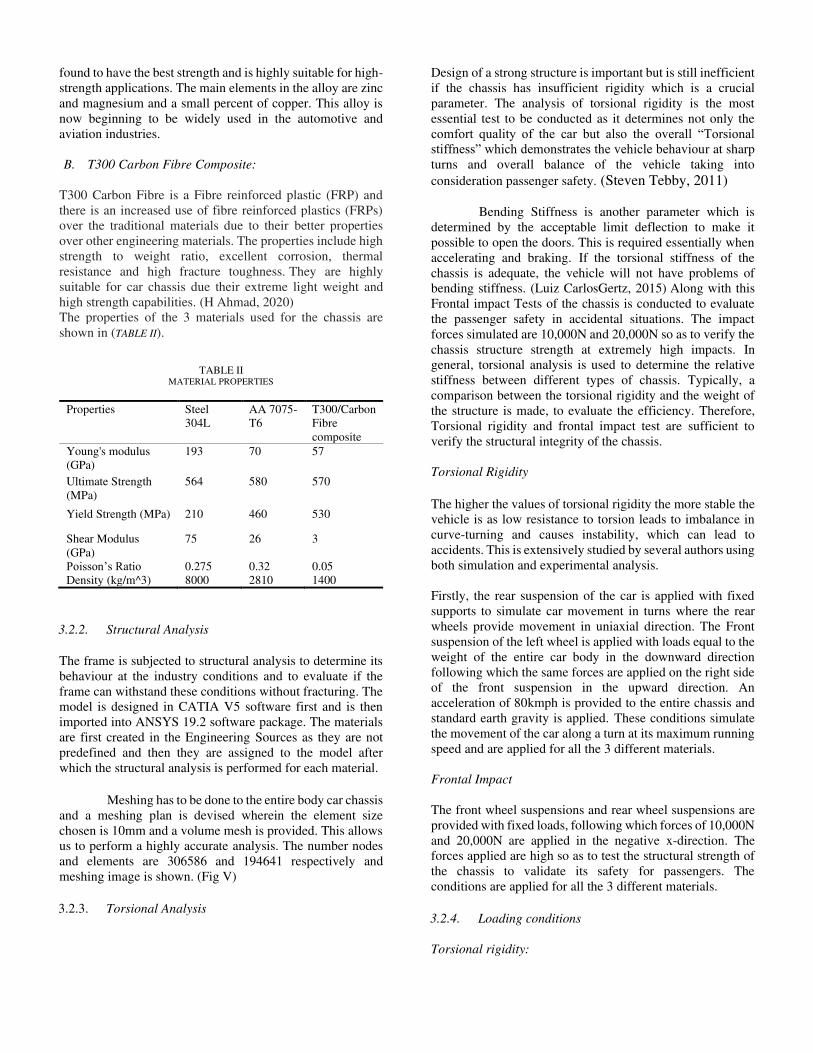
the dimensions are 12m,8m and 4.5m in the x, y and z
direction respectively. The inlet of the wind tunnel was
placed at half car-length in front of the car and the outlet was
2 times the car-length from behind the car to capture the flow
at the wake downstream of the car. (Louis Cattafesta, 2010)
Following this a volume mesh of 0.8m element size
and High smoothness is done with an incorporation of 10
layers of inflation. In aerodynamic simulations it is
recommended to refine the cells of the mesh in order to
determine any unsteady or turbulent fluid phenomena caused
by the separation of the boundary layer from the car body.
The number of nodes and elements being 82506 and 389924
respectively.
3.1.1. Boundary Conditions
The Boundary conditions are applied onto the meshing as
stated above. The wind tunnel-car body setup is then
specified to have a velocity inlet, a pressure outlet, the car
body and side-walls which are treated as non-Slip walls to
simulate the wind tunnel conditions. The analysis is carried
at three different inlet velocities of 40kmph, 60kmph and
80kmph and outlet pressure set at zero pascal for 200
iterations for the model so as to enable a thorough
comparative study of its performance at the real-world
conditions that the car body will be subjected to.
Turbulence Modelling: The Mach number is below 0.3
therefore the flow is incompressible and steady in nature. The
Reynolds Averaged Navier-Stokes RANS equations are
solved to simulate the incompressible turbulent flow and the
energy equation is not considered as there are no temperature
conditions. K-Epsilon (k-ε) realizable is taken as the turbulence model as it is ideal for external geometry with
flow separation. Pressure velocity coupling is used to
calculate the pressure field for which the COUPLE algorithm
is implemented.
The car body frame is subjected to 40kmph, 60kmph and
80kmph inlet velocity speeds so as to simulate the conditions
it will be subjected to while in Real-World use. To verify this
the Drag coefficient and Drag force values for the car were
calculated in the ANSYS FLUENT software. These
parameters help in determining if the car body can run at the
mentioned speeds without any disruptions. The values are
tabulated. (TABLE IV)
3.2. Analysis of Electric Car Chassis: Structural Analysis
3.2.1. Material Selection
The main parameters to be satisfied by the materials used for
the chassis of an electric car is that it should be lightweight
so as to reduce the load on the car battery, it should have a
high yield strength so as to be rigid, safe to be used for
passengers and it should be economical to manufacture. An
extensive study was carried out following which Aluminium
Alloy 7075-T6 and T300 which is a carbon fibre composite
are selected as the potential materials. Carbon fibre usually
combined with other materials to form a strong composite.
When impregnated with plastic resin such as epoxy and
baked, it forms carbon-fibre-reinforced polymer which has
high strength-to-weight ratio, and is extremely rigid. (H
Ahmad, 2020)
A comparative analysis of these materials is carried out
along with the traditionally used Steel 304L alloy. The
comparative analysis allows us to identify the most efficient
material for use. The mass of the chassis for each material
is listed below along with the percentage reduction in
weight. (
TABLE VI) The weight reduction in chassis plays an
important role as it affects the overall performance of the
vehicle.
A. Aluminium 7075-T651:
Aluminium 7075-T651 is a commonly used 7-series
Aluminium alloy. Among the other Aluminium alloys, it is
Fig IV. Meshing of Virtual Wind Tunnel
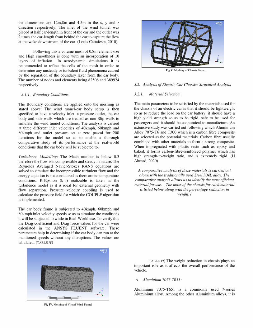
Fig V. Meshing of Chassis Frame
found to have the best strength and is highly suitable for high-
strength applications. The main elements in the alloy are zinc
and magnesium and a small percent of copper. This alloy is
now beginning to be widely used in the automotive and
aviation industries.
B. T300 Carbon Fibre Composite:
T300 Carbon Fibre is a Fibre reinforced plastic (FRP) and
there is an increased use of fibre reinforced plastics (FRPs)
over the traditional materials due to their better properties
over other engineering materials. The properties include high
strength to weight ratio, excellent corrosion, thermal
resistance and high fracture toughness. They are highly
suitable for car chassis due their extreme light weight and
high strength capabilities. (H Ahmad, 2020)
The properties of the 3 materials used for the chassis are
shown in (TABLE II).
TABLE II MATERIAL PROPERTIES
Properties Steel
304L
AA 7075-
T6
T300/Carbon
Fibre
composite
Young's modulus
(GPa)
193 70 57
Ultimate Strength
(MPa)
564 580 570
Yield Strength (MPa) 210 460 530
Shear Modulus
(GPa)
75 26 3
Poisson’s Ratio 0.275 0.32 0.05
Density (kg/m^3) 8000 2810 1400
3.2.2. Structural Analysis
The frame is subjected to structural analysis to determine its
behaviour at the industry conditions and to evaluate if the
frame can withstand these conditions without fracturing. The
model is designed in CATIA V5 software first and is then
imported into ANSYS 19.2 software package. The materials
are first created in the Engineering Sources as they are not
predefined and then they are assigned to the model after
which the structural analysis is performed for each material.
Meshing has to be done to the entire body car chassis
and a meshing plan is devised wherein the element size
chosen is 10mm and a volume mesh is provided. This allows
us to perform a highly accurate analysis. The number nodes
and elements are 306586 and 194641 respectively and
meshing image is shown. (Fig V)
3.2.3. Torsional Analysis
Design of a strong structure is important but is still inefficient
if the chassis has insufficient rigidity which is a crucial
parameter. The analysis of torsional rigidity is the most
essential test to be conducted as it determines not only the
comfort quality of the car but also the overall “Torsional stiffness” which demonstrates the vehicle behaviour at sharp
turns and overall balance of the vehicle taking into
consideration passenger safety. (Steven Tebby, 2011)
Bending Stiffness is another parameter which is
determined by the acceptable limit deflection to make it
possible to open the doors. This is required essentially when
accelerating and braking. If the torsional stiffness of the
chassis is adequate, the vehicle will not have problems of
bending stiffness. (Luiz CarlosGertz, 2015) Along with this
Frontal impact Tests of the chassis is conducted to evaluate
the passenger safety in accidental situations. The impact
forces simulated are 10,000N and 20,000N so as to verify the
chassis structure strength at extremely high impacts. In
general, torsional analysis is used to determine the relative
stiffness between different types of chassis. Typically, a
comparison between the torsional rigidity and the weight of
the structure is made, to evaluate the efficiency. Therefore,
Torsional rigidity and frontal impact test are sufficient to
verify the structural integrity of the chassis.
Torsional Rigidity
The higher the values of torsional rigidity the more stable the
vehicle is as low resistance to torsion leads to imbalance in
curve-turning and causes instability, which can lead to
accidents. This is extensively studied by several authors using
both simulation and experimental analysis.
Firstly, the rear suspension of the car is applied with fixed
supports to simulate car movement in turns where the rear
wheels provide movement in uniaxial direction. The Front
suspension of the left wheel is applied with loads equal to the
weight of the entire car body in the downward direction
following which the same forces are applied on the right side
of the front suspension in the upward direction. An
acceleration of 80kmph is provided to the entire chassis and
standard earth gravity is applied. These conditions simulate
the movement of the car along a turn at its maximum running
speed and are applied for all the 3 different materials.
Frontal Impact
The front wheel suspensions and rear wheel suspensions are
provided with fixed loads, following which forces of 10,000N
and 20,000N are applied in the negative x-direction. The
forces applied are high so as to test the structural strength of
the chassis to validate its safety for passengers. The
conditions are applied for all the 3 different materials.
3.2.4. Loading conditions
Torsional rigidity:
i. Mass of one passenger = 75kg
Mass of two passengers = 75+75 = 150kg ii. Mass of one seat = 1kg
Mass of two seats = 1+1 = 2kg iii. Mass of battery = 206kg iv. Mass of steering system = 7kg v. Total mass (kg) = 150+2+206+7 = 365kg
vi. Force = 365 × 9.81= 3508.3N vii. Standard Earth Gravity (m/s2) = 9.8066
Frontal Impact Test:
i. Case 1 = 10,000N (-X direction)
ii. Case 2 = 20,000N (-X direction)
3.3. Calculations
a. Torsional Stiffness 𝐾 = 𝑇𝜑
K is the torsional stiffness (Nm / degree) T is Torque applied to the front of the chassis (Nm) 𝜑 Is the Torsion angle (degree)
b. Angle of Torsion 𝜑 = sin−1 2𝐷𝐿
D is the vertical deflection of point of load application (m) L is the distance between the applied loads (m)
c. 𝑇𝑜𝑡𝑎𝑙 𝑅𝑒𝑠𝑖𝑠𝑡𝑖𝑛𝑔 𝐹𝑜𝑟𝑐𝑒 (𝑁) = 𝐴𝑖𝑟 𝐷𝑟𝑎𝑔 𝐹𝑜𝑟𝑐𝑒 (𝑁) + 𝑇𝑖𝑟𝑒 𝐷𝑟𝑎𝑔 𝐹𝑜𝑟𝑐𝑒 (𝑁)
𝑇𝑖𝑟𝑒 𝐷𝑟𝑎𝑔 𝐹𝑜𝑟𝑐𝑒(𝑁) = 𝑇𝑜𝑡𝑎𝑙 𝑀𝑎𝑠𝑠 𝑜𝑓 𝐶𝑎𝑟(𝑁) ∗ 𝐶𝑟
Assuming Coefficient of rolling friction Cr = 0.015
d. Horse Power ℎ𝑝 = 𝐹𝑜𝑟𝑐𝑒 ×𝑆𝑝𝑒𝑒𝑑550
1 horsepower = 745.5 W
4. RESULTS AND DISCUSSION
4.1. Computational Fluid Dynamics Analysis on Car Body
The simulations are run at the set inlet velocities of 40, 60 and
80kmph at zero yaw angle to maintain the linear flow of air.
The inlet velocities taken are taken so as to simulate the actual
working velocity which the body of the car will be subjected
to while in use. The residuals were achieved after 200
iterations for Car model and they remained constant as the
iteration proceeded. The value of drag coefficient (Cd) is
found to be 0.348, 0.347 and 0.346 for 40, 60 and 80kmph
respectively with a drag force of 64.07, 143.659 and
254.701N for the said inlet velocities respectively. (Fig VIII)
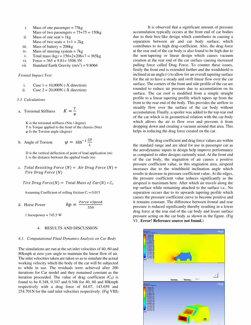
It is observed that a significant amount of pressure
accumulation typically occurs at the front end of car bodies
due to their box-like design which contributes in causing a
separation between air and car body surface, which
contributes to its high drag-coefficient. Also, the drag force
at the rear end of the car body is also found to be high due to
the non-tapering or linear design which causes vacuum
creation at the rear end of the car surface causing increased
pulling force called Drag Force. To counter these issues,
firstly the front end is extended further and the windshield is
inclined at an angle (◦) to allow for an overall tapering surface
for the air to have a steady and swift linear flow over the car
surface. The corners of the front and side profile of the car are
rounded to reduce air pressure due to accumulation on its
surface. The car roof is modified from a simple straight
profile to a linear tapering profile which tapers up from the
front to the rear end of the body. This provides the airflow to
steadily flow over the surface of the car body without
accumulation. Finally, a spoiler was added to the top rear end
of the car which is in geometrical relation with the car body
which allows the air to flow over and prevents it from
dropping down and creating a vacuum around that area. This
helps in reducing the drag force created on the car.
The drag coefficient and drag force values are within
the standard range and are ideal for use in passenger car as
the aerodynamic inputs in design help improve performance
as compared to other designs currently used. At the front end
of the car body, the stagnation of air causes a positive
pressure coefficient value, in this stagnation area, airspeed
increases due to the windshield inclination angle which
results in decrease in pressure coefficient value. At the edges,
the pressure coefficient value reduces significantly as the
airspeed is maximum here. After which air travels along the
top surface while remaining attached to the surface i.e., No
separation occurs due to its upwards tapering profile which
causes the pressure coefficient curve to become positive and
it remains constant. The difference between frontal and rear
pressure is reduced significantly thereby resulting in a lower
drag force at the rear end of the car body and lesser surface
pressure acting on the car body as shown in the figure. (Fig
VI , Error! Reference source not found.)
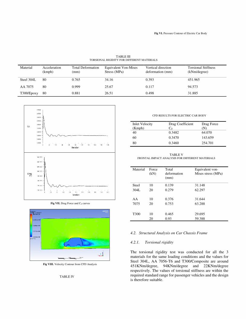
TABLE III TORSIONAL RIGIDITY FOR DIFFERENT MATERIALS
TABLE IV
CFD RESULTS FOR ELECTRIC CAR BODY
Inlet Velocity
(Kmph)
Drag Coefficient
Cd
Drag Force
(N)
40 0.3482 64.070
60 0.3470 143.659
80 0.3460 254.701
4.2. Structural Analysis on Car Chassis Frame
4.2.1. Torsional rigidity
The torsional rigidity test was conducted for all the 3
materials for the same loading conditions and the values for
Steel 304L, AA 7056-T6 and T300/Composite are around
451KNm/degree, 94KNm/degree and 22KNm/degree
respectively. The values of torsional stiffness are within the
required standard range for passenger vehicles and the design
is therefore suitable.
Material Acceleration
(kmph)
Total Deformation
(mm)
Equivalent Von-Mises
Stress (MPa)
Vertical direction
deformation (mm)
Torsional Stiffness
(kNm/degree)
Steel 304L 80 0.765 34.16 0.393 451.965
AA 7075 80 0.999 25.67 0.117 94.573
T300/Epoxy 80 0.881 26.51 0.498 31.885
Material Force
(kN)
Total
deformation
(mm)
Equivalent von-
Mises stress (MPa)
Steel 10 0.139 31.148
304L 20 0.279 62.297
AA 10 0.376 31.644
7075 20 0.753 63.288
T300 10 0.465 29.695 20 0.93 59.388
TABLE V FRONTAL IMPACT ANALYSIS FOR DIFFERENT MATERIALS
\
Fig VIII. Velocity Contour from CFD Analysis
Fig VI. Pressure Contour of Electric Car Body
Fig VII. Drag Force and Cd curves
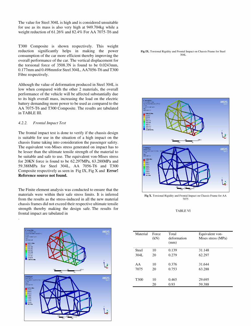
The value for Steel 304L is high and is considered unsuitable
for use as its mass is also very high at 949.704kg while a
weight reduction of 61.26% and 82.4% For AA 7075-T6 and
T300 Composite is shown respectively. This weight
reduction significantly helps in making the power
consumption of the car more efficient thereby improving the
overall performance of the car. The vertical displacement for
the torsional force of 3508.3N is found to be 0.0243mm,
0.177mm and 0.498mmfor Steel 304L, AA7056-T6 and T300
Fibre respectively.
Although the value of deformation produced in Steel 304L is
low when compared with the other 2 materials, the overall
performance of the vehicle will be affected substantially due
to its high overall mass, increasing the load on the electric
battery demanding more power to be used as compared to the
AA 7075-T6 and T300 Composite. The results are tabulated
in TABLE III. 4.2.2. Frontal Impact Test
The frontal impact test is done to verify if the chassis design
is suitable for use in the situation of a high impact on the
chassis frame taking into consideration the passenger safety.
The equivalent von-Mises stress generated on impact has to
be lesser than the ultimate tensile strength of the material to
be suitable and safe to use. The equivalent von-Mises stress
for 20KN force is found to be 62.297MPa, 63.288MPa and
59.388MPa for Steel 304L, AA 7056-T6 and T300
Composite respectively as seen in Fig IX, Fig X and Error!
Reference source not found.
The Finite element analysis was conducted to ensure that the
materials were within their safe stress limits. It is inferred
from the results as the stress-induced in all the new material
chassis frames did not exceed their respective ultimate tensile
strength thereby making the design safe. The results for
frontal impact are tabulated in
.
TABLE VI
Material Force
(kN)
Total
deformation
(mm)
Equivalent von-
Mises stress (MPa)
Steel 10 0.139 31.148
304L 20 0.279 62.297
AA 10 0.376 31.644
7075 20 0.753 63.288
T300 10 0.465 29.695 20 0.93 59.388
Fig IX. Torsional Rigidity and Frontal Impact on Chassis Frame for Steel
304L
Fig X. Torsional Rigidity and Frontal Impact on Chassis Frame for AA
7075
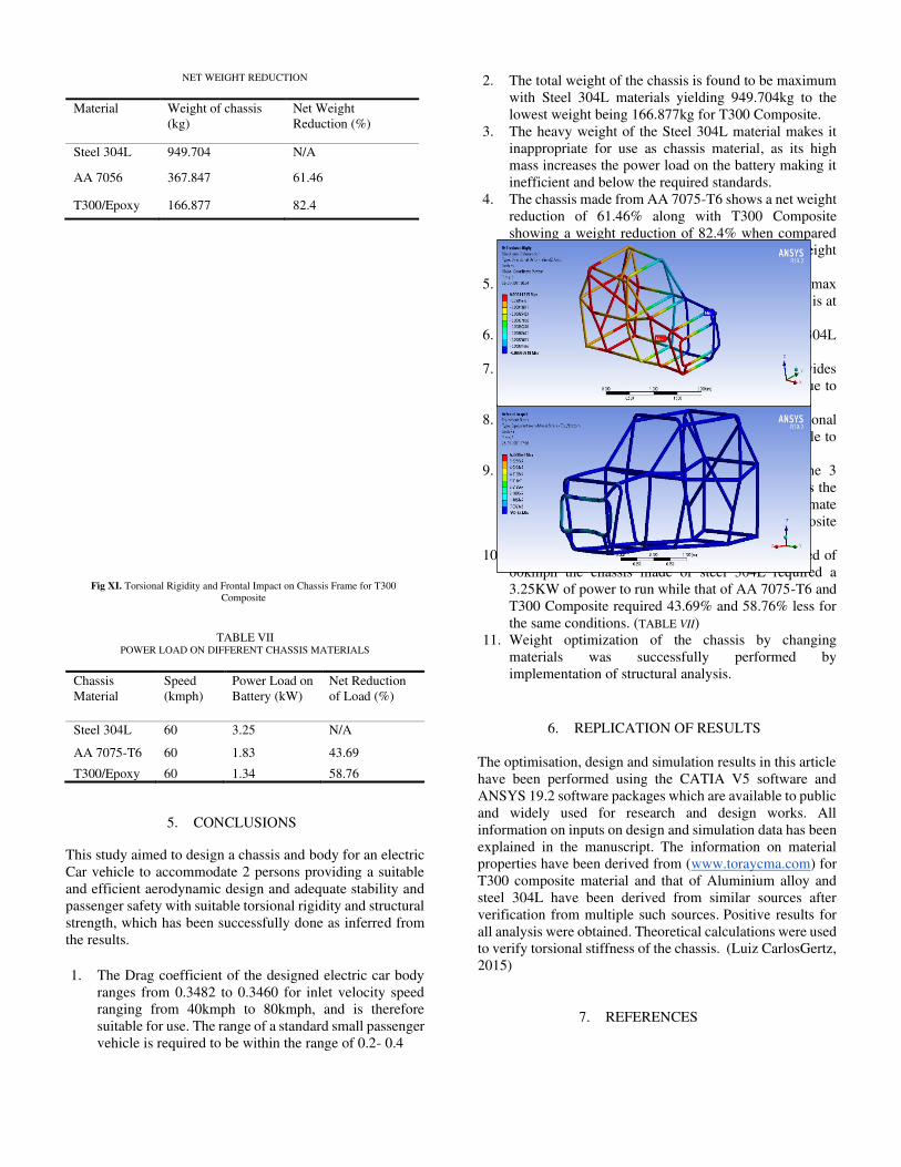
NET WEIGHT REDUCTION
Material Weight of chassis
(kg)
Net Weight
Reduction (%)
Steel 304L 949.704 N/A
AA 7056 367.847 61.46
T300/Epoxy 166.877 82.4
TABLE VII
POWER LOAD ON DIFFERENT CHASSIS MATERIALS
Chassis
Material
Speed
(kmph)
Power Load on
Battery (kW)
Net Reduction
of Load (%)
Steel 304L 60 3.25 N/A
AA 7075-T6 60 1.83 43.69
T300/Epoxy 60 1.34 58.76
5. CONCLUSIONS
This study aimed to design a chassis and body for an electric
Car vehicle to accommodate 2 persons providing a suitable
and efficient aerodynamic design and adequate stability and
passenger safety with suitable torsional rigidity and structural
strength, which has been successfully done as inferred from
the results. 1. The Drag coefficient of the designed electric car body
ranges from 0.3482 to 0.3460 for inlet velocity speed
ranging from 40kmph to 80kmph, and is therefore
suitable for use. The range of a standard small passenger
vehicle is required to be within the range of 0.2- 0.4
2. The total weight of the chassis is found to be maximum
with Steel 304L materials yielding 949.704kg to the
lowest weight being 166.877kg for T300 Composite. 3. The heavy weight of the Steel 304L material makes it
inappropriate for use as chassis material, as its high
mass increases the power load on the battery making it
inefficient and below the required standards. 4. The chassis made from AA 7075-T6 shows a net weight
reduction of 61.46% along with T300 Composite
showing a weight reduction of 82.4% when compared
to the traditional Steel 304L, are within optimum weight
range to be used as a chassis. 5. The torsional stiffness is tested for the vehicle’s max
speed of 80kmph as it is the speed at which the car is at
the risk of being unstable. 6. The values range from 415.96kNm/deg for steel 304L
to 22.11kNm/deg for T300 Composite. 7. Although the torsional stiffness of steel 304L provides
substantial stability, it is not suitable to be used due to
its high mass. 8. Both AA 7075 and T300 Composite have torsional
stiffness in the optimum range therefore are suitable to
be used in chassis. 9. The frontal impact test demonstrated that all the 3
materials are suitable for use as chassis material as the
equivalent stress values are lesser than the ultimate
strength of the materials. The stress in T300 Composite
is the least and that of AA 7075-T6 the highest. 10. After evaluation it is found that for a running speed of
60kmph the chassis made of steel 304L required a
3.25KW of power to run while that of AA 7075-T6 and
T300 Composite required 43.69% and 58.76% less for
the same conditions. (TABLE VII) 11. Weight optimization of the chassis by changing
materials was successfully performed by
implementation of structural analysis.
6. REPLICATION OF RESULTS
The optimisation, design and simulation results in this article
have been performed using the CATIA V5 software and
ANSYS 19.2 software packages which are available to public
and widely used for research and design works. All
information on inputs on design and simulation data has been
explained in the manuscript. The information on material
properties have been derived from (www.toraycma.com) for
T300 composite material and that of Aluminium alloy and
steel 304L have been derived from similar sources after
verification from multiple such sources. Positive results for
all analysis were obtained. Theoretical calculations were used
to verify torsional stiffness of the chassis. (Luiz CarlosGertz,
2015)
7. REFERENCES
Fig XI. Torsional Rigidity and Frontal Impact on Chassis Frame for T300
Composite
1. Evangelos Ch. Tsirogiannis, G. E. (2019). Electric Car
Chassis for Shell Eco Marathon:Design, Modelling and
Finite Element. World Electric Vehicle Journal. 2. Georgios Koumartzakis, P. S. (2018). design and
development of protype electric vehicle chassis. 7th
BETA CAE International Conference.
3. H Ahmad, A. A. (2020). A review of carbon fiber
materials in automotive industry. IOP Conf. Series:
Materials Science and Engineering.
4. Hc, A. (1993). Chassis Engineering.
5. Louis Cattafesta, C. B. (2010). Fundamentals of Wind-
Tunnel Design. Encyclopedia of Aerospace
Engineering,.
6. Luiz CarlosGertz, A. C. (2015). Chassis Design for
Electric Car Prototype. SAE Brazil.
7. R.K. Kawade, M. N. (2017). Chassis Frame Torsional
Stiffness Analysis. International Journal for Scientific
Research & Development.
8. Steven Tebby, E. E. (2011). Methods to Determine
Torsion Stiffness in an Automotive Chassis. Computer-
Aided Design & Applications, PACE (1).
9. Tamer Nabil*, A.-B. H. (2020). Experimental Approach
and CFD Simulation of Battery Vehicle. International
Journal of Fluid Mechanics & Thermal Sciences.