Embed Size (px)
Citation preview

1
Submitted, accepted and published by:
Applied Energy 157 (2015) 295–303
Design and operation of a 50 kWth Chemical Looping Combustion
(CLC) Unit for Solid Fuels
Alberto ABAD*, Raúl PÉREZ-VEGA, Luis F. de DIEGO, Francisco GARCÍA-
LABIANO, Pilar GAYÁN, Juan ADÁNEZ
Instituto de Carboquímica (ICB-CSIC), Miguel Luesma Castán 4, E-50018 Zaragoza, Spain
*Corresponding Author: [email protected]
Abstract
A Chemical Looping Combustion (CLC) unit for solid fuels has been designed, erected and
operated. The design was based on a thermal power of 20 kWth for in-situ Gasification
Chemical Looping Combustion (iG-CLC) or 50 kWth for Chemical Looping with Oxygen
Uncoupling (CLOU). Fuel and air reactors are two interconnected circulating fluidized beds
reactors, with the coal being fed at the bottom of the fuel reactor to maximize the contact
between the volatile matter and the oxygen carrier particles. A carbon stripper has been
included between fuel and air reactors to increase the CO2 capture rates. In this unit, the char
particles are separated from the oxygen carrier particles and recirculated to the fuel reactor.
The solids flow exiting from the fuel reactor is split into two different streams by using a
double loop seal down the fuel reactor cyclone. One goes to the carbon stripper and the other
is recirculated to the fuel reactor. In this way it is possible to have an independent control of
solids inventory in the fuel reactor and the global solid circulation flow rate between fuel and
air reactors. First operational results at steady state have been obtained with stable operation
in iG-CLC mode during combustion of a bituminous coal with ilmenite being the oxygen

2
carrier. A CO2 capture value of 88% at 991 ºC and a total oxygen demand value of 8.5% were
obtained with a solids inventory in the fuel reactor of 470 kg/MWth.
Keywords: CO2 capture; CLC; CLOU; Coal; Design.
1 Introduction
In Chemical Looping Combustion (CLC) with solid fuels, the fuel is physically mixed with
the oxygen carrier. A scheme of the CLC with solid fuels is shown in Fig. 1. The oxygen
needed for fuel combustion is supplied by an oxygen carrier, normally a metal oxide, which
circulates between the so-called fuel and air reactors. In the fuel reactor, the fuel is oxidized to
CO2 and H2O, which facilitates CO2 capture once the water has been condensed. The reduced
oxygen carrier is then transported to the air reactor where it is re-oxidized before starting a
new cycle. The net chemical reaction and combustion enthalpy is the same as in conventional
combustion. CO2 capture is inherent to this process, as the air is not mixed with the fuel.
Significant advances have been made in the development of CLC using solid fuels in recent
years by means of two processes: in-situ gasification CLC (iG-CLC) and Chemical Looping
with Oxygen Uncoupling (CLOU) [1,2].
Fig. 1. Reactor scheme of CLC processes with solid fuels.
In the iG-CLC concept coal is fed directly to the fuel reactor and mixed with the oxygen
carrier. Steam and/or recycled CO2 are supplied to the fuel reactor as fluidizing agents. In-situ
N2 + O2
Air
H2O (l)
Airreactor
Fuelreactor
Coal
CO2
CO2 + H2O
Carbonstripper
Ash
H2O (v)
CO2
MexOy
MexOy-1
H2O (v)

3
gasification of coal occurs, generating volatile matter and gasification products, which are
oxidized by gas-solid reactions with the oxygen carrier. Gasification is the limiting step for
coal conversion. The slow coal gasification rate may cause that the solids stream exiting from
the fuel reactor contained some unconverted char together with the oxygen carrier and ash.
Once the unconverted char reaches the air reactor it is burnt with air to produce CO2, which
could significantly decrease the CO2 capture efficiency of the process. To increase the
residence time of char particles in the fuel reactor, without excessively increasing the reactor
size, a carbon separation unit is included after the fuel reactor. This unit can be designed as a
carbon stripper, where char particles are separated from the oxygen carrier particles and
recirculated to the fuel reactor using their different fluidization properties. In addition,
complete combustion of gases from the fuel reactor has not been reached in existing iG-CLC
units. Some strategies have been proposed to convert the unburnt compounds. They include
an oxygen polishing step to complete gas combustion, the separation and recirculation of
unburnt compounds or a secondary fuel reactor in series [3].
The CLOU concept was developed based on the use of oxygen carrier materials which can
release gaseous oxygen and thereby allow the solid fuel to be burnt with gas phase oxygen
[4]. These materials can also be regenerated at high temperatures. Complete combustion and
CO2 capture rates close to 100% have been found in a 1.5 kWth CLOU unit due to the fast
combustion of coal with gaseous oxygen generated in-situ in the fuel reactor [5].
To date, several design concepts have been developed for iG-CLC ranging from 10 kWth to 3
MWth units, but no operation at scale higher than 1.5 kWth have been reported for CLOU [1].
Major differences between CLC systems were found in the fuel reactor design. In some cases,
the fuel reactor included a bubbling- or spout-fluid bed [6-8]; but in other cases, a fuel reactor
at the high velocity fluidization regime is preferred [9-11]. Thus, the cross-sectional area per
power unit is minimized. Among the latter, a 100 kWth unit [9] allowed stable operation with
ilmenite and CO2 capture rate values close to 100% were obtained because of the high

4
efficient carbon stripper included [12]. CO2 capture rates of 97-98% were obtained. However,
the combustion efficiency in the fuel reactor was about 80-85%, due to a low solids inventory
in the fuel reactor (300-400 kg/MWth), which results in a relevant fraction of unconverted
gases in the fuel reactor. Note that theoretical calculations recommended values ranging from
750 to 1500 kg/MWth in order to have a trade-off between combustion efficiency and ilmenite
inventory [12-14]. The solids inventory in the fuel reactor and the solids circulation rate is
uncoupled by using a circulation riser. However, a relatively high steam flow is required in
the carbon stripper and the circulation riser, which result in high values, between 3 and 4, of
steam to fixed carbon ratio.
Two different CLC units have been operated at the MWth scale. A 1 MWth unit [10] was
designed for solids inventory values about 200-300 kg/MWth. The solids circulation flow rate
between the air and fuel reactors could be modified by means of a screw conveyor attached to
the loop seal below the air reactor cyclone. Later, the screw conveyor was replaced by an L-
valve [15]. Thus, the amount of solids in the fuel reactor would be directly linked to the solids
circulation rate. During preliminary operation, steam to fixed carbon ratio was about 2.
Another CLC unit, 3 MWth, [11] was characterized by a direct hydraulic link between the
bottom of fuel and air reactors. The hydraulic link allowed high CO2 capture rates to be
achieved without the necessity of a carbon stripper. This system is similar to that found in a
120 kWth CLC unit for gaseous fuels [16], where the amount of solids in the fuel and air
reactors were closely dependent on the gas velocity and the solids circulation flow rate.
The objective of this work was to design and built a flexible CLC unit for solid fuels, which
could be operated at 20 kWth in iG-CLC and 50 kWth in CLOU mode. The design of the
concept is based on two interconnected circulating fluidized beds reactors. Independent
control of solids circulation flow rate and solids inventory in the fuel and air reactors is
intended with the proposed design. Thus, direct relation between operational conditions and
performance of the CLC unit could be easily evaluated. This unit allows investigating the

5
performance of the iG-CLC and CLOU processes burning different fuels (lignite, bituminous
coal and biomass) using different oxygen carrier materials (Fe-based minerals or copper-
based oxygen carrier). Preliminary results obtained during combustion of a bituminous coal
with ilmenite by iG-CLC are presented showing carbon capture efficiencies and oxygen
demands.
2 Design of the 50 kWth CLC unit
2.1 Introduction to design
A layout of the CLC unit for solids fuels is shown in Fig. 2. It is based on two interconnected
circulating fluidized bed reactors, the air and fuel reactors, and a carbon stripper, being a
bubbling fluidized bed. The carbon stripper improves the carbon capture efficiency by
recovering char particles that escape from the fuel reactor. The design includes a double loop
seal after the fuel reactor cyclone to split the solids stream before reaching the carbon stripper.
A fraction of solids is allowed to go to the carbon stripper but another fraction is recycled to
the riser of the fuel reactor. In this way it is possible to reach one independent control of solid
circulation in fuel reactor from the global solid circulation flow. Moreover, the measurement
of solids circulation between fuel and air reactors can be performed by means of two diverting
solid devices located below the cyclones.
Ilmenite (dp=0.17 mm; ρp=3710 kg/m3) and a Cu-based material (60 wt.% CuO and 40 wt.%
MgAl2O4; dp=0.17 mm; ρp =3860 kg/m3) were considered as oxygen carriers for iG-CLC and
CLOU, respectively; while a South African bituminous coal (dp=0.10 mm; ρp =1000 kg/m3)
was assumed the solid fuel for design calculations. The oxygen carriers have been
successfully tested in continuously operated iG-CLC [9,17-20] and CLOU units [5,21-23].
For design conditions, the nominal thermal power was 20 kWth for iG-CLC mode and 50
kWth for CLOU mode. The difference of nominal power is because the better performance of
CLOU with respect to iG-CLC on the basis of CO2 capture and combustion efficiency

6
[24].The solids inventory in the fuel reactor was set to 20 kg in iG-CLC, corresponding to
1000 kg/MWth. This solids inventory value was estimated as the amount of oxygen carrier to
balance the trade-off between the increase of pressure drop and the decrease in oxygen
demand caused by an increase of solids in the reactor [12,14]. In CLOU, the same amount of
solids corresponded to 400 kg/MWth, which has been considered a suitable value from
previous works [5, 24-26].
Fig. 2. Layout of the 50 kWth CLC Plant facility at ICB-CSIC-s50
Different types of coals, ranging from lignite to anthracite, as well as biomass, can be used as
fuel. Mass balances, fluid dynamics considerations and the performance of the fuel reactor
predicted by a theoretical model previously developed [13] were taken into account for the
design of the CLC unit. The solids circulation flow rate, reactor temperatures, solids inventory
in the fuel reactor, steam requirements and air flow were determined. Design of the carbon
stripper, loop seals, and the cyclone system was also considered.

7
The design was done on the basis of the operation both in iG-CLC and CLOU modes. The
solid fuel feeding point was just above the distributor plate in the fuel reactor. It is intended to
convert the fuel to CO2 and H2O, minimizing the unburnt compounds. To maximize the solid
fuel conversion, the fuel reactor temperature was assumed to be 1000 ºC in iG-CLC [9, 12-14,
17] and 950 ºC in CLOU [5, 21,23]. The CLC unit is not expected to be auto-thermal due to
heat losses associated with the unit size. The fuel reactor, air reactor, carbon stripper, and loop
seals are electrically heated by independent furnaces.
2.2 Design parameters
The dimensions of the reactor are defined by the design values of the pressure drop, solids
inventory and gas velocity. Design data are shown in Table 1. The cross sectional area
corresponded to 0.39 m2/MWth in iG-CLC and 0.16 m2/MWth in CLOU.
Table 1. Main design parameters of the 50 kWth Unit
Operation mode iG-CLC CLOU
Power (kWth) 20 50
Reactor FR AR CS FR AR CS
Height (m) 4.15 4.80 0.71 4.15 4.80 0.71
Diameter (cm)* 10.2/8.1 30.0/10.2 15.0 10.2/8.1 30.0/10.2 15.0
Solids inventory (kg) 20 55 8 20 55 8
P (kPa) 25 15 4.5 25 15 4.5
ug,in (m/s) 1.0 0.40 0.35 1.0 0.90 0.35
ug,out (m/s) 4.00 4.00 0.35 5.50 9.00 0.35
Stoichiometric GS, FR (kgm-2s-1) 7.5 - - 12.5 - -
Designed GS,FR (kgm-2s-1) 30 11 - 50 18 -

8
* bottom part/upper part
2.2.1 Fuel reactor and Double loop seal
The fuel reactor can be fluidized by H2O, CO2 or mixtures of these gases. The gas flow fed to
the bottom part of the fuel reactor was fixed in order to operate with a gas velocity in the
bottom bed just above the terminal velocity of oxygen carrier particles; see Fig. 3 [27]. When
the gases from coal conversion together with the gas stream from the carbon stripper were
considered, the gas velocity was estimated to be 4 m/s in iG-CLC and 5.5 m/s in CLOU.
Under these conditions, the solids flux to the fuel reactor cyclone was estimated to be 30
kgm-2s-1 in iG-CLC and 50 kgm-2s-1 in CLOU [16], which are higher values than those
required for stoichiometric conditions, i.e. 7.5 kgm-2s-1 in iG-CLC and 12.5 kgm-2s-1 in
CLOU. Stoichiometric conditions were defined by a value of the oxygen carrier to fuel ratio
= 1. The parameter was defined as the flow of oxygen available in the circulating solids
stream divided by the flow of oxygen required to achieve complete fuel combustion.
The maximum oxygen carrier to fuel ratio achievable in the CLC unit was estimated to be =
4. However, values between 1 and 2 are preferable to maximize the CO2 capture rate. For
design conditions was selected to be 2, which means that the solids circulation flow to the
air reactor must be lower than the solids flow exiting the fuel reactor. Thus, the double loop
seal (LS-D) must be operated to direct the solids circulation towards the carbon stripper, and
subsequently to the air reactor, at the desired value. The LS-D system is designed in order to
divide the solids stream from the fuel reactor cyclone in two: (1) solids to the carbon stripper,
and then to the air reactor, in order to fulfill the required solids circulation flow rate between
air and fuel reactors; and (2) excess of solids was recirculated to the fuel reactor. In this way,
the residence time of solids, including unconverted char particles, is maximized whereas the
solids circulation flow rate between the air and fuel reactors was guaranteed. The use of a

9
double loop seal was considered to be an improvement with respect to existing CLC units for
solid fuels. Another important feature is the possibility to have a direct measurement of the
solids flux exiting from both the fuel and air reactors by means of the respective solids
circulation measurement devices.
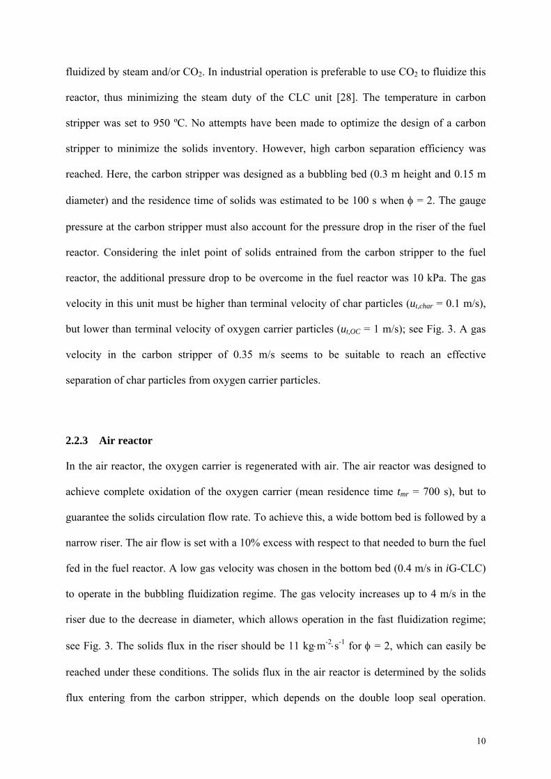
Fig. 3. Fluidization regime in the flow map adapted from [27]. u* = Re/Ar1/3; dp* = Ar1/3
2.2.2 Carbon stripper
The carbon stripper separates the unconverted char particles from the oxygen carrier
according to their different fluid dynamic properties. Char particles are lighter and smaller
than oxygen carrier particles and can be elutriated from the carbon stripper and recirculated to
the fuel reactor using an appropriate fluidization flow, whereas the oxygen carrier particles
are left to pass to the air reactor via loop seal LS-CS. Char particles are recirculated to the
bottom bed of the fuel reactor, well above the distributor plate. The carbon stripper can be
10‐3
10‐2
10
1
10‐1
1 10 102
dp*
u*
umf
ut
Bubbling
Spouted
Turbulent
Pneumatictransport Fast
fluidization
FuelReactor
Air Reactor(up)
CarbonStripper
bottomup
Air Reactor(bottom)
10
fluidized by steam and/or CO2. In industrial operation is preferable to use CO2 to fluidize this
reactor, thus minimizing the steam duty of the CLC unit [28]. The temperature in carbon
stripper was set to 950 ºC. No attempts have been made to optimize the design of a carbon
stripper to minimize the solids inventory. However, high carbon separation efficiency was
reached. Here, the carbon stripper was designed as a bubbling bed (0.3 m height and 0.15 m
diameter) and the residence time of solids was estimated to be 100 s when = 2. The gauge
pressure at the carbon stripper must also account for the pressure drop in the riser of the fuel
reactor. Considering the inlet point of solids entrained from the carbon stripper to the fuel
reactor, the additional pressure drop to be overcome in the fuel reactor was 10 kPa. The gas
velocity in this unit must be higher than terminal velocity of char particles (ut,char = 0.1 m/s),
but lower than terminal velocity of oxygen carrier particles (ut,OC = 1 m/s); see Fig. 3. A gas
velocity in the carbon stripper of 0.35 m/s seems to be suitable to reach an effective
separation of char particles from oxygen carrier particles.
2.2.3 Air reactor
In the air reactor, the oxygen carrier is regenerated with air. The air reactor was designed to
achieve complete oxidation of the oxygen carrier (mean residence time tmr = 700 s), but to
guarantee the solids circulation flow rate. To achieve this, a wide bottom bed is followed by a
narrow riser. The air flow is set with a 10% excess with respect to that needed to burn the fuel
fed in the fuel reactor. A low gas velocity was chosen in the bottom bed (0.4 m/s in iG-CLC)
to operate in the bubbling fluidization regime. The gas velocity increases up to 4 m/s in the
riser due to the decrease in diameter, which allows operation in the fast fluidization regime;
see Fig. 3. The solids flux in the riser should be 11 kgm-2s-1 for = 2, which can easily be
reached under these conditions. The solids flux in the air reactor is determined by the solids
flux entering from the carbon stripper, which depends on the double loop seal operation.

11
Higher velocities are required in CLOU, 0.9 m/s in the bottom bed and 9 m/s in the riser,
because the unit is designed for a higher thermal power in this mode.
2.2.4 Cyclones and Loop seals
Solids entrained from the air and fuel reactors are separated by respective cyclones and sent to
the next element in the CLC unit. The dimensioning of the cyclone is based on a high
efficiency standard cyclone with a gas velocity at the cyclone inlet of 15 m/s [29].
Loop seals were included in order to balance the pressure between two connected elements.
Thus, the length of the low pressure side of each loop seal is determined by the pressure
balance in the system, as shown in Fig. 4. The LS-D must balance an overpressure of 10 kPa
in the fuel reactor inlet point from the carbon stripper with respect to the fuel reactor cyclone
exit. LS-CS must balance a low pressure difference between the bottom of the air reactor and
the upper part of the carbon stripper. LS-AF was carefully designed to balance a high pressure
difference between the air reactor cyclone and the bottom part of the fuel reactor, which is 25
kPa. The difference of pressure between both sides of each loop seal must be compensated by
a solids column in the side with lower pressure, which must be at least 0.8, 0.4 and 2.0 m for
loop seals LS-D, LS-CS and LS-AF, respectively. Estimated pressure drops in each element
of the CLC unit for the design conditions can be calculated following continuous lines in Fig.
4.
The final objective of using the loop seals was to avoid the gas mixing between reactors
connected by the loop seal and to guarantee the appropriate flow of solids. Thus, loop seal
LS-CS avoids the mixing of air and H2O-CO2 in the carbon stripper, whereas loop seal LS-AF
hinders the mixing of air and gases from fuel. Loop seal LS-D is necessary to avoid leakage
of gas from the carbon stripper to the fuel reactor cyclone. Moreover, this loop seal controls
the circulation flow rate of solids between the fuel and air reactors.
The loop seal units were designed as bubbling fluidized beds and were dimensioned to allow
a high solids circulation flow rate, i.e. the loop seal must not limit the solids circulation flow

12
rate. The required solid flux in the loop seals is 16 kgm-2s-1 at the oxygen carrier to fuel ratio
= 2, whereas the maximum capacity may be as high as 300 kgm-2s-1 [30].
Fig. 4. Estimated pressure profile in the CLC unit. Dotted lines are elements connected for
different loop seals. Continuous lines are pressure versus height in each element.
Note that the pressure at the reactor inlets should account for an additional pressure drop of
30% due to the presence of a distributor plate in the fluidized beds. Finally, the heights of air
and fuel reactors were determined in order to arrange all the elements of the CLC unit,
including the required column of solids in the loop seals. The air reactor height is 4.65 m and
the fuel reactor is 4.0 m tall.
‐0.5
0.0
0.5
1.0
1.5
2.0
2.5
3.0
3.5
4.0
4.5
5.0
0 10 20 30 40
Height (m
)
Gauge pressure (kPa)
FR‐in
Cyc‐FR
Cyc‐AR
AR‐in
LS‐CS
CS‐in
LS‐D
LS‐AF

13
2.3 Relevant parameters in evaluation of coal combustion in the CLC unit
The evaluation of the iG-CLC unit was done based on carbon and oxygen balances. Carbon in
the fuel can be released in volatile matter, gasified in the fuel reactor, burnt in the air reactor,
or elutriated in unconverted char particles escaping from the fuel reactor cyclone. The
elutriated char flow (FC,elut) has been defined as the difference between the carbon feeding
into the fuel reactor and the carbon in the fuel and air reactor exhaust gas streams; see Eq. 1.
2 4 2,
SF SFC elutr CO CO CH COoutFR outAR
C
m CF F F F F
M
(1)
The fraction of carbon in coal converted both in the fuel and air reactor is evaluated by means
of the solid fuel conversion ( SF ), which can be calculated by means of Eq. 2.
4 2 2CH CO CO COoutFR outAR
SF
SF SF C
F
m C M
F F F
(2)
The solid fuel conversion is the relation between the total flow of gaseous carbon leaving both
fuel and air reactors and the total flow of carbon fed into the fuel reactor from solid fuel. Un-
converted carbon in the iG-CLC unit was elutriated in partially converted char particles.
To evaluate the performance of the iG-CLC operation, relevant parameters are used in
accordance to previous works [3, 12-14, 18-20, 24, 31,32].
The CO2 capture efficiency ( CC ) has been defined as the fraction of the carbon introduced
that is converted to gas in both the fuel and air reactors (Eq. 3).
2 4
2 4 2
CO CO CH outFRCC
CO CO CH COoutFR outAR
F F F
F F F F
(3)
The CO2 captured in the unit is the addition of the carbon contained in the volatile matter and
the carbon from char gasification. Therefore, the CO2 capture efficiency calculated according
Eq. (3) depends on the fraction of char that has been gasified.

14
The char conversion in the fuel reactor ( ,Char FRX ) is defined as the fraction of fixed carbon
converted to gas in the fuel reactor. The calculation of the char conversion was corrected to
consider the elutriated char, i.e. the fraction of char particles that was not recovered by the
fuel reactor cyclone; see Eq. 4. Thus, the denominator in Eq. 4 was calculated as the fixed
carbon in coal discounting the elutriated char. In this way, a proper evaluation of the char
conversion potential in the fuel reactor can be done, as it was previously described [31,32] by
considering only the amount of char having the chance to be converted in the CLC unit.
2 4 ,
,, ,
CO CO CH C voloutFRChar FR
C fix C elutr
F F F FX
F F
(4)
The volatile matter carbon flow was calculated from the ultimate and proximate analysis of
the coal as the difference between the total carbon and the fixed carbon; see Table 2.
Besides the coal gasification, the fuel reactor must oxidize the gasification products to CO2
and H2O. The conversion of gasification products was evaluated by means of two parameters:
the combustion efficiency in the fuel reactor, c,FR, and the total oxygen demand, T. The
combustion efficiency in the fuel reactor was defined as the fraction of oxygen demanded by
the coal converted in the fuel reactor, i.e. volatile matter and gasification products, that is
supplied by the oxygen carrier in the fuel reactor:
4 2
2
,
, ,
41
2
CH CO H outFRc FR
SF SF O CO outAR C elut
F F F
m M F F
(5)
The combustion efficiency in the fuel reactor is related to the oxygen demand, OD, defined
by other authors by c,FR = 1 – OD [9,17].
Finally, the total oxygen demand, T , is defined as the fraction of stoichiometric oxygen
required to fully oxidize the unconvertered gases exiting the fuel reactor to CO2 and H2O with
respect to the stoichiometric oxygen demanded by the solid fuel fed.

15
4 2
4 CH CO H outFRT
SF SF O
F F F
m M
(6)
2.4 Mathematical predictions in the 50 kWth CLC unit for solid fuels
The performance of the CLC unit with coal as fuel was simulated by using theoretical models
for iG-CLC and CLOU previously developed and validated against experimental results in
100 kWth iG-CLC and 1 kWth CLOU units [12, 25]. “El Cerrejón” Colombian bituminous
coal was assumed to be the fuel, which was used in previous experimental works [24]. Fig. 5
shows the CO2 capture efficiency and the oxygen demand predicted in the CLC unit as a
function of the carbon stripper efficiency separating unconverted char particles from the
oxygen carrier stream. The oxygen demand was defined as the ratio of oxygen flow required
to fully oxidize unconverted gases from the fuel reactor to the stoichiometric oxygen flow for
complete coal combustion.
Because of the slow rate of coal gasification, a highly efficient carbon stripper is key to
reaching high CO2 capture rates in iG-CLC mode. Moreover, complete combustion was not
predicted in the fuel reactor. The total oxygen demand increases as the fuel conversion in the
fuel reactor increases due to the increase of the char conversion with the carbon stripper
efficiency. Thus, a greater amount of gases is produced in the fuel reactor by char
gasification. Assuming the conversion of volatile matter was roughly the same regardless the
char converted, the increase in the T is due to a higher amount of gasification products to be
oxidized as the carbon stripper efficiency increased. Therefore, an increase in the carbon
stripper efficiency will increase the total oxygen demand [14]. The total oxygen demand
predicted in iG-CLC increased from 3% to 10% when the carbon stripper efficiency increases
from 0 to 1.
The estimated CLOU performance was much better than that predicted for iG-CLC. Complete
combustion was predicted even when the fuel power was higher (50 kWth) compared to the

16
value assumed for iG-CLC (20 kWth). The fast coal conversion in CLOU via combustion with
gaseous oxygen evolved from the oxygen carrier makes it possible to achieve CO2 capture
rates greater than 95% even if poor carbon stripper performance was assumed. These
predicted differences between iG-CLC and CLOU agree with results previously described
from experimental works in a 1 kW CLC unit [24].
Fig. 5. Estimated CO2 capture, CC, and total oxygen demand, T, in the CLC unit for: (a) 20
kWth in iG-CLC mode; and (b) 50 kWth in CLOU mode.
3 Performance during coal combustion in iG-CLC mode
3.1 Materials used and experimental procedure
An experimental campaign in this CLC unit was conducted using ilmenite as oxygen carrier
and a South African bituminous coal. Ilmenite particles diameter was +0.1-0.3 mm. Table 2
shows the main characteristics of coal used, which was ground and sieved in order to use
particles in the 0.1-0.3 mm interval. The proximate and ultimate analyses of coal were
obtained using stabilized coal exposed to the atmosphere. Stabilized coal was the same which
was used in the experiments. In this way, the humidity of the coal was not varied during the
experiments carried out for several days.
0
10
20
30
40
50
60
70
80
90
100
0.0 0.2 0.4 0.6 0.8 1.0
Oxygen dem
and and CO
2Cap
ture (%)
Carbon Stripper Efficiency (‐)
(a) iG‐CLC
CO2 capture
Oxygen demand
0
10
20
30
40
50
60
70
80
90
100
0.0 0.2 0.4 0.6 0.8 1.0
Oxygen dem
and and CO
2Cap
ture (%)
Carbon Stripper Efficiency (‐)
(b) CLOU
CO2 capture
Oxygen demand

17
Table 3 shows the main operating conditions used in the CLC unit. The temperatures of the
fuel reactor and carbon stripper were varied while the temperature of the air reactor was
maintained at about 950 ºC. In addition, pressure drop in fuel reactor for test 1 was higher
than for tests 2-4, which was related to a higher amount of solids with the temperature drop.
The fuel reactor and carbon stripper were fluidized with steam, although N2 was used in the
loop-seals. The coal feed rate and solids circulation rate were 1.8 and 101 kg/h, respectively,
during all tests. These values corresponded to a thermal power of 12.5 kWth and an oxygen
carrier to fuel ratio of = 1.1.
Table 2. Main characteristics of coal (stabilized humidity by exposition to the atmosphere).
South African bituminous coal (wt.% raw matter)
Proximate analysis
Moisture 3.5
Volatile matter 25.5
Ash 15.7
Fixed carbon 55.3
Ultimate analysis
C 66.3
H 3.6
N 1.8
S 0.5
Oa 8.6

18
LHV (kJ/kg) 24930
ΩSF (kg O/kg solid fuel) 2.0
a Oxygen by difference
Table 3. Operating conditions in iG-CLC unit.
Test 1 2 3 4
Fuel Reactor
FRT (ºC) 905 963 970 991
FRP (kPa) 11.8 9.3 8.9 8.3
,OC FRm (kg/MWth) 680 535 506 466
,g inFRu (m/s) 1.0 1.1 1.1 1.1
,g outFRu (m/s) 4.3 4.6 4.6 4.7
Air Reactor
ART (ºC) 937 943 945 950
ARP (kPa) 3.1 3.2 3.2 3.2
,g inARu (m/s) 0.9 0.9 0.9 0.9
,g outARu (m/s) 6.9 6.8 6.9 6.9
Carbon Stripper
CST (ºC) 900 955 957 969
,g inCSu , in (m/s) 0.34 0.35 0.35 0.36

19
3.2 Results and discussion
Fig. 6 shows the evolution of the temperatures and gas concentrations in both the fuel and air
reactors during heating and start-up until steady state was reached for the operating conditions
of Test 4; see Table 3. During initial electrical heating all reactors were fluidized with air.
After the desires temperatures in the fuel and air reactors were reached, the fluidizing gas was
changed to steam in both the fuel reactor and carbon stripper. Then the coal feeding into the
fuel reactor was started and the combustion by iG-CLC began. Steady operation was quickly
reached, with roughly constant concentration values of CO2, CO, H2 and CH4.
Fig. 6. Evolution of temperatures and gas concentrations in both fuel and air reactors during
Test 4.
Gas
co
nce
ntr
atio
n (
vol.
%,
dry
, N
2 f
ree)
0
20
40
60
80
100
Tem
pe
ratu
re (
ºC)
0
200
400
600
800
1000
Time (min)
0 100 200 300
0
5
10
15
20
25
0
200
400
600
800
FR
AR
CO2
CO
CH4
CO2
O2
Temperature
Temperature
Heating period Coal combustion
H2
Gas
co
nc
entr
atio
n (
vol.
%)

20
Table 4 shows the main relevant results obtained in the iG-CLC during the South African coal
combustion. Fig. 7 shows the CO2 capture and total oxygen demand values according to the
Tests summarized in Table 4.
The solid fuel conversion was very similar with values between 80 and 87% during all tests.
The CO2 capture values increased when the temperature increased reaching a value of 88%
when the fuel reactor temperature was 991ºC. Thus, the fuel reactor temperature has a high
impact on the char conversion, even more considering that the solids inventory in the fuel
reactor decreased when the temperature increased; see Table 3. The char conversion into the
fuel reactor increased from 51% at 905 ºC to 84.7% at 991 ºC. It is believed that the effect of
the decrease in the solids inventory with temperature (see Table 3) is of lower relevance than
the effect of the increase in the temperature, especially for tests 2, 3 and 4. Likely, a lower gas
flow in test 1 at 905ºC, due to a lower fuel conversion, allowed a higher amount of solids in
the fuel reactor.
Table 4. Main relevant parameters in iG-CLC
Test 1 2 3 4
CC (%) 60.7 79.4 81.3 87.6
SF (%) 83.9 82.0 80.1 87.0
CharX (%) 51.0 74.1 76.5 84.7
,c FR (%) 86.6 89.3 89.5 89.2
T (%) 7.7 7.5 7.4 8.6

21
Fig. 7. CO2 capture, CC , and total oxygen demand, T , values during combustion of South
African bituminous coal in iG-CLC mode.
The total oxygen demand remained practically constant at about of 7.5%. At 991 ºC, the value
increased one point likely due to the lower solid inventory in the fuel reactor and the higher
amount of gasification products to be oxidized. Values of total oxygen demand are even lower
than those obtained with ilmenite in a CLC unit with the fuel reactor being operated in the
bubbling fluidization regime, where most of unconverted gases came from volatile matter [3,
18-20]. Assuming CH4 was only formed during devolatilization [33], a mass balance to CH4
gave a value of the CH4 conversion of around 70%. CH4 was the most difficult compound to
convert by the oxygen carrier because of its low reactivity with ilmenite, and it accounts for a
50 % of the total oxygen demand in exhaust gases during tests 1-4. This suggests an improved
conversion of volatile matter in the dilute region above the dense bed in the fuel reactor of the
50 kWth CLC unit, which operated in the turbulent fluidization regime; see Fig. 3.
The results shown for the first tests carried out in the unit was successful. Low values of
oxygen demand were obtained due to the combination of fuel reactor operation in turbulent
fluidization regime together the use of a solids inventory around 500 kg/MWth in most of
cases. The total oxygen demand obtained was lower than those obtained in other CLC units
Temperature FR (ºC)
900 930 960 990
CO
2 C
aptu
re (
%)
0
20
40
60
80
100
To
tal O
xyge
n D
em
and
(%
)
0
5
10
15
20
25
30
35
40
CC
T

22
with ilmenite being the oxygen carrier [3]. In addition, the oxygen demand would be
decreased by increasing the solids inventory above 500 kg/MWth. An optimum value of the
solids inventory considering the balance between the increase in the pressure drop and the
improvement on combustion efficiency was estimated to be about 700-1000 kg/MWth [12-14].
The CO2 capture rate increased with fuel reactor temperature, and a value of 88% at 991ºC
was found. This value could be increased by increasing fuel reactor temperature or optimizing
operation in carbon stripper; see Figure 5. Nevertheless, the efficiency of the carbon stripper
could not be calculated at this time. Theoretical simulations can be used in order to estimate
the efficiency of the carbon stripper [12]. When comparing the total oxygen demand for the
same results of CO2 capture rate, i.e. 85% at 990ºC, we obtained T = 7.5% in the
experiments and T = 7.3% from predictions in Figure 5, which was a good agreement. For
this case, the predicted carbon stripper efficiency was 96%.
Thus, from results obtained in this work is recommended for industrial application a solids
inventory higher than 500 kg/MWth to reduce the total oxygen demand of the process, and a
high temperature in the fuel reactor (close to 1000ºC) as well as a highly efficient carbon
stripper to improve the CO2 capture rate [34]. Considering the required cross-section area and
pressure drop in the fuel reactor, the proposed design will allow the operation with the
recommended solids inventory [28]. Also, a double loop seal, which was used to control the
flow of solids to the carbon stripper and air reactor, is an extended technology in the industry
to split a flow of solids.
Future work will be performed in order to optimize coal conversion in the iG-CLC operation
by improving the carbon stripper operation and by increasing the amount of solids in the fuel
reactor. Also, operation in CLOU mode is planned using an oxygen carrier with oxygen
uncoupling property, e.g. based on copper or manganese.

23
4 Conclusions
A CLC unit for solid fuels was designed to operate in both iG-CLC and CLOU modes. The
unit includes a fuel reactor, an air reactor and a carbon stripper. The use of a double loop seal
below the fuel reactor cyclone allows the solids circulation flow rate to be controlled
independently of the solids inventory in the fuel reactor. Initial experiments carried out by iG-
CLC burning a bituminous coal with ilmenite showed high CO2 capture efficiencies with low
oxygen demands for the gases coming from the fuel reactor, in accordance with a model
developed for this system. The fuel reactor temperature strongly influenced char conversion,
increasing the CO2 capture when temperature was increased. Oxygen demand was barely
affected by fuel reactor temperature.
Acknowledgment
This work was supported by the Spanish Ministry for Science and Innovation (Project
ENE2013-45454-R). R. Pérez-Vega thanks for the FPI Fellowship.
Nomenclature
Ar Arquimedes number (=dp3g(p-g)g/g
2)
SFC carbon fraction in the solid fuel
dp particle diameter (m)
Fi molar flow of compound i (mol/s)
GS,FR solids flux in the riser (kg m-2 s-1)
,OC FRm solids inventory in the fuel reactor(kg oxygen carrier/MWth)
SFm feeding rate of the solid fuel (kg/s)

24
Mi atomic weight of atom i (kg/mol)
Re Reynolds number (=ugdpg/g)
T temperature (ºC)
gu gas velocity (m/s)
tu terminal velocity of particles (m/s)
CharX char conversion
Greek symbols
P pressure drop in the reactor (kPa)
oxygen carrier to fuel ratio
,c FR combustion efficiency in the fuel reactor
CC carbon capture efficiency
SF solid fuel conversion
p density of particles (kg m-3)
OD oxygen demand of the fuel reactor
SF oxygen demand for stoichiometric combustion of coal (kg oxygen per kg solid fuel)
T total oxygen demand of unconverted gases in the CLC unit
Subscripts
elutr elutriated
in at the inlet

25
OC oxygen carrier
out at the outlet
vol in volatiles
C,fix fixed carbon
Acronyms
AR Air Reactor
CLC Chemical Looping Combustion
CLOU Chemical Looping with Oxygen Uncoupling
CS Carbon Stripper
FR Fuel Reactor
iG-CLC in-situ Gasification Chemical Looping Combustion
LS Loop Seal
LS-D Double Loop Seal
5 References
[1] Adanez, J., Abad, A., García-Labiano, F., Gayán, P., de Diego, L.F. (2012), Progress in
Chemical-Looping Combustion and Reforming technologies, Progress in Energy and
Combustion Science 38, pp. 215-282.
[2] Lyngfelt, A. (2014), Chemical-looping combustion of solid fuels - Status of
development, Applied Energy 113, 1869-1873.
[3] Gayán, P., Abad, A., de Diego, L.F., García-Labiano, F., Adánez, J. (2013), Assessment
of technological solutions for improving chemical looping combustion of solid fuels
with CO2 capture, Chemical Engineering Journal 233, pp. 56-69.

26
[4] Mattisson, T., Lyngfelt, A., Leion, H. (2009), Chemical-looping with oxygen
uncoupling for combustion of solid fuels, International Journal Greenhouse Gas
Control 3, pp. 11-19.
[5] Abad, A., Adánez-Rubio, I., Gayán, P., García-Labiano, F., de Diego, L.F., Adánez, J.
(2012), Demonstration of chemical-looping with oxygen uncoupling (CLOU) process in
a 1.5 kWth continuously operating unit using a Cu-based oxygen-carrier, International
Journal Greenhouse Gas Control 6, pp. 189-200.
[6] Shen, L., Wu, J., Xiao, J. (2009), Experiments on chemical looping combustion of coal
with a NiO based oxygen carrier, Combustion and Flame 156, pp. 721-728.
[7] Thon, A., Kramp, M., Hartge, E.-U., Heinrich, S., Werther, J. (2014), Operational
experience with a system of coupled fluidized beds for chemical looping combustion of
solid fuels using ilmenite as oxygen carrier, Applied Energy 118, pp. 309-317.
[8] Sozinho, T., Pelletant, W., Stainton, H., Chillou, F., Gauthier, T. (2012), Main results of
the 10 kWth pilot plant operation, 2nd International Conference on Chemical Looping,
Darmstadt, Germany.
[9] Markström, P., Linderholm, C., Lyngfelt, A. (2013), Chemical-looping combustion of
solid fuels - Design and operation of a 100 kW unit with bituminous coal. International
Journal Greenhouse Gas Control 15, pp. 150-162.
[10] Ströhle, J., Orth, M., Epple, B. (2014), Design and operation of a 1 MWth chemical
looping plant, Applied Energy 113, pp. 1490-1495.
[11] Andrus, H., Chui, J., Thibeault, P., Edberg, C., Turek, D., Kenney, J., Abdulally, I.,
Chapman, P., Kang, S., Lani, B. (2012), ALSTOM’S limestone-based (LCL™)
Chemical Looping Process, Proceeding from the 2nd International Conference on
Chemical Looping, Darmstadt, Germany.
[12] Abad, A., Adánez, J., de Diego, L.F., Gayán, P., García-Labiano, F., Lyngfelt, A.
(2013), Fuel reactor model validation: Assessment of the key parameters affecting the

27
chemical-looping combustion of coal, International Journal Greenhouse Gas Control
19, pp. 541-551.
[13] Abad, A., Gayán, P., de Diego, L.F., García-Labiano, F., Adánez, J. (2013), Fuel reactor
modelling in chemical-looping combustion of coal: 1. model formulation, Chemical
Engineering Science 87, pp. 277-293.
[14] García-Labiano, F., de Diego, L.F., Gayán, P., Abad, A., Adánez, J. (2013), Fuel reactor
modelling in chemical-looping combustion of coal: 2. simulation and optimization.
Chemical Engineering Science 87, pp. 173-182.
[15] Ströhle, J., Orth, M., Epple, B. (2014), Chemical Looping Combustion of Hard Coal in
a 1 MWth Pilot Plant Using Ilmenite as Oxygen Carrier, 3nd International Conference on
Chemical Looping, Göteborg, Sweden.
[16] Pröll, T., Kolbitsch, P.; Bolhár-Nordenkampf, J.; Hofbaouer, H. (2009), A novel dual
circulating fluidized bed system for chemical looping processes, AIChE J. 55, pp. 3255-
3266.
[17] Cuadrat, A., Linderholm, C., Abad, A., Lyngfelt, A., Adánez, J. (2011), Influence of
Limestone Addition in a 10 kWth Chemical-Looping Combustion Unit Operated with
Petcoke, Energy Fuels 25, pp. 4818-4828.
[18] Cuadrat, A., Abad, A., García-Labiano, F., Gayán, P., de Diego, L.F., Adánez, J.
(2011), The use of ilmenite as oxygen-carrier in a 500 Wth Chemical-Looping Coal
Combustion unit, International Journal of Greenhouse Gas Control 5, pp. 1630-1642.
[19] Cuadrat, A., Abad, A., García-Labiano, F., Gayán, P., de Diego, L.F., Adánez, J.
(2012), Effect of operating conditions in Chemical-Looping Combustion of coal in a
500 Wth unit, International Journal of Greenhouse Gas Control 6, pp. 153-163.
[20] Cuadrat, A., Abad, A., García-Labiano, F., Gayán, P., de Diego, L.F., Adánez, J.
(2012), Relevance of the coal rank on the performance of the in situ gasification
chemical-looping combustion, Chemical Engineering Journal 195-196, 91-102.

28
[21] Adánez-Rubio, I., Abad, A., Gayán, P., de Diego, L.F., García-Labiano, F., Adánez, J.
(2013), Performance of CLOU process in the combustion of different types of coal with
CO2 capture, International Journal of Greenhouse Gas Control 12, pp. 430-440.
[22] Adánez-Rubio, I., Abad, A., Gayán, P., García-Labiano, F., de Diego, L.F., Adánez, J.
(2014), The fate of sulphur in the Cu-based Chemical Looping with Oxygen
Uncoupling (CLOU) Process, Applied Energy 113, 1855-1862.
[23] Adánez-Rubio, I., Abad, A., Gayán, P., de Diego, L.F., García-Labiano, F., Adánez, J.
(2014), Biomass combustion with CO2 capture by chemical looping with oxygen
uncoupling (CLOU), Fuel Processing Technology 124, 104-114.
[24] Adánez, J., Gayán, P., Adánez-Rubio, I., Cuadrat, A., Mendiara, T., Abad, A., García-
Labiano, F., de Diego, L.F. (2013), Use of Chemical-Looping processes for coal
combustion with CO2 capture, Energy Procedia 37, pp. 540-549.
[25] Adánez-Rubio, I., Gayán, P., Abad, A., García-Labiano, F., de Diego, L.F., Adánez, J.
(2014), Kinetic analysis of a Cu-based oxygen carrier: relevance of temperature and
oxygen partial pressure on reduction and oxidation reactions rates in Chemical Looping
with Oxygen Uncoupling (CLOU), Chemical Engineering Journal 15, pp. 69-84.
[26] Adánez-Rubio, I., Abad, A., Gayán, P., de Diego, L.F., García-Labiano, F., Adánez, J.
(2012), Identification of operational regions in the Chemical-Looping with Oxygen
Uncoupling (CLOU) process with a Cu-based oxygen carrier, Fuel 102, pp. 634-645.
[27] Bi, H.T., Grace, J.R. (1995), Flow regime diagrams for gas-solid fluidization and
upward transport, International Journal Multiphase Flow 21, pp. 1229-1236.
[28] Abad, A., Adánez, J., Gayán, P., de Diego, L.F., García-Labiano, F., Sprachmann, G.
(2014), Conceptual Design of a 100 MWth CLC Unit for Solid Fuel Combustion,
Applied Energy, submitted for publication.

29
[29] Sinnot, R.K. (1983), Chemical Engineering Vol. 6, An Introduction of Chemical
Engineering Design, In Chemical Engineering series by J.M. Coulson and J.F.
Richardson; Pergamon Press; Oxford, England.
[30] Marx, K., Pröll, T., Hofbauer, H. (2012), Next scale chemical looping combustion:
fluidized bed system design for demonstration unit, 21st International Conference on
Fluidized Bed Combustion, Naples, Italy.
[31] Mendiara, T., de Diego, L.F., García-Labiano, F., Gayán, P., Abad, A., Adánez, J.
(2013), Behaviour of a bauxite waste material as oxygen carrier in a 500 Wth CLC unit
with coal, International Journal of Greenhouse Gas Control 17, pp. 170-182.
[32] Mendiara, T., de Diego, L.F., García-Labiano, F., Gayán, P., Abad, A., Adánez, J.
(2014), On the use of a highly reactive iron ore in Chemical Looping Combustion of
different coals, Fuel 126, pp. 239-249.
[33] Matthesius, G.A., Morris, R.M., Desai, M.J. (1987), Prediction of the volatile matter in
coal from ultimate and proximate analyses, J. S. Afr. Inst. Min. Metall. 87(6), pp. 157-
161.
[34] Kramp M., Thon A., Hartge E.-U., Heinrich S., Werther J, (2012), Carbon Stripper – A
Critical Process Step in Chemical-Looping Combustion of Solid Fuels, Chemical
Engineering Technology 35, pp. 1-12.