Embed Size (px)
Citation preview

Design and Modelling Long Stroke Linear Permanent Magnet Machine
by
Ahmad Marwan Bin Mah Hassan
Dissertation submitted in partial fulfilment of
the requirements for the Bachelor of Engineering (Hons)
(Electrical and Electronic)
JUNE 2010
Universiti Teknologi PETRONAS Bandar Seri Iskandar 31750 Tronoh Perak Darul Ridzuan

CERTIFICATION OF APPROVAL
Design and Modelling Long Stroke Linear Permanent Magnet Machine
by
Ahmad Marwan Bin Mah Hassan
A dissertation submitted to the
Electrical and Electronic Engineering Programme
Universiti Teknologi PETRONAS
in partial fulfillment of the requirement for the
BACHELOR OF ENGINEERING (Hons)
(ELECTRICAL AND ELECTRONIC ENGINEERING)
Approved by,
UNIVERSITI TEKNOLOGI PETRONAS
TRONOH, PERAK
June 2010
ii

CERTIFICATION OF ORIGINALITY
This is to certify that I am responsible for the work submitted in this project, that the
original work is my own except as specified in the references and acknowledgement,
and that the original work contain herein have not been undertaken or done by
unspecified sources or person.
AHMAD MARWAN BIN MAH HASSAN
III

ABSTRACT
The awareness for the need of renewable energy has been increasing due to
the environmental impacts from the current power generation system and its
increasing operation cost. With increasing demand of electrical power especially in
Malaysia which is projected to reach 274TWh in 2030, renewable energy will be a
good alternative for fossil fuel energy. One of the promising renewable energy is the
tidal wave energy. Therefore, this project aims to design and model a long stroke
permanent magnet linear generator for tidal wave system. The specific objectives of
this project are to conduct literature review for various types of linear machine, to
propose new topologies design for tidal wave generating system, to design, model
and simulate the proposed new topologies and to choose the best design base on the
analysis result. The literature review on various types of linear machine has been
carried out thorough reading of journals, textbooks and various. Linear permanent
magnet machines come in various topologies such as moving-coil, moving-iron, and
moving-magnet. Then, two new different topologies of linear permanent magnet will
be proposed. Finite element analysis and optimisation of the proposed designs have
been simulated using Finite Element Method Magnetics, FEMM software.
iv

ACKNOWLEDGEMENT
First and foremost, I would like to thank my supervisor, Dr Taib Ibrahim for
the guidance and support during supervising my project from the beginning until present. lie is also being very helpful whenever I encounter any difficulties and problems in doing my project. Besides that, he always encourages me to not giving up searching the solution for such problems and difficulties.
Apart from that, I also would like to take this opportunity to thank all my
colleagues who have directly or indirectly helped me in completing this final year
project. Their assistance in solving some of the problems and their understanding of
my condition has been a great relieve.
V

TABLE OF CONTENTS
ABSTRACT --------------------------------------------------------------------------------------iv
LIST OF FIGURES viii
LIST OF TABLES x
CHAPTER 1: INTRODUCTION I
1.1 Background of Study ...................................................
1
1.2 Problem Statement 2
1.3 Objective and Scope of Study .....................................
3
CHAPTER 2: LITERATURE REVIEW 3
2.1 Linear Motor Concept_________________________________________________ 3
2.2 Linear Permanent Magnet Motor------------------------------- 5
2.3 Finite Element Method 11
CHAPTER 3: METHODOLOGY 14
3.1 Procedure Identification 14
3.2 Methodology .................................................................
j. 6
3.2 Tools and Equipment ....................................... .............
16
CHAPTER 4: RESULT AND DISCUSSION____________ ---------18
4.1 The Proposed Design----------------------------------------------------18
4.2 Finite Element Analysis of Air-cored ..........................
22
Quasi-Halbach Magnetised Machine
With Rectangular Magnet
vi

4.3 Finite Element Analysis of Air-cored ..........................
26
Quasi-Halbach Magnetised Machine
With Trapezoidal Magnet
CHAPTER 5: CONCLUSION AND RECOMMENDATION 28
5.1 Conclusion 28
5.2 Recommendation 28
REFERENCES 29
APPENDICES......... 31
Appendix 1 FYP I Gantt Chart and Key Milestone................. 2
Appendix II FYP 11 Gantt Chart and Key Milestone .............
33
Appendix III Dimension of Air-Cored .....................................
34
Quasi-Halbach Magnetised Machine With
Rectangular Magnets
Appendix IV Dimension of Air-Cored ....................................
35
Quasi-Halbach Magnetised Machine With
Rectangular Magnets
vii
LIST OF FIGURES
Figure I Realisation of linear induction motor from rotary induction motor --------- 4
Figure 2 Realisation of linear permanent magnet motor from rotary .................... 4
permanent magnet motor Figure 3 Rectangular ironless moving-coils linear motor
----------- -- -_---------- --- _6 Figure 4 Rectangular iron core linear motor .............................................................
7
Figure 5 Moving-coil linear generator----------------- 8 -----------------------------------------------_-____
Figure 6 Moving-iron linear generator for low power application .........................
9
Figure 7 Axially magnetised cylindrical moving magnet linear motor------------------10
Figure 8 Radially magnetised cylindrical moving magnet linear motor ----------------- 10
Figure 9 Pole piece between two blocks of permanent magnet ..............................
I I
Figure 10 3D cylindrical tube ............................. . _... __..
12
Figure I1 Axisymmetric problem------------- ----------------"----------------------------... ---.. "----------"
12
Figure 12 Planar problem___________________________________ . 12
-----------------------------------------------------__.. Figure 13 Project methodology-. ------- --------------- ---15 Figure 14 Air-cored quasi-hallbach magnetised machine with rectangular
............. 18
magnet
Figure 15 Air-cored quasi-hallbach magnetised machine with trapezoidal .............
19
magnet Figure 16 3D view of air-cored quasi-hallbach magnetised machine with .............
20
rectangular magnet Figure 17 3D view of air-cored quasi-hallbach magnetised machine with.............. 1
trapezoidal magnet Figure 18 Magnetic flux distributions at initial position, z=Omm............................. 22 Figure 19 Magnetic flux distribution at maximum stroke position, z=18mm__-- --23 Figure 20 Magnitude of air-gap magnetic flux density
............................................. 23
viii

Figure 21 Single phase air-cored quasi-hallbach magnetised machine -------------------- 24
with rectangular magnet Figure 22 The graph of machine's efficiency versus TmT/Tp..................................... 25
Figure 23 Magnetic flux distributions at initial position, z=10mm--------------- -----------
26
Figure 24 Magnetic flux distributions at maximum stroke position, z=14mm........ 6
Figure 25 Magnitude of magnetic flux density at the air gap___________________________________ 27
IX

LIST OF TABLES
Table I Design parameters and specification of the machines ------------------------------ 19
Table 2 Comparison of machine's efficiency with varying Tmr/TP .......................
24
X

CHAPTER I
INTRODUCTION
1.1 Background of Study
Renewable energy is becoming popular alternative to the fossil fuels energy
such as petroleum, gas and coal. As the fossil fuels reserve will be extinct and the
environmental impact they have, the renewable energy has a good potential to be
explored. One of the extremely promising energy sources is the ocean wave energy.
The world potential of harnessing the ocean's untapped energy is between 200GW to
5000GW at the offshore, 10GW to 500GW at near shore and I GW to 50GW at the
shoreline [1].
The conversion of ocean wave energy requires a device that will intercept the
linear motion of the wave and converts the portion of the energy into mechanical
energy first and then to electrical energy. Various types of wave energy devices have
been patented, depending on the location of the devices whether shoreline, near shore
or offshore.
Permanent magnet linear generator buoy [2] is an experimental ocean wave device. It employs the vertical motion of ocean wave to move the armature coil (mounted on the buoy) relative to permanent magnet field (mounted on the central translator shaft which is anchored to the sea floor). Then, the voltage is induced in the
coil. Besides that, Surfing Wave Energy Converter (SWEC) [3] employs the wave to
move several paddles horizontally. These paddles are connected to a common drive
train to drive the electrical machines and generating the power. Other mechanism
I
used to absorb wave energy is submerged pressure devices which exploit the pressure
variation on a submerged chamber as wave crests pass to cause the chamber to
expand and contract. (i. e the Archimedes Wave Swing) [3].
The long stroke permanent magnet generator will be designed to harness the
ocean wave energy to generate electricity. In this project, several linear permanent
magnet motor topologies will be studied and analysed using Finite Element Method
and analytical model.
1.2 Problem Statement
The electricity demand of Malaysia will increase by 4.7 percent per year over
the outlook period, to reach 274 TWh in 2030 [4]. As the cost of generating electrical
power from the fossil fuel increases and growing demand of electrical power, there is
a need to overcome this problem through renewable and clean energy.
One of the renewable energy is ocean wave energy. Ocean wave has powerful force, but its frequency is extremely low of about 0.1 Hz (equivalent to 6 rpm) [1].
While the success of generating electricity from this source demands the frequency is
raised to equivalent of 500 - 1500 rpm. Therefore, three phase long stroke linear
permanent magnet generator will be designed by analysing its performance as the
motor. This is because the machine can be inter-convertible base on its energy
sources.
2

1.3 Objectives and Scope of Study
The objective of this project is to design and modelling long stroke permanent
magnet linear generator for tidal wave system. The specific objectives of this project
are:
" To conduct literature review for various type of linear machine
" To propose new linear machine design for tidal wave generating system
" To design, model and simulate the proposed design
" To choose the best design base on findings from simulation.
3

CHAPTER 2
LITERATURE REVIEW
2.1 Linear Motor Concept
According to A Dictionary of Physics [5], linear motor is a form of induction
motor in which the stator and armature are linear and parallel, rather than cylindrical
and coaxial. Principally, linear machine configuration can be realised from every
rotary electrical machine configuration. Figure 1 and Figure 2 show the process of
realising linear motor from the induction motor and the permanent magnet motor.
Conventional Motor I Inear Motor
Figure 1 Realisation of linear induction motor from rotary induction motor [6]
Wie; Figure 2 Realisation of linear permanent magnet motor from rotary permanent
magnet motor [7]
4

A conventional rotating induction motor has circular rotor and stator. The
coils in the rotor and stator are mounted in circular array. However, linear induction
motor has both flat or tubular rotor and stator. The linear induction motor can be
realised from the rotary induction motor by slicing and unrolling it as shown in
Figure 1. The same process can be used to obtain either flat or tubular linear
permanent magnet motor as shown in Figure 2.
A linear machine produces linear force to the load without any rotary to linear
transmission devices such as belt and pulley, rack and pinion etc.
2.2 Linear Permanent Magnet Motor
Linear permanent magnet motor reduces the manufacturing and operating cost due to its simplicity of construction. Besides that, it also uses permanent magnet as
the field unit, thus eliminate the need for field winding. These two factors make linear
permanent magnet motor more favourable than other direct linear motor [8].
Linear motor comes with various topology such as iron core, air core and
slotless. The advantages of iron core linear motor are it has high thrust force and good
heat dissipation. By utilizing lamination in the armature, the magnetic flux can be
concentrated to produce high thrust force. Heat generated from the coil can be
dissipated through the iron lamination. Air core linear motor produces high
acceleration moving armature due to low mass moving armature. Slotless and slotted
topologies also can reduce the cogging force and increase the thrust force respectively [9].
5

Generally, linear permanent magnet motor can be categorised into three
configurations, which are [9]:
i. moving-coil
ii. moving-iron
iii. moving-magnet
2.2.1 Moving-coil motor
The structure of moving-coil linear motor consists of coil winding at the
armature and permanent magnet at the stator either axially magnetised permanent
magnet or radially magnetised permanent magnet. Rectangular ironless moving coil linear motor [10] shown in Figure 3 has no cogging forces (the attraction between the
moving coil and the permanent magnet) and lower mass armature due to the ironless
coil assembly.
Steel "Racetrack" coil windings
Block magnets
Figure 3 Rectangular ironless moving coil linear motor [10]
The radially magnetised magnets configuration as in Figure 3 provides faster
returning fluxes and significant in reducing the thickness of steel, thus reduce the
material cost [9].
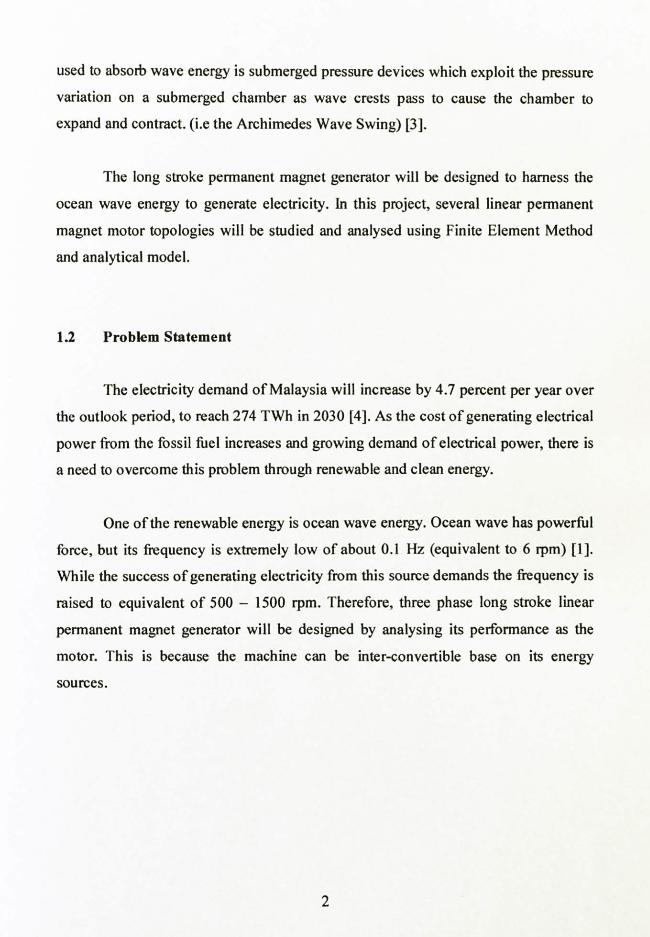
Figure 4 shows rectangular iron core linear permanent magnet motor. The
slotted iron core significantly decreases the working magnetic air gap, thus yields high thrust force. The cogging force also exists because of the strong attractive force
6
between the permanent magnet and the iron core. However, it can be reduced by
skewing the magnet.
Steel forcer
Figure 4 Rectangular iron core linear permanent magnet motor [10]
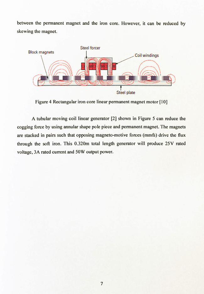
A tubular moving coil linear generator [2] shown in Figure 5 can reduce the
cogging force by using annular shape pole piece and permanent magnet. The magnets
are stacked in pairs such that opposing magneto-motive forces (mmfs) drive the flux
through the soft iron. This 0.320m total length generator will produce 25V rated
voltage, 3A rated current and 50W output power.
7
N-35 MAGNETS. DOUBLE STACKED N
ýýý`
SOFT IRON POLE TIPS
ýý _'_. ý
N
S
S
3
04, ý.
N
N
Figure 5 Moving-coil linear generator [2]
2.2.2 Moving-iron motor
Moving-iron permanent magnet linear motors have simpler designs because
they are usually required to have a uni-directional force capability and use a
mechanical spring to reverse the motion of the plunger when the motor is de-
energised [9].
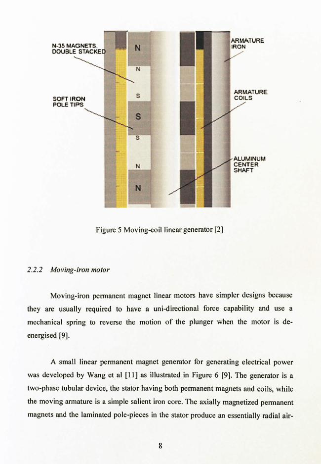
A small linear permanent magnet generator for generating electrical power
was developed by Wang et al [11] as illustrated in Figure 6 [9]. The generator is a two-phase tubular device, the stator having both permanent magnets and coils, while the moving armature is a simple salient iron core. The axially magnetized permanent magnets and the laminated pole-pieces in the stator produce an essentially radial air-
8
gap field. The stator winding flux linkage is modulated by the linear movement of the
armature, and generates an induced electromotive force (EMF). This 48mm axial
stroke linear generator produces 3mJ energy and its average speed is 0.3m/s.
Permanent magnet Lamination
Non-magnetic spacer
Figure 6 Moving-iron linear generator for low power application [9]
Throughout comparison of the previous topologies of moving-iron motor, the
conclusion is the moving-coil motor suffers some disadvantages such as:
i. Heavy weight of moving mass ii. Relatively low thrust force
Therefore, moving-iron topologies will not be considered for designing the long
stroke linear permanent magnet generator.
2.2.3 Moving-magnet motor
There are many topologies for moving-magnet motor. The moving-magnet
motor can have different permanent magnet magnetisation direction which are radially or axially magnetised as shown in Figure 7 and Figure 8. Axially magnetised topology has higher specific force capability than the radially magnetised topology. It
9

also offers lower manufacturing cost, because its permanent magnets are simply
magnetised.
Coll wmtling
Disk magnet
Steel housing
_. ý
Figure 7 Axially magnetised cylindrical moving magnet linear motor[ 10]
Coil winding
Steel core --
Steel housing
Lý1 IL iL i'ý LiL
ý Ring magnets -
ý -- \
Figure 8 Radially magnetised cylindrical moving magnet linear motor [10]
As for the linear motor in Figure 7, the magnetic flux is squeezed through the
pole piece between the oppositely polarized magnets. Thus, it increases the magnetic field (0.6 - 1.2 times the magnet material's B, value) [10]. Figure 9 shows the
magnetic field is channelled from the permanent magnet into the coil by the pole
i V'
I 4-
10
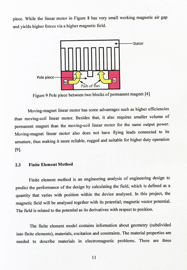
piece. While the linear motor in Figure 8 has very small working magnetic air gap
and yields higher forces via a higher magnetic field.
Stator
Figure 9 Pole piece between two blocks of permanent magnet [4]
Moving-magnet linear motor has some advantages such as higher efficiencies
than moving-coil linear motor. Besides that, it also requires smaller volume of
permanent magnet than the moving-coil linear motor for the same output power. Moving-magnet linear motor also does not have flying leads connected to its
armature, thus making it more reliable, rugged and suitable for higher duty operation
[9].
2.3 Finite Element Method
Finite element method is an engineering analysis of engineering design to
predict the performance of the design by calculating the field, which is defined as a
quantity that varies with position within the device analysed. In this project, the
magnetic field will be analysed together with its potential; magnetic vector potential. The field is related to the potential as its derivatives with respect to position.
The finite element model contains information about geometry (subdivided
into finite elements), materials, excitation and constraints. The material properties are needed to describe materials in electromagnetic problems. There are three
11

electromagnetic material properties which are permeability, permittivity (or dielectric
constant) and electrical conductivity. These material properties may vary with
temperature or frequency or other physical parameters.
In this project, two-dimensional (2D) axisymmetric finite element model of
motor will be developed using open source software. 2D finite element means by
definition, it connects three or more grid points forming a 2D plane, and all potentials
and fields in the element can vary in the two directions of the plane. Figure II and 12
show how three-dimensional (3D) cylinder in Figure 10 is modelled as axisymmetric
problem and planar problem respectively.
Z
xy
Figure 10 3D cylindrical tube
Z
r
Figure 11 Axisymmetric problem Figure 12 Planar problem
12
2.3.1 Boundary Condition
There are five boundary conditions exist for the magnetic and electrostatic problem, which are [121:
a. Dirichlet. In this type of boundary condition, the value of potential A or V is
explicitly defined on the boundary, e. g. A=0. By defining A=0 along a boundary in magnetic problem, keeping magnetic flux from crossing the boundary.
b. Neumann. This boundary condition specifies the normal derivative of
potential along the boundary. In magnetic problems, the homogeneous
Neumann boundary condition, en =0 is defined along a boundary to force
flux to pass the boundary at exactly a 90° angle to the boundary. This sort of boundary condition is consistent with an interface with a very highly
permeable metal.
c. Robin. The Robin boundary condition is sort of a mix between Dirichlet and Neumann, prescribing a relationship between the value of A and its normal derivative at the boundary. An example of this boundary condition is:
OA ön+cA=0
This boundary condition is most often in FEMM to define "impedance
boundary conditions" that allow a bounded domain to mimic the behavior of
an unbounded region. d. Periodic. A periodic boundary conditions joins two boundaries together. In
this type of boundary condition, the boundary values on corresponding points of the two boundaries are set equal to one another.
e. Antiperiodic. The antiperiodic boundary condition also joins together two boundaries. However, the boundary values are made to be of equal magnitude but opposite sign.
13

CHAPTER 3
METHODOLOGY
3.1 Procedure Identification
Literature review of linear machine has been conducted. It is done through
collecting information from electrical and electronic journal, thesis, textbooks and
websites. This literature review covers the linear motor theory, types of linear
machine and the various topologies of linear machine. There are many types of linear
machine such as linear induction machine, linear synchronous machine, linear
switched reluctance machine, linear DC machine and linear permanent magnet
machine. However, the scope of the literature review will focus only on the linear
permanent magnet machine. The topologies of linear permanent magnet machine can be grouped into three major groups which are moving-magnet machine, moving-iron
machine and moving-coil machine.
Through the findings from literature review, two new topologies of linear
permanent magnet machine have been proposed. The performance of the proposed
machine topologies is analysed by using finite element analysis. Finite element
analysis is being carried out to analyse the magnetic flux distribution and motor's
efficiency. Then, optimisation of the motor's parameters will be done base on the
result of the finite element analysis. The project procedures are summarised in the
Figure 13.
14

Design and Modeling Long Stroke Linear Permanent Magnet Motor
t Start
Feasibility studies of tidal wave generating
system
4 Literature review of current
linear motor topologies 4
Propose new linear motor topology
t Design and modeling
using FEMM
T Finite element
analysis of proposed topology
i Optimisation of motor
dimension
i End
Figure 13 Project methodology
15
3.2 Methodology
The important activity in this project is the finite element analysis of the
design. The geometry of the design will be drawn using FEMM and all the material
needed will be assigned to the parts of the machine. The magnetic flux distribution of
the machine under no load condition will be analysed at its initial position and at
maximum stroke length. If the magnetic flux distribution is symmetrical at both tooth
of the stator when the armature is at initial position, then, magnetic flux distribution
of the machine will be analysed when the armature is at the maximum stroke length.
After that, the efficiency of the machine will be calculated. Efficiency of the machine is affected by the power losses which are copper loss, iron loss and eddy current loss.
Based on the finite element result, dimension of the motor will be optimised such as
magnet length, width of back iron, height of the slot, radius of the air-cored, and
width of the stator slot opening.
The future works of this project involves analytical analysis of the machine's
design using the Matlab Simulink. Both results of finite element analysis and
analytical analysis will be validated.
3.3 Tools and Equipment Required
3.3.1 Finite Element Method Magnetic
Finite Element Method Magnetic version 4.2 (FEMM v4.2) will be used to do
finite element analysis of the linear permanent magnet machine design. An analysis in
FEMM involves three distinct steps, which are:
a. Preprocessing: The user provides data such as the geometry, materials and
element type to the program. b. Solution: The user defines the type of analysis, set boundary conditions,
apply loads, and initiate finite element solutions.
16

c. Post processing: The user reviews the results of the analysis through
graphical displays and tabular listing.
Design optimisation of the proposed new topology of linear permanent
magnet machine will be done base on the result of the finite element analysis.
17

CHAPTER 4
RESULTS AND DISCUSSION
4.1 The Proposed Designs
The most important criterion that will be analysed for the long stroke linear
permanent magnet machine are the stroke's length, the magnetic field and its flux
distribution, the thrust force, motor's efficiency and cost-effectiveness. Base on these
criterions, moving magnet topology has been chosen for the design of long stroke linear permanent magnet machine. Two designs have been proposed for further
analysis, which are three phase air-cored quasi-hallbach magnetised machine with
rectangular magnet and three phase air-cored quasi-hallbach magnetised machine
with trapezoidal magnet. Both machine are tubular motors with slotted stator made of
mild steel. Figure 14 and 15 show the air-cored quasi-Halbach magnetised machine
with rectangular magnet and air-cored quasi-Halbach magnetised machine with
trapezoidal magnet, respectively.
Iron
Coil f--Air
Figure 14 Air-cored quasi-hallbach magnetised machine with rectangular magnets
18

Iron
Coil
-. T 4-- 1 i/-+\i/'- i-AiC
Figure 15 Air-cored quasi-halbach magnetised machine with trapezoidal magnets
The design parameters and specification of tubular long stroke linear
permanent magnet machine are shown in Table 1. Details of the design parameters for both machines are included in the Appendix III and Appendix IV.
Table 1: Design parameters and specification of the machines Item Value Units Outer diameter of stator 300 mm Axial length of machine 400 mm Length of pole-pitch 10 mm Height of the air-gap 1 mm Height of the magnet 10 mm Permanent magnet material Sintered NdFeB Remanence of permanent magnet
1.045 T
Coercivity of permanent magnet
891300 A/m
19
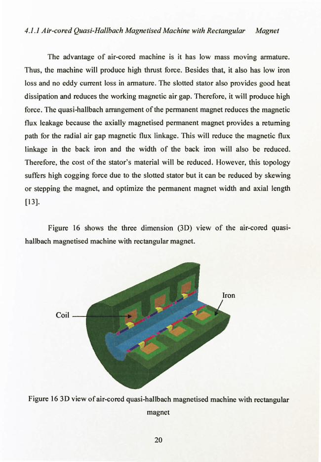
4. ]JA ir-cored Quasi-Hallbach Magnetised Machine with Rectangular Magnet
The advantage of air-cored machine is it has low mass moving armature.
Thus, the machine will produce high thrust force. Besides that, it also has low iron
loss and no eddy current loss in armature. The slotted stator also provides good heat
dissipation and reduces the working magnetic air gap. Therefore, it will produce high
force. The quasi-hallbach arrangement of the permanent magnet reduces the magnetic
flux leakage because the axially magnetised permanent magnet provides a returning
path for the radial air gap magnetic flux linkage. This will reduce the magnetic flux
linkage in the back iron and the width of the back iron will also be reduced.
Therefore, the cost of the stator's material will be reduced. However, this topology
suffers high cogging force due to the slotted stator but it can be reduced by skewing
or stepping the magnet, and optimize the permanent magnet width and axial length
[13].
Figure 16 shows the three dimension (3D) view of the air-cored quasi- hallbach magnetised machine with rectangular magnet.
Coil
Figure 16 3D view of air-cored quasi-hallbach magnetised machine with rectangular
magnet
20
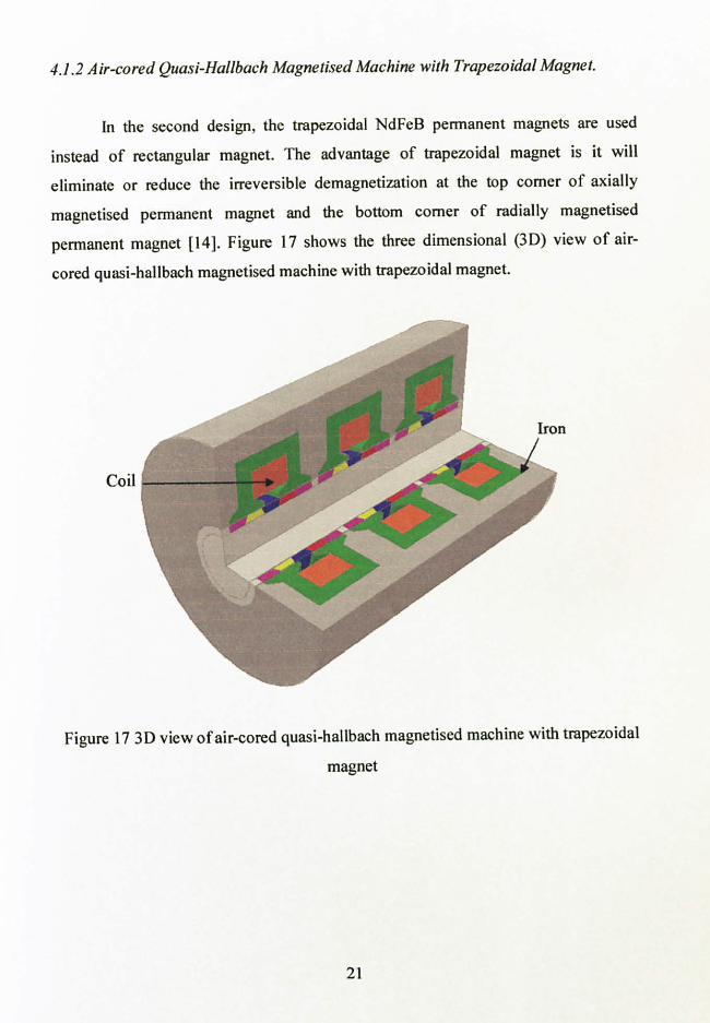
4.1.2 Air-cored Quasi-Hallbach Magnetised Machine with Trapezoidal Magnet.
In the second design, the trapezoidal NdFeB permanent magnets are used
instead of rectangular magnet. The advantage of trapezoidal magnet is it will
eliminate or reduce the irreversible demagnetization at the top corner of axially
magnetised permanent magnet and the bottom corner of radially magnetised
permanent magnet [141. Figure 17 shows the three dimensional (3D) view of air-
cored quasi-hallbach magnetised machine with trapezoidal magnet.
Coil
Figure 17 3D view of air-cored quasi-hallbach magnetised machine with trapezoidal
magnet
21

42 Finite Element Analysis of Air-cored Quasi-Halbach Magnetised
Machine with Rectangular Magnet
Figure 18 and 19 show the magnetic flux distribution for the air-cored quasi- hallbach magnetised machine with rectangular magnets when the moving magnet is at initial position, z=Omm and at maximum stroke position, z=l8mm, respectively. In
both cases, the frequency is set to zero and no load is applied to the motor. From the figure below, the magnetic flux is almost symmetry at both tooth of the iron core. This shows that the configuration of the permanent magnet is correct. There is no
magnetic flux passing through the back iron of the stator because the magnetisation
vector of permanent magnet set A is cancelling the magnetisation vector of
permanent magnet set B.
0
A B
Figure 18 Magnetic flux distributions at initial position, z=0mm
:0
"
22

Figure 19 Magnetic flux distribution at maximum stroke position, z=l8mm
Figure 20 shows the magnitude of air-gap magnetic flux density. There is a drop of magnitude of air-gap flux density at several points along the axial length of the machine. This is due to the slot effect of the machine. Besides that, the selection
of good size of mesh will determine the accuracy of the result of finite element
analysis of the generator especially the size of the mesh of the air gap between the
stator and the moving permanent magnet. In this analysis, air gap region is divided
into four regions with mesh's size of 0.2mm of each region.
Magnitude of B, T 1.40E+00
1.20E+00
1.00E+00
8.00E-01
6.00E-01
4.00E-01
2.00E-01
0.00E+00
A jv7vý1
yýJýýý 8 . -'I NM
tD N 00 O . -r Mý
. O-1 1-4 rpl
pN NNNNNN
+ýýýTý? Q%
NO0 M Ný! ' ýO
ý Q1 m al
O l0 co Ch '-l -l ! 'l rl . -i w1 N
'- l7L NNNNNNNNN
5? 5? ýýý9 5? ?9 WWWWW0W C-4 00
WWW eWý
WW 0
N It 111 n
Q1 ONM tJ1 00 NNNNNMMMMM M)
Armature length, mm
Figure 20 Magnitude of air-gap magnetic flux density
23

The design parameter of the machine has been optimised in terms of the ratio
of radially magnetised magnet's length, Tm, over pole's length, T. The optimum Tmr 1'p
ratio is determined by analysing the efficiency of the machine. The analysis of the
machine output power is done as per phase. That means the first phase of the machine
only is analysed using finite element method (single phase of the motor is shown in
Figure 21). This is because in three phase system, the total output power of the
machine is three times the power of single phase machine. 2.5A current is supplied to
the machine at the frequency of 50Hz while the number of turns of the coil is set to
1680 turns. The result of the simulation is shown in Table 2 and Figure 22.
I { -- f -- + 0 0 0
I 435,0000
Figure 21 Single phase air-cored quasi-hallbach magnetised machine with rectangular
magnet
Table 2 Comparison of machine's efficiency with varying TmrITp
TmýTP Tmr (mm) TP (mm) Pin (W) Piou (W) Pouc (W) Efiiciency, rl (%)
0.4 18 45 1358.93 295.72 1063.20 78.24 0.45 20.25 45 1363.75 296.10 1067.65 7829 0.5 22.5 45 1354.68 259.02 1095.66 80.88 0.55 24.75 45 1358.22 295.59 1062.63 78.24 0.6 27 45 1365.19 296.35 1068.84 78.29
24

ý V G !! U
ý W
81.50
81.00
80.50
80.00
79.50
79.00
78.50
78.00
77.50
77.00
76.50
0.4 0.4S 0.5 0.55 0.6
Tmr/Tp
Figure 22 The graph of machine's efficiency versus T,,, T/Tp.
25

4.3 Finite Element Analysis of Air-cored Quasi-Halbach Magnetised
Machine with Trapezoidal Magnet
Figure 23 and 24 show the magnetic flux distribution for the air-cored quasi- hallbach magnetised machine with trapezoidal magnets when the armature is at initial
position (z=0mm) and at the maximum stroke position (z=14mm). In both cases, the frequency is set to zero and no load is applied to the motor.. From the figure below,
the magnetic flux is almost symmetry at both tooth of the iron core. This shows that
the configuration of the permanent magnet is correct.
Figure 23 Magnetic flux distributions at initial position, zOmm
Figure 24 Magnetic flux distributions at maximum stroke position, z=14mm
26

Figure 25 shows the graph of magnitude of air-gap magnetic flux density
versus the length of the machine. The maximum magnitude of magnetic flux density is about 1.27T. It is higher than the maximum magnitude of magnetic flux density of air-cored quasi-Halbach magnetised generator with rectangular magnet which is
1.20T. Therefore, trapezoidal quasi-hallbach magnet increases the magnetic flux
density at the air gap.
Magnitudeaf B, T 1.40E+00
1.20E+00
1.00E+00
8.00E-01
6.00E-01
4.00E-01
2.00E-01
0.00E+00
ý-l 14 +ý °+ u., ww 8IRN d 1-4
ööö öý ööööäöööÖöööööööö ++++++++++++++++++++ WW WýWýpp WWW
Ln -I W
nW W
QWQ1ý WW
pWp W
pWp tWp WWWWW
Mý OýO
M Ný lD
FOM1O Ný Mh 01 ON
co nO^ý
.... . -. I
............. e} %p pp 01 -i M . -ý rl . -1 ri NNNNNNMMMMMM
Armature length, mm
Figure 25 Magnitude of magnetic flux density at the air gap
27

CHAPTER 5
CONCLUSION AND RECOMMENDATION
5.1 Conclusion
Literature review on various linear machine topologies has been done and the
topologies can be grouped into three groups which are moving-coil, moving-iron and
moving-magnet machine. Based on that information, moving-magnet topology has
been selected for designing two designs of long stroke linear permanent magnet
machine which are air-cored quasi-hallbach magnetised machine with rectangular
magnet and air-cored quasi-hallbach magnetised machine with trapezoidal magnet.
Finite element analysis has been conducted on both machines and optimisation of the
t, n, Jtp has been done to air-cored quasi-hallbach magnetised machine with rectangular
magnet. Therefore, air-cored quasi-hallbach magnetised machine with rectangular
magnet can be further developed for generating electricity from the ocean wave.
5.2 Recommendation
Base on the findings, further optimisation of the design will be focused on
these parameters which are: i. radius of the air-cored
ii. height of the permanent magnet
Besides that, further analysis will be carried out using analytical model to
validate the finite element analysis result.
28

REFERENCES
[1] L. Freris and D. Infield, Renewable Energy in Power Systems, United
Kingdom, John Wiley & Sons Ltd, 2008.
[2] K. Rhinefrank, E. B Agamloh, A. von Jouanne, A. K. Wallace, J. Prudell, K.
Kimble, J. Aills, E. Schmidt, P. Chan, B. Sweeny, and A. Schacher, "Novel
ocean energy permanent magnet linear generator buoy, " Renewable Energy
31, pp. 1279 - 1298, September 2005.
[3] B. D. Hazlett, I. I. Inculet and D. R. Inculet, "Electric power generation by
`Surfing' water waves, " Renewable Energy 34, pp. 2510-2514, March 2009.
[4] Asia Pacific Energy Research Center,
<http//www. ieej. or. jp/aperc/2006pdf/Outlook2006/Whole Report. pdf, 2006.
1s1 "linear motor" A Dictionary of Physics. Ed. John Daintith. Oxford University
Press, 2009. Oxford Reference Online. Oxford University Press.
[6] V. N. Hoang, "Design of a single-sided linear induction motor", Degree
Thesis, The University of Queensland, Australia, 2003.
[7] 1. Boldea and Syed A. Nasar, Linear Electric Actuators and Generators,
Australia, Cambridge University Press, 1997.
29
[8] R. C. Okonkwo, 2006, "Design and performance of permanent-magnet dc
linear motors", IEEE Transactions on Magnetics, vol. 42, No. 9, pp. 2179 - 2183, September 2006.
[9] T. Ibrahim, "Short-stroke, single phase tubular permanent magnet motor for
refrigeration applications", PhD Thesis, University of Sheffield, 2009.
[10] A. C. Morcos, "The straight attraction, part two", Motion Control, pp. 24 - 28, July/ August 2000.
[11] J. Wang, W. Wang, G. W. Jewell, and D. Howe, "A low-power, linear,
permanent-magnet generator/energy storage system", IEEE Transactions on Industrial Electronics, vol. 49, No. 3, pp. 640 - 648, June 2002.
[12] D. Meeker, Finite Element Method Magnetics version 4.2 User's Manual,
2009.
[131 N. Bianchi, S. Bolognani, D. D. Corte, and F. Tonet, "Tubular linear
permanent magnet motor: an overall comparison", IEEE Transactions on Industry Application, vol. 39, No. 2, pp. 466 - 475, March/ April 2003.
[14] J. Wang, W. Wang, K. Atallah, and D. Howe, "Demagnetization Assessment
for Three-Phase Tubular Brushless Permanent-Magnet Machines", IEEE
Transactions on Magnetics, vol. 44, no. 9, pp. 2195 - 2203, September 2008.
30

APPENDICES
31

APPENDIX I" Planned Milestone for the First Semester of Final Year Project
No. De 111 Week 1 2 3 4 5 6 7 8 9 10 11 12 13 14 15 1 Selection of Project Topic
2 Preliminary Research Work Feasibility study of tidal wave generating system (tidal power, cost, energy policies and environmental effects)
3 Submission of Preliminary Report
4 Seminar 1
5 Project Work i. Literature review of current linear machine
topologies
6 Submission of Progress Report
7 Seminar 2
8 Project work continues i. Identify factors that reduce machine
efficiency ii. Proposed new topology
iii. Analysis of magnetic flux distribution
9 Submission of Interim Report Final Draft
10 Submission of Interim Report
11 Oral Presentation
p Process Suggested Milestone
32
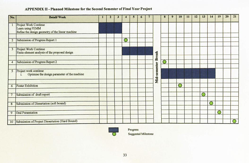
APPENDIX II - Planned Milestone for the Second Semester of Final Year Project
No. Detxi /Week 1 2 3 4 5 6 7 8 9 10 11 12 13 14 19 20 21
1 Project Work Continue Learn using FEMM Refine the desi geometry of the linear machine
2 Submission of Progress Report 1 1 01
3 Project Work Continue Finite element analysis of the proposed design
w
4 Submission of Progress Report 2
5 Project work continue i. Optimise the design parameter of the machine
E
ti
6 Poster Exhibition O
7 Submission of draft report
8 Submission of Dissertation (soft bound) O 9 Oral Presentation
10 Submission of Project Dissertation (I-lard Bound)
Progress Suggested Milestone
33

APPENDIX III - Dimension Of Air-Cored Quasi-Halbach Magnetised Generator With Rectangular Magnets
+ lomm
4
400mm go .
90mm ý
10mm E E
ý 0 ý 20 3
1
50mm i-º } ý-t i -ý * ý-t iý fti
Mýº ýI If ý- T., T., 1T. T. J2
- 90mm ý
-º Tý i
Timm
f39mm
34

APPENDIX IV - Dimension Of Air-Cored Quasi-Halbach Magnetised Generator
With Trapezoidal Magnets
400mm
f q- - 90mm
s --o
20mm 0 E
ý: zz z_ -: sxý -1 ý 1o
-e-y 1 -4 ýe_ Q4
-T-i, -6 j+-a- ;
E ý 0 ý
39mm
35