Embed Size (px)
Citation preview
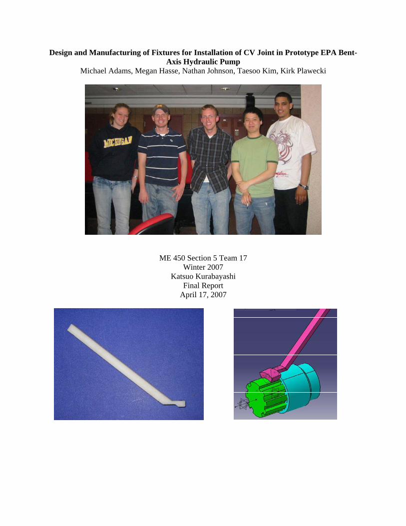
Design and Manufacturing of Fixtures for Installation of CV Joint in Prototype EPA Bent-Axis Hydraulic Pump
Michael Adams, Megan Hasse, Nathan Johnson, Taesoo Kim, Kirk Plawecki
ME 450 Section 5 Team 17 Winter 2007
Katsuo Kurabayashi Final Report
April 17, 2007

1
ABSTRACT The United States Environmental Protection Agency (EPA) has developed a hydraulic hybrid system for delivery trucks. The barrel-valveplate is a component that is frequently changed due to constant tests to the proprietary bent-axis Gen 2 pumps of the hydraulic system. Installation of the barrel-valveplate includes aligning piston-con-rod assemblies into barrel bores, aligning and mating CV joint assemblies, and the installation of a backplate assembly. The CV joint installation is very difficult due to the piston-con-rod assemblies surrounding it. Thus, Dr. Mike Delduca, from EPA contacted us to design a removable tool that will facilitate CV joint alignment and reduce the alignment time to less than two minutes. TABLE OF CONTENTS Introduction………………………………………………………………………………… 2 Information Search…………………………………………………………………………. 2 Customer Requirements and Engineering Specifications………………………………….. 4 Customer Requirements……………………………………………………………. 4 Engineering Specifications………………………………………………….……... 5 QFD Chart………………………………………………………………………….. 6 Benchmarking……………………………………………………………………… 6 Concept Generation………………………………………………………………………... 7 Magnetic Tools…………………………………………………………………….. 7 Moldable Concepts………………………………………………………………… 8 Automatic Alignment………………………………………………………………. 9 Manual Manipulation with Wedge Tool…………………………………………… 9 Concept Evaluation and Selection…………………………………………………………. 10 Concept Elimination……………………………………………………………….. 10 Top Five Concepts…………………………………………………………………. 10 Selected Concepts/Final Designs………….……………………………………………….. 11 Engineering Analysis………………………………………………………………………. 17 Coupler Static Analysis…………………………………………………………….. 17 Adjustable Magnetic Tool Static Analysis……………………………….………... 17 Stepped Magnetic Alignment Tool Static Analysis………………………………... 18 Wand Static Analysis………………………………………………………………. 19 Bird of Prey Static Analysis………………………………………………………... 20 Final Design Static Analysis……………………………………………………….. 21 Final Design Friction Analysis…………………………………………………….. 22 Material Choice…………………………………………………………………….. 23 Magnet Specifications……………………………………………………………… 23 Finite Element Analysis (FEA) on Selected Concepts…………………………….. 24 Adjustable Magnetic Tool………………………………………………….. 24 Bird of Prey………………………………………………………………… 25 Wand……………………………………………………………………….. 26 Final Design………………………………………………………………... 27 Manufacturing Plans……………………………………………………………………….. 29 Fused Deposition Modeling (FDM)……………………………………………….. 29

2
Prototype Assembly………………………………………………………………... 30 Testing/Validation – Choosing the Final Design…………………………………………... 30 Adjustable Magnetic Tool………………………………………………………….. 30 Bird of Prey………………………………………………………………………… 31 Moldable Putty……………………………………………………………………... 32 Wand……………………………………………………………………………….. 33 Stepped Magnetic Alignment Tool………………………………………………… 34 Testing Results……………………………………………………………………... 34 Final Design………………………………………………………………………………... 36 Assembly of the CV Joint Using the Final Design………………………………… 36 Future Improvements………………………………………………………………. 38 Project Plan………………………………………………………………………………… 38 Conclusions………………………………………………………………………………… 38 Acknowledgements ………………………………………………………………………... 38 References………………………………………………………………………………….. 39 Team Biographies………………………………………………………………………….. 39 Appendix…………………………………………………………………………………… 41
INTRODUCTION The EPA Advanced Technology Division (ATD) is currently working to increase the efficiency of their hydraulic hybrid systems. This system is designed to improve the fuel efficiency of vehicles ranging from passenger vehicles to large trucks. As a result of the EPA’s continuing design changes, they must reassemble sections of the system frequently with modified components. Due to the complexity of many of the components in the system, this proves to be a time consuming and difficult task. One of the parts the EPA is looking to improve is the hydraulic pump used in prototype hybrid vehicles. When a design change is made to the pump, it usually requires disconnecting the constant velocity (CV) joint located within the pump, and removing the backplate assembly. When the pump is reassembled, the nine pistons that encircle the CV joint must be aligned first. This results in very limited space to align the CV joint manually. However, this is the only method available to assemble this part, and it is a time consuming and difficult task. Thus, the EPA has asked us to develop a tool or fixture to assist them in aligning the CV joint. Once the CV joint is aligned, the tool must be removed from the part before the backplate can be attached. It was also requested that this tool be applicable to a variety of CV joints and that the alignment take less than two minutes to complete. INFORMATION SEARCH The bent-axis Gen 2 hydraulic pump is patented by the EPA, so finding similar products for benchmarking purposes is not possible for this project. We found a Microsoft PowerPoint presentation that was given to the public by the EPA about the hydraulic hybrid program and an overview on how the hydraulic hybrid system works [1]. This document provided useful background information on the system as a whole. Fig. 1 on page 3 is a diagram of the pump from this document.

3
Fig. 1: Diagram showing important parts of the Gen 2 Hydraulic pump [1]
The location of the CV joint that requires an alignment tool is attached to the backplate assembly which is shown in Fig. 1 above. A more detailed diagram showing some of the specific parts our team will have to work around is shown in Fig. 2 below, which was created in CATIA. Our tool will have to fit in between the connecting rods in order to reach the CV joint. Fig. 2: Diagram of backplate assembly showing location of CV joint and pistons [1]

4
We also found information about the piston-con-rod alignment tool that was designed and manufactured by ME 450 students at the University of Michigan during the winter of 2006 semester. The fixture they designed was three separate pieces that slipped together to create the piston alignment fixture [2]. This fixture is featured below in Fig. 3. Fig 3. The piston-con-rod alignment tool designed by a previous ME 450 group [2]
CUSTOMER REQUIREMENTS AND ENGINEERING SPECIFICATIONS We organized all of the customer’s requirements, engineering specifications, and benchmarking by utilizing a Quality Function Development (QFD). After determining all of the aforementioned specifications, we filled out the QFD diagram as shown in Fig. 4 on pg. 6. Customer Requirements We determined the weight of the customer requirements by discussing with Dr. Andrew Moskalik, an associate of our sponsor at the EPA, about where the hydraulic hybrid team could benefit the most with the help of a tool. After getting a view of the component and the location of where our tool is going to be used, we determined some of the requirements considering the many constraints of the environment. The over-riding requirement of the design is that our final product should reduce assembly time of the component down to around two minutes. Also, it needs to require only one hand to operate, as the assembler must have a free hand to push the assembly together once the joint is aligned. Other necessary requirements of the tool are that it must be removable from the component, and it also needs to fit in a considerably tight space during assembly. Ideally, our design should be easy to use. Tool assembly time should be minimal and included in overall assembly time. Since the EPA has been continually updating their design, the CV joints used in the pumps vary. Our tool must accommodate the slight differences between the CV joints currently in use and any future design revisions that the EPA may implement.

5
Many of the requirements we determined relied on the material composition of our final product. Because we are aiding in the assembly of a hydraulic component, our tool could be exposed to hydraulic fluid, as well as the lubricants used in the assembly of the component. The tool cannot react with these substances. Also, the tool must not wear easily and leave debris that could cause damage to the CV joint and precision parts that surround it. The tool should be relatively inexpensive overall, and material choice weighs considerably in this aspect, not only in raw material cost, but also in how the tool is made. After determining these main customer requirements, we weighed them depending on importance and put them into the QFD diagram. Engineering Specifications Using the customer requirements, we then determined necessary engineering specifications. First and foremost, we decided that the install time of the backplate assembly must not exceed two minutes, since shortening the assembly time is the main goal of our project. Our tool must also be quite small in order to fit in the constrained workspace. We want to keep the number of parts to a minimum not only to simplify the manufacturing of the tool, but also to make the tool much less complex to use. We also consider the material to be quite important, though mostly for cost purposes. It is important to keep the price of the tool relatively low to stay within budget, but due to the scope of the project and the tool being used strictly for prototype assembly, no consideration must be made for mass production cost. A few less important specifications we explored were the manufacturing method, which depends primarily on the material we choose, disposability of the tool in case we design for a single-use product, tool life, failure load, tool weight, and maximum drop height, for durability purposes. After determining these main engineering specifications as summarized in Table 1 below, we correlated them with each other as well as how they affect the customer requirements. These correlations are reflected in the QFD diagram as well. Table 1: List of engineering specifications
Life of tool Manufacturing methodMax drop height Install time < 2 minFailure load Weight <150gMaterial DimensionsNumber of parts Disposability

6
Fig. 4: Quality function development chart for CV joint alignment tool Relationships++ Strong Positive
+ Medium Positive
- Medium Negative
- - Strong Negative
(+) => more is better (-) => less is better
Weight* Life
of t
ool
Max
dro
p he
ight
Failu
re lo
ad
Mat
eria
l
Num
ber o
f par
ts
Man
ufac
turin
g m
et
Inst
all t
ime
< 2
min
Wei
ght <
150g
Dim
ensi
ons
Dis
posa
bilit
y
Quick install time 10 3 9 1 3Easy to use/ergonomics 8 1 3 9 9 9Must be removable 10 3 1 3 9 3Fit variety of joints 5 1 9Inexpensive 3 3 3 3 9 9 9 1 9Works in available space 10 3 1 3 9 3Doesn't leave debris 7 1 3 9 3 9 3Durable 5 9 9 9 9 3 3 3Safe to use 7 1 3 1 3 1 3 1Resists corrosion/deterioration 8 9 3 9 3 1Easy to manufacture 5 9 9 9 1 3One handed operation 10 9 9 1
Yrs m N # min g m7 10 8 4 3 5 1 9 2 6
140 54 120 267 317 159 375 106 342 1530.07 0.03 0.06 0.13 0.16 0.08 0.18 0.05 0.17 0.08
Key:9 => Strong Relationship3 => Medium Relationship1 => Small Relationship(blank) => Not Related
*Weights are figured on a scale of 1 to 10(ten being most important)
Normalized
Measurement UnitImportance Rating
Total
+
++-
+
+
+++
-+
++-
+
- -+
-
+
+++
--
Benchmarking Since our product is going to be used in a new technology that really has no precedent, there are not any products out there with which we can compare.

7
CONCEPT GENERATION The basic and subsidiary functions of the design were identified by investigating the customer and engineering requirements. Since the product we are designing is an alignment tool, it is designed for that function in particular. Additional functions that need to be considered are how the tool is held in place and how the tool is removed once alignment has been completed. Using these functions, a morphological chart was created and is shown as Table 2 on pg. 7.
Table 2: Morphological Chart
Function
Alignment Magnetic Shim Manual Moldable Material Automatic
Holding Clip-on Hand-held Wedge-in Rests on Rods
Removal Break Away Dissolve Intact
Option
Utilizing the morphological chart, high level design concepts were generated. This was accomplished by combining different options for each function. For example, one concept includes a moldable material that will be wedged-in to support the male end of the CV joint. It will be removed intact once the two ends of the joint are aligned. Using a similar process, tool ideas were generated and categorized by alignment type as magnetic, moldable, automatic, and wedge. Magnetic Tools The majority of our ideas involve using magnetic force. From our observations while attempting to assemble the CV joint and our conversations with the sponsor, the largest contributor to the difficulty of assembly is the high degrees of freedom in each end of the joint. Therefore, the majority of our concepts share the common idea of holding either the male or female end of the joint stationary to eliminate this issue. This would allow manipulation of the opposite end using a second simple tool. An example of one of the magnetic tools is shown in Fig. 5 below. Fig. 5: Magnetic Alignment Tool Concept

8
The idea shown in Fig. 5 on pg. 7 includes an adjustable magnetic tool that would rest on top of the connecting rods. This tool would have a magnetic end attached to the end of a threaded rod. The rod goes through the center of a machined piece of aluminum, designed to be held in place by the connecting rods. The position of the magnetic end is adjustable by the key at the top of the tool. Once this tool is placed on top of the connecting rods, a second tool will raise the female end of the joint to the magnetic end of the tool, holding this end of the CV joint in place. Fine adjustment is allowed using the key. The second tool is then used to manipulate the male end of the CV joint, and once aligned, the operator would use his/her free hand to push on the backplate, sliding the joints together. Additional magnetic tools are shown in Appendix A. Moldable Concepts The idea of the moldable fixture follows the same goal of the magnetic tools. By placing a moldable putty or wax between the drive plate and the male end of the connecting rod, the degrees of freedom for this end of the joint can be eliminated, and manipulation of the female end by other means would ease installation. A sketch of this is shown in Fig. 6 below. Fig. 6: Moldable Fixture Concept
The moldable substance in Fig. 6 above would be shaped by pressing the substance into a cavity machined out of plastic or aluminum. Once formed, the putty would be inserted in the space between the drive plate and the male end of the CV joint, holding it steady. Due to clearance issues, this would be done before the pistons are inserted into their barrels on the backplate assembly. Alignment of the female end could be done either manually or with a second tool. Removal of this mold after assembly is dependent on the material chosen. One option is a material that would dissolve quickly once it came in contact with the hydraulic fluid in which the area becomes submerged. The second option is reusable putty that would be easily accessed by displacing the yoke to its maximum at 49 degrees and reaching in from underneath with needle nose pliers or a similar tool.
9
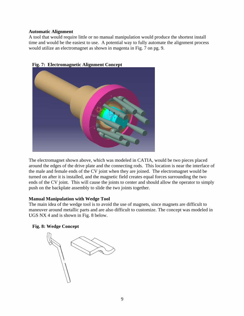
Automatic Alignment A tool that would require little or no manual manipulation would produce the shortest install time and would be the easiest to use. A potential way to fully automate the alignment process would utilize an electromagnet as shown in magenta in Fig. 7 on pg. 9.
Fig. 7: Electromagnetic Alignment Concept
The electromagnet shown above, which was modeled in CATIA, would be two pieces placed around the edges of the drive plate and the connecting rods. This location is near the interface of the male and female ends of the CV joint when they are joined. The electromagnet would be turned on after it is installed, and the magnetic field creates equal forces surrounding the two ends of the CV joint. This will cause the joints to center and should allow the operator to simply push on the backplate assembly to slide the two joints together. Manual Manipulation with Wedge Tool The main idea of the wedge tool is to avoid the use of magnets, since magnets are difficult to maneuver around metallic parts and are also difficult to customize. The concept was modeled in UGS NX 4 and is shown in Fig. 8 below. Fig. 8: Wedge Concept

10
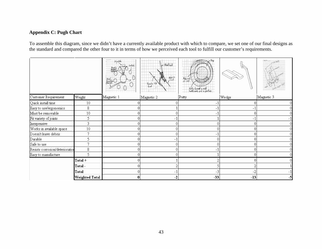
The tool on the left in Fig. 8 on page 9 is designed to wedge in beneath the male end of the CV joint, and will be manipulated to line up the two CV joint components. The tool on the right is designed to wedge in behind the female end, and be hands free once inserted. This leaves one hand to manipulate the male-end tool, and the other to push in the backplate assembly once the two CV joint components are aligned. CONCEPT EVALUATION AND SELECTION The top five concepts for our alignment tool/fixture were decided upon and refined after an additional visit to our sponsor. This gave us new direction allowing us to eliminate the ideas that would not work, and refine the ideas with potential. Concept Elimination A few of our high level design concepts had to be eliminated in order to come up with the top five concepts for comparison in a Pugh chart. The first concept that was eliminated was the moldable putty substance that would dissolve in the hydraulic fluid once immersed so that it would not require removal. Our team decided that this concept is unlikely to work for two reasons: First, the area that this would be installed in would already be covered in hydraulic fluid, so the putty would begin dissolving instantly upon installation unless the area was cleaned beforehand, adding to the install time. Also, if the putty did not dissolve right away, it would interfere with the mechanical parts of the pump. The automatic alignment via electromagnet was also eliminated in the process of choosing our top five concepts. There are two hurdles that would have to be overcome before this idea would work. The first involves the effect the force of gravity would have on the two ends of the CV joint. Gravity would cause the total forces applied to be uneven and as a result the ends of the CV joint would not be perfectly centered. The second is that the two ends of the CV joint would need to be perfectly centered when the electromagnet is turned on in order for the forces to be equal surrounding the joints. The last concept that was eliminated is shown in Appendix A.2. The shortcoming of this tool included a difficult install for the piece that attaches the connecting rod to the end of the CV joint, as well as difficult removal once the two ends of the joint were aligned. This would increase the time it would take to align and assemble the CV joint. Top Five Concepts We narrowed our numerous designs down to five concept options. Three of them employ magnets as a means to align the two pieces of the CV joint, and the other two are intended to prop up one piece of the joint while the other end is manually manipulated into alignment. These were put into a Pugh chart to compare the designs against each other and how well they meet the customer’s requirements. This chart is shown in Appendix C. We intend to combine the best features of each concept to produce the best possible design.

11
SELECTED CONCEPTS/FINAL DESIGNS We chose to carry on all of our top five concepts because of the trial-and-error nature of our project. There best way for us to evaluate the performance of each design is to test them in a real-world situation. Also, it will be quite easy to create a prototype of each design. These five concepts are described below. Concepts 1-3 and 5 were modeled in CATIA, and Concept 4 was modeled in UGS NX 4. Concept 1: Magnetic alignment with adjustability
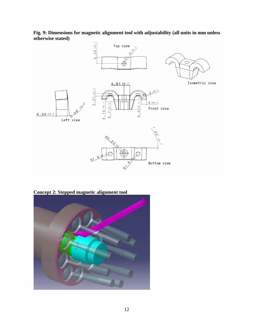
The idea of this design is to hold up the female end of the CV with an adjustable-height magnet that hangs from the top connecting rods. This will hold the female end steady while the male end is manually lined up. The magnet is adjustable by means of a screw, which has been purchased. The rapid prototype of this fixture is made of ABS plastic. The dimensions for this are shown in Fig. 9 on page 12.
12
Fig. 9: Dimensions for magnetic alignment tool with adjustability (all units in mm unless otherwise stated)
Concept 2: Stepped magnetic alignment tool

13
This stepped magnetic alignment tool shown on pg. 12 is intended to line up the two CV joint components with one tool. The step in this design must be precise to compensate for the difference in the outside diameters of the two CV joint couplers to make sure that they are aligned correctly. The wand is there to aid in removal of the tool, as it will be quite difficult to remove after the two CV joint components have been mated together within the assembly. The tool will be made out of ABS plastic. The dimensions for this tool are in Fig. 10 below. Fig. 10: Dimensions for Stepped Tool (all units in mm unless otherwise specified)

14
Concept 3: Molded putty
This design aligns the male end exclusively Due to its limited ability to be manually manipulated. The mold, which will be made of ABS plastic, will be two pieces in order to easily remove the putty without significantly damaging the shape. The molding of the substance should only take a matter of seconds. The moldable material will be reusable, so it must be resistant to the hydraulic fluid and lubricants with which it will come in contact in this usage. The use of putty will allow for minor adjustments while in the assembly, as it can still be manipulated with a prod or finger for fine tuning. It will also be relatively inexpensive, as there are many commercially available products that should be able to perform adequately in this capacity. The dimensions for the mold are in Fig. 11 below. Fig. 11: Mold Dimensions (all units in mm unless otherwise specified)

15
Concept 4: Wand
The Wand is designed to manipulate the male end into alignment in order for the backplate to be moved forward to complete the assembly procedure. The Wand will be made of ABS plastic. The dimensions for the tool are in Fig. 12 below. The dimensions were carefully chosen to fit the opening beneath the male coupler of the CV joint. Fig. 12: Wand Design Dimensions (all units in mm unless otherwise specified)
16
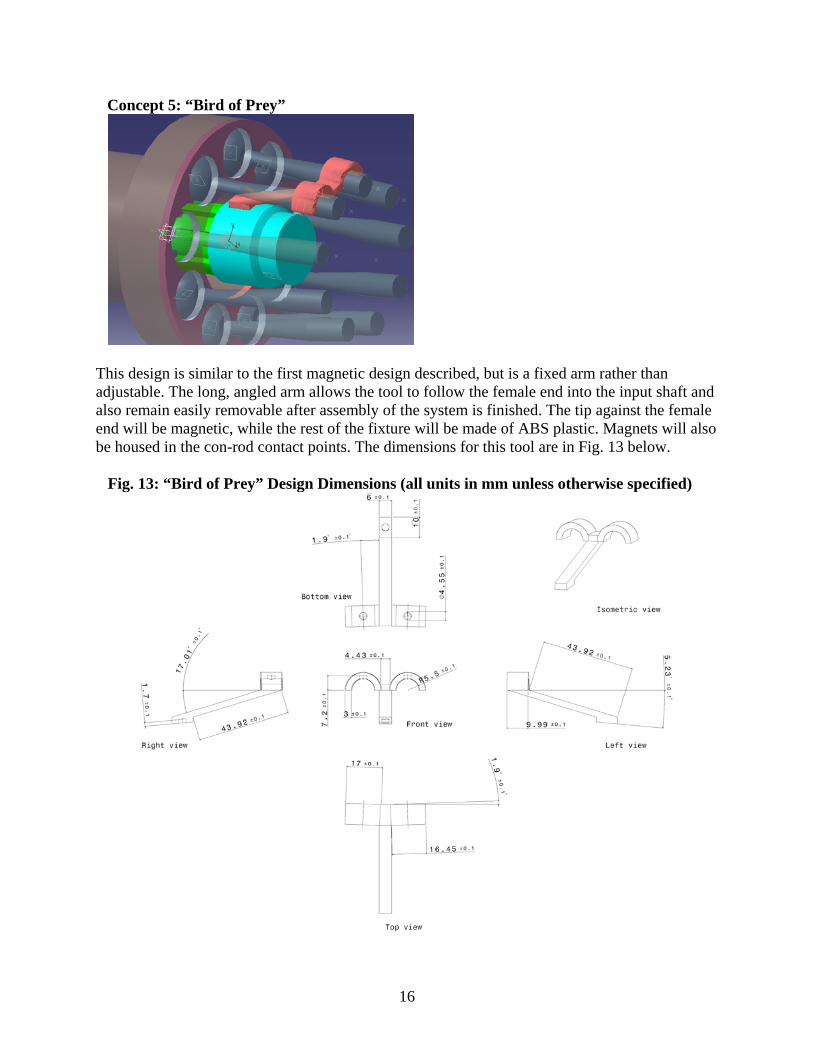
Concept 5: “Bird of Prey”
This design is similar to the first magnetic design described, but is a fixed arm rather than adjustable. The long, angled arm allows the tool to follow the female end into the input shaft and also remain easily removable after assembly of the system is finished. The tip against the female end will be magnetic, while the rest of the fixture will be made of ABS plastic. Magnets will also be housed in the con-rod contact points. The dimensions for this tool are in Fig. 13 below. Fig. 13: “Bird of Prey” Design Dimensions (all units in mm unless otherwise specified)

17
ENGINEERING ANALYSIS Before we could order our parts, we had to complete some basic engineering calculations to determine the load conditions to which our tools would be subjected. We did static analysis and finite element analysis (FEA) for the parts we intended to rapid prototype. Coupler Static Analysis First we completed analysis of the coupler system in order to determine the loads to which each tool would be subjected. Since each tool contacts the coupler at different points, we first had to balance the moments for when the coupler would be held horizontally to determine F, which represents the minimum force necessary to keep the coupler horizontally aligned and in contact with the tools. This is shown in Fig. 14 below. Fig 14: Coupler Free Body Diagram
0zM F x mg l= − ⋅ + ⋅ =∑ , therefore: lF mgx
= ⋅ (1)
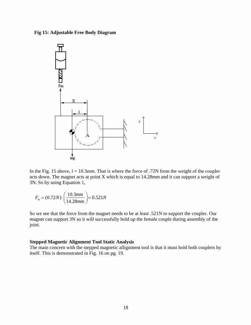
Since the system is working all in the vertical plane, forces in the x and z directions are not taken into account. The variable x depends on where the tool makes contact with the coupler, and m and l depend on which coupler is being aligned. Adjustable Magnetic Tool Static Analysis Our concern with the adjustable tool is if the magnet on the end of the screw will be able to hold up the female coupler so that we may put it into alignment with the male coupler. We created an FBD, shown in Fig. 15, on pg. 18 to analyze the system to determine what force must be overcome by the magnet.
mg
18
Fig 15: Adjustable Free Body Diagram
In the Fig. 15 above, l = 10.3mm. That is where the force of .72N from the weight of the coupler acts down. The magnet acts at point X which is equal to 14.28mm and it can support a weight of 3N. So by using Equation 1,
10.3(0.72 ) 0.52114.28m
mmF N Nmm
⎛ ⎞= ⋅ =⎜ ⎟⎝ ⎠
So we see that the force from the magnet needs to be at least .521N to support the coupler. Our magnet can support 3N so it will successfully hold up the female couple during assembly of the joint. Stepped Magnetic Alignment Tool Static Analysis The main concern with the stepped magnetic allignment tool is that it must hold both couplers by itself. This is demonstrated in Fig. 16 on pg. 19.

19
Fig 16: Stepped Magnetic Alignment Tool Free Body Diagram
The weight of the female coupler is m1g = 0.72N, the distance of the center of gravity to the rotational axis of the female coupler is l1 = 10.3mm, and the distance the tool makes contact with the female coupler to the rotational axis is x1 = 21mm. The weight of the male coupler is m2g = -0.44N, the distance of the center of gravity to the rotational axis of the male coupler is l2 = 7.26mm, and the distance the tool makes contact with the male coupler to the rotational axis is x2 = 10.5mm. Then, by using equation 1, we found the following:
1
10.3(0.72 ) 0.35321
mmF N Nmm
⎛ ⎞= ⋅ =⎜ ⎟⎝ ⎠
27.26(0.44 ) 0.30410.5
mmF N Nmm
⎛ ⎞= ⋅ =⎜ ⎟⎝ ⎠
Since the actual F1 = 3N (Fmagnet = 3N) and the actual F2 = 9N (three magnets), then this tool will keep the couplers sufficiently aligned and secured to the tool. Wand Static Analysis Since the wand is not magnetic and works from beneath the male coupler, we did not have a concern with the coupler becoming detached from the tool. We determined, though, the force which needs to be applied to successfully manipulate the male coupler with the tool, shown in the FBD in Fig. 17 on pg. 20.
m1g m2g

20
Fig 17: Wand In-Use Free Body Diagram
Assume that the Wand acts at the center of gravity of only the male coupler, therefore x = l.
7.26(0.72 ) 0.727.26
mmF N Nmm
⎛ ⎞= ⋅ =⎜ ⎟⎝ ⎠
This means that the minimum force applied to the coupler by the tool must be 0.72N in order to manipulate the coupler for joining purposes. Bird of Prey Static Analysis The issue with the Bird of Prey tool is whether or not it will detach from the connecting rods due to the weight of the female CV joint. The analysis of this situation is shown in Fig. 18 below.
Fig. 18: Bird of Prey Free Body Diagram
mg F

21
To find out if the tool will detach from the connecting rods, we took moments around point X. If the tool is to stay planted then :
1 2 3
6 5 0.002 5 0.002 21.22 0.615 40.0630.01 24.68
x x xM M MN mm N mm N mm N mm
N mm N mm
≥ +⋅ + ⋅ ≥ ⋅ + ⋅
⋅ ≥ ⋅
There are two magnets at M1 which result in a 6N force. That force plus the force from the weight of tool/magnet combo cause M1 to be greater so we know the tool will be able to sufficiently support the female coupler. Final Design Static Analysis
Fig 19: Removal Force Free Body Diagram
All units in N, mm
18N6N
13.5
F
This FBD shows how much force is necessary to remove our final tool design from its place after the couplers have been mated together. Although 37.34 N is substantial (~8.4 lbs), it is quite easy to remove the tool by applying a moment perpendicular to the handle to aid in release of a few magnets.
NFFNNFY
34.370)40sin()6()18(
=
=+−−=∑

22
Fig 20: Moment Analysis Free Body Diagram
All units in N, mm
18N6N
13.5
Fy
Fx
F
A
NFmmFmmFmmNmmNM zA
18.10)38.64)(40sin()12.95)(40cos()5.13)(6()3)(18(,
=
=++−−=∑
From this FBD, we can see that removal of the tool is quite easy if a moment about the tip is applied, requiring only 1.18N. Final Design Friction Analysis Since the male coupler is supposed to slide beneath our final design, we had to make sure that the coupler would not detach from the tool during this sliding action. The FBD in Fig. 21 on pg. 23 shows the friction analysis.

23
Fig. 21: Friction Force Analysis
NNF Actualf 2.7)4.0)(18(4.0
, ===μ
Since the maximum friction force is greater than the actual friction force, the moment created by the friction force will not be large enough to detach the male coupler from the tool during installation. Material Choice We chose to use ABS plastic for our rapid prototype parts. After testing the tools, ABS proved to be an adequate material for our designs. It did not mar the metal surfaces the tools came it contact with and appeared to be strong enough to be used for the final design. The adequate strength of the tools made out of ABS plastic is proven in the finite element analysis section. Magnet Specifications Because of the small dimensions of many of our magnetic tool designs, the magnets contained within must be very small. Also, the magnets must hold the maximum load, which we found
NF
mmFmmNmmNmmNM
Maximumf
f
zA
8.12
0)5.14()3.52)(04(.)5.10)(18()26.7)(44.0(
,
,
=
=−−
+−=Σ
18N
0.44N
Y
X7.26
mm
10.5
mm
A
F_f
14.5mm
52.3mm
43.2mm
0.04N

24
through our static analysis. We chose neodymium magnets because of their superior force to size ratio and their wide availability. The specifications of the magnets we selected are displayed in Table 4 below. Table 4: Magnet Specifications
Part # Diameter (mm) Length (mm) Pull Force (N) NSN0566/N40 3.2 1.6 2.98
The amount of force required to remove a tool from the pump assembly is determined by how many magnets are included in each design multiplied by the pull force. The maximum force necessary to remove any of our parts will be ~9 N, which can be easily done by any customer. Finite Element Analysis (FEA) on Selected Concepts. In order to validate the durability of our selected concepts, we performed FEA on each tool that is subjected to loading conditions during removal from the pump. All part analyses were done using the Generative Structural Analysis package in CATIA. The tensile strength of ABS Plastic from RedeyeRPM is listed as 22 MPa. Therefore, maximum von Mises stresses in each of the model should be less than 22 MPa [4]. The results from the FEA are summarized in Table 5 below.
Table 5: Results from FEA on Selected Concepts Adjustable Magnetic
ToolBird of Prey Wand Final Design
Applied Force (N) 9 9 0.72 37.34Max von Mises Stress (Mpa) 0.701 1.41 3.82 1.73
Tensile Strength (Mpa) 22 22 22 22Safety Factor 31.38 15.60 5.76 12.72
Adjustable Magnetic Tool There are total of three magnets on the Adjustable Magnetic Tool; one inside each of the flaps that rest on the con-rods, and one on the end of the adjustable bolt. It was assumed that any loading experienced at the tip of the screw will be directly transmitted to the surface of the tool where the threaded aluminum insert is glued. Therefore, a clamped boundary condition was applied to that surface along with the surfaces where magnets are directly glued on the flaps. We then applied 4.5N on each of the outer face of the flap for a total of 9N, which was determined from static analysis as the force required for removal. The result is shown below in Fig. 22 on pg. 25. The maximum von Mises stress was found to be .701 MPa, which results in safety factor of 31.38. This proves that the tool will be durable even under extreme circumstances.

25
Fig 22: FEA validates the durability of Adjustable Magnetic tool
Bird of Prey There are total of three magnets on Bird of Prey as well. One inside each of the flaps that rest on the con-rods and one on the front tip which holds the female coupler. A clamped boundary condition was applied to three surfaces where the magnets are glued on. Then, similar to the Adjustable Magnetic Tool, 4.5N was applied to each of the outer face of the flap for a total of 9N, which was determined from static analysis as the force required for removal. The result is shown below in Fig. 23. The maximum von Mises stress was found to be 1.41 MPa which results in safety factor of 15.60. This proves that the tool will be durable. Fig 23: FEA validates the durability of Bird of Prey

26
Wand The wand does not have any magnets and the loading condition depends on the user’s input force. For this reason, we decided to perform two different FEA; one to simulate the worst case loading condition and other to simulate a typical loading condition determined from static analysis. For the worst case condition, we applied a clamped boundary condition to the surface of the tool where the male coupler rests on. Then we applied a force at the end of the handle that would create the largest moment at the corner of the handle. From FEA, we determined that a force of 10.11N would result in von Mises stress that is close to 22 MPa. The typical loading condition had the same boundary condition except 0.72N was applied vertically at the end of the handle. From FEA, von Mises stress was 3.82 MPa which results in safety factor of 5.76. The results are shown in Fig. 24 below and Fig. 25 on pg. 26.
Fig 24: Typical loading condition applied to the Wand

27
Fig 25: Worst case loading condition applied to the Wand
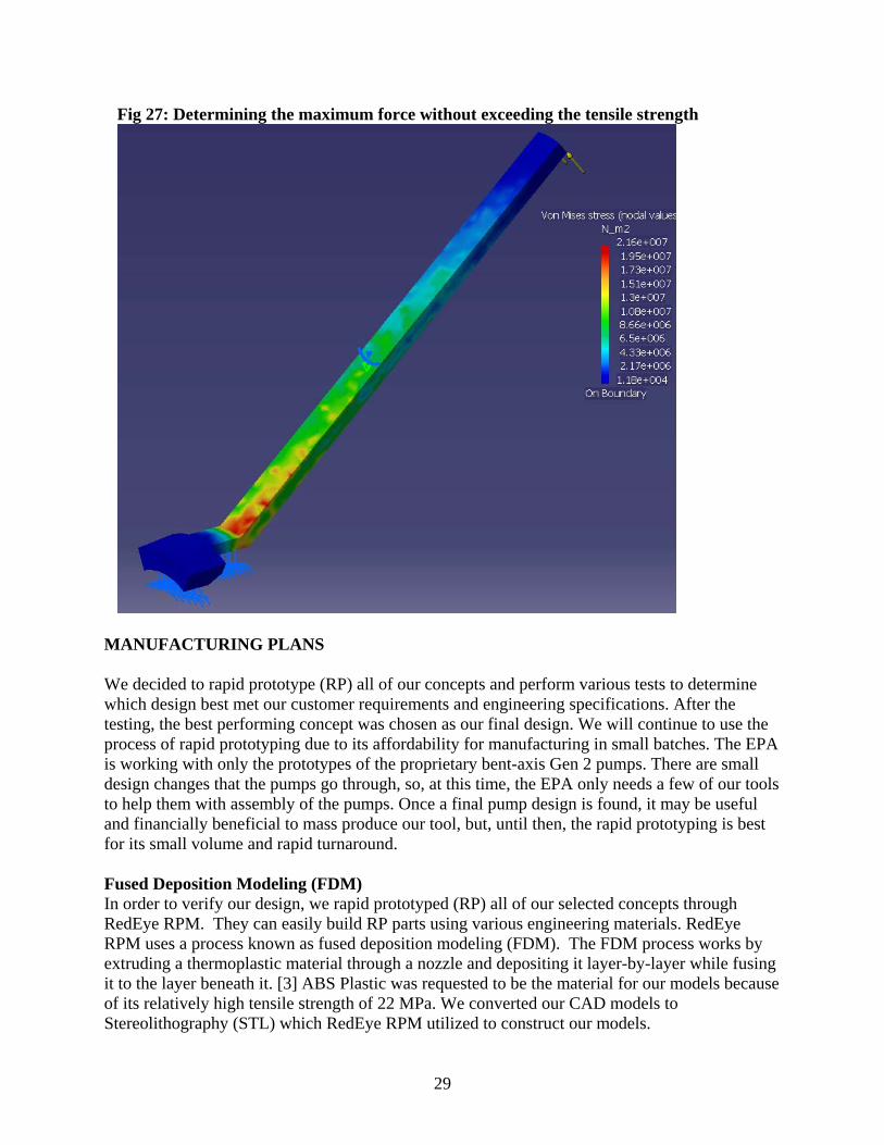
Final Design We decided to run FEA on our final design instead of the original stepped magnet, as the final design is a modified version of the original idea. Two analyses were done to cover most of the loading conditions that the tool will be subjected to. The first loading condition, shown in Fig. 26 on pg. 28, applies a force at the tip of the handle that is parallel to the handle. In this case, a minimum force required to remove the tool (37.34N, determined from static analysis) was applied to ensure durability under typical loading conditions. The maximum von Mises stress was found to be 1.73 MPa for the first case which results in safety factor of 12. The second loading condition, shown in Fig. 27 on pg. 29, applies a force perpendicular to the handle. In the second case, a maximum amount of force that could be applied without breaking the tool was determined via trial and error in FEA. This type of loading represents the worst case condition. The maximum perpendicular force was determined to be 3.38 N which results in von Mises stress of 21.6 MPa. This loading condition is very unlikely as the minimum perpendicular force

28
required to remove the tool was determined to be 1.18N in static analysis. So when the tool is subjected to more force than 1.18N it will simply detach from the couplers and the applied boundary conditions no longer apply. This validates that our tool will be durable even under various loading conditions.
Fig 26: FEA validates the durability of our final design
29
Fig 27: Determining the maximum force without exceeding the tensile strength
MANUFACTURING PLANS We decided to rapid prototype (RP) all of our concepts and perform various tests to determine which design best met our customer requirements and engineering specifications. After the testing, the best performing concept was chosen as our final design. We will continue to use the process of rapid prototyping due to its affordability for manufacturing in small batches. The EPA is working with only the prototypes of the proprietary bent-axis Gen 2 pumps. There are small design changes that the pumps go through, so, at this time, the EPA only needs a few of our tools to help them with assembly of the pumps. Once a final pump design is found, it may be useful and financially beneficial to mass produce our tool, but, until then, the rapid prototyping is best for its small volume and rapid turnaround. Fused Deposition Modeling (FDM) In order to verify our design, we rapid prototyped (RP) all of our selected concepts through RedEye RPM. They can easily build RP parts using various engineering materials. RedEye RPM uses a process known as fused deposition modeling (FDM). The FDM process works by extruding a thermoplastic material through a nozzle and depositing it layer-by-layer while fusing it to the layer beneath it. [3] ABS Plastic was requested to be the material for our models because of its relatively high tensile strength of 22 MPa. We converted our CAD models to Stereolithography (STL) which RedEye RPM utilized to construct our models.

30
Prototype Assembly After we received the prototypes, those requiring magnets had the magnets attached to them using epoxy. The adjustable magnetic tool was equipped with a pressed-in threaded aluminum sleeve and the accompanying screw. A bill of materials (BOM) for the prototypes is shown in Table 6 below. Table 6: BOMs for five selected prototypes
Quantity Part Description Purchased From Part Number Price (each) 1 Magnetic Adjustable Tool $47.42 1 Magnetic Adjustable Body RedEye RPM N/A $46.00 3 Magnet National Imports NSN0566/N40 $0.14 1 Screw Stadium Hardware H330095 $0.50 1 Threaded Al Sleeve Stadium Hardware N/A $0.50 1 Stepped Magnetic Tool $104.28 1 Stepped Magnetic Body RedEye RPM N/A $104.00 2 Magnet National Imports NSN0566/N40 $0.14 1 Moldable Putty Tool $27.00 1 Putty Toys ‘R Us N/A $2.00 1 Mold RedEye RPM N/A $25.00 1 Wand RedEye RPM N/A $60.00 1 “Bird of Prey” $79.42 1 Bird of Prey Body RedEye RPM N/A $79.00 3 Magnet National Imports NSN0566/N40 $0.14
The materials that were purchased include magnets, a screw, epoxy, and putty. We purchased Neodymium Grade 40 magnets from the National Imports website. The screw and sleeve were purchased at Stadium Hardware. Epoxy and putty will be purchased at a local hardware store. TESTING/VALIDATION – CHOOSING THE FINAL DESIGN The five prototypes were taken to the EPA and tested on the Gen 2 Pump to determine whether or not they functioned as intended. The testing was conducted by both the team and the sponsor, Dr. Mike Delduca. Both parties observed the time of assembly, the ease of assembly, functionality, repeatability, and durability of the prototypes. After the preliminary testing, we determined which design(s) best fit all of the customer requirements and engineering specs. Then we chose our final design, and additional improvements were made to its design based on our observations. Adjustable Magnetic Tool The Tool was designed to hold the female coupler steady while the male coupler is adjusted by either the putty or wand design. The tool is shown in use in Fig. 28 on pg. 31.

31
Fig. 28: The Adjustable Magnetic Tool Installed on the Gen2 Pump
As can be seen in Fig. 28 above, the adjustable magnetic tool performed just as expected, fitting well on the connecting rods, and securely holding the female coupler in place. This allowed the installer to focus on the male coupler only, and also freed up his/her hand to push on the backplate once the couplers are aligned for easier assembly. The adjustability of this tool proved useful in making fine adjustments to the placement of the female coupler. The tool was easy to remove once the CV joint was installed, and its repeatability in aligning the female coupler was very good. The shortcoming of this tool is the requirement of a second tool to align the male coupler. The “Bird of Prey” The Bird of Prey is similar to the adjustable magnetic tool in that it is designed to hold the female coupler steady while the male coupler is manipulated by either the wand or the putty design. The Bird of Prey can be seen in use in Fig. 29 on pg. 32.

32
Fig. 29: Bird of Prey Installed on the Gen2 Pump
As can be seen in Fig. 29 above, the Bird of Prey successfully aligned the female coupler to the correct position to allow installation. This freed a hand of the installer to allow him/her to push on the backplate to slide the couplers together once the male coupler was brought into position. This tool was also very easy to remove after installation. Shortcomings of this tool included the requirement of another tool to align the male coupler, and that it did not always perfectly align the female coupler. This was due to the changing angle of the connecting rods and the variability of the placement on the tool on the connecting rods. The Moldable Putty The moldable putty was designed to be used in conjunction with the adjustable magnetic tool or the Bird of Prey. The putty is shown installed on the Gen2 pump in Fig. 30 below.
Fig. 30: Moldable Putty Installed in Gen2 Pump
33
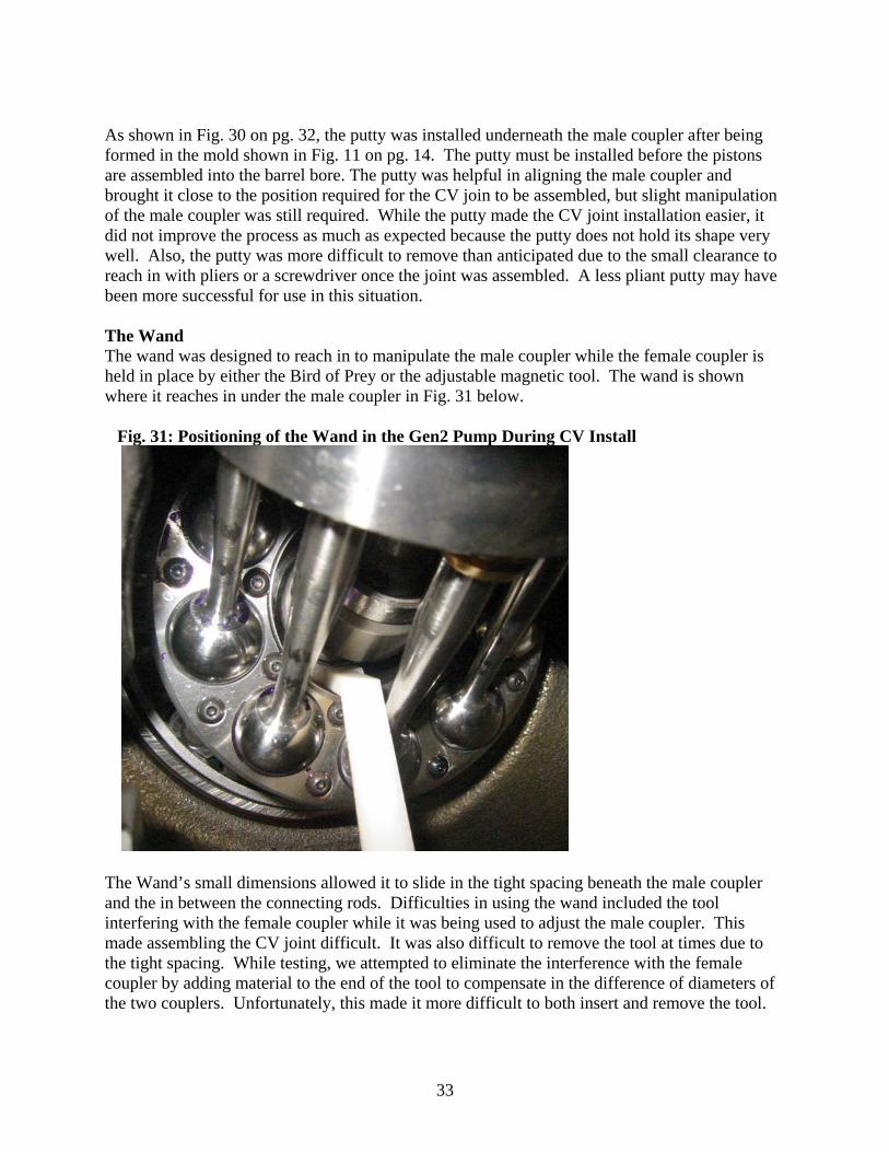
As shown in Fig. 30 on pg. 32, the putty was installed underneath the male coupler after being formed in the mold shown in Fig. 11 on pg. 14. The putty must be installed before the pistons are assembled into the barrel bore. The putty was helpful in aligning the male coupler and brought it close to the position required for the CV join to be assembled, but slight manipulation of the male coupler was still required. While the putty made the CV joint installation easier, it did not improve the process as much as expected because the putty does not hold its shape very well. Also, the putty was more difficult to remove than anticipated due to the small clearance to reach in with pliers or a screwdriver once the joint was assembled. A less pliant putty may have been more successful for use in this situation. The Wand The wand was designed to reach in to manipulate the male coupler while the female coupler is held in place by either the Bird of Prey or the adjustable magnetic tool. The wand is shown where it reaches in under the male coupler in Fig. 31 below.
Fig. 31: Positioning of the Wand in the Gen2 Pump During CV Install
The Wand’s small dimensions allowed it to slide in the tight spacing beneath the male coupler and the in between the connecting rods. Difficulties in using the wand included the tool interfering with the female coupler while it was being used to adjust the male coupler. This made assembling the CV joint difficult. It was also difficult to remove the tool at times due to the tight spacing. While testing, we attempted to eliminate the interference with the female coupler by adding material to the end of the tool to compensate in the difference of diameters of the two couplers. Unfortunately, this made it more difficult to both insert and remove the tool.

34
Stepped Magnetic Alignment Tool The stepped magnet tool was designed to align both couplers with magnets as its design incorporated the differences in diameter of the two couplers. The stepped magnet is shown installed on the Gen2 pump in Fig. 32 below.
Fig. 32: Stepped Magnet Design Installed on Gen2 Pump
As shown in Fig. 32, the stepped magnet design was successful in aligning both couplers of the CV joint for easy installation. A particular benefit to this design is that once both couplers are attached to the tool, the magnets will hold both the couplers and the tool in place. This allows both of the installer’s hands to be free to push on the backplate to complete the assembly. While the tool worked excellent once the couplers were attached to it, it was sometimes difficult to attach the couplers to the magnetic end of the tool. Testing Results In order to determine the best concept to choose for the final design, each tool was rated on a scale of one to ten in three important categories, shown in Table 7 on pg. 35.

35
Table 7: Testing Results and Scoring for Prototypes
As shown in Table 7 above, the designs were all scored individually on ease and speed of aligning the couplers and the ease of removing the tool. All tools were similarly durable, so this was left out of the calculation. The stepped magnet scored the highest of the prototypes, and it was agreed by both the team and the sponsor that this was the best tool. After choosing the best design, the stepped magnet was tested to ensure it met our customer’s most important requirement of assembling the CV joint in less than 2 minutes. The raw data for the trial runs can be viewed in Appendix D. A chart comparing the assembly time using the tool versus the current process is shown in Fig. 33 below.
Fig. 33: Comparison of Average CV Joint Assembly Times: Current vs. Using Stepped Magnet
0.6
7.0
15.0
0.0 5.0 10.0 15.0 20.0
Using SteppedTool
ExperiencedAssembler
InexperiencedAssembler
Time (minutes)
Design Stepped Magnet
Adjustable Magnet Bird of Prey Wand Putty
Ease of Alignment 6 N/A N/A 5 4
Speed of Alignment 5 N/A N/A 5 4
Ease of Removal 10 N/A N/A 7 3
Ease of Alignment 8 7 5 N/A N/A
Speed of Alignment 8 7 5 N/A N/A
Ease of Removal 10 10 10 N/A N/A
Design Combinations
Stepped Magnet
Adjustable Magnet/Wand
Adjustable Magnet/Putty
Bird of Prey/Wand
Bird of Prey/Putty
Total Score 47 41 35 37 31
Male Coupler
Female Coupler
± 0.37
36
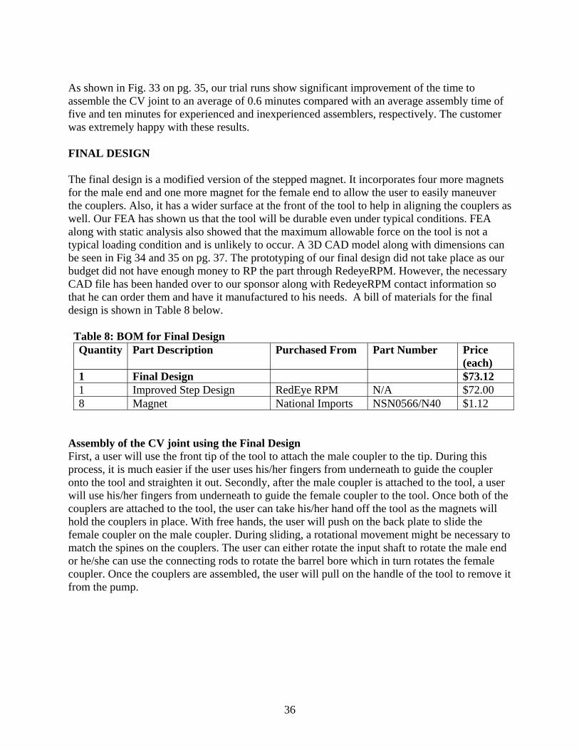
As shown in Fig. 33 on pg. 35, our trial runs show significant improvement of the time to assemble the CV joint to an average of 0.6 minutes compared with an average assembly time of five and ten minutes for experienced and inexperienced assemblers, respectively. The customer was extremely happy with these results. FINAL DESIGN The final design is a modified version of the stepped magnet. It incorporates four more magnets for the male end and one more magnet for the female end to allow the user to easily maneuver the couplers. Also, it has a wider surface at the front of the tool to help in aligning the couplers as well. Our FEA has shown us that the tool will be durable even under typical conditions. FEA along with static analysis also showed that the maximum allowable force on the tool is not a typical loading condition and is unlikely to occur. A 3D CAD model along with dimensions can be seen in Fig 34 and 35 on pg. 37. The prototyping of our final design did not take place as our budget did not have enough money to RP the part through RedeyeRPM. However, the necessary CAD file has been handed over to our sponsor along with RedeyeRPM contact information so that he can order them and have it manufactured to his needs. A bill of materials for the final design is shown in Table 8 below. Table 8: BOM for Final Design Quantity Part Description Purchased From Part Number Price
(each) 1 Final Design $73.12 1 Improved Step Design RedEye RPM N/A $72.00 8 Magnet National Imports NSN0566/N40 $1.12
Assembly of the CV joint using the Final Design First, a user will use the front tip of the tool to attach the male coupler to the tip. During this process, it is much easier if the user uses his/her fingers from underneath to guide the coupler onto the tool and straighten it out. Secondly, after the male coupler is attached to the tool, a user will use his/her fingers from underneath to guide the female coupler to the tool. Once both of the couplers are attached to the tool, the user can take his/her hand off the tool as the magnets will hold the couplers in place. With free hands, the user will push on the back plate to slide the female coupler on the male coupler. During sliding, a rotational movement might be necessary to match the spines on the couplers. The user can either rotate the input shaft to rotate the male end or he/she can use the connecting rods to rotate the barrel bore which in turn rotates the female coupler. Once the couplers are assembled, the user will pull on the handle of the tool to remove it from the pump.

37
Fig 34: 3D CAD Model of the Final Design
Fig 35: Dimensions of the Final Design
38
Future Improvements To further improve our tool, we have thought of a few changes we could make. Making the tool out of aluminum would give the tool more durability while keeping the tool relatively lightweight. However aluminum might mar the pump if it is accidentally forced into the drive plate by pushing on the backplate with too much force. Another change would be adding a knurled or rubber grip to the end of it to give the user a better grasp of the tool even if it were to be coated in hydraulic fluid from the working environment. PROJECT PLAN The goal of our team was to create a tool to aid the installation of the CV joint on a hydraulic pump. Research has been conducted on the best design for this application since late January. We have visited our sponsor to assemble the parts by hand to get a better understanding of what in particular makes it difficult, and from that experience we brainstormed concept tools that will ease these difficulties. Our team has decided that the best approach to solving this design problem will be to carry multiple tool concepts which will be prototyped. The prototypes were outsourced to RedEye RPM, a rapid prototyping company that created our parts out of ABS plastic. Once the prototype tools were created, we tested each tool by using it to install a CV joint on an actual pump. Based on the performance of each tool at this point, we chose our best tool, the stepped magnet, to refine. Upon reaching the final design, we discussed the options for producing it with our sponsor. He decided that the EPA will take on this task due to budget and time constraints. The EPA provided us with a budget of $400, and all work was completed within this budget. A detailed timeline is shown as a Gantt chart in Appendix B. CONCLUSIONS The goal of our project was to design and manufacture a tool to facilitate the installation of a CV joint in the bent-axis Gen 2 hydraulic pump for the EPA. The important engineering specifications considered were the material of the tool, number of parts, and dimensions of the tool. Taking these requirements and specifications into account, we narrowed our many design ideas down to five feasible options. Three designs incorporate magnets, one is of a wand design, and the other uses moldable putty. These five designs were prototyped and tested to determine the best performing tool. The chosen design (stepped magnet) successfully reduced the installation time to an average of 35 seconds, well below the required 2 minutes, and is easily removable once assembly is completed. Minor improvements were made to the stepped magnet design, and manufacturing of this final design will be carried out by Redeye RPM. ACKNOWLEDGEMENTS We would like to thank Dr. Michael Delduca and Dr. Andy Moskalik for their project proposal and their guidance throughout the semester. We would also like to thank Professor Kurabayashi for being very helpful whenever we needed his assistance.

39
REFERENCES [1] Gray, Charles “Hydraulic Hybrids”, Oct. 2006,
<http://files.harc.edu/Projects/Transportation/HydraulicHybridsGray.pdf> [2] Hall, Sabrina, David Lenss, Evan Quasney, and Kristina Tolbert. "ME 450: Design and
Manufacturing III." Apr. 2006. University of Michigan. 20 Jan. 2007, <http://www.engin.umich.edu/class/me450/W06_Projects/reports/proj8_report.pdf>.
[3] REDEYE RPM, INC., 2006, “What is Fused Deposition Modeling (FDM)™”,
<http://www.redeyerpm.com/FAQ.aspx#whatisfdm>
[4] Stratasys, Inc. 2005, “ABS,” <http://www.stratasys.com/uploadedFiles/North_America/Products/MatSpecs_ABS.pdf>
BIOS Michael Adams (Sponsor Contact) Michael hails from the great state of Minnesota, where he graduated from Hopkins High School, class of 2002. Michael came to Michigan purely because of the challenging academic program, so his loyalty towards the Minnesota Golden Gophers has constantly come under ridicule. Though he cheers for the Gophers in all instances against the Wolverines, (someone has to, right?) he did cast aside his allegiance in one case, where, as a driver, he helped the Michigan Solar Car Team win the 2005 North American Solar Challenge over Minnesota, who took 2nd. He later drove the car across the finish line of the 2005 Panasonic World Solar Challenge in Australia, where Michigan took 3rd. When Michael hasn’t been involved with Solar Car, he has been singing as a member of The Gentlemen (G-Men) a cappella group and he has been active in ASME, where he recently was the group’s Mr. Engineer nominee. Michael has been employed since his freshman year at the Museum of Paleontology, though he has also been a bus driver for the University, and most-recently he has been working at the Environmental Protection Agency’s National Vehicle and Fuel Emissions Lab in Ann Arbor. He foresees his future to be in Minneapolis or Chicago, though he’d be willing to entertain any job offer that comes his way. Megan Hasse (Co-Recorder) Megan was born and raised in Dearborn, Michigan with her parents, two older sisters, and younger brother. Megan has attended University of Michigan sporting events since she was a child and has always been a huge fan. After graduating from Dearborn High School in 2002, she could not wait to become a Michigan Wolverine herself. Her father as well as several of her uncles and cousins, graduated from the University of Michigan with engineering degrees. It was through these people that Megan became interested in mechanical engineering. She is currently a fifth-year senior, and is looking forward to graduating in April 2007. After graduation Megan hopes to begin working, but she currently does not have a specific company in mind. Besides being a student, Megan is a member of the University of Michigan women’s club volleyball team. Her team finished second place in the national tournament in 2006 and Megan was named an All-American. This year’s team is equally talented, and Megan is hoping to graduate as a national champion!

40
Nathan Johnson (Co-Recorder) Nathan was born in Detroit, Michigan where lived until 4 years of age. He then moved to Southfield, Mi where he graduated from Southfield High School in 2003. His first car was a 1996 Ford Mustang when he was 16. He quickly caught the bug for American muscle and when he was 17 he sold his first Mustang and bought a 1995 Ford Mustang GT. He has been modifying the body and engine ever since then. He started with rebuilding the engine with high performance cylinder heads and moved on to upgrading to the 5.8l 351w Windsor from the original 5.0l that came in the car. He has since went back to the 5.0l and added a custom turbocharger setup. With his mechanical abilities and his love for cars and motorcycles it seemed only natural for him to pursue a career in Mechanical Engineering. After graduating he plans on working in the automotive industry although at this time he has no specific company in mind. Taesoo Kim (Treasurer) Taesoo was born in Seoul, South Korea where he lived until 11 years of age. He moved to the United States in July of 1996 where he attended Middle School and High School on Long Island, New York, and graduated from the Class of 2003. He bought his first car (1996 Nissan 240sx) when he was 17 and developed a passion for the sport compact scene. With this passion, he decided to pursue a career in the auto industry with a mechanical engineering concentration. Taesoo still has a very keen interest in automobiles, has participated in Toyota cooperative internship for two rotations, and plans to work at Toyota Technical Center after graduating in December of 2007. In his free time he enjoys modifying his car. He has so far swapped the stock 2.4L engine in his car for a 2.0L turbocharged engine which he rebuilt and installed many performance upgrades such as a bigger turbocharger along with intake, exhaust, and fuel management system, which support the bigger turbo. He is currently building a cylinder head for his engine that will be capable of over 9000 RPM redline. His engine produces 320 RWHP as of today but his goal with the engine is for it to deliver close to 400 RWHP. Kirk Plawecki (Team Lead) Kirk Plawecki is a Michigan native, born and raised in Dearborn Heights with his parents Dave and Linda, and his older brother, Brent. He attended Divine Child grade school and high school, graduating in 2002. His father is a Michigan alumnus, and Kirk grew up cheering the Maize and Blue on to victory. Growing up in the motor city and living minutes away from Ford Motor Co. stemmed his interest in automobiles at a young age. He is most passionate about the Ford Mustang, and has been modifying and racing them since he owned his first at the age of 16. This subsequently brought about Kirk’s interest in the field of mechanical engineering, hoping to one day to contribute to the design of the vehicles he enjoyed every day. He entered the automotive industry by working for TRW Automotive as a Value Management Engineering Co-Op, and has spent three terms there thus far. While Kirk is still passionate about the automotive industry, he is exploring other options and is currently pursuing a career in consulting. When not at work or school, Kirk spends his free time in the winter months downhill skiing, and spends his summers on the golf course.

41
APPENDIX Appendix A: Additional Magnetic Concepts These are some additional magnetic concept ideas that we came up with. A.1: Stepped Magnetic Alignment Tool
A.2: Clip-on magnetic alignment tool
42
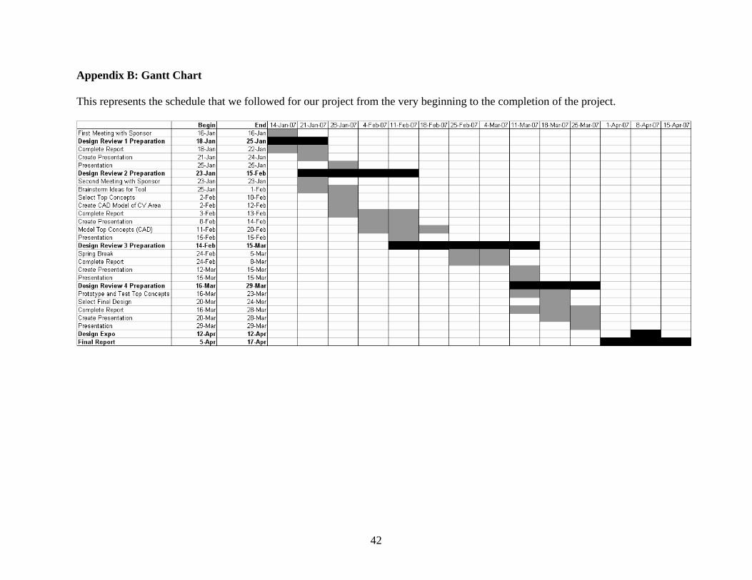
Appendix B: Gantt Chart This represents the schedule that we followed for our project from the very beginning to the completion of the project.
43
Appendix C: Pugh Chart To assemble this diagram, since we didn’t have a currently available product with which to compare, we set one of our final designs as the standard and compared the other four to it in terms of how we perceived each tool to fulfill our customer’s requirements.

44
Appendix D: Pump Assembly Trial Data This is a list of our test runs with our tool, with all units in seconds. Three of the group members and our project sponsor all completed assembly speed tests. Assembler T. Kim N. Johnson K. Plawecki M. DelducaTrial 1 (sec) 11.74 65.92 16.48 26.65Trial 2 (sec) 24.53 49.38 24.55Trial 3 (sec) 64.23 55. 7.Trial 4 (sec) 39.75 24.31 71.66Average (sec) 35.06 48.65 29.92Std Dev. 22.57 17.62 28.73
Overall Average 37.02Overall Std Dev. 21.99