Embed Size (px)
Citation preview
THATCH GUIDE:
PUBLISHED BY THE DIVISION OF BUILDING AND CONSTRUCTION TECHNOLOGYCSIR, PO BOX 395, PRETORIA, 0001
COPYRIGHT VESTS IN THE CSIR© 1998, CSIR, PRETORIA
BOUTEK REPORT NO BOU/E9806
DESIGN AND LAYOUT BY AFRICAN WATERMARK GRAPHIC DESIGN, PRETORIA
A GUIDETO GOOD THATCHING PRACTICE

I N D E X
1. Introduction2. Materials2.1 Common thatching grass2.2 Cape thatching reed3. Preparation3.1 Cleaning and bundling3.2 Combing3.3 Storing4. The thatcher’s tools4.1 A sickle4.2 The thatching spade or
“dekspaan”4.3 A straight needle4.4 A curved needle4.5 Climbing hooks5. Workmanship5.1 The thatching team5.2 Thatching5.3 Sways5.4 Spray layer5.5 Chimney stacks5.6 Hips5.7 Valleys5.8 Verges5.9 Ridges5.10 Use of conductors6. Characteristics of thatch6.1 Advantages6.2 Disadvantages7. Rainwater disposal8. Thatch decay9. Maintenance10. Design10.1 Roof structure10.2 Timber foundation
supports10.3 Effects of wind on thatch
roofing11. Lightning protection12. Fire safety of thatched
roofs12.1 Design and construction 12.2 Fire protection for
thatched structures
12.3 The regulatory environment13. Acknowledgements14. References
Appendix A: Guidelines for a typicalthatch roof specification
A1. Roof structureA1.1 GeneralA1.2 ConstructionA1.3 Structural timber or polesA1.4 Structural fixingsA1.5 LathsA2. RidgesA3. Poles and structural timberA3.1 Treatment of timberA4. Finishing of polesA5. ThatchA5.1 Thatching grassA5.2 Spray layerA5.3 Laying of thatchA5.4 FixingA6. Fire-retardant thatch treatmentA6.1 Fire-retardant coatingA7. ChimneysA8. Services
Appendix B: Rational fire safety designguidelines for thatched lapas
B1. GeneralB2. Thatch roofs covering a roof plan
area of less than 20 m2
B3. Thatch roofs covering a roof planarea of more than 20 m2
B3.1 SABS 0400 Part TB3.2 National Building Regulations T1
sub paragraph (2)B3.3 Rational design criteria

1 . I N T R O D U C T I O N
Thatch has been used as a roof cladding
material for many centuries. It creates an
aesthetically pleasing end result, well adapted
to the natural environment, and its popularity
has not diminished over time. Thatching is a
craft traditionally handed down from father
to son; consequently relatively little
documented information exists. It is to this
end that this guide is presented in an
endeavour to report concisely on the
present status of technology related to
good thatching practice.
Scope
This guide describes the basic techniques
employed in roof thatching. It identifies
certain problems that are commonly
encountered in both design and
construction and offers guidelines for
good thatching practice. The most
significant drawback of a thatched roof is
its vulnerability in the event of fire.
Practical fire-safety design principles,
developed after years of research, are
consequently briefly reported on in this
document. Guidelines for a typical thatch
roof specification are included in
Appendix A.
The construction of thatched lapas has
also become an area of major concern,
not only for most local authorities, but
also for insurance brokers. Since no
guidelines are given for the construction
of thatched structures in SABS 0400:1990
(Code of practice for the application of
the National Building Regulations),
guidance will also be given in this regard.
Guidelines for the fire-safe design of
thatched lapas are provided in Appendix B.
2 . M AT E R I A L S
Thatching makes use of materials that are
naturally obtainable, i.e. grass or reed. In South
Africa, only certain indigenous grasses are
normally used. Detailed information with regard
to all the grass species can be found in Frits van
Oudtshoorn’s book, Gids tot Grasse van Suid Afrika
(1991).
12.1 Common thatching grass
The most commonly used South African grasses with
their main geographical locations are listed below:
• Hyparrhenia hirta (generally known as common
thatching grass) - Natal Berg area, in
abundance;
• Hyperphilia dissoluta (commonly known as
yellow thatching grass) - Northern Province,
Mpumalanga, northern KwaZulu-Natal and
Swaziland;
• Thamnochortus insignis (or Cape thatching
reed, commonly known as “dekriet”,) -
Albertinia and Riversdale districts of the Cape;
• Hyparrhenia dregeana - Natal midlands and
Berg area;
• Hyparrhenia filipendula (commonly known as
fine thatching grass) - KwaZulu-Natal, Zululand
coastal regions;
• Thamnochortus erectus and Thamnochortus
specigerus (dekriet or thatch reed) - Cape
coastal regions;
• Chondropetalum tectorum - Cape area,
widespread; and
• Phragmites australis (Norfolk reed or swamp
grass, known locally as Umhlanga grass) -
widespread in South Africa.
Although commonly used in Britain, Norfolk reed has
not been widely used for thatching in this country, in
spite of its general availability. The type of grass
known as Tambookie grass (Tamboekie) is often used
in the rural areas for thatching, but there are coarse
varieties, with stalks thicker than 4 mm, that are not
considered suitable for thatching.
Natal thatching grass has a finer texture, when laid,
than the grass found in Mpumalanga and the Northern
Province, and is often preferred for this reason.
The stalks of thatching grass are normally hollow and
about 3 mm thick. Cape dekriet stalks, however, are
solid and about 3 to 4 mm thick. The quality of the
material improves with cultivation and regular
cutting. A question often asked is whether the quality
of the thatch is dependent on the way in which the
2
grass is harvested (cut), since some thatchers
consider the quality of material cut by hand
(with a sickle) to be superior to that cut with
a machine. The answer is no. The quality of
the thatch produced is the same; however,
hand-cutting will produce only about 50 to
100 bundles a day, whereas a mechanical
cutter and binder will process about 6 000
bundles a day.
Thatching grass is usually cut from mid-
winter to August, after growth has stopped
and the first hard frost has killed the
leaves. In areas where no frost occurs, the
only measure for determining whether the
grass is ripe and ready for cutting is
whether the grass plumes still contain any
seeds. Should this not be taken into
account (still lots of seeds) and the grass
be cut too early, this will impact not only
on the quality, but also the grass yield for
the following seasons. At the end of the
cutting season the remaining stubble and
undergrowth must be removed, either by
grazing or by burning.
2.2 Cape thatching reed
Cape thatching reed is a species of the
Restionaceae (reed) family, which is
widely distributed in the Albertinia and
Riversdale regions. This species, known as
Thamnochortus insignis is unisexual,
incorporating female as well as male
plants. The clumps of reed have a diameter
of 300 mm and more, and grow to a height
of 2.5 m. This is most commonly used in the
Cape regions because of availability but is
also used throughout South Africa.
The sandy area, or dunes, stretching
between the Gouritz River east of Albertinia
and the Duivenhoks River west of
Riversdale, from the coast in the south to
the sweet dunes near the N2 national road
that links Mossel Bay and Cape Town, is
thatching reed territory par excellence. The
thatching reed that grows mainly in the sand
dunes is consequently less abundant, and is
found in an area of about 2 000 km2. The lushest
reeds, however, grow in the sweet dunes that lie
below the chalk ridges as well as in the white sand in
front of the dunes.
Various species of the Proteaceae family that grow
mainly on the chalky ridges and sandy soil are also
found in this area and include Protea obtusifolia,
P. susannae and P.repens, the genera Leucospermum
muirii and L.cuneioforme, as well as different species
of leucadendrons, and the well-known heath, Erica
bauera.
As soon as the thatching reed has formed seed,
ripened and been dispersed, it is cut with sickles or
reed-cutting machines and spread out to dry,
transforming in colour to a rich gold.
Soon after the first rains, the tufts start growing again
and recover to such an extent that they can be re-
harvested after three years.
3 . P R E PA R AT I O N
3.1 Cleaning and bundling
After the grass has been cut and loosely bundled, each
bundle is shaken vigorously to dislodge all loose
material. The bundles are then cleaned by passing a
sickle through them, working from top to bottom. This
removes the remaining leaf growth from the lower two-
thirds of the stalks.
The grass is then regrouped into bundles about one to
1.5 m long and between 75 and 100 mm in diameter
(see Photograph 1). These bundles are each tied with
a thong of twisted grass or with twine and packed in
heaps (pyramid shape) about 2 m high and 2.5 to 3 m
in diameter at the base.
3.2 Combing
When the thatch or thatching reed is to be used for the
“spray layer” (or what is commonly referred to as the
spreilaag), immediately above the thatching battens,
where the underside will often be exposed in a room,
the material should be combed to ensure that the
stalks are perfectly clean. A comb is made by driving a
few 75 x 3.5 mm-diameter round wire nails into a
horizontal pole about 300 mm long. The nails are
spaced about 12 mm apart, in a straight line.
3
The bundles of grass are placed across the top of
the comb and pressed down so that the stalks
are separated by the nails. The bundle is then
pulled through the comb from the top to the
bottom end.
3.3 Storing
After combing, the bundles should be stacked
clear of the ground and under cover. Poor
thatch storage is portrayed in Photograph 2.
Bundles are normally baled for transport, in
batches of 10 to 20 bundles for manual
handling and 500 bundles for mechanical
handling.
4 . THE THATCHER’STOOLS
A thatcher in South Africa normally uses
five tools:
4.1 A sickle
This is used for hand cutting as well as for
cleaning the cut bundles.
4.2 The thatching spadeor “dekspaan”
This tool is known as a leggatt in Europe.
(See Photograph 3). This is usually a home-
made implement consisting of a board
about 150 x 200 x 30 mm thick, with a
handle on one flat side, rather like a
plasterer’s (wooden) float. Several metal
blades are secured to the other flat side.
These blades run across the 150 mm width
and are set at an angle of about 45° to the
bottom surface of the board, projecting
about 10 mm from it. This tool is used to
dress and shape the thatch in position.
4.3 A straight needle
When an assistant works on the underside of the
thatch, a straight needle, about 300 mm long, is
used to “stitch” the thatch to the roof battens
with thatching twine (treated sisal rope).
4.4 A curved needle
This is about 600 mm long and is used to stitch the
thatch to the roof battens, when the thatcher works
alone from the top of the roof.
4.5 CIimbing hooks
S-shaped climbing hooks are used to provide the
thatcher with a foothold when working on the roof
slope. The top hook, which is smaller than the others,
is hooked over the roofing battens and the lower hook
is then used as a stirrup.
An alternative method of providing a foothold is to use
poles, 100 mm in diameter. These may be supported on
two climbing hooks, or they may be wired to the roof
timbers with 4 mm diameter galvanised steel wire, as
seen in Photographs 4 and 5. At the apex of the roof, a
100 mm diameter ridge pole is fixed and another pole of
the same diameter is nailed on top of it.
5 . W O R K M A N S H I P
5.1 The thatching team
Normally, a thatching team consists of four men:
one to pass material from ground to roof level, two
thatchers working on the external roof surface,
and one working under the roof to assist those
working on the outside (Photograph 5). Such a team
can be expected to lay about 10 m2 of thatch in a
working day.
5.2 Thatching
Before each bundle is passed to the thatcher on the
roof, it is “butted” against a butting board, or on level
ground (Photograph 1), to ensure that the butt end is
even and that any sharp ends are blunted. The bundles
are normally thrown up to the thatcher. If the bundles
are less than 75 mm in diameter, it will be difficult to
throw them up to the roof because they will be too
light. This problem can be overcome by tying two
bundles together before they are passed to the
thatcher. However, this creates extra work for the
thatcher, who will usually prefer the bundles to be
about 100 to 125 mm in diameter, with a
circumference of about 300 - 400 mm.
4
Thatching is then started at one verge (footlog
level). The grass is used in bundles, as it was
cut, and laid on the roof with the butt end at
the lowest end. As each bundle is laid on the
roof, the thatcher cuts through the twisted
grass or twine that secures it. He places the
first bundle on the corner, at an angle of at
least 45°, thus exposing the butt end at the
eaves and starting at the verge (barge). As
he works the course towards the opposite
corner, the bundles are laid parallel to the
rafters. Each bundle in the first course, at
the eaves level, is secured to the second
batten with tar-treated sisal twine
(thatching twine) at 75 mm intervals.
Subsequent courses are secured by sways
(compaction rods) being laid on top of the
bundles and secured to the roof batten
below with thatching twine at 75 mm
intervals. As an alternative to the
traditional method, some thatchers prefer
to stitch each bundle direct onto the
thatching battens, not using any sways.
This method of fixing, however, creates
an undulating uneven surface that may
adversely affect the density, performance
and the durability of the thatch as a roof
covering.
The thatch is placed two bundles thick to
achieve a minimum thickness of 175 to
200 mm, depending on the diameter of
the thatch bundles. Each successive layer
conceals the sways that secure the
previous layer. The compaction of the
thatch and the possible sliding down of the
thatch layer over the roof structure are
very dependent on the tension of the twine
stitching. A roof with good compaction will
not only be more durable but will also slow
down the propagation and spread of fire
should the roof be ignited.
Good compaction of the thatch layer is also a
requirement for the effective fire protection
of any roof prior to the application of an
approved fire retardant.
5.3 Sways
In this document the sways or compaction rods
recommended for use refer to non-conductive sways
(either poplar or willow sticks, imported cane or a
group of four to five thatching reeds bundled
together). Wire or metal rods (conductive sways) are
most commonly used by thatchers in Southern Africa;
however, this practice is not recommended owing to
the associated lightning risk.
Poplar and willow sticks are commonly used but
Spanish reed (Arundo donax) [or] or basket willow
(Salax viminalis) might also be suitable. Some
thatching contractors use four to five strands of
dekriet for sways, while others use imported cane.
It should be noted, however, that the effect of
lightning must never be underestimated in the
construction of thatch roofs. The prerequisite for the
use of wire (conductive sways) for the compaction of
any thatch roof is the installation of a certified
lightning protection system that conforms to the
requirements stipulated in SABS 03:1985 (Code of
Practice for protection of structures against
lightning).
5.4 Spray layer
Before thatching proceeds, a layer of selected reed,
cleaned thatching stems or Cape thatching reed,
known as the spray layer (spreilaag), is spread evenly
on the roof battens to a thickness of about 5 to 8 mm
(enough to conceal the top layer). This imparts an
aesthetic appearance to the inside of the roof
covering.
A loose spray layer, cut to fit between the timber laths
on the inside of the roof at ridge level, is used to finish
off the ridge from the inside.
If no spray layer of selected reed is used, it is
recommended that ordinary clean thatching grass be
used as a bottom layer to create a neat surface on the
inside of the roof.
5
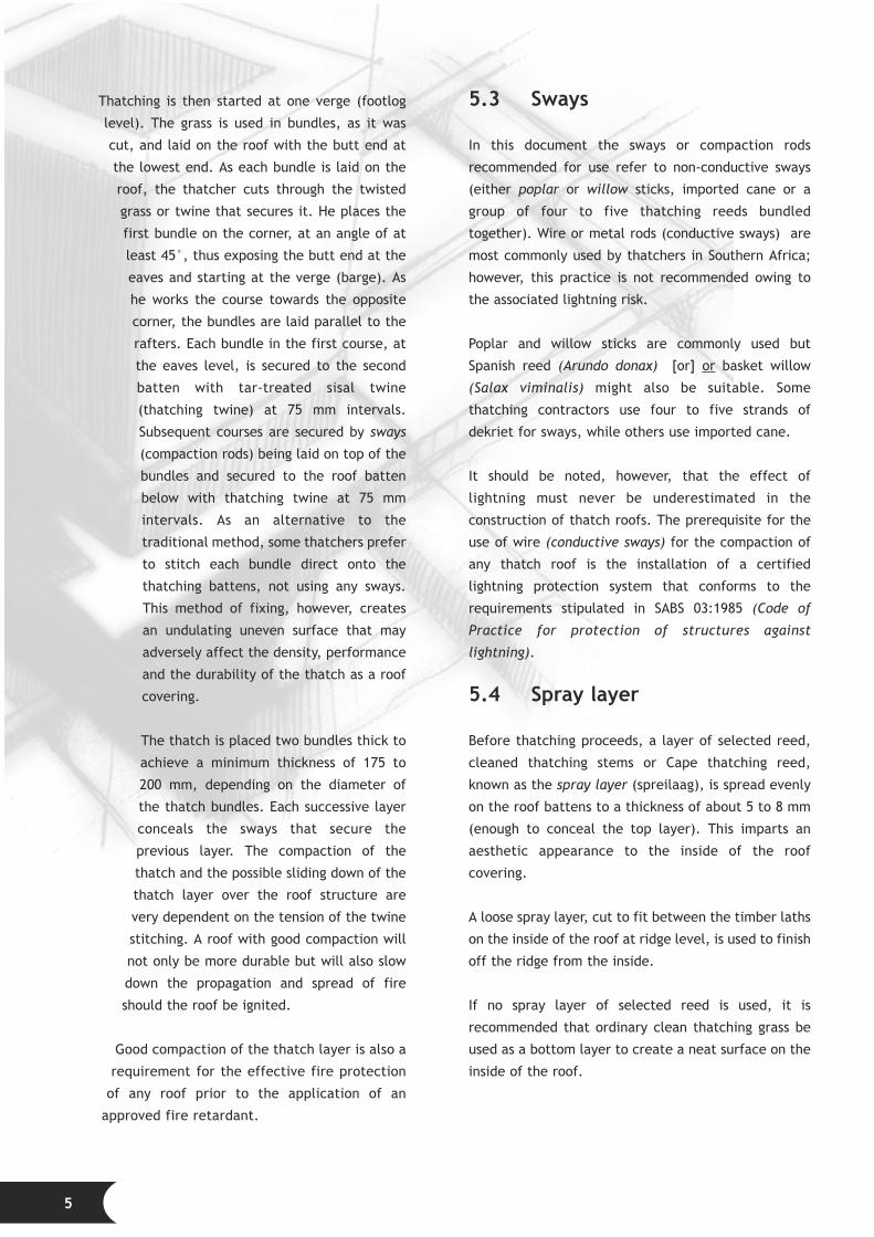
5.5 Chimney stacks
Special care is required where elements
such as chimney stacks and vent pipes
penetrate the roof plane. Such
features should be dressed/lined
with a sheet metal or fibreglass-
reinforced polyester flashing
under, between and over the
top surface of the thatch.
The width of the flashing
should be at least 250 to
300 mm. In case of
chimney stacks a secret
gutter is then formed against
the upper face of the chimney
and flashed against it. The higher
end of the sheet metal or fibreglass
gutter is dressed up under the thatch
to about 300 mm in width. (See
Figure 1.)
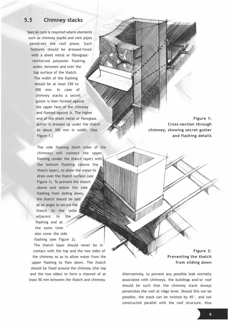
The side flashing (both sides of the
chimney) will connect the upper
flashing (under the thatch layer) with
the bottom flashing (above the
thatch layer), to allow the water to
drain over the thatch surface (see
Figure 1). To prevent the thatch
above and below the side
flashing from sliding down,
the thatch should be laid
at an angle to secure the
thatch to the laths
adjacent to the
flashing and at
the same time
also cover the side
flashing (see Figure 2).
The thatch layer should never be in
contact with the top and the two sides of
the chimney so as to allow water from the
upper flashing to flow down. The thatch
should be fixed around the chimney (the top
and the two sides) to form a channel of at
least 50 mm between the thatch and chimney.
Figure 1:Cross-section through
chimney, showing secret gutterand flashing details
Figure 2:Preventing the thatch
from sliding down
Alternatively, to prevent any possible leak normally
associated with chimneys, the buildings and/or roof
should be such that the chimney stack always
penetrates the roof at ridge level. Should this not be
possible, the stack can be twisted by 45°, and not
constructed parallel with the roof structure, thus
6

eliminating the problem of creating concealed
gutters and complicated flashings, etc, to allow
water to run off without spilling over the
flashings. (See Figure 3.)
Figure 3:Alternative
chimneydetail to
minimise waterleakage
5.6 Hips
Care should be taken when thatching roof
hips to ensure that the grass bundles at the
end of a hip plane run parallel to the hip
rafter. On each side of the hip, as the
course proceeds away from it, the bundles
are gradually orientated until they are
aligned perpendicularly to the battens. Care
should also be taken to ensure that the full
thickness of the thatch is maintained as it
progresses around the bend of the hip (see
Figure 4). The density of the thatch layer on
the hips tends to be lower than over the flat
sections and additional thatch may be
required. The thatch at the hips may require
more regular maintenance because of
accelerated weathering normally associated with
low density. The use of two hip beams, one at each
side of the corner, will provide an
acceptable alternative to the
problems caused by the 90°
angle. (See Figure 5.)
Figure 4:Section through hip showing a
single pole and the thinner thatchlayer over the corner
Figure 5:Section through hip showing a double pole
construction with a thicker and denser thatchlayer over a 135° corner
5.7 Valleys
These are formed by gradually orientating the
thatching bundles in each layer from the normal
vertical alignment direction to one parallel to the
valley. Additional material must be laid in the valley to
provide extra thickness to prevent water penetration
into the thatch layer and to provide a gradual sweep,
rather than a sharp bend. (See Figure 6.)
7
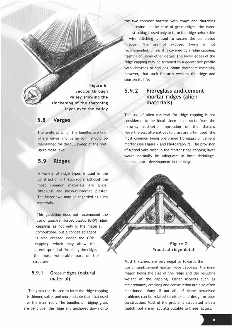
Figure 6:Section through
valley showing thethickening of the thatching
layer over the valley
5.8 Verges
The angle at which the bundles are laid,
where eaves and verge join, should be
maintained for the full sweep of the roof,
up to ridge level.
5.9 Ridges
A variety of ridge types is used in the
construction of thatch roofs, although the
most common materials are grass,
fibreglass and mesh-reinforced plaster.
The latter two may be regarded as alien
materials.
This guideline does not recommend the
use of glass-reinforced plastic (GRP) ridge
cappings as not only is the material
combustible, but a concealed space
is also created under the GRP
capping, which may allow the
lateral spread of fire along the ridge,
the most vulnerable part of the
structure.
5.9.1 Grass ridges (naturalmaterial)
The grass that is used to form the ridge capping
is thinner, softer and more pliable than that used
for the main roof. The bundles of ridging grass
are bent over the ridge and anchored down onto
the two topmost battens with sways and thatching
twine. In the case of grass ridges, the twine
stitching is used only to form the ridge before thin
wire stitching is used to secure the completed
ridge. The use of exposed twine is not
recommended, unless it is covered by a ridge capping,
flashing or some other detail. The lower edges of the
ridge capping may be trimmed to a decorative profile
with chevrons or scallops. Some thatchers maintain,
however, that such features weaken the ridge and
shorten its life.
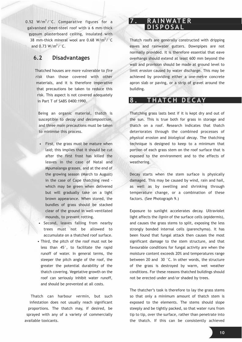
5.9.2 Fibreglass and cementmortar ridges (alienmaterials)
The use of alien material for ridge capping is not
considered to be ideal since it detracts from the
natural, aesthetic impression of the thatch.
Nevertheless, alternatives to grass are often used, the
most common being preformed fibreglass or cement
mortar (see Figure 7 and Photograph 7). The provision
of a steel wire mesh in the mortar ridge-capping layer
would normally be adequate to limit shrinkage-
induced crack development in the ridge.
Figure 7:Practical ridge detail
Most thatchers are very negative towards the
use of sand/cement mortar ridge cappings, the main
reason being the size of the ridge and the resulting
weight of the capping. Other aspects such as
maintenance, cracking and construction are also often
mentioned. Many, if not all, of these perceived
problems can be related to either bad design or poor
construction. Most of the problems associated with a
thatch roof are in fact attributable to these factors.
8

The advantages of a sand/cement mortar ridge
capping are that the material is non-
combustible, the formation of a concealed
space at the ridge level is avoided, and the
weight of the capping provides additional
compaction, preventing the thatch from
sliding out at the ridge.
The grass bundles at the ridge are either cut
to fit close to the uppermost ridge pole, or
the bundles are bent back under themselves
to form a knuckle against the ridge pole.
Even though this, or any other ridge detail,
is done very neatly, it will always look
incomplete on the inside. The use of a
spreilaag over the two ridge poles creates
an aesthetically pleasing detail when
viewed from the inside of the building (see
Photographs 8 and 11).
The following aspects should be
considered in the construction of an
acceptable and aesthetic mortar ridge
capping:
• a proper roof design and roof
structure;
• additional laths at the top of the roof;
• an additional layer of thatch at ridge
level (continuation of the flat, dressed
surface as high as possible);
• flatness of the roof at ridge level;
• detailed ridge drawings; and
• good thatch compaction (stitching and
tension of the twine).
The ridge is the most vulnerable part of a
thatch roof, as regards both water
penetration and fire. Particular care is
necessary to ensure that this feature of the
roof is absolutely watertight. Cement ridges
should always be used in conjunction with a
waterproofing membrane, to prevent leaking
in case of cracking of the ridge. Some
thatchers employ special techniques to seal
the cement ridge capping with a waterproof
membrane, or use a waterproofing membrane
under the cement capping to permit them to
grant a guarantee.
Concerns with regard to fire safety will be discussed
later, under a separate heading (see Section 12).
5.10 Use of conductors
The presence of steel or any type of conductor in the
roof structure presents a lightning conduction hazard
if the roof is not protected (as already mentioned). It
is therefore essential that the guidance given in SABS
03:1985 be followed rigorously to prevent any damage
from lightning. Under no circumstances should steel
pipes, cables or electric wiring be in direct contact
with the thatch. Electrical and other services
(telephone and TV) should always enter a building at
ground level and never be closer than one metre to the
thatch.
6 . C H A R A C T E R I S T I C SO F T H AT C H
The characteristics of thatch are described under the
headings of “advantages” and “disadvantages”.
6.1 Advantages
Local materials harmonise well with the landscape
surrounding their place of origin. Thatch, as a natural
material, will always blend well with any environment,
especially rural developments, creating a pleasing
architectural impression. After one season’s exposure,
however, the thatch will lose its fresh straw colour and
take on a dusty, grey appearance.
An ecological advantage to be gained from using
thatch is that it is produced by natural processes that
do not consume scarce and expensive energy
resources. The thatching process is a labour-intensive
activity and, therefore, of practical economic value
where unemployment among the lower income groups
is common.
A thatch roof functions as both an insulated roof and a
ceiling. The roof will ensure that the building is cool in
summer and warm in winter, since thatch has a high
insulation value. In technical terms the thermal
transmittance, or U-value, for thatch 150 mm thick is
0.65 W/m2/°C for downward heat flow (i.e. from
external sources), and 0.67 W/m2/°C for upward heat
flow (i.e. from internal sources). The corresponding
figures for 200 mm-thick thatch are 0.50 W/m2/°C and
9
0.52 W/m2/°C. Comparative figures for a
galvanised sheet-steel roof with a 6 mm-thick
gypsum plasterboard ceiling, insulated with
38 mm-thick mineral wool are 0.68 W/m2/°C
and 0.73 W/m2/°C.
6.2 Disadvantages
Thatched houses are more vulnerable to fire
risk than those covered with other
materials, and it is therefore imperative
that precautions be taken to reduce this
risk. This aspect is not covered adequately
in Part T of SABS 0400:1990.
Being an organic material, thatch is
susceptible to decay and decomposition,
and three main precautions must be taken
to minimise this process.
• First, the grass must be mature when
laid; this implies that it should be cut
after the first frost has killed the
leaves in the case of Natal and
Mpumalanga grasses, and at the end of
the growing season (March to August)
in the case of Cape thatching reed -
which may be green when delivered
but will gradually take on a light
brown appearance. When stored, the
bundles of grass should be stacked
clear of the ground in well-ventilated
mounds, to prevent rotting.
• Second, leaves falling from nearby
trees must not be allowed to
accumulate on a thatched roof surface.
• Third, the pitch of the roof must not be
less than 45°, to facilitate the rapid
runoff of water. In general terms, the
steeper the pitch angle of the roof, the
greater the potential durability of the
thatch covering. Vegetative growth on the
roof can seriously inhibit water runoff,
and should be prevented at all costs.
Thatch can harbour vermin, but such
infestation does not usually reach significant
proportions. The thatch may, if desired, be
sprayed with any of a variety of commercially
available toxicants.
7 . R A I N WAT E RD I S P O S A L
Thatch roofs are generally constructed with dripping
eaves and rainwater gutters. Downpipes are not
normally provided. It is therefore essential that eave
overhangs should extend at least 600 mm beyond the
wall and provision should be made at ground level to
limit erosion caused by water discharge. This may be
achieved by providing either a one-metre concrete
apron slab or paving, or a strip of gravel around the
building.
8 . T H AT C H D E C AY
Thatching grass lasts best if it is kept dry and out of
the sun. This is true both for grass in storage and
thatch on a roof. Research indicates that thatch
deteriorates through the combined processes of
physical erosion and biological decay. The thatching
technique is designed to keep to a minimum that
portion of each grass stem on the roof surface that is
exposed to the environment and to the effects of
weathering.
Decay starts when the stem surface is physically
damaged. This may be caused by wind, rain and hail,
as well as by swelling and shrinking through
temperature change, or a combination of these
factors. (See Photograph 9.)
Exposure to sunlight accelerates decay. Ultraviolet
light affects the lignin of the surface cells (epidermis),
and causes the grass stems to split, exposing the less
strongly bonded internal cells (parenchyma). It has
been found that fungal attack then causes the most
significant damage to the stem structure, and that
favourable conditions for fungal activity are when the
moisture content exceeds 20% and temperatures range
between 20 and 30 °C. In other words, the structure
of the grass is destroyed by warm, wet weather
conditions. For these reasons thatched buildings should
not be erected under and/or shaded by trees.
The thatcher’s task is therefore to lay the grass stems
so that only a minimum amount of thatch stem is
exposed to the elements. The stems should slope
steeply and be tightly packed, so that water runs from
tip to tip, over the surface, rather than penetrate into
the thatch. If this can be consistently achieved
10
through careful workmanship, over the entire roof
surface, decay will occur only on the outer
surface of the roof.
9 . M A I N T E N A N C E
With proper maintenance and re-thatching at
required intervals, a well-constructed thatch
roof should have a long lifespan. The original
design of the roof structure needs to be
adequate to take the additional load after
re-thatching. Apart from keeping the
surface of the thatch clear of creepers and
other vegetation, maintenance has to be
done on the thatch itself. Deterioration is
usually evident from the untidy
appearance of the covering.
The lifespan of the thatch will be
prolonged by regular inspections which
will indicate when “brushing” with a
thatching spade (leggatt) is required.
Re-dressing of the thatch cover (adding
of a new thatch layer) becomes
necessary when decay has reached the
stage when the fixings become exposed
on the surface. Once the fixings are
exposed, rainwater can be channelled
down through the thatch by running
down the stitching twine into the thatch
layer and into the building. Exposure of
the fixings will result not only in the
weathering of the twine stitching, but
also in the deterioration of the entire
roof cover when the compaction of the
stitching is lost.
Because thatch is a natural material, it will
deteriorate at a given rate, depending on
the environmental conditions for that area.
Inspections of the roof, in particular of areas
such as valleys, the areas under trees, and
areas with slopes of less than 45°, should be
carried out regularly to determine the
condition of the thatch layer. In general, the
rate of loss in thickness may be assumed to be
in the order of 20 mm to 25 mm in cover over
seven to nine years. For a 175 mm-thick thatch
layer, the thatching twine will generally be located
in the middle of the layer (about 80-100 mm below
the top surface) as the twine could eventually become
exposed after 20 years or so.
Re-dressing maintenance intervals are reflected in
Table 1, which assumes an initial thatch covering
thickness of 175 mm and a re-thatching thickness of
at least 100 mm. The maximum thickness of the
covering attained in the assumed 50-year lifecycle is
estimated at 255 mm. This thickness should be used
by designers in the analysis of the roof’s structural
stability.
All rotted thatching material should be completely
stripped out during maintenance and replaced with
new, tightly packed, mature material. The entire roof
should then be dressed by brushing prior to the
application of any new thatch layer.
Table 1: Typical thatch re-dressing maintenanceintervals
1 0 . D E S I G N
A thatch roof should have a minimum pitch of 45°. The
steep slope is needed so that water will run off from
the roof surface with minimum penetration into the
body of the thatch coat. At a pitch of less than 45° the
thatch will decay rapidly. Advantage may be taken of
this steep pitch to utilise the roof space for an extra
room.
Dormer windows, set into the roof slope, and
“eyebrow” windows at eave level should, for
maximum thatch durability, be avoided. They
invariably have a shallower pitch than the rest of the
roof, so that the thatch above them decays at a more
rapid rate. However, since they can be an appealing
11
Time Thatch in Add Total
(years) situ thatch thatch
(mm) (mm) (mm)
0 175 0 175
7 155 0 155
14 135 0 135
21 115 0 115
28 95 100 195
35 175 0 175
42 155 100 255
49 235 0 235
design feature, they are often included,
especially when the otherwise superfluous attic
space would be unused. The roof timber around
these windows must be designed to
accommodate the thickness of thatch (see
Photograph 10), and should slope as steeply as
possible, and never less than 40°. For dormer
windows, the bottom of the sill must be set
a minimum of 450 mm above the structural
roof level to accommodate the thatch
thickness and a suitable flashing.
As a general guide, the configuration of a
thatch roof should be as simple as possible.
The inherent ability of thatch to adapt to
freeform curved roof shapes allows
designers to develop less formal layouts
than they would for conventional roof
structures.
Flashings frequently result in
waterproofing problem areas. Features
that intrude in the roof plane should
consequently be avoided as far as
possible. Chimney stacks should be
designed to penetrate the roof plane at
the ridge (see Photograph 7), thus
avoiding the need for secret gutters. Soil
vent pipes are best located on external
walls, so that they penetrate the thatch
covering only near the eaves line.
However, modern plumbing systems do
have special vent valves, which eliminate
the need for soil vent pipes to penetrate
a roof.
In the design of multiple-level thatch roof
structures it is important to consider
rainwater discharge from these roofs. It is
essential to prevent a concentration of
rainwater discharging from a high-level roof
onto a thatch roof at a lower level.
10.1 Roof structure
Thatch should be placed to a thickness of
between 175 and 200 mm, resulting in an
approximate mass of 35 to 50 kg/m2. The roof
structure normally consists of eucalyptus poles
that have been chemically treated. Preservatives
such as Pentachlorophenol, CCA, borax or Tributyltin
oxide are suitable for such treatment. The use of fire-
retardant treated timber for the roof structure will
enhance the fire safety of the roof.
The thatching battens are usually treated
eucalyptus poles (battens or laths) with a minimum
diameter of 25 to 32 mm. Given the maximum
thatch covering thickness of 255 mm (see Table 1)
attained during the lifecycle of the roof, battens
should be spaced a maximum of 250 mm apart,
except at the eaves where the spacing between the
first three battens is 150 mm, and at the ridge
where the spacing between the last two battens is
also 150 mm. Batten spacings in excess of these
proposed may result in sagging of both the thatch
grass and the battens in the long term.
To limit batten sagging, rafter poles should be spaced
between 750 and 900 mm apart. The roof-framing
element sizes are dependent on many factors such as
roof span, loading (including wind), truss configuration
and support conditions. It is however proposed, from a
fire safety point of view, that poles with a diameter of
less than 100 mm be avoided, unless the design is done
by a structural engineer. All the roof-timber joints of
structural importance must be securely bolted
together.
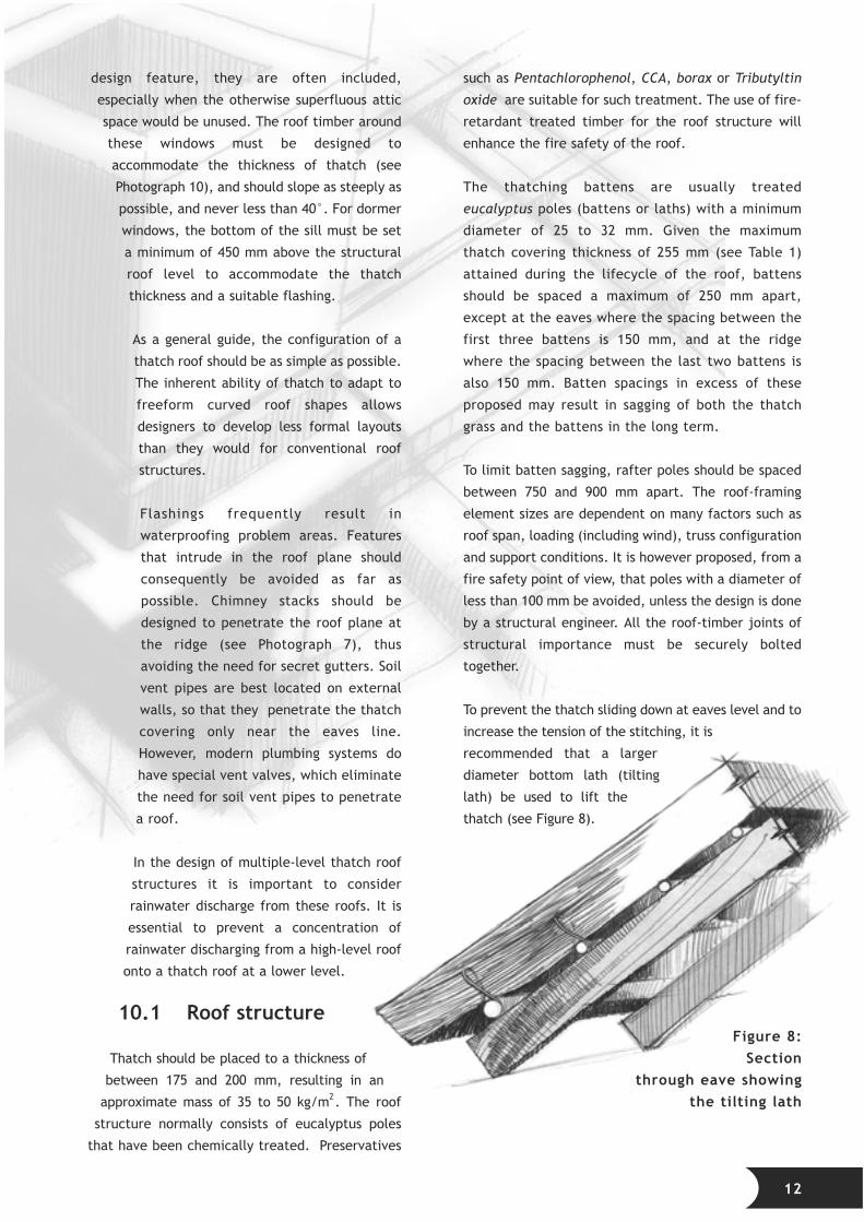
To prevent the thatch sliding down at eaves level and to
increase the tension of the stitching, it is
recommended that a larger
diameter bottom lath (tilting
lath) be used to lift the
thatch (see Figure 8).
Figure 8:Section
through eave showingthe tilting lath
12

Some popular truss configurations are illustrated
in Figure 9 and Photographs 11 and 12.
Figure 9:Some popular truss configurations
A great variety of ridge details exist in practice. The
ridge of a thatch roof is the most critical feature in the
case of fire as it represents the highest point in the
roof, to which the heat rises rapidly. Loss of the
integrity of the ridge construction inevitably results in
partial collapse of the roof structure, making fire-
fighting impossible from the inside of the building. The
most practical ridge detail, with regard to fire
resistance as well as ease of construction, is
illustrated in Figure 7 (see Section 5.9.2) and
Photograph 8. A typical hip detail is portrayed in
Photograph 13.
In an attempt to quantify the lateral restraint by an
external wall element on in-plane rafter forces, an
experiment was conducted at Boutek’s materials
and structural laboratory. Uncertainty about the
typical lateral restraint offered by external
double-leaf brickwork walls makes the designer’s
decision as to the most appropriate truss configuration
difficult.
Four double-leaf wall components, as portrayed in
Photograph 14, constructed from standard imperial
stock bricks with 100 mm-diameter eucalyptus poles
built in at 45°, were subjected to pull-out forces in the
plane of the rafter elements. The wall components
were restrained at the top and bottom in the
assumption of complete wall stability.
Only two of the four wall components were cured for
at least 10 days and two (one cured and one uncured)
were provided with a 4 mm-diameter wire anchor to
the depth of seven courses. The following conclusions
were drawn from the results of the experiment:
• Wire anchors contribute to the ultimate strength
of the assembly and result in a more ductile
mode of failure. Sudden, brittle failure occurred
in the wall components without wire anchors.
• The well-cured brickwork wall components
performed better than those not cured at all.
Given the wall stability assumed in the
experiment, the ultimate resistance to rafter
forces (in the plane of the rafter beams, tested
at 45°) was greater than 20 kN. An appropriate
factor of safety should be added to obtain a
permissible design load. Varying degrees of slip
took place before shear failure in the walls
occurred.
13

It may consequently be concluded that the lateral
restraint on rafter forces will generally be
controlled by the lateral restraint generated by
the overall wall stability and configuration.
10.2 Timber foundationsupports
Due to the decomposition of the internal
structure (“pipe rotting”) of timber poles in
contact with the ground (including treated
poles), it is recommended that poles be
founded and connected according to the
engineer’s details.
It is good engineering practice not to have
any structural timber in direct contact
with the ground or cast into concrete. The
use of concrete footings with special steel
connecting plates or sleeves is
recommended at all times.
As an alternative to concrete footings, an
approved protective sleeve around the
lower end of the pole may be used for
timber poles in contact with the ground.
This method should be used only for minor
structures and not for major structural
components requiring a life expectancy
exceeding 30 years.
10.3 Effects of wind onthatch roofing
It is Boutek’s opinion that, in general,
thatch roofs respond fairly well to extreme
wind conditions. This opinion is based on
experience gained in several site
inspections of areas devastated by wind.
This can largely be attributed to the overall
form of thatch roofs, in particular
• rounded-off edges and corners - as
opposed to being well defined (sharp) as
in other roofing systems;
• typical geometry which can be
approximated to the principle of “hipped
roofs”. Various research has shown that local
extreme wind pressures of hipped roofs are
significantly lower than those corresponding to
the mono- or duo-pitched roofs; and
• a roof slope of 45° (which minimises the risk of
uplift).
Photograph 15 depicts a luxury house with a thatch
roof, which was in the path of an F2 (on the Fujita
scale) tornado that struck the Midrand area on 21 April
1994. As can be seen, only minor roof-damage
occurred. As an indication of the severity of the storm,
all the water in a swimming pool located some twenty
metres from this house was sucked out .
1 1 . L I G H T N I N GP R O T E C T I O N
SABS 03:1985 (Code of Practice for the protection of
structures against lightning) sets out the principles
of lightning protection, and covers the installation of
a lightning protection system. The requirements for
air-terminal systems such as aerials, down-
conductors, earthing and materials are also given in
this code.
The basic principles of lightning protection require
that the following be provided:
• air terminals at strategic locations, so that the
installation is capable of intercepting and
withstanding a lightning strike while effectively
shielding adjacent objects that require
protection;
• low-impedance paths, termed “down-
conductors”, which can effectively conduct a
lightning discharge current from any air
terminal to the earth; and
• a low-impedance connection between the
down-conductor and the body of the earth, in
the form of an effective earth electrode, for
dissipating the lightning-discharge current.
The need for lightning protection is an assessment of
risk based on the following factors:
• the effective height of the structure, which is
related to the elevation of the highest point on
the structure compared to the elevation of the
surrounding area;
• an estimate of the local ground flash density
(average number of ground flashes per square
14
kilometre of ground per year at a given
location);
• the expected number of flashes striking
the structure per 100 years, which relates
to the capture area of the structure in
respect of lightning strikes; and
• the hazard category of the structure.
Consequential damage to a structure or
its contents, or injury to its occupants,
depends upon the nature of the contents,
or of the occupancy, or both.
An air terminal - comprising one or more
masts that cover the thatched-roof
structure or area to be protected - which
has the appropriate shielding angle will,
with the possible exception of a few weak
lightning strikes, successfully intercept
lightning strikes, and provide the highest
degree of protection. As a result of the
lightning discharge-current path being
kept from too close proximity to the
structure, a mast reduces the risk of
induced voltages in, and consequent
sparking between, conducting parts of
the structure.
A safe clearance between a mast (or a
catenary conductor strung between
masts) and the structure to be protected
by the mast (or the catenary conductor)
depends upon the following:
• the earth resistance of the earth
electrode of the mast, if it is not part
of a common earth electrode for the
masts and the structure;
• whether the structure is provided with
an electrode, which may be the
foundations; and
• whether the structure is connected to a
remote earth electrode, intentionally
or accidentally, through services which
may enter the structure either above or
below ground.
1 2 . F I R E S A F E T Y O FT H AT C H R O O F S
Numerous thatched dwellings have been lost in
Southern Africa because of the rapid spread of fire
through the roof. In most cases, the loss could have
been avoided or reduced if certain precautionary
measures had been adopted. The extent of potential
destruction in thatch-roof fires is portrayed in
Photographs 16 and 17.
The fire safety of a thatched building is dependent
upon a number of factors, including the design and
construction of the thatch structure, the provision of
additional fire-safety measures and good housekeeping
and maintenance. Fire-safety design is particularly
critical for a thatch structure, as its fire resistance is
dependent upon the quality of the thatch and the
stability of the structure. This is the essence of good
thatching practice.
The fire resistance of a thatch structure can, however,
be enhanced by the application of fire retardants
which retard the spread of flame, thus “buying time”
for escape and fire control measures.
The design of any building must comply with the
National Building Regulations. However, these
regulations were drawn up with certain common types
of building in mind and in the case of thatch structures
the code does not provide sufficient fire-safety design
guidelines.
It is the purpose of this section to address the
shortcomings of the code, to provide clear guidelines
for fire-safety design and good thatching practice, and
to create general awareness among homeowners of
fire-safety measures for thatch roof construction.
12.1 Design and construction
The fire resistance of a thatched structure is
dependent upon the quality of the thatch and the
stability of the structure. These critical aspects are
often either underestimated or misunderstood by
architects and engineers, despite the fact that their
designs have complied with the requirements of the
National Building Regulations. This is because there is
often a problem with the interpretation of the code
with respect to thatched structures and the code is
15

deficient concerning the fire-safe design of
thatched structures.
12.1.1 Good thatching practice
The quality of the thatch and the stability of
the structure determine the fire resistance of
a thatched building. The following guidelines
should be incorporated in the design and
construction of a thatch roof, to maximise
the structure’s ability to resist fire:
• The thatch density should be at least
35 to 50 kg/m2 for a thickness of 175
to 200 mm. The density of the thatch
is a very important factor in the rate
at which it burns. Densely compacted
thatch will burn slowly because it
reduces air flow and leads to oxygen
starvation.
• Sisal binding twine should be used in
preference to the polypropylene
variety as the latter is liable to melt
in the event of a fire.
• Lattice work must be of good quality
and soundly constructed.
• The structure as a whole must be well
designed, so as to be stable in the
event of a fire. (See Section 10.)
• In the case of large thatch roofs in
areas where lightning could pose a
problem, no wire must be used in the
roof construction and a lightning
conductor as specified in SABS 03:1985
must be provided. (See Section 11.)
12.1.2 Additional fire-safetymeasures for thethatch owner
The introduction of safety measures over
and above the minimum requirements of the
regulations is necessary to protect the
dwelling itself from fire. It is in the thatch
owner’s interest to be well informed of such
fire-safety measures for the protection of life
and property. Subsections 12.1.2 to 12.1.2.9
highlight some of the additional safety measures
detailed in the guidelines for a typical thatch roof
specification contained in Annexure A.
12.1.2.1 Lightning conductors
A lightning ground flash density chart has been
compiled for South Africa and Namibia, as shown in
Figure 1 of SABS 03:1985. Average values for specific
locations are given in Table 1 of this code (with the
lowest and the highest ground flash densities being 0.2
at Hermanus and Grabouw and 11.8 at Piet Retief,
respectively). Full protection is always recommended
for those areas at the upper levels of the scale.
Limited or no protection may be necessary for the low-
intensity areas, provided the roofs have been
constructed correctly and the thatch is treated with an
approved fire retardant that will effectively slow down
the rate of combustion should a fire start on the roof.
Lightning conductors should be installed to protect
thatched buildings or structures in accordance with
the recommendations contained in SABS 03:1985.
Furthermore, the installation of lightning protection
should be undertaken only by contractors competent
and qualified to do so.
It should be noted that this document does not favour
the use of wire or any other conductor for the securing
of thatch (although it is commonly used in South
Africa). Rather, it is recommended that a suitable
natural material be used for sways and the binding of
the thatch.
12.1.2.2 Chimneys
Chimney stacks should be constructed in such a way
that the outer faces in contact with the thatch do not
become hot. A full brick thickness (220 mm) is
necessary to satisfy this requirement. All mortar
joints in the stack must be properly filled. The top of
the stack must extend to at least a one-metre radius
from the highest point of the stack (closest to the
covering) and the roof covering (see Figure 10). A
spark-arrestor, fitted not less than 700 mm from the
top of the stack, should be provided. The spark-
arrestor typically comprises a 10 x 10 x 1 mm
(minimum) section of stainless steel wire mesh, across
the full width of the flue and securely built into the
flue around the edges (see Figure 11), or supported on
miId steel dowels. It is essential that chimney flues be
cleaned regularly to avoid an accumulation of soot,
which may ignite and generate sparks.
16

17
Figure 10:Typical section
through chimneyshowing the minimum height
above the thatch layer
Figure 11:Typical spark-arrestor
detail
12.1.2.3 Services
Electrical power supply and telephone
cables should enter the building by means
of underground ducts/conduits, and all
electrical wiring in the roof space should
be run in plastic conduiting, with all
junction boxes properly sealed.
12.1.2.4 Fire protection
The advantages of good thatching practice
cannot be overstressed both in terms of reduced
roof maintainence as well as fire safety. However, it
must be recognised that the two basic materials,
thatch and timber, are both combustible and need to
be protected by different methods.
(a) Fire protection of timber
Tests carried out by Boutek have shown that the
timber structure plays an important part in the
development of a thatched-roof fire. The timber not
only contributes to the fire load in the roof, but also
to the rapid spread of the fire in its early stages. The
thin battens that support the thatch burn through,
loosening the burning thatch. Once a portion of the
thatch has collapsed it creates an opening, allowing
free oxygen access to the seat of the fire: this leads
to vigorous burning. All of the timber used in the roof
should be treated with approved fire retardants to
inhibit ignition in accordance with the procedures
stipulated in Paragraph A3.1.2 in Appendix A.
(b) Fire protection of the thatch
The fire safety of a thatch roof is dependent upon the
structural stability of the roof under fire conditions.
The fire stability of the roof structure can be increased
substantially by using fire retarded timber and thatch.
It is recommended that the thatch be treated on both
sides with an approved fire retardant in accordance
with Section A4 of Appendix A.
12.1.2.5 The use of fire-protectivemembranes to restrict the flow of air
The rate of fire development in a thatch roof can be
greatly reduced by restricting the free flow of oxygen
to the fire. This can best be attained by means of
providing a non-combustible layer beneath the
thatch. If, for aesthetic reasons, a thatch finish is
1000 mm
required on the underside of the roof, the barrier
layer should be placed on a layer of thatch not
more than 6 mm thick.
In the case of a fire starting inside a house, the
protective layer will delay the burn-through
of the thatch. Because only a thin layer of
thatch will be directly exposed to fire on the
inside of the building (provided that the roof
timbers are fire-retarded) the fire in the
roof will be of a low intensity. The
protective layer will also delay the burning
thatch falling into the building.
Such layers must cover the total roof area,
including the eaves and ridges, if
maximum protection is to be obtained.
Special care must be taken to ensure that
adequate overlaps are provided, along
both horizontal and vertical joints in the
material used.
The use of impervious protective layers,
however, has certain disadvantages. Air
flow through the thatch is restricted and,
if the thatch becomes damp from rain or
condensation, high humidity levels may
develop which, in warm conditions, can
permit the growth of destructive fungi
and bacteria.
12.1.2.6 Fire-fighting facilities
A hosepipe of sufficient length to reach
every part of the roof and house, and
permanently attached to a garden outlet,
should always be available to assist fire-
fighting.
An extendable ladder, of sufficient length
to provide access to every part of the roof,
should be available at all times. In addition,
a long-handled metal rake should be
provided (in an easily accessible place) for
pulling down smouldering thatch from the
roof. The handle may be fitted with a suitable
clip to which the nozzle of the hosepipe can be
attached, thus improving the reach of the
water jet.
12.1.2.7 Good housekeeping
In addition to the requirements described in Section
12.1.1, combustible material should not be allowed to
accumulate near the building. A number of thatched
roofs have, in the past, been set alight as a result of
the burning of garden refuse in the vicinity of the roof
overhang.
12.1.2.8 General maintenance and “do’s” and“don’ts” for the thatch owner
The inherent danger of fire risks associated with
thatch roofs are sometimes exacerbated by the
following features:
• When thatch is old, it is often covered with
loose fibers which can easily ignite.
• It is possible that, when thatch is damp,
flammable gases may be generated.
• The incorrect use of conductors that may
penetrate the roof (do-it-yourself installations)
greatly increases the fire risk.
• The installation of a metal coping on the roof
and metal water or gas pipes in contact with the
thatch can increase the risk of fire associated
with lightning.
• Electric wiring (conductors) mounted in close
contact or just under the roof could also
increase the risk of fire. An example would be
the overheating of conductors caused by a
lightning strike, or short-circuiting in wiring due
to faulty electrical appliances or incorrect
electrical installations.
Apart from the protection of thatch roofs against
lightning by the installation of a mast terminal system,
consideration needs to be given to the following
additional good housekeeping features:
• Do not install antennas directly on a thatch
roof.
• Introduce electrical and telephone-cable
services at the ground level of the structure.
• Ensure there is adequate clearance between
the thatch and metal objects under it. Where
metals used in the construction of the roof are
not bonded and earthed, maintain a minimum
clearance of one metre between metals in the
roof and water pipes, vent pipes, tanks, gas
18

pipes, antennas, telephone and bell wires,
burglar alarms and electrical wiring and
conduiting.
12.1.2.9 General
Even when all these precautions have been
taken, the occupant of a thatched building
must always exercise caution when handling
open fires in or near the building (e.g. when
preparing for a barbecue, burning garden
refuse or discharging fireworks in the
vicinity).
12.2 Fire protection forthatched structures
Fire protection measures generally fall
into two categories; those that prevent
fires from starting in the thatch, and
those that reduce the ignitability of the
thatch and the roof structure.
The prevention of fires in thatch relates
to the fire-safety design of the thatched
structure. This includes a number of fire-
safety measures as well as the good
thatching practice already described in
Section 12.1.1.
Fire can reach the thatch from either the
inside of the building or from an external
source. The latter is the cause of most
thatch fires. Fire-protection measures that
reduce the ignitability of thatch include
the use of fire retardants.
This section highlights the factors that
influence the effectiveness of thatch
treatments and discusses the criteria for the
evaluation of fire retardants.
12.2.1 The use of fireretardants to treatthatch
Recent developments in fire-retardant
technology have produced a number of products
suitable for several distinct applications. These
include
• fire prevention;
• preservation and maintenance;
• internal fire protection only; and
• fire retardation, preservation and maintenance
(exterior and interior).
Any of the products referred to above should have
been the subject of evaluation by either Boutek or the
SABS, in which case a report detailing the results of
any such testing will be available. Such reports may
be used for advertising purposes only with the express
permission of the testing organisation.
Furthermore, it is important that the scale of the test
evaluation be taken into account when considering a
product for use on thatch, and in this regard a
comprehensive large-scale test is usually beneficial.
Thatched lapas fire-retarded with effective
treatments can be erected closer to boundaries than
would normally be permissible. The exact difference
in fire-safety distances is a factor of the efficacy of
the treatment being considered, such efficacy usually
being the subject of suitable fire tests on the
products.
12.2.2 Factors that will influence theeffectiveness of thatchtreatment
(a) As with most treatments, the efficacy of the
treatment is directly related to the quality and
condition of the thatch and to the stability of
the structure as a whole. New thatch roofs can
be treated without any pre-treatment, whereas
weathered roofs must be combed to remove
loose and weathered thatch. It is desirable to
treat thatch roofs as soon as possible after
construction.
(b) Any treatment should be applied to both the
interior and exterior surfaces, and should
penetrate the exterior thatch to a depth of at
least 65 to 75 mm. Sisal twine used to bind the
thatch is effectively protected by means of the
interior application, and twine so treated will
delay the dislodgement of the thatch during a
fire. During application it is necessary to
monitor the weather conditions. Depending on
the temperature and humidity, a treated roof
can be adversely affected should a heavy
19
shower occur within four to six hours of
application. Roofs affected by rain should
always be evaluated to determine whether
re-application is required.
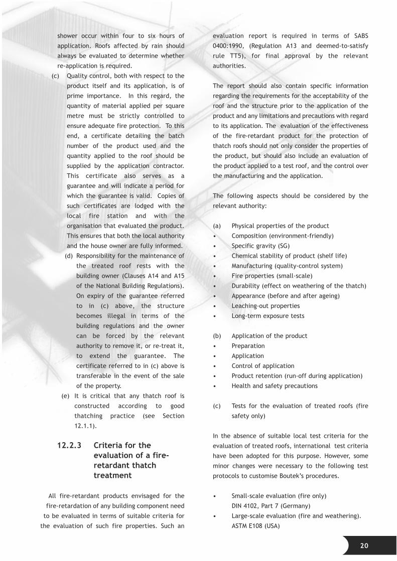
(c) Quality control, both with respect to the
product itself and its application, is of
prime importance. In this regard, the
quantity of material applied per square
metre must be strictly controlled to
ensure adequate fire protection. To this
end, a certificate detailing the batch
number of the product used and the
quantity applied to the roof should be
supplied by the application contractor.
This certificate also serves as a
guarantee and will indicate a period for
which the guarantee is valid. Copies of
such certificates are lodged with the
local fire station and with the
organisation that evaluated the product.
This ensures that both the local authority
and the house owner are fully informed.
(d) Responsibility for the maintenance of
the treated roof rests with the
building owner (Clauses A14 and A15
of the National Building Regulations).
On expiry of the guarantee referred
to in (c) above, the structure
becomes illegal in terms of the
building regulations and the owner
can be forced by the relevant
authority to remove it, or re-treat it,
to extend the guarantee. The
certificate referred to in (c) above is
transferable in the event of the sale
of the property.
(e) It is critical that any thatch roof is
constructed according to good
thatching practice (see Section
12.1.1).
12.2.3 Criteria for theevaluation of a fire-retardant thatchtreatment
All fire-retardant products envisaged for the
fire-retardation of any building component need
to be evaluated in terms of suitable criteria for
the evaluation of such fire properties. Such an
evaluation report is required in terms of SABS
0400:1990, (Regulation A13 and deemed-to-satisfy
rule TT5), for final approval by the relevant
authorities.
The report should also contain specific information
regarding the requirements for the acceptability of the
roof and the structure prior to the application of the
product and any limitations and precautions with regard
to its application. The evaluation of the effectiveness
of the fire-retardant product for the protection of
thatch roofs should not only consider the properties of
the product, but should also include an evaluation of
the product applied to a test roof, and the control over
the manufacturing and the application.
The following aspects should be considered by the
relevant authority:
(a) Physical properties of the product
• Composition (environment-friendly)
• Specific gravity (SG)
• Chemical stability of product (shelf life)
• Manufacturing (quality-control system)
• Fire properties (small-scale)
• Durability (effect on weathering of the thatch)
• Appearance (before and after ageing)
• Leaching-out properties
• Long-term exposure tests
(b) Application of the product
• Preparation
• Application
• Control of application
• Product retention (run-off during application)
• Health and safety precautions
(c) Tests for the evaluation of treated roofs (fire
safety only)
In the absence of suitable local test criteria for the
evaluation of treated roofs, international test criteria
have been adopted for this purpose. However, some
minor changes were necessary to the following test
protocols to customise Boutek’s procedures.
• Small-scale evaluation (fire only)
DIN 4102, Part 7 (Germany)
• Large-scale evaluation (fire and weathering).
ASTM E108 (USA)
20
12.2.4 General
The evaluation of a product to improve the fire
safety of thatch roofs should always look both
at the entire system and at the product alone.
The application and the control over the
application are of major importance when
certification is required in terms of SABS
0400:1990. Unless these are documented
properly, the system will not be acceptable
for approval by any local authority.
It is also necessary that the information
required, in terms of approval by the local
authority, be shown on the documentation
submitted for approval as this forms part
of the information considered for approval
in terms of SABS 0400:1990.
In terms of the National Building
Regulations, Part A, Administration,
A4(9), it is possible to cover all of the
above requirements and conditions in a
valid certificate issued by the Agrément
Board of South Africa. Once a product is
approved and covered by such a
certificate, the product is deemed to
satisfy all the relevant fire-safety
requirements in terms of the National
Building Regulations.
12.3 The regulatoryenvironment The National BuildingRegulations(SABS 0400:1990), Part T
The National Building Regulations (SABS
0400:1990), Part T, are applied by most
local authorities for the approval of thatch
roof construction. The regulations
recognise the high fire risk associated with
thatch roofs and are enforced in an
endeavour to prevent the spread of fire
between adjacent buildings. Two options are
offered by the regulations; the thatched
structure should either comply with the
deemed-to-satisfy rules reflected in Part T of
Section 3, or the structure should be the subject
of an acceptable rational design prepared by a
professional engineer or other approved competent
person.
12.3.1 SABS 0400:1990, Part T,Section 3
Sufficient distance must be allowed between
buildings to prevent fire spreading to the thatched
building from adjacent buildings, and vice versa. The
National Building Regulations (SABS 0400:1990 Part T,
rule TT2) prescribe minimum requirements in this
regard. Safety distances should be considered not
only for boundaries between buildings on separate
properties, but also between buildings/structures on
the same property.
12.3.1.1 Discussion of SABS 0400:1990, Part T
Problems have been experienced with respect to the
absence of reasonable fire safety guidelines for
thatched structures that comply with SABS 0400:1990
(Clauses TT2 and TT12). Inconsistencies within Part T
of the code have resulted in different interpretations
of required safety distances, boundary distances,
fire-division elements and protection of openings.
No structural guidance is offered by the code with
respect to rafter and lath spacing and timber
dimensions, despite the fact that the timber’s
structural design is fundamental to the effective
fire performance of the building. In the absence of
any clear guidelines, specifiers often resort to
relying on the experience of the thatching
contractor and specify on their plans “thatch roof
design in accordance with thatching contractor
details”. This clearly is an undesirable situation in
many instances.
12.3.2 Rational fire safety designprinciples
The fire code was drawn up with certain common
types of building in mind and it recommends that the
designer should resort to the basic principles of fire-
safety design for “non-standard” types of buildings. In
addition, it is advisable to use a rational fire design
approach for thatch roofs as this is building-specific
and relates to the entire fire-safety performance of
the building and its installations.
21
In any rational fire design the following points
must be taken into account when the fire safety
of any thatched construction is being
considered:
(a) From a fire-safety point of view, the
thatched structure is a habitable
dwelling or a non-habitable building
(lapa). Essentially, the fire hazard for
humans in a non-habitable building is
limited: it really only affects humans if a
burning lapa has an effect on an
adjoining structure - in most cases the
dwelling.
(b) The size of the thatched building has
a bearing on its effect, when burning,
on adjacent structures. The larger the
building, the larger the fuel source
and, in consequence, the greater the
risk of conflagration.
(c) A distinction is made between
buildings that have a roof-plan area of
less than 20 m2 and those larger.
(d) Boundary distances are determined in
relation to the intensity of the
radiation released from such a
structure at the boundary position.
12.3.4 Guidelines for atypical thatch roofspecification
Based upon the above rational fire-design
principles and due to the shortcomings of
the code as already discussed, Boutek, in
collaboration with the SABS, has developed
guidelines for specifications for thatch roof
construction. These guidelines are
contained in Annexure A, “Guidelines for a
typical thatch roof specification”, and
Annexure B, “Rational fire-safety design
proposals for thatched lapas”.
These proposals make provision for both new
and existing structures. They also contain
information on the various options, the
responsibility of the owner, and the
requirements of local authorities.
Boutek is of the opinion that the above guidelines
should be considered in the assessment of the fire risk
associated with thatched structures. The aim of these
guidelines is to provide a basis for a rational design in
order to ensure fire-safe design.
12.3.5 Existing thatch roofconstructions
The procedures for the fire protection of existing
thatch roofs are similar to the requirements for new
roofs, with the exception that the safety distances
stipulated in SABS 0400:1990 Part T, Clause TT12.2, in
many instances cannot be met.
These guidelines are concerned mainly with the
protection of new thatch roofs and do not cover
existing roofs. Measures to reduce the fire risk for
existing roofs that do not conform to the safety
distance requirements require special attention. The
only way to implement fire safety for these buildings
is either to remove the thatch roof, or portions of it,
or to change the fire properties of such a roof by
protecting it with an approved fire-retardant product,
to bring the risk down to an acceptable level. It should
be noted, however, that while the thatch layer may be
effectively fire-retarded, the timber can be treated
only on the surface with an approved fire-retardant
coating, which offers limited protection.
A distinction has to be made between residential and
non-residential buildings as the ultimate allowable
safety distances are different. A non-residential
building (lapa) is permitted within one metre of the
site boundary if it is protected, provided the roof does
not extend beyond the inside face of the boundary
wall. Residential buildings, on the other hand, have to
comply with the regulations as closely as possible,
with certain limited relaxations. The minimum
distance between boundary and the residential
building is three metres, provided that
• the thatch elevation facing the boundary is
completely shielded by a fire-separating wall
with adequate fire resistance, to the extent
that radiation from the burning thatch will not
impact on an adjacent building in a similar
position; and
• the thatch roof or roofs of the building have
been protected with an approved fire-retardant
to prevent the spread of fire, as contemplated
22

in Regulation T1 (a), (b) and (c) of SABS
0400:1990.
1 3 . A C K N O W L E D G E -M E N T S
These guidelines were compiled with the
collaboration of the following:
• SABS: Timber Division
• SABS: Fire Division
• The SA Thatchers’ Association
• The Division of Building Technology,
CSIR
• Technical information by Phillip de
Vos, Kobus Strydom and Chris Morris.
Illustrations: ARTINE cc
1 4 . R E F E R E N C E S
Laaly, H O (1992). The science and
technology of traditional and modern
roofing systems. Los Angeles, Calif. :
Laaly Scientific Publishing.
Long, K (1978). Introductory guide to
thatching. Pretoria : National Building
Research Institute, CSIR.
Van Oudtshoorn, F (1991). Gids tot grasse
van Suid-Afrika. Pretoria : Briza
Publikasies.
Rural Development Commission (1988).
The thatcher’s craft. London and Salisbury,
Wiltshire.
DIN 4102.7-1977. Fire behaviour of building
materials and building components;
roofings, definitions, requirements and
tests. Berlin : Institute for Building
Technology.
ASTM E 108-1993. Standard test methods for
fire tests of roof coverings. Philadelphia, Pa. :
American Society for Testing and Materials.
SABS 0163-2:1994. Code of practice for the structural
use of timber. Part 2, Allowable stress design. Pretoria
: South African Bureau of Standards.
SABS 03:1985. Code of practice for the protection of
structures against lightning. Pretoria : South African
Bureau of Standards.
SABS 0400:1990. Code of practice for the application
of the National Building Regulations. Pretoria : South
African Bureau of Standards.
SABS 05:1994. Code of practice for the preservative
treatment of timber. Pretoria : South African Bureau
of Standards.
SABS 457:1994, Parts 1, 2 and 3. Standard
specification for wooden poles, droppers, guardrails
posts and spacer blocks. Pretoria : South African
Bureau of Standards.
SABS 673:1987. Standard specification for mixtures of
copper-chromium-arsenic compounds for timber
preservation. Pretoria : South African Bureau of
Standards.
SABS 753:1994. Standard specification for pine poles,
cross-arms and spacers for power distribution,
telephone systems and street lighting. Pretoria : South
African Bureau of Standards.
SABS 754:1994. Standard specification for Eucalyptus
poles, cross-arms and spacers for power distribution
and telephone systems. Pretoria : South African
Bureau of Standards.
SABS 871:1967(1997). Standard specification for
boron timber preservatives. Pretoria : South African
Bureau of Standards.
SABS 1288:1994. Standard specification for
preservative-treated timber. Pretoria : South African
Bureau of Standards.
SABS 1783:1997. Standard specification for swan
softwood timber. Pretoria : South African Bureau of
Standards.
23
24
A P P E N D I X A
GUIDELINES FOR A TYPICALTHATCH ROOF SPECIFICATION
This specification includes fire-safety control
requirements for the construction of typical
thatch roofs on individual buildings. All
thatch roof construction must comply with
good thatching practice, as described in this
document.
This rational design approach has been
adopted by the Division of Building
Technology (Boutek) in order to overcome
some of the deficiencies in the SABS
1400:1990 code and to provide the
construction industry with a set of
guidelines for the sound construction of
thatch roofs.
A1. ROOF STRUCTURE
A1.1 General
All trusses, beams, rafters, timber posts,
bracing and roofing members, etc, should
be supplied and fixed in accordance with
the engineer’s design and details.
Generally the soffit of roof rafters and
thatching is not to project lower than
2 125 mm above the finished floor level
(FFL), unless specifically indicated.
Rafters and trusses should be evenly and
equally set out, on the centre line of the
building, as far as possible.
No roof timbers should penetrate the
chimney brickwork.
A1.2 Construction
All roof carpentry should be executed neatly
and be of a high standard.
The pitch of the roof should be 45°.
Rafters should be spaced at 750 to 900 mm centres.
The minimum roof overhang should be 600 mm,
measured to the wall.
Working drawings (construction details) of the roof
should be approved by the engineer.
A1.3 Structural timber or poles
All structural timber should comply with SABS
1783:1997, Part 2 and Part 4.
All poles should be of the eucalyptus species.
Roof construction poles should be at least 100 mm in
diameter at the thin ends, unless otherwise specified
and designed by the engineer.
Poles for columns or ring beams should have a
minimum thin-end diameter of 175 mm, or as
indicated by the engineer.
Other structural timber (bracing) should be in
accordance with the engineer’s design details.
Structural poles should comply with SABS 457:1994 in
terms of SABS 0163-2:1994, Code of practice for the
structural use of timber, Part 2, Allowable stress
design, Table 5: Grade stresses for round poles. Timber
poles for use in the construction of roofs are limited to
the species stipulated in SABS 753:1994 and SABS
754:1994.
All structural timber to be treated in accordance with
SABS 457:1994.
Exposed pole ends should be finished with nail plates
(minimum penetration depth 15 mm) to prevent
cracking, as stipulated in SABS 457:1994, Paragraph
4.2. Should it be necessary to cut the timber, involving
removing the existing end-plates, new end-plates must
be secured as soon as possible. The use of the new,
round end-plates is recommended.
A1.4 Structural fixings
Securely wrap 4 mm diameter (No 8 gauge) wire anchors
around rafters and nail the ends of the wire down. These
roof anchor wires should be built into the brickwork at
rafter-bearing centres, to a minimum depth of seven
brickwork courses, or as specified by the engineer.

25
All joints of structural importance in rafters and
trusses should be bolted down according to the
engineer’s details.
A1.5 Laths
Battens (laths) should be a minimum of 25
to 32 mm in diameter, spanning over at
least two spans (at least 1 500 to 1 800 mm
in length), and nailed to rafters with at
least 75 mm-long wire nails.
The bottom and top three laths at the
eaves and ridge should be fixed at 150 mm
centres.
The remaining laths should be spaced at
centres no more than 250 mm apart up to
the ridge of the roof, depending on the
length of the thatching grass.
A1.6 Timber foundationsupports
Timber supports to be founded as per
engineer’s detail.
A2. RIDGES
All ridge cappings should be formed with
sand/cement mortar that is trowelled
smooth. Lay a single layer of 250 µm
polyethylene sheeting over the thatch at
the ridge. Over the sheeting lay one layer
of 1 000 mm wide 12 mm x 12 mm
galvanised mesh on non-metallic spacers,
to elevate the mesh off the sheeting. Place
a second layer of mesh in the upper part of
the ridge capping, 15 - 20 mm from the top,
to prevent shrinkage induced cracking.
Form the ridge capping with a minimum
thickness of 75 mm, with a mortar mixture
of three parts sifted river sand to one part
Ordinary Portland Cement (OPC).
Generally, but dependent on the roof size,
the overall dimension of the ridge capping
should be 1 000 mm wide. The width of the
capping is dependent upon the condition and
shape of the roof at ridge level. It is therefore
recommended that an additional thatch layer be
secured at the top, to extend the smooth, dressed
surface as high as possible, leaving only a small flat
surface to be covered by the ridge capping.
All ridge cappings should be sealed. Clean surface
thoroughly with a soft brush and dress the entire
surface with an approved sealant, applying it
according to the manufacturer’s specifications and
details.
A3. POLES AND STRUCTURALTIMBER
A3.1 Treatment of timber detail
A3.1.1 Preservative treatment
All preservative treatment of timber must comply with
the SABS specifications listed below:
• SABS 1288:1994. Standard specification for
preservative treated timber (sawn structural
timber and laths).
• SABS 457:1994. Standard specification for
wooden poles, droppers, guardrails, posts and
spacer blocks.
• SABS 05:1994. Code of practice for preservative
treatment of timber.
The preservative treatment products have to comply
with the following product specifications:
• SABS 673:1987. Mixtures of CCA compounds for
timber preservation.
• SABS 871:1967 (1997). Boron timber
preservatives.
(a) CCA (copper-chrome-arsenic)
• CCA treatment is also known as celcure or
tanalith.
• CCA-treated timber is suitable for use in ground
contact for non-structural timber.
• All poles should be of the eucalyptus species.
• All timber poles should be vacuum-pressure-
impregnated with 6 to 12 kg approved CCA per
cubic metre of timber for H2 (no ground
contact) and H4 (ground contact) poles
respectively.
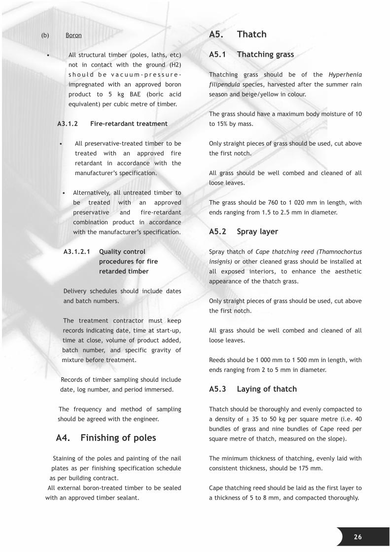
(b) Boron
• All structural timber (poles, laths, etc)
not in contact with the ground (H2)
s h o u l d b e v a c u u m - p r e s s u r e -
impregnated with an approved boron
product to 5 kg BAE (boric acid
equivalent) per cubic metre of timber.
A3.1.2 Fire-retardant treatment
• All preservative-treated timber to be
treated with an approved fire
retardant in accordance with the
manufacturer’s specification.
• Alternatively, all untreated timber to
be treated with an approved
preservative and fire-retardant
combination product in accordance
with the manufacturer’s specification.
A3.1.2.1 Quality controlprocedures for fireretarded timber
Delivery schedules should include dates
and batch numbers.
The treatment contractor must keep
records indicating date, time at start-up,
time at close, volume of product added,
batch number, and specific gravity of
mixture before treatment.
Records of timber sampling should include
date, log number, and period immersed.
The frequency and method of sampling
should be agreed with the engineer.
A4. Finishing of poles
Staining of the poles and painting of the nail
plates as per finishing specification schedule
as per building contract.
All external boron-treated timber to be sealed
with an approved timber sealant.
A5. Thatch
A5.1 Thatching grass
Thatching grass should be of the Hyperhenia
filipendula species, harvested after the summer rain
season and beige/yellow in colour.
The grass should have a maximum body moisture of 10
to 15% by mass.
Only straight pieces of grass should be used, cut above
the first notch.
All grass should be well combed and cleaned of all
loose leaves.
The grass should be 760 to 1 020 mm in length, with
ends ranging from 1.5 to 2.5 mm in diameter.
A5.2 Spray layer
Spray thatch of Cape thatching reed (Thamnochortus
insignis) or other cleaned grass should be installed at
all exposed interiors, to enhance the aesthetic
appearance of the thatch grass.
Only straight pieces of grass should be used, cut above
the first notch.
All grass should be well combed and cleaned of all
loose leaves.
Reeds should be 1 000 mm to 1 500 mm in length, with
ends ranging from 2 to 5 mm in diameter.
A5.3 Laying of thatch
Thatch should be thoroughly and evenly compacted to
a density of ± 35 to 50 kg per square metre (i.e. 40
bundles of grass and nine bundles of Cape reed per
square metre of thatch, measured on the slope).
The minimum thickness of thatching, evenly laid with
consistent thickness, should be 175 mm.
Cape thatching reed should be laid as the first layer to
a thickness of 5 to 8 mm, and compacted thoroughly.
26
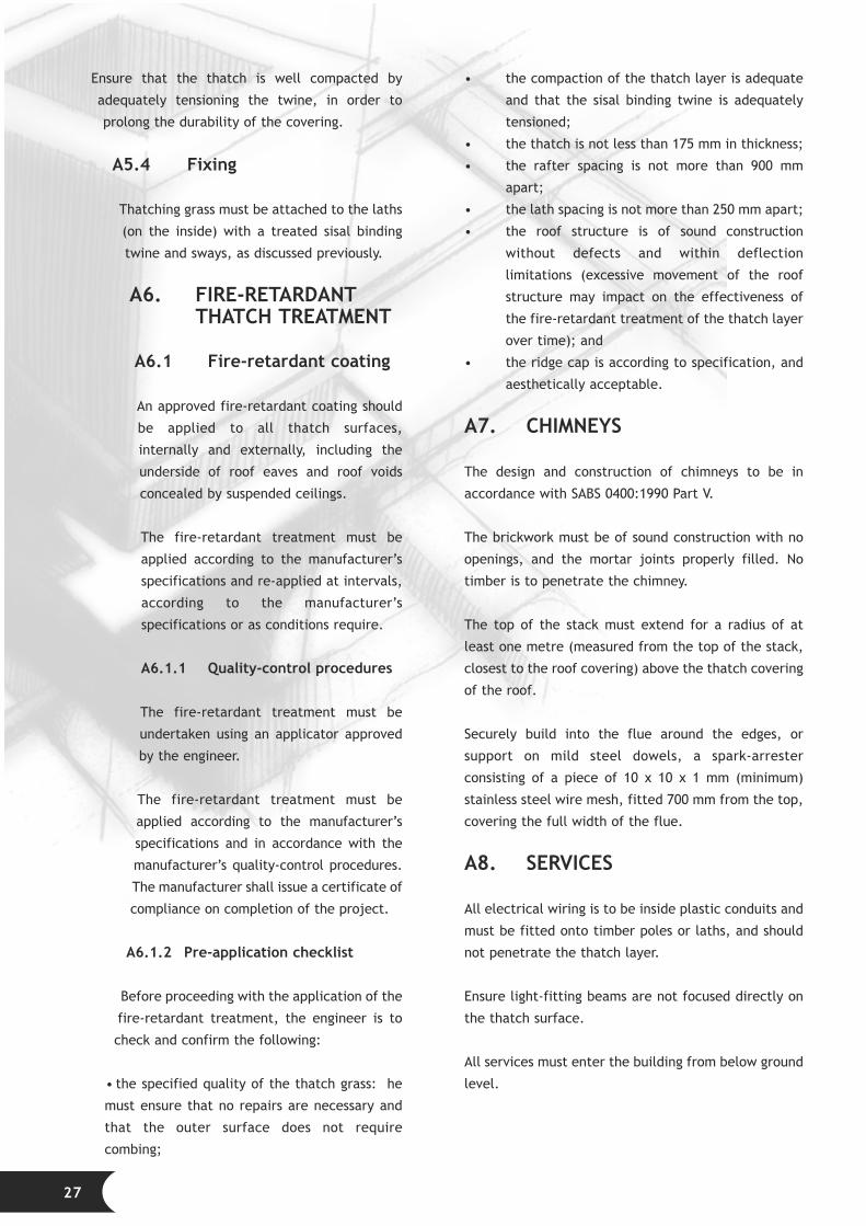
Ensure that the thatch is well compacted by
adequately tensioning the twine, in order to
prolong the durability of the covering.
A5.4 Fixing
Thatching grass must be attached to the laths
(on the inside) with a treated sisal binding
twine and sways, as discussed previously.
A6. FIRE-RETARDANTTHATCH TREATMENT
A6.1 Fire-retardant coating
An approved fire-retardant coating should
be applied to all thatch surfaces,
internally and externally, including the
underside of roof eaves and roof voids
concealed by suspended ceilings.
The fire-retardant treatment must be
applied according to the manufacturer’s
specifications and re-applied at intervals,
according to the manufacturer’s
specifications or as conditions require.
A6.1.1 Quality-control procedures
The fire-retardant treatment must be
undertaken using an applicator approved
by the engineer.
The fire-retardant treatment must be
applied according to the manufacturer’s
specifications and in accordance with the
manufacturer’s quality-control procedures.
The manufacturer shall issue a certificate of
compliance on completion of the project.
A6.1.2 Pre-application checklist
Before proceeding with the application of the
fire-retardant treatment, the engineer is to
check and confirm the following:
• the specified quality of the thatch grass: he
must ensure that no repairs are necessary and
that the outer surface does not require
combing;
• the compaction of the thatch layer is adequate
and that the sisal binding twine is adequately
tensioned;
• the thatch is not less than 175 mm in thickness;
• the rafter spacing is not more than 900 mm
apart;
• the lath spacing is not more than 250 mm apart;
• the roof structure is of sound construction
without defects and within deflection
limitations (excessive movement of the roof
structure may impact on the effectiveness of
the fire-retardant treatment of the thatch layer
over time); and
• the ridge cap is according to specification, and
aesthetically acceptable.
A7. CHIMNEYS
The design and construction of chimneys to be in
accordance with SABS 0400:1990 Part V.
The brickwork must be of sound construction with no
openings, and the mortar joints properly filled. No
timber is to penetrate the chimney.
The top of the stack must extend for a radius of at
least one metre (measured from the top of the stack,
closest to the roof covering) above the thatch covering
of the roof.
Securely build into the flue around the edges, or
support on mild steel dowels, a spark-arrester
consisting of a piece of 10 x 10 x 1 mm (minimum)
stainless steel wire mesh, fitted 700 mm from the top,
covering the full width of the flue.
A8. SERVICES
All electrical wiring is to be inside plastic conduits and
must be fitted onto timber poles or laths, and should
not penetrate the thatch layer.
Ensure light-fitting beams are not focused directly on
the thatch surface.
All services must enter the building from below ground
level.
27
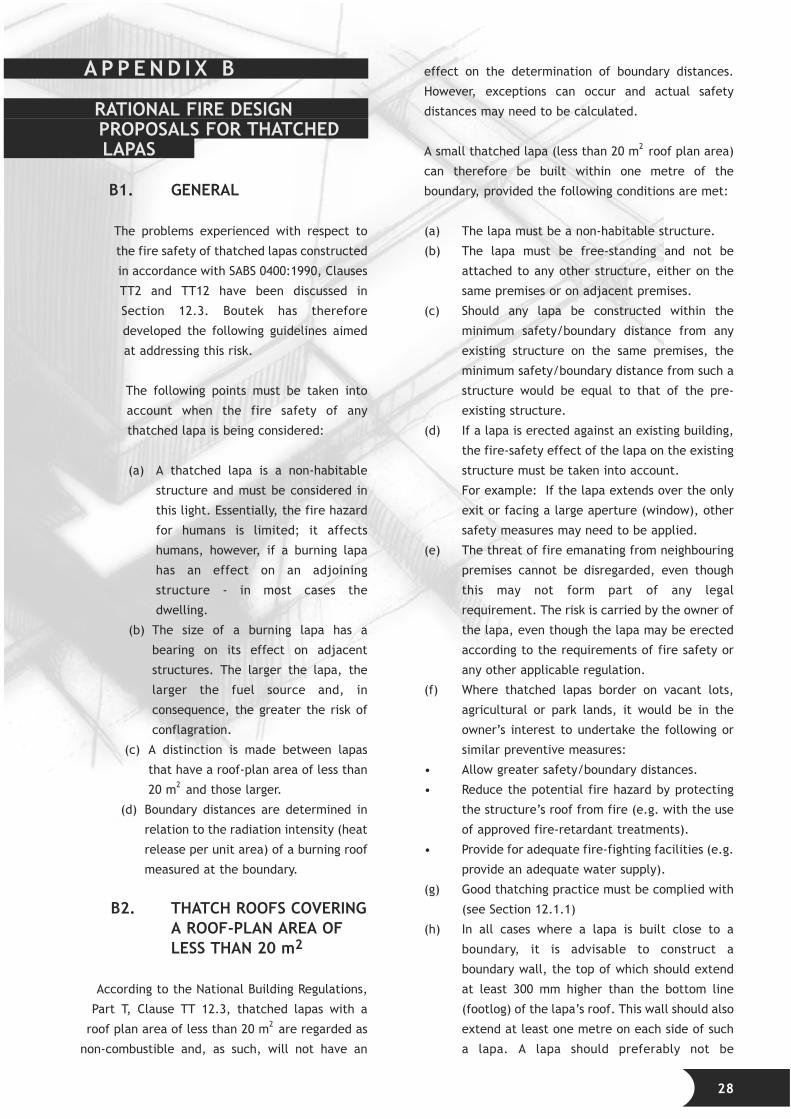
A P P E N D I X B
RATIONAL FIRE DESIGNPROPOSALS FOR THATCHEDLAPAS
B1. GENERAL
The problems experienced with respect to
the fire safety of thatched lapas constructed
in accordance with SABS 0400:1990, Clauses
TT2 and TT12 have been discussed in
Section 12.3. Boutek has therefore
developed the following guidelines aimed
at addressing this risk.
The following points must be taken into
account when the fire safety of any
thatched lapa is being considered:
(a) A thatched lapa is a non-habitable
structure and must be considered in
this light. Essentially, the fire hazard
for humans is limited; it affects
humans, however, if a burning lapa
has an effect on an adjoining
structure - in most cases the
dwelling.
(b) The size of a burning lapa has a
bearing on its effect on adjacent
structures. The larger the lapa, the
larger the fuel source and, in
consequence, the greater the risk of
conflagration.
(c) A distinction is made between lapas
that have a roof-plan area of less than
20 m2 and those larger.
(d) Boundary distances are determined in
relation to the radiation intensity (heat
release per unit area) of a burning roof
measured at the boundary.
B2. THATCH ROOFS COVERINGA ROOF-PLAN AREA OFLESS THAN 20 m2
According to the National Building Regulations,
Part T, Clause TT 12.3, thatched lapas with a
roof plan area of less than 20 m2 are regarded as
non-combustible and, as such, will not have an
effect on the determination of boundary distances.
However, exceptions can occur and actual safety
distances may need to be calculated.
A small thatched lapa (less than 20 m2 roof plan area)
can therefore be built within one metre of the
boundary, provided the following conditions are met:
(a) The lapa must be a non-habitable structure.
(b) The lapa must be free-standing and not be
attached to any other structure, either on the
same premises or on adjacent premises.
(c) Should any lapa be constructed within the
minimum safety/boundary distance from any
existing structure on the same premises, the
minimum safety/boundary distance from such a
structure would be equal to that of the pre-
existing structure.
(d) If a lapa is erected against an existing building,
the fire-safety effect of the lapa on the existing
structure must be taken into account.
For example: If the lapa extends over the only
exit or facing a large aperture (window), other
safety measures may need to be applied.
(e) The threat of fire emanating from neighbouring
premises cannot be disregarded, even though
this may not form part of any legal
requirement. The risk is carried by the owner of
the lapa, even though the lapa may be erected
according to the requirements of fire safety or
any other applicable regulation.
(f) Where thatched lapas border on vacant lots,
agricultural or park lands, it would be in the
owner’s interest to undertake the following or
similar preventive measures:
• Allow greater safety/boundary distances.
• Reduce the potential fire hazard by protecting
the structure’s roof from fire (e.g. with the use
of approved fire-retardant treatments).
• Provide for adequate fire-fighting facilities (e.g.
provide an adequate water supply).
(g) Good thatching practice must be complied with
(see Section 12.1.1)
(h) In all cases where a lapa is built close to a
boundary, it is advisable to construct a
boundary wall, the top of which should extend
at least 300 mm higher than the bottom line
(footlog) of the lapa’s roof. This wall should also
extend at least one metre on each side of such
a lapa. A lapa should preferably not be
28

29
constructed closer than one metre to any
boundary, this being the minimum distance
detailed in Table 2 of SABS 0400:1990, Part T,
Clause TT2.
(i) The foregoing is based on the
assumption that the lapa has a single
roof surface parallel to the boundary
and a roof pitch not exceeding 45°. Any
other roof configuration obviously
impacts on the surface area exposed to
the boundary. Such situations must
conform with further evaluations
(rational design from a fire safety point
of view) in accordance with the
National Building Regulations, Part T,
Regulation T1(2)(a).
B3. THATCH ROOFS COVERINGA ROOF-PLAN AREA OFMORE THAN 20 m2
Thatch roofs covering a lapa roof-plan
area in excess of 20 m2 are considered to
pose the same fire hazard as any other
roof constructed of combustible
materials, the major difference being
that lapas are non-habitable.
To ensure a fire-safe structure, one of two
building regulations should be applied,
namely:
(a) SABS 0400:1990, Part T, Clause TT12;
or
(b) Regulation T1 subparagraph (2) of the
National Building Regulations, which
includes the possibility of rational
design.
B3.1 SABS 0400:1990, Part T
This regulation simply stipulates that any
thatch roof covering a roof-plan area greater
than 20 m2 must be constructed at least 4.5
m from any boundary. This distance has been
determined with respect to the intensity of
radiation emanating from a burning roof and its
ability to ignite neighbouring structures. It
therefore follows that the same distance is
required between two or more buildings on the
same stand. If a thatched lapa has been erected
within the safety distance of 4.5 m, then - in common
with smaller lapas - further steps must be taken to
ensure adequate fire safety.
B3.2 National Building Regulations,Regulation T1, subparagraph (2)
If a thatched lapa with a roof plan area in excess of
20 m2 is erected within 4.5m of any boundary or
where the safety distance between the lapa and an
existing house is insufficient, then such cases should
form the subject of rational design.
B3.3 Rational design criteria
B3.3.1 If the lapa is within 4.5 m of aboundary
In this case Table 2 of SABS 0400:1990, Part T, Clause
TT2 should be consulted to calculate a realistic fire-
safety distance. Both local and foreign regulations
have been examined and, in conjunction with SABS
0400:1990, the following procedure has been
adopted:
(a) Determine the elevation (vertical) area of the
roof which is visible from the boundary or
neighbouring structure on the same stand,
assuming that there is a boundary wall of a
height at least that of the bottom edge of the
thatch roof. In the absence of a wall, the
elevation must be calculated from ground level
to the roof ridge.
Note: It is sound practice to erect a wall on the
boundary nearest the lapa which should extend
to at least one metre either side of the lapa.
Such a wall also serves as a heat shield at
ground level in the event of fire.
(b) Using the vertical elevation area of the roof,
determine the safety distance for a moderate
fire load (i.e. 25 to 50 kg/m2 timber equivalent
- the usual range in which a thatch roof falls).
(c) Now determine the centre point of the roof
slope (i.e. the centre between the roof ridge
and the roof’s bottom edge on the side closest
to the boundary).
(d) The safety distance determined in (b) above
should describe the required distance from the
boundary to the centre of the roof slope

(measured in (c)).
B3.3.2 A dwelling with a lapa on thesame stand
Refer to rules TT2.10 of SABS 0400:1990.
In this case, the safety distance is calculated
as the sum of the safety distances described
in Table 2 of SABS 0400:1990, part T, as
determined in (d) above.
Notwithstanding the above, the minimum
safety distance from any point of the roof
of a lapa to the boundary must not be less
than 1.0 m.
B3.3.3 Reduce the potential fireintensity of the lapa
This can be achieved in two ways:
• pull down the existing lapa and erect
it again to comply with fire-safety
requirements; or
• treat the lapa with approved fire
retardants to minimise the intensity
of any resultant fire.
30
Photograph 1Typical thatch bundle
Photograph 2Poor thatch storage
Photograph 3Thatching spade or leggatt
(“dekspaan”)
31

Photograph 4Eucalyptus poles on
climbing hooks
Photograph 5Typical two-man thatching
team with helper (oneteam member on the
inside)
Photograph 6Completing the thatching
at the ridge of the roof
32

Photograph 7Chimney (with flashings)
at ridge of roof
Photograph 8Inside view of ridge
Photograph 9Typical thatch decay in
need of maintenance
33
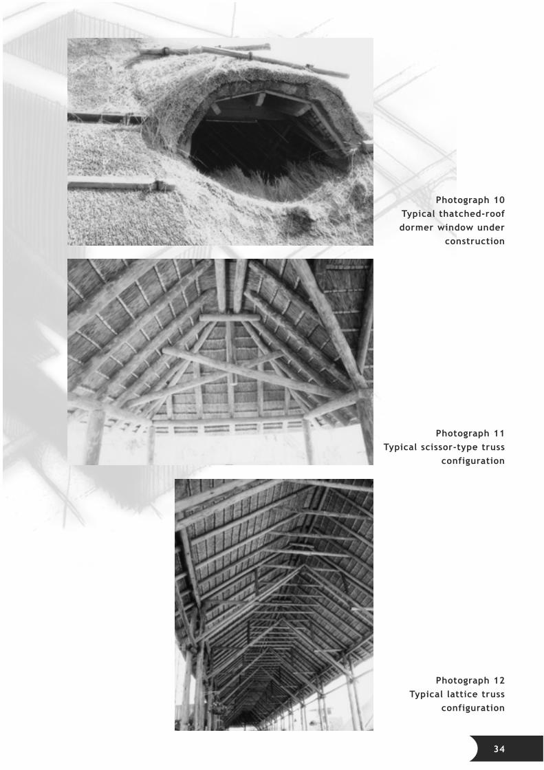
Photograph 10Typical thatched-roofdormer window under
construction
Photograph 11Typical scissor-type truss
configuration
Photograph 12Typical lattice truss
configuration
34

Photograph 13Typical thatched-roof hip
detail
Photograph 14Experimental test set-upto determine rafter pull-
out force from walls
Photograph 15A thatched-roof housestruck by the Midrand
tornado, April 1994
35
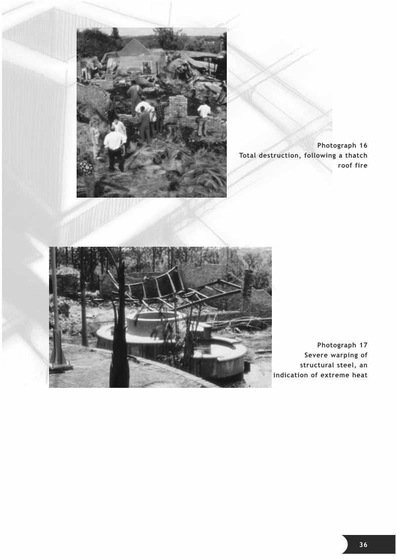
Photograph 16Total destruction, following a thatch
roof fire
Photograph 17Severe warping of
structural steel, anindication of extreme heat
36