Embed Size (px)
Citation preview

C O M M E R C I A L • I N D U S T R I A L • R E S I D E N T I A L
Design andInstallation
Guide
October 2011www.gastite.com
13133_Gastite_D+I_Guide_Winter2011_0_Cover1 5/30/12 10:20 AM Page 1
Important Lightning Safety Warning
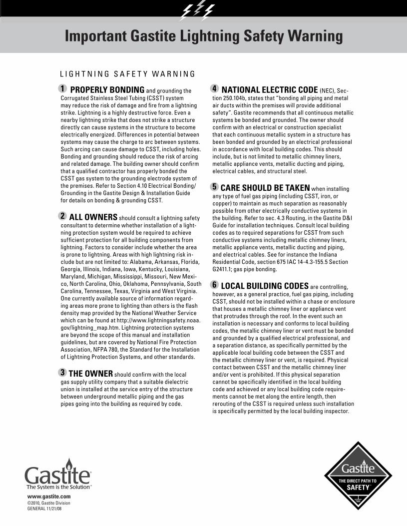
1 PROPERLY BONDING and grounding the Corrugated Stainless Steel Tubing (CSST) system may reduce the risk of damage and fire from a lightning strike. Lightning is a highly destructive force. Even a nearby lightning strike that does not strike a structure directly can cause systems in the structure to become electrically energized. Differences in potential between systems may cause the charge to arc between systems. Such arcing can cause damage to CSST, including holes. Bonding and grounding should reduce the risk of arcing and related damage. The building owner should confirm that a qualified contractor has properly bonded the CSST gas system to the grounding electrode system of the premises. Refer to Section 4.10 Electrical Bonding/Grounding in the Gastite Design & Installation Guide for details on bonding & grounding CSST.
2 ALL OWNERS should consult a lightning safety consultant to determine whether installation of a light-ning protection system would be required to achieve sufficient protection for all building components from lightning. Factors to consider include whether the area is prone to lightning. Areas with high lightning risk in-clude but are not limited to: Alabama, Arkansas, Florida, Georgia, Illinois, Indiana, Iowa, Kentucky, Louisiana, Maryland, Michigan, Mississippi, Missouri, New Mexi-co, North Carolina, Ohio, Oklahoma, Pennsylvania, South Carolina, Tennessee, Texas, Virginia and West Virginia. One currently available source of information regard-ing areas more prone to lighting than others is the flash density map provided by the National Weather Service which can be found at http://www.lightningsafety.noaa.gov/lightning_map.htm. Lightning protection systems are beyond the scope of this manual and installation guidelines, but are covered by National Fire Protection Association, NFPA 780, the Standard for the Installation of Lightning Protection Systems, and other standards.
3 THE OWNER should confirm with the local gas supply utility company that a suitable dielectric union is installed at the service entry of the structure between underground metallic piping and the gas pipes going into the building as required by code.
L I G H T N I N G S A F E T Y W A R N I N G
4 NATIONAL ELECTRIC CODE (NEC), Sec-tion 250.104b, states that “bonding all piping and metal air ducts within the premises will provide additional safety”. Gastite recommends that all continuous metallic systems be bonded and grounded. The owner should confirm with an electrical or construction specialist that each continuous metallic system in a structure has been bonded and grounded by an electrical professional in accordance with local building codes. This should include, but is not limited to metallic chimney liners, metallic appliance vents, metallic ducting and piping, electrical cables, and structural steel.
5 CARE SHOULD BE TAKEN when installing any type of fuel gas piping (including CSST, iron, or copper) to maintain as much separation as reasonably possible from other electrically conductive systems in the building. Refer to sec. 4.3 Routing, in the Gastite D&I Guide for installation techniques. Consult local building codes as to required separations for CSST from such conductive systems including metallic chimney liners, metallic appliance vents, metallic ducting and piping, and electrical cables. See for instance the Indiana Residential Code, section 675 IAC 14-4.3-155.5 Section G2411.1; gas pipe bonding.
6 LOCAL BUILDING CODES are controlling, however, as a general practice, fuel gas piping, including CSST, should not be installed within a chase or enclosure that houses a metallic chimney liner or appliance vent that protrudes through the roof. In the event such an installation is necessary and conforms to local building codes, the metallic chimney liner or vent must be bonded and grounded by a qualified electrical professional, and a separation distance, as specifically permitted by the applicable local building code between the CSST and the metallic chimney liner or vent, is required. Physical contact between CSST and the metallic chimney liner and/or vent is prohibited. If this physical separation cannot be specifically identified in the local building code and achieved or any local building code require-ments cannot be met along the entire length, then rerouting of the CSST is required unless such installation is specifically permitted by the local building inspector.
© 2008, Gastite Division, Titeflex CorporationGENERAL 11/21/08
www.gastite.comwww.gastite.com©2010, Gastite DivisionGENERAL 11/21/08
Important Gastite Lightning Safety Warning
13133_Gastite_D+I_Guide_Winter2011_0_Cover1 5/30/12 11:56 AM Page 3

Table of Contents
Gastite Division1116 Vaughn Parkway / Portland, TN 37148800.662.0208 / www.gastite.com / [email protected] iii
October 2011
SECTION 1.0 INTRODUCTION1.1 General User Warnings ..................................................................................................11.2 Limitations of the Guidelines..........................................................................................41.3 Standards, Listings and Codes ........................................................................................4
SECTION 2.0 SYSTEM DESCRIPTIONS & COMPONENTS2.1 System Descriptions........................................................................................................5
2.1.1 Gastite® System Description ..........................................................................................52.1.2 FlashShield™ System Description ..................................................................................6
2.2 Components....................................................................................................................72.2.1 Corrugated Stainless Steel Tubing ..................................................................................72.2.2 Fittings ......................................................................................................................92.2.3 Manifolds ................................................................................................................122.2.4 Modular Stub System ................................................................................................132.2.5 Mounting Hardware ..................................................................................................142.2.6 Pipe Support System....................................................................................................142.2.7 Strike Protection ........................................................................................................152.2.8 Shut-Off Valves and Quick Connects ............................................................................152.2.9 Tubing Cutters and Accessories ....................................................................................162.2.10 Bonding Clamps ......................................................................................................162.2.11 System Identification ................................................................................................162.2.12 Regulators ..............................................................................................................17
SECTION 3.0 SYSTEM CONFIGURATION3.1 Configuration ..............................................................................................................20
3.1.1 Introduction ..............................................................................................................203.1.2 System Requirements ..................................................................................................203.1.3 Reference Data for Proper System Sizing........................................................................203.1.4 Determining System Layout ........................................................................................213.1.5 Allowable Pressure Drop ............................................................................................233.1.6 Sizing Methods..........................................................................................................233.1.7 Modifying an Existing System ....................................................................................24
3.2 Sizing Procedures and Exercises ..................................................................................243.2.1 Sizing Examples ........................................................................................................243.2.2 Example 1 - Series System – 6"WC..............................................................................253.2.3 Example 2 - Parallel System – 6"WC..........................................................................273.2.4 Example 3 - Parallel System – 12-14"WC ..................................................................293.2.5 Example 4 - Dual Pressure System – 2 PSI Trunk and 8"WC Appliance Runs ................313.2.6 Example 5 - Multiple Manifold System ........................................................................333.2.7 Example 6 - Series System – 7"WC - Hybrid ................................................................353.2.8 Example 7 - Parallel System – 7"WC – Hybrid............................................................373.2.9 Example 8 - Summation Method for Parallel System – 7"WC – Hybrid ..........................393.2.10 Example 9 - Summation Method for Series System – 6"WC ..........................................413.2.11 Example 10 - Commercial Elevated Pressure Series System – 2PSI ..................................443.2.12 Example 11 - Commercial Hybrid System – 7"WC ......................................................46
SECTION 4.0 INSTALLATION PRACTICES4.1 General Provisions ........................................................................................................494.2 Field Fitting Assembly Procedure ................................................................................50
4.2.1 Gastite Field Fitting..................................................................................................504.2.2 FlashShield Field Fitting Assembly ............................................................................52
4.3 Routing ........................................................................................................................554.3.1 Vertical Runs ............................................................................................................554.3.2 Horizontal Runs........................................................................................................554.3.3 Installation Clearance Holes........................................................................................554.3.4 Concealed Fittings ....................................................................................................564.3.5 Modifications to Existing Systems ................................................................................574.3.6 Outdoor ....................................................................................................................57
13133_Gastite_D+I_Guide_Winter2011_1_TOC 5/30/12 10:16 AM Page iii
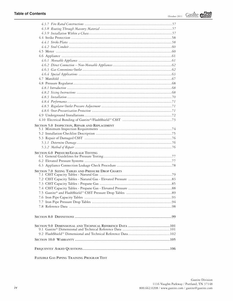
Table of Contents
Gastite Division1116 Vaughn Parkway / Portland, TN 37148
800.662.0208 / www.gastite.com / [email protected]
October 2011
4.3.7 Fire Rated Constructions ............................................................................................574.3.8 Routing Through Masonry Material ............................................................................574.3.9 Installation Within a Chase........................................................................................57
4.4 Strike Protection ..........................................................................................................584.4.1 Strike Plates ............................................................................................................584.4.2 Steel Conduit ............................................................................................................60
4.5 Meter ..........................................................................................................................60 4.6 Appliance ....................................................................................................................61
4.6.1 Moveable Appliance ..................................................................................................614.6.2 Direct Connection – Non-Moveable Appliances ..............................................................624.6.3 Gas Convenience Outlet ..............................................................................................624.6.4 Special Applications ..................................................................................................63
4.7 Manifold ......................................................................................................................674.8 Pressure Regulator........................................................................................................68
4.8.1 Introduction ..............................................................................................................684.8.2 Sizing Instructions ....................................................................................................684.8.3 Installation ..............................................................................................................704.8.4 Performance ..............................................................................................................714.8.5 Regulator Outlet Pressure Adjustment ..........................................................................714.8.6 Over-Pressurization Protection ....................................................................................71
4.9 Underground Installations ............................................................................................724.10 Electrical Bonding of Gastite®/FlashShield™ CSST ....................................................73
SECTION 5.0 INSPECTION, REPAIR AND REPLACEMENT5.1 Minimum Inspection Requirements ............................................................................745.2 Installation Checklist Description ................................................................................755.3 Repair of Damaged CSST ............................................................................................76
5.3.1 Determine Damage ....................................................................................................765.3.2 Method of Repair ......................................................................................................76
SECTION 6.0 PRESSURE/LEAKAGE TESTING6.1 General Guidelines for Pressure Testing........................................................................776.2 Elevated Pressure Systems ............................................................................................776.3 Appliance Connection Leakage Check Procedure ..........................................................78
SECTION 7.0 SIZING TABLES AND PRESSURE DROP CHARTS7.1 CSST Capacity Tables - Natural Gas ............................................................................797.2 CSST Capacity Tables - Natural Gas - Elevated Pressure ..............................................837.3 CSST Capacity Tables - Propane Gas ............................................................................857.4 CSST Capacity Tables - Propane Gas - Elevated Pressure ..............................................887.5 Gastite® and FlashShield™ CSST Pressure Drop Tables ................................................897.6 Iron Pipe Capacity Tables ............................................................................................937.7 Iron Pipe Pressure Drop Tables ....................................................................................947.8 Reference Data ............................................................................................................98
SECTION 8.0 DEFINITIONS ......................................................................................................99
SECTION 9.0 DIMENSIONAL AND TECHNICAL REFERENCE DATA ............................................1019.1 Gastite® Dimensional and Technical Reference Data ..................................................1019.2 FlashShield™ Dimensional and Technical Reference Data............................................102
SECTION 10.0 WARRANTY ....................................................................................................105
FREQUENTLY ASKED QUESTIONS............................................................................................106
FLEXIBLE GAS PIPING TRAINING PROGRAM TEST
13133_Gastite_D+I_Guide_Winter2011_1_TOC 5/30/12 10:16 AM Page iv
Section 1: Introduction
Gastite Division1116 Vaughn Parkway / Portland, TN 37148800.662.0208 / www.gastite.com / [email protected] 1
October 2011
SECTION 1.0 INTRODUCTION
Continued...
1.1 General User Warnings
Please note that there are specific differences between Gastite and FlashShield™ throughout this Design and InstallationGuide. Please take note of these differences as you read through the Guide.
The installation of Gastite® or FlashShield™ Flexible Gas Piping must be performed by a qualified installer who has successfullycompleted the Gastite®/FlashShield™ training program. The installer must meet all qualifications and requirements to installgas piping as required by the local administrative authority. Improper installation or operation of a Gastite® or FlashShield™
Flexible Gas Piping system may result in fire, explosion or asphyxiation.
This document provides the user with general guidance when designing and installing fuel gas piping using Gastite® orFlashShield™ Flexible Gas Piping. This guideline must be used in conjunction with all applicable building standards andcodes. In the event that there is a conflict between this guideline and local code the more stringent requirement will takeprecedence.
The use of fuel gas can be dangerous. Special attention must be given to the proper design, installation, testing and applicationof the gas piping system. Sound engineering practices and principles must be exercised, as well as diligent adherence to theproper installation procedures to ensure the safe operation of the piping system. All installed systems must pass customaryinstallation inspections by the local building official having authority prior to being placed into service.
Only the components provided or specified by Gastite as part of the Gastite®/FlashShield™ Flexible fuel piping system are tobe used in the installation. Use of components from other flexible gas piping systems other than those specified as part of theGastite®/FlashShield™ system is prohibited and may result in poor system performance and serious bodily injury or propertydamage. Where additions, repairs or replacements involve corrugated stainless steel tubing systems from manufacturers otherthan Gastite Division, the systems should be joined using standard pipe fittings at the interface.
This manual cannot take into account all situations or locations in which Gastite®/FlashShield™ Flexible Gas Piping will beinstalled. Accordingly, installers should also take into account guidance provided by the National Fuel Gas Code, ANSIZ223.1/NFPA-54, National Standard of Canada, Natural Gas and Propane Installation Code, CSA-B149.1, the UniformPlumbing Code, the International Code Series, the Federal Manufactured Home Construction and Safety Standards, 24 CFRPart 3280, the Manufactured Housing Construction and Safety Standards, ICC/ANSI 2.0 or the Standard on ManufacturedHousing, NFPA 501. Gastite Division shall have no responsibility for any misinterpretation of the information contained inthis guide or any improper installation or repair work or other deviation from procedures recommended in this manual,whether pursuant to local building codes or engineering specifications or otherwise.
Gastite Division makes no representation or warranty, and nothing contained in this manual shall imply that this manualcontains the best or the only approved method for installing corrugated stainless steel piping systems or that this manual’scontents are appropriate for all circumstances. In the event that there is a conflict between this guideline and local code themore stringent requirement will take precedence. Performance of accessory devices, such as pressure regulators and shutoff valves should be reconfirmed by contacting the accessory device manufacturer and receiving the latest technical dataon sizing, installation and performance.
13133_Gastite_D+I_Guide_Winter2011_2_SEC1 5/30/12 10:40 AM Page 1

Section 1: Introduction
Gastite Division1116 Vaughn Parkway / Portland, TN 37148
800.662.0208 / www.gastite.com / [email protected]
October 2011
1.1 General User Warnings (continued)
A Gastite®/FlashShield™ Flexible Gas Piping system offers advantages over other gas delivery systems because of its wall di-mensions and corrugated design. In contrast to rigid steel pipe, Gastite®/FlashShield™ does not require intermediate jointsin most installations because the tubing is capable of being installed in one continuous run, reducing not only the totalnumber of joints, but also the potential for leaks at joints. Gastite®/FlashShield™’s flexibility also affords more installationoptions because an installer can avoid existing obstacles, and it eliminates the repetitive measuring, cutting, threading andjoint assembly that are common with installation of rigid steel piping systems. Gastite®/FlashShield™’s flexibility offerseven further safety advantages in geographic areas that are prone to seismic activity because the tubing is able to move asthe ground or the structure shifts.
While Gastite®/FlashShield™ provides significant advantages over more rigid gas delivery systems, its flexible design maymake it more likely than steel pipe to be punctured by a nail or other sharp objects, or damaged by other extraordinaryforces such as lightning strike, depending on the circumstances.
Properly bonding and grounding the Corrugated Stainless Steel Tubing (CSST) system may reduce the risk of dam-age and fire from a lightning strike. Lightning is a highly destructive force. Even a nearby lightning strike thatdoes not strike a structure directly can cause systems in the structure to become electrically energized. Differences
in potential between systems may cause the charge to arc between systems. Such arcing can cause damage to CSST, includ-ing holes. Bonding and grounding should reduce the risk of arcing and related damage. The building owner should con-firm that a qualified contractor has properly bonded the CSST gas system to the grounding electrode system of thepremises. Refer to Section 4.10 Electrical Bonding/Grounding in the Gastite®/FlashShield™ Design & Installation Guidefor details on bonding & grounding CSST.
All owners should consult a lightning safety consultant to determine whether installation of a lightning protection systemwould be required to achieve sufficient protection for all building components from lightning. Factors to consider includewhether the area is prone to lightning. Areas with high lightning risk include but are not limited to: Arkansas, Florida,Georgia, Illinois, Indiana, Iowa, Kentucky, Louisiana, Maryland, Michigan, Mississippi, Missouri, New Mexico, North Car-olina, Ohio, Oklahoma, Pennsylvania, South Carolina, Tennessee, Texas and West Virginia. One currently available sourceof information regarding areas more prone to lighting than others is the flash density map provided by the NationalWeather Service which can be found at http://www.lightningsafety.noaa.gov/lightning_map.htm. Lightning protection sys-tems are beyond the scope of this manual and installation guidelines, but are covered by National Fire Protection Associa-tion, NFPA 780, the Standard for the Installation of Lightning Protection Systems, and other standards.The owner should confirm with the local gas supply utility company that a suitable dielectric union is installed at the serv-ice entry of the structure between underground metallic piping and the gas pipes going into the building as required bycode.
Section 250.104b of the National Electric Code (NEC) states that “bonding all piping and metal air ducts within thepremises will provide additional safety”. Gastite recommends that all continuous metallic systems be bonded andgrounded. The owner should confirm with an electrical or construction specialist that each continuous metallic system in astructure has been bonded and grounded by an electrical professional in accordance with local building codes. This shouldinclude, but is not limited to: metallic chimney liners, metallic appliance vents, metallic ducting and piping, electrical ca-bles, and structural steel.
13133_Gastite_D+I_Guide_Winter2011_2_SEC1 5/30/12 10:40 AM Page 2
Section 1: Introduction
Gastite Division1116 Vaughn Parkway / Portland, TN 37148800.662.0208 / www.gastite.com / [email protected] 3
October 2011
1.1 General User Warnings (continued)
Care should be taken when installing any type of fuel gas piping (including CSST, iron, or copper) to maintain as muchseparation as reasonably possible from other electrically conductive systems in the building. Refer to section 4.3 Routing,in the Gastite®/FlashShield™ D&I Guide for installation techniques. Consult local building codes as to required separationsfor CSST from such conductive systems including metallic chimney liners, metallic appliance vents, metallic ducting andpiping, and electrical cables. See for instance the Indiana Residential Code, section 675 IAC 14-4.3-155.5 SectionG2411.1; gas pipe bonding.
Local building codes are controlling, however, as a general practice, fuel gas piping, including CSST, should not be installedwithin a chase or enclosure that houses a metallic chimney liner or appliance vent that protrudes through the roof. In theevent such an installation is necessary and conforms to local building codes, the metallic chimney liner or vent must bebonded and grounded by a qualified electrical professional, and a separation distance, as specifically permitted by the appli-cable local building code between the CSST and the metallic chimney liner or vent, is required. Physical contact betweenCSST and the metallic chimney liner and/or vent is prohibited. If this physical separation cannot be specifically identifiedin the local building code and achieved or any local building code requirements cannot be met along the entire length, thenrerouting of the CSST is required unless such installation is specifically permitted by the local building inspector.
NOTE: Leak test solutions may cause corrosion in some types of material in the gas piping system. Be sure to water rinseafter the test and thoroughly dry all contacted material.
13133_Gastite_D+I_Guide_Winter2011_2_SEC1 5/30/12 10:40 AM Page 3

Section 1: Introduction
Gastite Division1116 Vaughn Parkway / Portland, TN 37148
800.662.0208 / www.gastite.com / [email protected]
October 2011
1.2 Limitations of the Guidelines
This document is intended to aid the professional gas installer in the design, installation and testing of fuel gas piping systems using cor-rugated stainless steel tubing (CSST) for residential housing, commercial and industrial buildings. It would be impossible for this guide-line to anticipate and cover every possible variation in building configurations, construction styles, appliance loads and code restrictions.Therefore, there will be applications that will not be covered by this guideline. For applications that go beyond the scope of this guide-line, the installer should exercise sound engineering principles and practices and/or contact Gastite for engineering assistance.
The techniques outlined within this guideline are recommended practice for generic applications. These practices must be reviewed forcompliance with all applicable local fuel gas and building codes. In the event that there is a conflict between this guide and local code,the more stringent requirement will take precedence.
Using components from other flexible gas piping systems other than those specified as part of the Gastite®/FlashShield™ system is pro-hibited and may result in poor system performance and serious bodily injury or property damage. Additional information pertaining togas piping systems is available from your local gas utility or propane supplier. Please visit the Gastite Web site at www.gastite.com foradditional updates and technical bulletins.
1.3 Standards, Listings and Codes
The Gastite®/FlashShield™ corrugated stainless steel tubing system complies with the following standards, listings and model codes.
Standards
ANSI LC1-2005, CSA 6.26-2006, “Fuel Gas Piping Systems Using Corrugated Stainless Steel Tubing (CSST).”
Listings
• CSA – CSA International - Certificate No. 1009875• ICC – International Code Council – Evaluation Report Number PM6 1019 + PMG 1066• IAPMO – International Association of Plumbing and Mechanical Officials – File Number 3250
Code Compliance
• BOCA – National Mechanical Code• CABO 1 & 2 Family Dwelling• ICC – International Code Series• National Standard of Canada – Nationals Gas & Propane Installation Code, CAN/CGA-B149.1• NFPA – National Fuel Gas Code (NFPA 54)• SBCCI – Standard Gas Code• UMC – Uniform Mechanical Code (ICBO)• UMC – Uniform Mechanical Code (IAPMO) “Alternate Materials & Methods”• UMC – Uniform Mechanical Code (IAPMO) – 2003 and Later• UPC – Uniform Plumbing Code (IAPMO) “Alternate Materials & Methods”• UPC – Uniform Plumbing Code (IAPMO) – 2003 and Later
While every effort has been made to prepare this document in accordance with all regional model codes in effect at its printing, Gastitecannot guarantee that the local administrative authority will accept the most recent version of these codes. It is the ultimate responsibil-ity of the installer to determine suitability and acceptance of any building component including gas piping. Gastite assumes no responsi-bility for labor or material for installations made without prior determination of local code authority acceptance.
13133_Gastite_D+I_Guide_Winter2011_2_SEC1 5/30/12 10:40 AM Page 4

Section 2: System Components
Gastite Division1116 Vaughn Parkway / Portland, TN 37148800.662.0208 / www.gastite.com / [email protected] 5
October 2011
SECTION 2.0 SYSTEM DESCRIPTIONS & COMPONENTS
2.1 System Descriptions
2.1.1 Gastite® System Description
a) The Gastite® Flexible Gas Piping System has been tested in accordance with the American National Standard for FuelGas Systems Using Corrugated Stainless Steel Tubing, ANSI LC1-2005. This standard lists performance requirementsfor certification of CSST systems for use with all recognized fuel gases, including Natural Gas and Propane.
• System uses corrugated stainless steel tubing (CSST) made of type 304 alloy, ASTM A240.• An annealing process tempers the steel giving it added flexibility and ease of bending.• Gastite® Flexible Gas Piping is suitable for use with elevated pressure systems. The ANSI LC1 standard rates
CSST for use at pressures up to 5PSI.
b) The tubing is connected using special mechanical brass fittings designed specifically for Gastite® CSST.
• Corrosion resistant brass fittings incorporate the Gastite® patented “Jacket Lock” feature. The polyethylenejacket is clamped by the fitting thereby minimizing the risk of contact with corrosives and foreign material.
• Gastite® fittings have standard NPT threads and may be used in combination with all approved fuel gas pip-ing materials with the pipe threads as the interface. System components such as manifolds, tees and stub-outsmay be fabricated from other approved materials to be used with Gastite® flexible gas piping.
• The self-flaring fitting creates a one step, reusable, metal on metal seal.
c) The polyethylene jacket is extruded over the stainless steel tubing creating a flexible, protective covering. The jacket isan added feature of the tubing and does not affect the flaring/sealing process.
• The jacket is engineered with thermal and UV resistant material making it suitable for outdoor use.• The polyethylene is fused with flame retardant material making it ASTM E84 25/50 Compliant. As a fire
rated material, it meets the requirements for flame spread and smoke density. This allows the jacket to remainintact throughout a building, thus maximizing the protection provided by the jacket.
• The polyethylene extrusion process creates a smooth outside surface; this surface greatly aids in pulling thetube through tight building spaces.
d) The corrugated stainless steel tubing system has a number of essential hardware and design differences from conventionalgas piping using rigid steel pipe and copper tubing. These differences are described as follows:
• In many applications, the tubing is sized for individual gas appliance loads and is, therefore, usually small indiameter. The tubing may also be installed in a parallel fashion from a central distribution manifold ratherthan a series layout commonly used for rigid pipe systems.
• Corrugated Stainless Steel Tubing is pulled through the structure similar in fashion to electrical wiring andtherefore requires different handling and installation techniques than rigid pipe.
• Rigid termination of the tube ends is required.• Flexibility and strike plates protect the CSST allowing it to be run in concealed spaces.
13133_Gastite_D+I_Guide_Winter2011_3_SEC2 5/30/12 9:36 AM Page 5

Section 4: Installation Practices
Gastite Division1116 Vaughn Parkway / Portland, TN 37148800.662.0208 / www.gastite.com / [email protected] 49
October 2011
4.1 General Provisions
a) Precautions must be taken to ensure any exposed Gastite®/FlashShield™ CSST is not damaged or abused during buildingconstruction. All tubing, fittings and hardware should be stored in a clean, dry location prior to installation.
b) Open ends of the tubing are to be temporarily plugged or taped closed prior to installation to prevent entrance of dirt, dustor other debris.
c) The protective plastic jacketing should be kept in place as much as possible to protect the tubing from corrosive threats.Contact with chemicals containing chlorides must be followed by a thorough rinse and wipe dry. This includes fluxes usedto solder copper tubing and acid based cleaners used to wash masonry.
d) Protect tubing from contact with sharp objects.
e) Avoid stressing the tubing or fittings with tight bends, kinks, twists, stretching or repetitive bending.Refer to Table 4-1 below for the recommended minimum bend radius for Gastite®/FlashShield™ CSST (Fig. 4-1).
f) Supporting Gastite®/FlashShield™ CSST - Tubing shall be supported in a workmanlike manner with pipe straps, bands orhangers suitable for the size and weight of the tubing, at intervals not to exceed those shown in Table 4-3. A proper sup-port is one which is designed as a pipe hanger, does not damage the tubing during installation, and provides full support.“J” Hooks may not be used as they may damage the Gastite®/FlashShield™ CSST. Zip ties/cable ties are not to be used asa primary support but may be used to organize or bundle Gastite®/FlashShield™ CSST. See Table 4-5 for supportingGastite®/FlashShield™ CSST in a rooftop application.
When supporting Gastite® CSST tubing runs, the use of other conductive metallic systems such as metallic appliancevents, metallic ducting and piping, and electrical cables must be avoided.
When supporting FlashShield™ tubing runs, contact with other conductive metallic systems is acceptable.
g) Gastite®/FlashShield™ CSST must be rigidly terminated with a Gastite® or FlashShield™ fitting. This can be achieved byterminating with a rigidly mounted fitting or by terminating with a fitting threaded onto a rigid gas-piping component.
SECTION 4.0 INSTALLATION PRACTICES
Gastite®/FlashShield™
Size
EHD Absolute Min.Bend Radius
Suggested BendRadius
3/8" 13 3/4" 3.0"
1/2" 18 3/4" 3.0"
3/4" 23 1.0" 3.0"
1" 31 3.0" 5.0"
1-1/4" 37 3.0" 5.0"
1-1/2" 47 3.0" 5.0"
2" 60 4.0" 6.0" Fig. 4-1
Bend RadiusTable 4-1
13133_Gastite_D+I_Guide_Winter2011_5_SEC4 5/30/12 9:39 AM Page 49
Section 4: Installation Practices
Gastite Division1116 Vaughn Parkway / Portland, TN 37148
800.662.0208 / www.gastite.com / [email protected]
October 2011
4.2 Field Fitting Assembly Procedure
4.2.1 Gastite Field Fitting Assembly
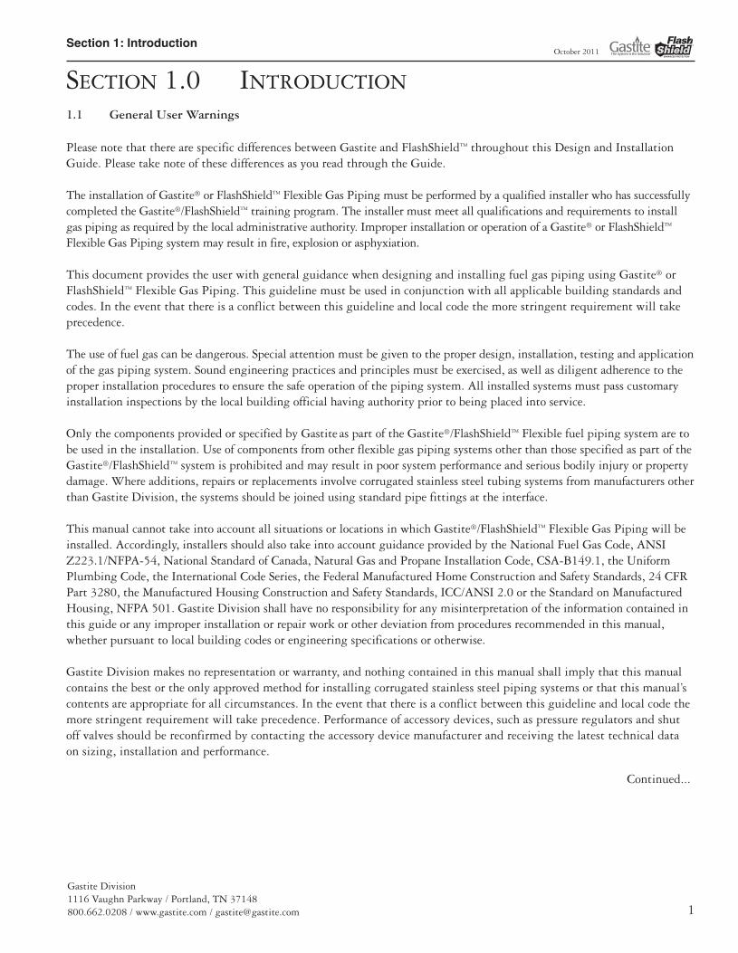
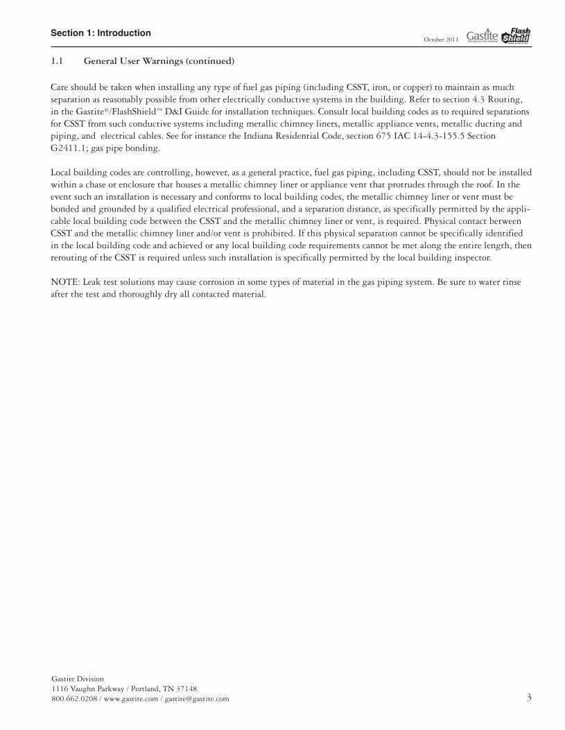
Step 1Cut-to-Length (Fig. 4-2)
Cut tubing to the desired length leaving approximately one inch for fitting attachment.Cut should be centered between two corrugations. Use light roller pressure with extra ro-tations in one direction to leave tubing round and free of burrs. Note: To ensure a qualityflare, all cuts should be made on a straight section of tubing.
Step 2 Strip Jacket (Fig. 4-3)
Using a utility knife, strip jacket back to the valley of the second corrugation. Do not cut the jacket in such a way that the sealing surface of the tubing is scored. The shortpiece of jacket can easily be removed by placing the utility knife blade under the jacket topeel the jacket off.Caution: Tube ends are sharp, use care when handling.
Step 3 Install Nut and Bushings (Fig. 4-4)
Thread fitting body into appliance. Slide nut over tubing. Separate bushings and position,as shown in Figure 4-6, into the valley of the first corrugation leaving one corrugation ex-posed between the end of the bushing and tubing.
At this point, the bushings will begin to capture the jacket for a contaminant resistant seal(Fig. 4-5).
NOTE:
• It is important to know that the jacket locking feature of the Jacket-Lock fitting is not re-quired to produce a gas-tight seal between the fitting and the tubing (Fig. 4-6).
• Pipe dope or sealant must not be used inside the fitting prior to assembly.
Fig. 4-2
Fig. 4-3
Fig. 4-4
Fig. 4-5
Fig. 4-6
Jacket Locking Feature
13133_Gastite_D+I_Guide_Winter2011_5_SEC4 5/30/12 9:39 AM Page 50
Section 4: Installation Practices
Gastite Division1116 Vaughn Parkway / Portland, TN 37148800.662.0208 / www.gastite.com / [email protected] 51
October 2011
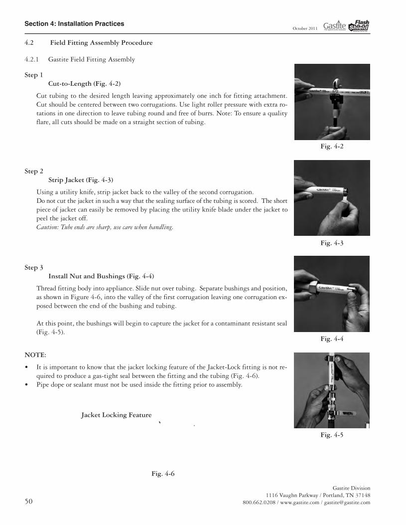
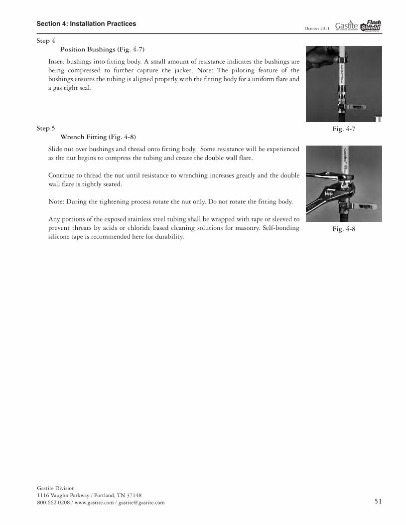
Step 4 Position Bushings (Fig. 4-7)
Insert bushings into fitting body. A small amount of resistance indicates the bushings arebeing compressed to further capture the jacket. Note: The piloting feature of thebushings ensures the tubing is aligned properly with the fitting body for a uniform flare anda gas tight seal.
Step 5 Wrench Fitting (Fig. 4-8)
Slide nut over bushings and thread onto fitting body. Some resistance will be experiencedas the nut begins to compress the tubing and create the double wall flare.
Continue to thread the nut until resistance to wrenching increases greatly and the doublewall flare is tightly seated.
Note: During the tightening process rotate the nut only. Do not rotate the fitting body.
Any portions of the exposed stainless steel tubing shall be wrapped with tape or sleeved toprevent threats by acids or chloride based cleaning solutions for masonry. Self-bondingsilicone tape is recommended here for durability.
Fig. 4-7
Fig. 4-8
13133_Gastite_D+I_Guide_Winter2011_5_SEC4 5/30/12 9:39 AM Page 51

Section 4: Installation Practices
Gastite Division1116 Vaughn Parkway / Portland, TN 37148
800.662.0208 / www.gastite.com / [email protected]
October 2011
4.2.2 FlashShield Field Fitting Assembly
Step 1Cut-to-Length (Fig. 4-9)
Cut tubing to the desired length leaving approximately one inch for fitting attachment.Cut should be centered between two corrugations. Use light roller pressure with extra ro-tations in one direction to leave tubing round and free of burrs. Note: To ensure a qual-ity flare, all cuts should be made on a straight section of tubing.
Step 2 Strip Jacket (Fig. 4-10, Fig. 4-11)
Using a utility knife, strip jacket back to the valley of the second corrugation. Do not cut the jacket in such a way that the sealing surface of the tubing is scored. Theshort piece of jacket can easily be removed by placing the utility knife blade under thejacket to peel the jacket off.Caution: Tube ends are sharp, use care when handling.
Step 3 Install Nut and Bushings (Fig. 4-12)
Thread fitting body into appliance. Slide nut over tubing. Separate bushings and position,as shown in Figure 4-13, into the valley of the first corrugation leaving one corrugationexposed between the end of the bushing and tubing.
NOTE:
• Foil biting feature must be utilized with FlashShield.• Pipe dope or sealant must not be used inside the fitting prior to assembly.
Fig. 4-13
Foil Biting Feature
Fig. 4-9
Fig. 4-10
Fig. 4-11
Fig. 4-12
13133_Gastite_D+I_Guide_Winter2011_5_SEC4 5/30/12 9:39 AM Page 52
Section 4: Installation Practices
Gastite Division1116 Vaughn Parkway / Portland, TN 37148800.662.0208 / www.gastite.com / [email protected] 53
October 2011
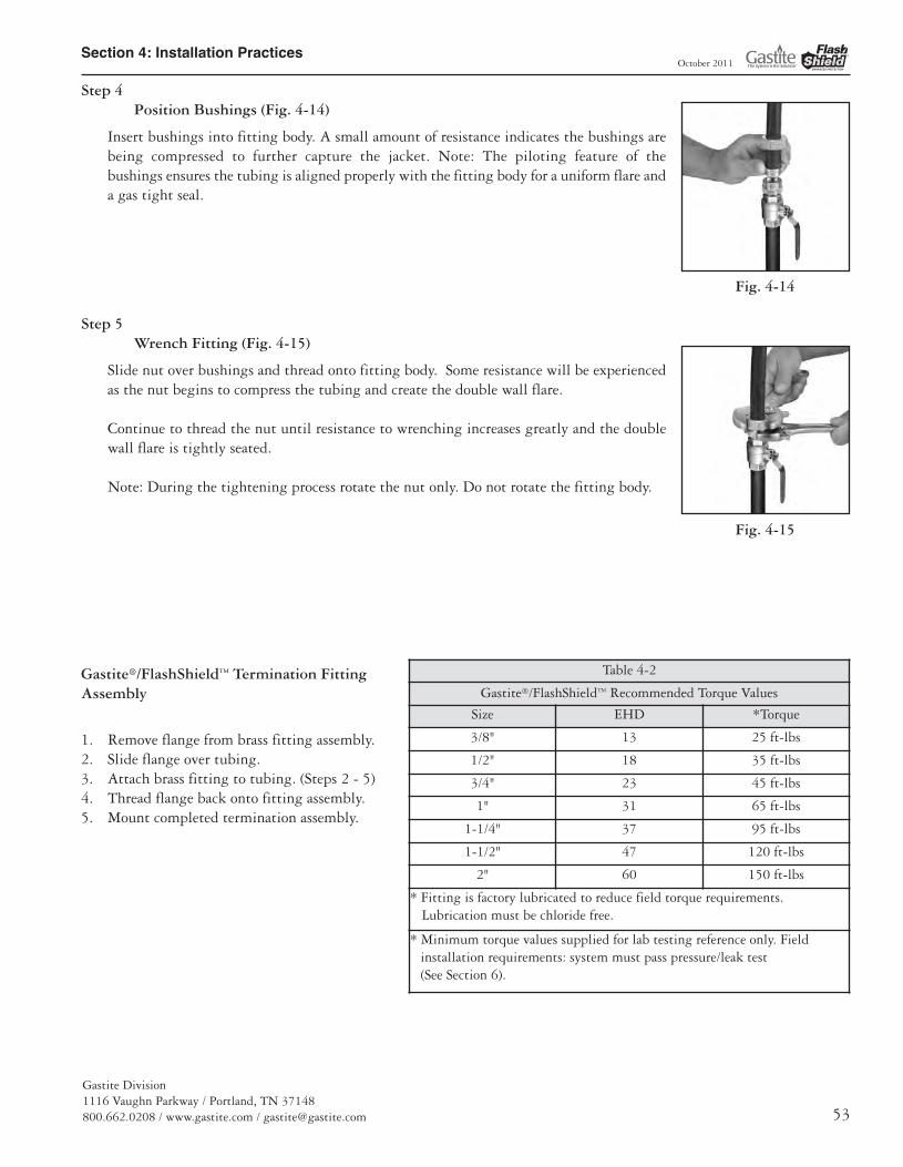
Step 4 Position Bushings (Fig. 4-14)
Insert bushings into fitting body. A small amount of resistance indicates the bushings arebeing compressed to further capture the jacket. Note: The piloting feature of thebushings ensures the tubing is aligned properly with the fitting body for a uniform flare anda gas tight seal.
Step 5 Wrench Fitting (Fig. 4-15)
Slide nut over bushings and thread onto fitting body. Some resistance will be experiencedas the nut begins to compress the tubing and create the double wall flare.
Continue to thread the nut until resistance to wrenching increases greatly and the doublewall flare is tightly seated.
Note: During the tightening process rotate the nut only. Do not rotate the fitting body.
Gastite®/FlashShield™ Termination FittingAssembly
1. Remove flange from brass fitting assembly.2. Slide flange over tubing.3. Attach brass fitting to tubing. (Steps 2 - 5)4. Thread flange back onto fitting assembly.5. Mount completed termination assembly.
Fig. 4-14
Fig. 4-15
Table 4-2
Gastite®/FlashShield™ Recommended Torque Values
Size EHD *Torque
3/8" 13 25 ft-lbs
1/2" 18 35 ft-lbs
3/4" 23 45 ft-lbs
1" 31 65 ft-lbs
1-1/4" 37 95 ft-lbs
1-1/2" 47 120 ft-lbs
2" 60 150 ft-lbs
* Fitting is factory lubricated to reduce field torque requirements.Lubrication must be chloride free.
* Minimum torque values supplied for lab testing reference only. Fieldinstallation requirements: system must pass pressure/leak test(See Section 6).
13133_Gastite_D+I_Guide_Winter2011_5_SEC4 5/30/12 9:39 AM Page 53
Section 4: Installation Practices
Gastite Division1116 Vaughn Parkway / Portland, TN 37148
800.662.0208 / www.gastite.com / [email protected]
October 2011
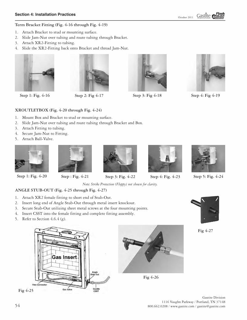
Term Bracket Fitting (Fig. 4-16 through Fig. 4-19)
1. Attach Bracket to stud or mounting surface.2. Slide Jam-Nut over tubing and route tubing through Bracket.3. Attach XR2-Fitting to tubing.4. Slide the XR2-Fitting back onto Bracket and thread Jam-Nut.
XROUTLETBOX (Fig. 4-20 through Fig. 4-24)
1. Mount Box and Bracket to stud or mounting surface.2. Slide Jam-Nut over tubing and route tubing through Bracket and Box.3. Attach Fitting to tubing.4. Secure Jam-Nut to Fitting.5. Attach Ball-Valve.
ANGLE STUB-OUT (Fig. 4-25 through Fig. 4-27)
1. Attach XR2 female fitting to short end of Stub-Out.2. Insert long end of Angle Stub-Out through metal insert knockout.3. Secure Stub-Out utilizing sheet metal screws at the four mounting points. 4. Insert CSST into the female fitting and complete fitting assembly.5. Refer to Section 4.6.4 (g).
Step 1: Fig. 4-16 Step 4: Fig 4-19Step 3: Fig 4-18Step 2: Fig 4-17
Step 1: Fig. 4-20 Step : Fig. 4-21 Step 3: Fig. 4-22 Step 4: Fig. 4-23 Step 5: Fig. 4-24
Note: Strike Protection (Floppy) not shown for clarity.
Fig 4-27
Fig 4-25
Fig 4-26
13133_Gastite_D+I_Guide_Winter2011_5_SEC4 5/30/12 9:39 AM Page 54
Section 4: Installation Practices
Gastite Division1116 Vaughn Parkway / Portland, TN 37148800.662.0208 / www.gastite.com / [email protected] 55
October 2011
4.3 Routing
4.3.1 Vertical Runs
Vertical runs are the preferred run method. Tubing runs should be relatively plumb and free to move within the wall cavity without any physical support between the floors. For support requirements refer to Section 4.1.f. Where any run isgreater than two stories or 20-ft, additional support (appropriate to the weight of the tubing) must be provided at the pointof penetration through the floor.
Care should be taken when installing vertical runs to maintain as much separation as reasonably possible from otherelectrically conductive systems in the building.
There is no requirement to maintain separation from other electrically conductive systems when routing FlashShield™
4.3.2 Horizontal Runs
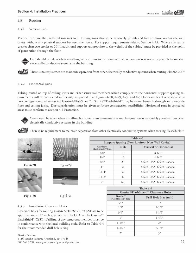
Tubing routed on top of ceiling joists and other structural members which comply with the horizontal support spacing re-quirements will be considered sufficiently supported . See Figures 4-28, 4-29, 4-30 and 4-31 for examples of acceptable sup-port configurations when routing Gastite®/FlashShield™. Gastite®/FlashShield™ may be routed beneath, through and alongsidefloor and ceiling joists. Due consideration must be given to future construction possibilities. Horizontal runs in concealedareas must conform to Section 4.4 Protection.
Care should be taken when installing horizontal runs to maintain as much separation as reasonably possible from otherelectrically conductive systems in the building.
There is no requirement to maintain separation from other electrically conductive systems when routing FlashShield™.
4.3.3 Installation Clearance Holes
Clearance holes for routing Gastite®/FlashShield™ CSST are to beapproximately 1/2 inch greater than the O.D. of the Gastite®/FlashShield™ CSST. Drilling of any structural member must bein conformance with the local building code. Refer to Table 4-4for the recommended drill hole sizing.
Fig 4-28
Fig 4-31Fig 4-30
Fig 4-29
Gastite®/FlashShield™ Size Drill Hole Size (min)
3/8" 1"1/2" 1-1/4"
3/4" 1-1/2"
1" 1-3/4"
1-1/4" 2"
1-1/2" 2-1/4"
2" 3"
Gastite®/FlashShield™ Size
EHD Vertical or Horizontal
3/8" 13 4 Feet1/2" 18 6 Feet
3/4" 23 8 feet (USA) 6 feet (Canada)
1" 31 8 feet (USA) 6 feet (Canada)
1-1/4" 37 8 feet (USA) 6 feet (Canada)
1-1/2" 47 8 feet (USA) 6 feet (Canada)
2" 60 8 feet (USA) 6 feet (Canada)
Support Spacing (Non-Rooftop, Non-Wall Cavity)Table 4-3
Gastite®/FlashShield™ Clearance HolesTable 4-4
13133_Gastite_D+I_Guide_Winter2011_5_SEC4 5/30/12 9:39 AM Page 55

Section 4: Installation Practices
Gastite Division1116 Vaughn Parkway / Portland, TN 37148
800.662.0208 / www.gastite.com / [email protected]
October 2011
4.3.4 Concealed Fittings
The Gastite®/FlashShield™ Mechanical Fittings have been tested and listed per the requirements of ANSI LC-1 for concealeduse. The fitting may be used for concealed attachment including, but not limited to: appliance valves, branch runs using teefittings, length splices and stub-outs manufactured from approved fuel gas piping materials.
These guidelines address some of the most common situations where concealing the fittings is the only practical alternative.These guidelines cannot address all applications of concealed fittings, but instead, provide typical instructions to demonstratethe principles that apply to fittings listed for installation in concealed locations. (Reference National Fuel Gas Code, NFPA54, Concealed Piping in Buildings).
a) New Installations (Fig. 4-32) – When multiple gasoutlets are supplied from a single run of Gastite®/FlashShield™ CSST, each downstream outlet branchcan be connected to the main run using a tee-typefitting which can be located in a concealed location.
b) Fireplace key valves (Fig. 4-33) – Gastite®/FlashShield™ CSST connections to fireplace keyvalves can be located in a concealed location whenaccessibility is not readily provided.
c) Stub-outs (Fig. 4-34) – Gastite®/FlashShield™CSSTconnections to stub-outs fabricated from approvedfuel gas piping materials.
d) Exclusion – Manifold stations for dual pressure sys-tems which include the multi-port manifold, shut-off valve and pressure regulator shall not be installed in concealed loca-tions regardless of the qualifications of the tubing.
4.3.5 Modifications to Existing Systems
a) New Ceilings in Unfinished Rooms/Basements – Gastite®/FlashShield™ CSST fittings originally installed in accessible ceil-ing locations can be concealed in the event a ceiling is installed at a later date.
b) Extensions to Existing Tubing Runs – Concealed tubing can be modified to permit an extension to another appliance lo-cation provided there is sufficient capacity to supply both appliances at the same time. If an accessible location for themodification is not available, the existing tubing run can be modified with a tee fitting that will result in a concealed fit-ting behind the wallboard.
c) When modifications lead to concealed tubing, strike protection may be required. Refer to section 4.4.
Fig 4-33 Fig 4-34
Fig 4-32
Note: Strike Protection (Floppy) not shown for clarity.
13133_Gastite_D+I_Guide_Winter2011_5_SEC4 5/30/12 9:39 AM Page 56

Section 4: Installation Practices
Gastite Division1116 Vaughn Parkway / Portland, TN 37148800.662.0208 / www.gastite.com / [email protected] 57
October 2011
4.3.6 Outdoor
Gastite®/FlashShield™ Flexible Gas Tubing has passed all requirements of ANSI LC1, which include testing for suitability forexposure of CSST piping systems to outdoor environments.
a) Outdoors – When installed outdoors, the external jacketing shall remain intact as much as practical for the given instal-lation. Any portions of the exposed stainless steel tubing shall be wrapped with tape or sleeved to prevent later threats byacid or chloride based cleaning solutions for masonry. Self-bonding silicone tape is recommended here for durability.
b) Along side a structure – When installed along the outside of a structure (between the ground and a height of 6 ft.) in anexposed condition, the Gastite®/FlashShield™ CSST shall be protected from mechanical damage inside a conduit or chase.A conduit or chase is not required if the tubing is installed in a location that will not subject the Gastite®/FlashShield™
CSST to mechanical damage.
4.3.7 Fire Rated Construction
The Gastite® plastic jacket on the steel tubing has a maximum ASTM E84 rating of 15 for flame spread, and 30 for smoke den-sity. These values meet most typical requirements for building construction. Therefore, the jacket should remain intact whenpassing through typical building constructions such as plenums, floor and ceiling joists, rim joists, walls or other fire rated re-sistance construction limited to materials of ASTM E84 ratings of 25 flame and 50 smoke, or lower.
The FlashShield jacket has a maximum ASTM E84 rating of 5 for flame spread and 30 for smoke density. These values meet mosttypical requirements for building construction. Therefore, the jacket should remain intact when passing though typical build-ing construction such as plenums, floor and ceiling joists, rim joists, walls, and other fire rated resistance construction limited tomaterials of ASTM E84 ratings of 25 flame and 50 smoke or lower.
A plenum is defined as an enclosed portion of the building structure that is designed to allow air movement, and thereby serveas part of an air distribution system. (See definition of Plenum, Section 8.0.) No gas tubing may be run within ductwork.
For tubing passing through a UL classified fire rated construction, UL Classified Systems for “Through-Penetration Firestop Sys-tems (XHEZ)” may be found in UL Fire Resistance Volume 2. In instances that UL specifications for fire rated construction con-flict with the current Gastite Design and Installation Guide, UL takes precedence.
UL Through-Penetration Firestop System information is available on the Gastite® Web site at www.gastite.com.
4.3.8 Routing Through Masonry Material
“Masonry material” includes but is not limited to brick, concrete, mortar, and stucco. The term “through masonry construction”refers to any enclosed/concealed construction spaces where CSST is routed in close proximity to masonry but does not apply toexposed CSST mounted to a set masonry surface.
When it is necessary to install Gastite®/FlashShield through masonry materials the tubing shall be routed through a conduit thatis a ½" larger in diameter (to ease routing) than the OD of the CSST and appropriate for the application. The sleeve must maintain a continuous watertight barrier between the masonry material and the CSST, up to or past the edge of the masonry hole.
Masonry encasement refers to any enclosed/concealed construction within “masonry material” that produces distributed loads. Formasonry encasement see Underground Installations (section 4.9).
4.3.9 Installation Within a Chimney Chase
Gastite tubing shall not be installed within a chase and/or enclosure that includes a metallic appliance vent and/ormetallic chimney liner that protrudes through and/or past the roof unless:
• Permitted by local building code,
• An express separation distance as required by local code can be achieved along the entire length,
• The vent and/or liner is directly bonded to the grounding electrode system, AND
• There is no physical contact between the metallic vent and/or liner and the Gastite tubing along the entirelength of the vent.
FlashShield™ CSST may be routed within a chimney chase, the restrictions of section 4.3.9 (Installation within achase) do not apply.
13133_Gastite_D+I_Guide_Winter2011_5_SEC4 5/30/12 9:39 AM Page 57
Section 4: Installation Practices
Gastite Division1116 Vaughn Parkway / Portland, TN 37148
800.662.0208 / www.gastite.com / [email protected]
October 2011
4.4 Strike Protection
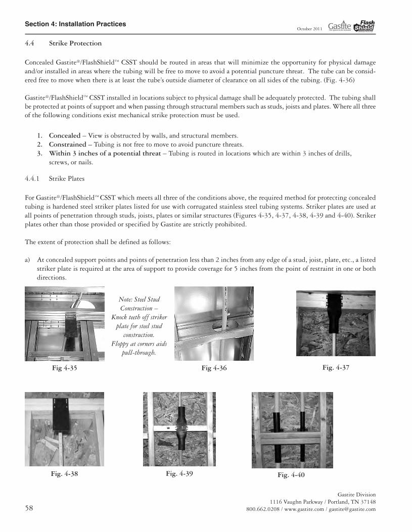
Concealed Gastite®/FlashShield™ CSST should be routed in areas that will minimize the opportunity for physical damageand/or installed in areas where the tubing will be free to move to avoid a potential puncture threat. The tube can be consid-ered free to move when there is at least the tube’s outside diameter of clearance on all sides of the tubing. (Fig. 4-36)
Gastite®/FlashShield™ CSST installed in locations subject to physical damage shall be adequately protected. The tubing shallbe protected at points of support and when passing through structural members such as studs, joists and plates. Where all threeof the following conditions exist mechanical strike protection must be used.
1. Concealed – View is obstructed by walls, and structural members.2. Constrained – Tubing is not free to move to avoid puncture threats.3. Within 3 inches of a potential threat – Tubing is routed in locations which are within 3 inches of drills,
screws, or nails.
4.4.1 Strike Plates
For Gastite®/FlashShield™ CSST which meets all three of the conditions above, the required method for protecting concealedtubing is hardened steel striker plates listed for use with corrugated stainless steel tubing systems. Striker plates are used atall points of penetration through studs, joists, plates or similar structures (Figures 4-35, 4-37, 4-38, 4-39 and 4-40). Strikerplates other than those provided or specified by Gastite are strictly prohibited.
The extent of protection shall be defined as follows:
a) At concealed support points and points of penetration less than 2 inches from any edge of a stud, joist, plate, etc., a listedstriker plate is required at the area of support to provide coverage for 5 inches from the point of restraint in one or bothdirections.
Fig. 4-37
Fig. 4-39Fig. 4-38 Fig. 4-40
Fig 4-35 Fig 4-36
Note: Steel Stud Construction –
Knock teeth off strikerplate for steel stud
construction.Floppy at corners aids
pull-through.
13133_Gastite_D+I_Guide_Winter2011_5_SEC4 5/30/12 9:39 AM Page 58

Section 4: Installation Practices
Gastite Division1116 Vaughn Parkway / Portland, TN 37148800.662.0208 / www.gastite.com / [email protected] 59
October 2011
b) At concealed support points and points of penetration 2 to 3 inches from any edge of a stud, joist plate, etc., listed 1/4striker plates are required to provide protection throughout the area of penetration (Fig. 4-41 and 4-42).
c) When multiple runs are located between the same two studs such as manifold runs ormeter bank runs, a 6" x 17" panel type strikerplate may be used as an alternate to individualstriker plates for each tubing run (Fig. 4-44).
d) When installed inside insulated exterior walls, tubing shall berouted between the face of the insulation and the interior wallsurface (Fig. 4-45). If rigid insulation is used, enough spacemust be provided for movement of the tubing (see Section 4.4)or heavy wall conduit must run over the length of the re-strained area.
e) At points of penetration greater than 3 inches from any edge ofstud, joist, plate, etc., no protection is required.
f) Tubing routed horizontally through structural members shall be protected from puncture threats with the appropriateshielding material (Figure 4-41 and 4-42). At penetration points, listed plates of the appropriate size shall be utilized.Tubing between constraints that are less than 24 inches apart and meeting the criteria requiring full striker plates, shallbe additionally protected by Steel Conduit (Fig. 4-43).
g) Gastite®/FlashShield™ CSST greater than 1" nominal diameter installed within a concealed hollow wall cavity of 2"x4" construction shall be protected along the entire concealed run length with Steel Conduit (see Section 4.4.2).
h) The width of installed striker plates shall be at least 1.5 times the outside diameter of the Gastite®/FlashShield™ CSST.
Fig. 4-41
Fig. 4-44Fig. 4-43
Fig. 4-45
Fig. 4-42
13133_Gastite_D+I_Guide_Winter2011_5_SEC4 5/30/12 9:39 AM Page 59

Section 4: Installation Practices
Gastite Division1116 Vaughn Parkway / Portland, TN 37148
800.662.0208 / www.gastite.com / [email protected]
October 2011
4.4.2 Steel Conduit
At termination points not covered by the ANSI standard,floppy steel conduit (heavy wall) shall be installed as addi-tional protection (Fig. 4-46 and 4-47). Gastite®/FlashShield™
requires a minimum of six inches of conduit and supplies precut conduit in one foot lengths. Floppy Steel conduitshould not be used in place of hardened steel striker plateswhen passing through structural members.
4.5 Meter
The gas piping for the meter stub-out is usually subject to local requirements such as size, location, and material type. It isalways important to confirm local code and utility requirements. Gastite®/FlashShield recommends the use of 1/2" CSST orgreater as the minimum trunk line size. Size 3/8" should not be used for trunk lines. This will allow for the addition of fu-ture gas appliances and minimize the opportunity for whistling.
a) Unsupported Meters – Meters that depend on theservice supply line and/or the house piping for support shall not be directly connected to theGastite®/FlashShield™ CSST. As shown in the Figures 4-48 and 4-49, a rigid connection point iscreated using a Gastite®/FlashShield™ terminationfitting, Gastite® designed stub-out or rigid pipecomponents.
b) Self-Supported Meters – Meters that are independ-ently supported with a bracket can be directly con-nected to the Gastite®/FlashShield™ CSST as shown inFigure 4-51. If practical, direct Gastite®/FlashShield™
CSST connections shall include a 3 to 6 inch loop oftubing (as shown) to accommodate differential settlingand meter movement. No mechanical protection ofthe tubing is required for outdoor meter connections;however, ensure that the local utility supports thispractice as some utilities have regulations specifyingmeter attachments. Ensure that any exposed sections(jacket removed) of the stainless tubing at the fittingare wrapped with tape. This is especially important with masonry constructions.
c) Electrical bonding connections made at the gas meter must comply with section 4.10 of this guide.
Fig. 4-47
Fig. 4-46
Fig. 4-48 Fig. 4-49
Fig. 4-50
13133_Gastite_D+I_Guide_Winter2011_5_SEC4 5/30/12 9:39 AM Page 60

Section 4: Installation Practices
Gastite Division1116 Vaughn Parkway / Portland, TN 37148800.662.0208 / www.gastite.com / [email protected] 61
October 2011
4.6 Appliance
4.6.1 Moveable Appliance
a) For use with movable appliances, Gastite®/FlashShield™ must be rigidly terminated before the appliance connection. Thisfixed connection point allows for the attachment of flexible appliance connectors, drip legs (if required), and shut offvalves to moveable appliances such as dryers and ranges (Figures 4-51 and 4-52).
b) The Appliance Stub-Out is mounted to a stud face (Fig. 4-53) and provides a fixed point to which a Gastite®/FlashShield™
mechanical fitting may be attached. The design of this stub-out ensures that the flexible tubing is routed away from anypoints of constraint that may subject the tubing to potential puncture threats.
c) The Straight Stub provides a fixed point for the Gastite®/FlashShield™ mechanical fitting and a stable platform for serv-ice meter connections. The Straight Stub may be mounted to the face of a stud (Fig. 4-54) or mounted to an optionalStub Bracket with supplied self-drilling metal screws (Fig. 4-55). The optional bracket is designed to span typical studconstruction. The compact design of the straight stub allows for multiple stub-outs within the stud cavity.
The Straight Stub may also be used to pass through joist and wall constructions (Fig. 4-56). It is important to follow allrequirements for sleeving when passing through masonry construction.
Fig. 4-52Fig. 4-51
Fig. 4-53 Fig. 4-54 Fig. 4-55 Fig. 4-56
13133_Gastite_D+I_Guide_Winter2011_5_SEC4 5/30/12 9:39 AM Page 61

Section 4: Installation Practices
Gastite Division1116 Vaughn Parkway / Portland, TN 37148
800.662.0208 / www.gastite.com / [email protected]
October 2011
4.6.2 Direct Connection – Non-Moveable Appliances
Gastite®/FlashShield™ CSST may be connected directly to non-mov-able appliances such as water heaters, furnaces, boilers and islandcook-tops (Figures 4-57) without the installation of a terminationoutlet or flexible appliance connector. All local codes requiring driplegs and shut-off valves must be observed. Drip legs and shut-offvalves must be securely mounted.
a) When appliances such as water heaters, furnaces or fireplaces havemetallic vents which extend beyond or protrude through the roofphysical contact between the Gastite® CSST and the appliance
cabinet or vent is prohibited. Gastite recommends that allcontinuous metallic systems be bonded and grounded.
Physical contact with appliance cabinets that have metallicvents which extend beyond or protrude through the roof isacceptable.
4.6.3 Gas Convenience Outlet
a) Barbecue Grills – Movable grills shall be connected using an approved outdoor appliance connector which shall be attachedto the CSST system either at a termination fitting or a quick disconnect device as shown in the figure(Fig. 4-58).
b) Permanently mounted grills located on decks (Fig. 4-59) shall be connected to the CSST system as shown in the figureand in accordance with the manufacturer’s instructions. The outdoor portion of the CSST run shall be supported againstthe side of any of the inside deck joists.
Fig. 4-57
Fig. 4-59Fig. 4-58
13133_Gastite_D+I_Guide_Winter2011_5_SEC4 5/30/12 9:39 AM Page 62
Section 4: Installation Practices
Gastite Division1116 Vaughn Parkway / Portland, TN 37148800.662.0208 / www.gastite.com / [email protected] 63
October 2011
4.6.4 Special Applications
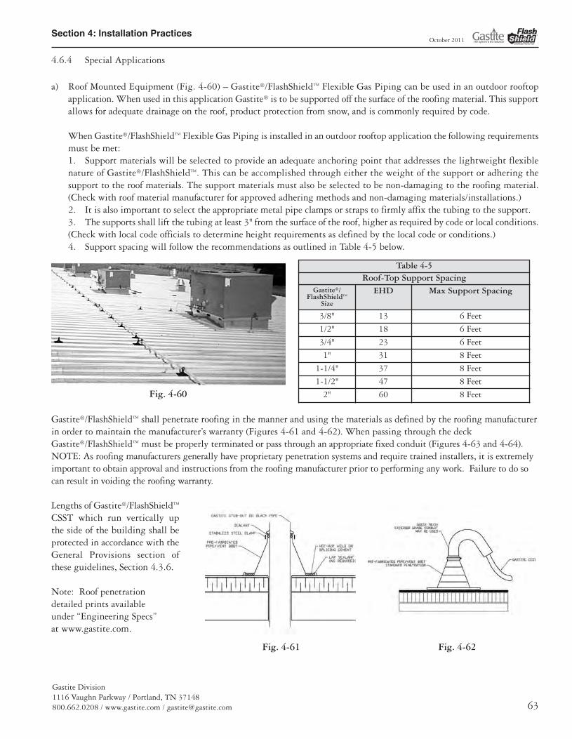
a) Roof Mounted Equipment (Fig. 4-60) – Gastite®/FlashShield™ Flexible Gas Piping can be used in an outdoor rooftopapplication. When used in this application Gastite® is to be supported off the surface of the roofing material. This supportallows for adequate drainage on the roof, product protection from snow, and is commonly required by code.
When Gastite®/FlashShield™ Flexible Gas Piping is installed in an outdoor rooftop application the following requirementsmust be met:1. Support materials will be selected to provide an adequate anchoring point that addresses the lightweight flexiblenature of Gastite®/FlashShield™. This can be accomplished through either the weight of the support or adhering thesupport to the roof materials. The support materials must also be selected to be non-damaging to the roofing material.(Check with roof material manufacturer for approved adhering methods and non-damaging materials/installations.)2. It is also important to select the appropriate metal pipe clamps or straps to firmly affix the tubing to the support.3. The supports shall lift the tubing at least 3" from the surface of the roof, higher as required by code or local conditions.(Check with local code officials to determine height requirements as defined by the local code or conditions.)4. Support spacing will follow the recommendations as outlined in Table 4-5 below.
Gastite®/FlashShield™ shall penetrate roofing in the manner and using the materials as defined by the roofing manufacturerin order to maintain the manufacturer’s warranty (Figures 4-61 and 4-62). When passing through the deckGastite®/FlashShield™ must be properly terminated or pass through an appropriate fixed conduit (Figures 4-63 and 4-64).NOTE: As roofing manufacturers generally have proprietary penetration systems and require trained installers, it is extremelyimportant to obtain approval and instructions from the roofing manufacturer prior to performing any work. Failure to do socan result in voiding the roofing warranty.
Lengths of Gastite®/FlashShield™
CSST which run vertically up the side of the building shall beprotected in accordance with theGeneral Provisions section ofthese guidelines, Section 4.3.6.
Note: Roof penetration detailed prints available under “Engineering Specs” at www.gastite.com.
Gastite®/FlashShield™
Size
EHD Max Support Spacing
3/8" 13 6 Feet
1/2" 18 6 Feet
3/4" 23 6 Feet
1" 31 8 Feet
1-1/4" 37 8 Feet
1-1/2" 47 8 Feet
2" 60 8 FeetFig. 4-60
Fig. 4-61 Fig. 4-62
Roof-Top Support SpacingTable 4-5
13133_Gastite_D+I_Guide_Winter2011_5_SEC4 5/30/12 9:39 AM Page 63
Section 4: Installation Practices
Gastite Division1116 Vaughn Parkway / Portland, TN 37148
800.662.0208 / www.gastite.com / [email protected]
October 2011
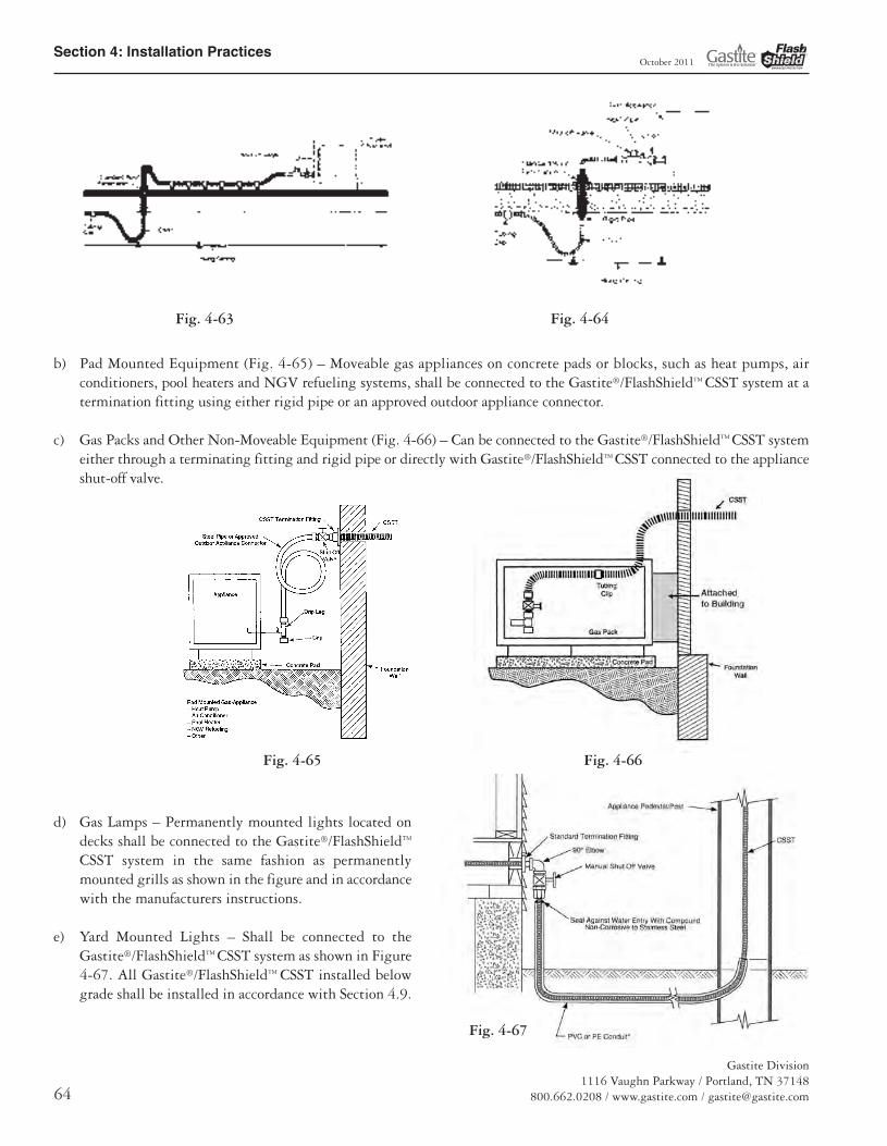
b) Pad Mounted Equipment (Fig. 4-65) – Moveable gas appliances on concrete pads or blocks, such as heat pumps, airconditioners, pool heaters and NGV refueling systems, shall be connected to the Gastite®/FlashShield™ CSST system at atermination fitting using either rigid pipe or an approved outdoor appliance connector.
c) Gas Packs and Other Non-Moveable Equipment (Fig. 4-66) – Can be connected to the Gastite®/FlashShield™ CSST systemeither through a terminating fitting and rigid pipe or directly with Gastite®/FlashShield™ CSST connected to the applianceshut-off valve.
d) Gas Lamps – Permanently mounted lights located ondecks shall be connected to the Gastite®/FlashShield™
CSST system in the same fashion as permanentlymounted grills as shown in the figure and in accordancewith the manufacturers instructions.
e) Yard Mounted Lights – Shall be connected to theGastite®/FlashShield™ CSST system as shown in Figure4-67. All Gastite®/FlashShield™ CSST installed belowgrade shall be installed in accordance with Section 4.9.
Fig. 4-63 Fig. 4-64
Fig. 4-65 Fig. 4-66
Fig. 4-67
13133_Gastite_D+I_Guide_Winter2011_5_SEC4 5/30/12 9:39 AM Page 64

Section 4: Installation Practices
Gastite Division1116 Vaughn Parkway / Portland, TN 37148800.662.0208 / www.gastite.com / [email protected] 65
October 2011
f) Infrared Heaters (Fig. 4-68) - Infraredheaters that are solidly mounted toceilings and walls of structures may beconnected to the Gastite®/FlashShield™
CSST system as shown in the figuresbelow and in accordance with the man-ufacturers instructions. High Densityinfrared heaters generally fall into thiscategory. Gastite®/FlashShield™ CSSTshould be mounted to a fixed point andnot on the end involved with the typicalexpansion and contraction associatedwith these heaters.
Infrared heaters that are mounted toallow movement of the heater must usean appropriate appliance/flex connectorbetween the heater and the properly terminated Gastite®/FlashShield™. Low Density heaters, tube heaters and heaters hungfrom chains fall into this category.
Heaters and installations must comply with ANSI Z83.6, “Standard for gas fired infrared heaters.”
g) Gas Fireplace – Gastite®/FlashShield™ Flexible Gas Tubing may be used to deliver gas directly to the control valve of agas fireplace (Fig. 4-69). Gastite®/FlashShield™ Flexible Gas Piping may also be used to deliver gas directly to the insertof a gas fireplace in decorative and heat generating fireplaces (Fig. 4-70). Per code valves shall be rigidly mounted.
CSST and Gastite®/FlashShield™ brass fittings should not be used inside the firebox for log lighters/gas wands or in anyfirebox where wood logs will be burned due to the potential for physical harm to the tubing (Fig. 4-71).
Fig. 4-68
Fig. 4-69 Fig. 4-70 Fig. 4-71
13133_Gastite_D+I_Guide_Winter2011_5_SEC4 5/30/12 9:39 AM Page 65

Section 4: Installation Practices
Gastite Division1116 Vaughn Parkway / Portland, TN 37148
800.662.0208 / www.gastite.com / [email protected]
October 2011
The Gastite® Angle Stub is designed to create a secure mountingpoint or stub-out for the transition from Gastite®/FlashShield™
CSST to log-lighters, gas logs, or firebox insert’s controls. Refer toSection 4.2 for Angle Stub Installation.
The Gastite® Angle Stub shall not be connected in such a way thatthe log-lighter, gas log, or other components angle out of the fire-place. To correct for the insertion angle into the firebox, metalshims such as fender washers can be used. (See the proper and improper installation Fig. 4-72)
Gastite®/FlashShield™ Mechanical Fittings are approved to be concealed and can be connected directly to a valve controllinggas flow to a fireplace appliance. The Gastite®/FlashShield™ CSST and valve connection can be installed behind the wall,beneath the floor, hearth, or behind the brickwork of the fireplace (Fig. 4-75).
Where it is necessary to install Gastite®/FlashShield™ through masonry materials in fireplace construction, the plastic jacketshall remain intact and the tubing should be routed through sleeving that is appropriate for the application. Sleeving is notrequired through ceramic liners in decorative fireplaces and heat generating fireplaces.
Gastite®/FlashShield™ may not be run above the flue within a masonry chimney.
Where it is necessary to install Gastite®/FlashShield™ through sheet metal enclosures (such as fireplaces) the tubing should berouted or supported to prevent physical contact with the enclosure. If direct contact cannot be avoided a rubber grommetmay be used to prevent physical contact with the enclosure. Otherwise a Gastite® angle stub or rigid pipe componentsmust be used.
In certain configurations corrugated tubing or flexible appliance connectors feeding a fireplace or gas log set can whistle due togas flow velocity. Acoustics can usually be avoided by restricting Gastite®/FlashShield™ CSST sizes to the maximum capacityas shown in Table 4-6 below.
Proper Angle Stub In-stallation
Improper Angle Stub In-stallation
Fig. 4-75
Note: Strike Protection(Floppy) not shown for clarity.
Fig. 4-74Fig. 4-73
Gastite®/FlashShield™ Size EHD BTUH
1/2" 18 45,000
3/4" 23 80,000
1" 31 125,000
Fig. 4-72
No Physical Contact
Fireplace SizingTable 4-6
13133_Gastite_D+I_Guide_Winter2011_5_SEC4 5/30/12 9:39 AM Page 66

Section 4: Installation Practices
Gastite Division1116 Vaughn Parkway / Portland, TN 37148800.662.0208 / www.gastite.com / [email protected] 67
October 2011
4.7 Manifold
Manifolds are installed where multiple runs are made from a common location in a parallel arrangement. The manifold maybe manufactured from a one-piece malleable iron or brass casting (Fig. 4-76), a welded fabrication of steel sub-components oran assembly of approved, malleable iron tees and short nipples (Fig. 4-77). Manifolds must be rigidly installed. This can beachieved through the use of a mounted manifold bracket or by rigidly piping into a non-movable gas-piping component.
Depending on the location and available space, different mounting arrangements are permitted. A manifold may be mountedin any orientation on the surface of an interior wall, between open floor joists, in attic spaces, crawl spaces, within a partitionwall, or inside an enclosure. A manifold assembly without a regulator can be concealed.
The Gastite®/FlashShield™ CSST Capacity Tables include losses for four 90° bends and two end fittings. Tubing runs with alarger number of bends and/or fittings shall be increased by an equivalent length of tubing to the following equation: L=1.3nwhere L is additional length of tubing and n is the number of additional fittings and/or bends. Each port of a manifold canbe taken as an additional fitting. For example: the tube running from the last port of a 3-port manifold should have 3.9 feet(3 ports/fittings x 1.3) added to the run length for the purpose of sizing. This method is applicable for all manifolds whoseports are equal or greater in size than the pipe connected to the corresponding port.
The installation of manifold assemblies using a pounds-to-inches regulator must be in accordance with all local codes, and thefollowing guidelines:
a) A manifold assembly directly integrating a pounds-to-inches regulator shall be installed in an accessible location so thatthe regulator can be inspected, maintained and serviced if repair or replacement is required.
b) For manifold systems that use a pounds-to-inches regulator installed behind an access panel, all tubing penetrations inthe cabinet should be sealed, caulked or grommeted. The cabinet must be ventilated through the panel/door and not intoa wall space.
c) Open face cabinets (Fig. 4-78), which open on to the normal room environment, may beutilized without the need for ventilation or penetration sealing requirements.
Fig. 4-76
Fig. 4-77
Fig. 4-78
13133_Gastite_D+I_Guide_Winter2011_5_SEC4 5/30/12 9:39 AM Page 67
Section 4: Installation Practices
Gastite Division1116 Vaughn Parkway / Portland, TN 37148
800.662.0208 / www.gastite.com / [email protected]
October 2011
4.8 Pressure Regulator
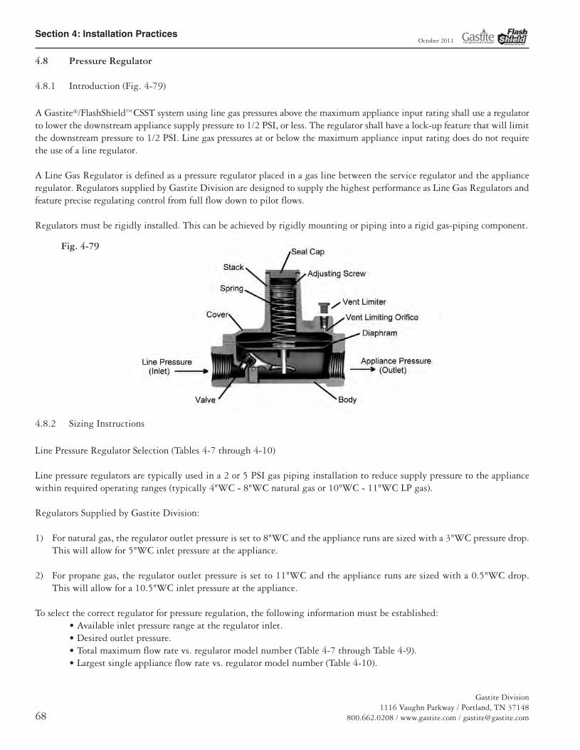
4.8.1 Introduction (Fig. 4-79)
A Gastite®/FlashShield™ CSST system using line gas pressures above the maximum appliance input rating shall use a regulatorto lower the downstream appliance supply pressure to 1/2 PSI, or less. The regulator shall have a lock-up feature that will limitthe downstream pressure to 1/2 PSI. Line gas pressures at or below the maximum appliance input rating does do not requirethe use of a line regulator.
A Line Gas Regulator is defined as a pressure regulator placed in a gas line between the service regulator and the applianceregulator. Regulators supplied by Gastite Division are designed to supply the highest performance as Line Gas Regulators andfeature precise regulating control from full flow down to pilot flows.
Regulators must be rigidly installed. This can be achieved by rigidly mounting or piping into a rigid gas-piping component.
4.8.2 Sizing Instructions
Line Pressure Regulator Selection (Tables 4-7 through 4-10)
Line pressure regulators are typically used in a 2 or 5 PSI gas piping installation to reduce supply pressure to the appliancewithin required operating ranges (typically 4"WC - 8"WC natural gas or 10"WC - 11"WC LP gas).
Regulators Supplied by Gastite Division:
1) For natural gas, the regulator outlet pressure is set to 8"WC and the appliance runs are sized with a 3"WC pressure drop.This will allow for 5"WC inlet pressure at the appliance.
2) For propane gas, the regulator outlet pressure is set to 11"WC and the appliance runs are sized with a 0.5"WC drop.This will allow for a 10.5"WC inlet pressure at the appliance.
To select the correct regulator for pressure regulation, the following information must be established:• Available inlet pressure range at the regulator inlet.• Desired outlet pressure.• Total maximum flow rate vs. regulator model number (Table 4-7 through Table 4-9).• Largest single appliance flow rate vs. regulator model number (Table 4-10).
Fig. 4-79
13133_Gastite_D+I_Guide_Winter2011_5_SEC4 5/30/12 9:39 AM Page 68

Section 4: Installation Practices
Gastite Division1116 Vaughn Parkway / Portland, TN 37148800.662.0208 / www.gastite.com / [email protected] 69
October 2011
Regulator Capacity Tables
Table 4-7
Regulator Capacity for Natural Gas with an 8" w.c. Outlet Pressure
Capacities – 0.64 sp gr gas expressed in CFH (m3/h)
Model Number Outlet Pressure Operating Inlet Pressure
1/2 psi (34 mbar) 3/4 psi (52 mbar) 1 psi (69 mbar) 1-1/2 psi (103) mbar 2 psi (138 mbar)
T325-3-44/Reg8-300 8" w.c. 145 (4.1) 200 (5.7) 250 (7.1) 250 (7.1) 250 (7.1)
T325-5-44/Reg8-600 8" w.c. 335 (9.5) 475 (13.5) 550 (15.6) 550 (15.6) 550 (15.6)
T325-7L-44 8" w.c. 690 (19.5) 970 (27.5) 1000 (28.3) 1000 (28.3) 1000 (28.3)
T325-3L48 (OPD) 8" w.c. 160 (4.5) 200 (5.6) 200 (5.6) 200 (5.6) 200 (5.6)
T325-5AL600 (OPD) 8" w.c. 345 (9.6) 425 (11.9) 425 (11.9) 425 (11.9) 425 (11.9)
T325-7L-210D (OPD) 8" w.c. 650 (18.4) 900 (25.5) 900 (25.5) 900 (25.5) 900 (25.5)
30052-NG 8" w.c. 386 (10.9) 691 (19.6) 848 (24.0) 1063 (30.1) 1155 (32.7)
30053-NG 8" w.c. 386 (10.9) 899 (25.5) 1059 (30.0) 1382 (39.1) 1501 (42.5)
30153-NG 8" w.c. 3189 (90.3) 4638 (131.3) 5297 (150.0) 7230 (204.7) 7891 (223.4)
Capacity value for most typical 2 PSI parallel systems when trunk run is sized to deliver 1 PSI to regulator inlet.
Table 4-8
Regulator Capacity for Natural Gas with an 11 w.c. Outlet Pressure
Capacities – 0.64 sp gr gas expressed in CFH (m3/h)
Model Number Outlet Pressure Operating Inlet Pressure1/2 psi (34 mbar) 3/4 psi (52 mbar) 1 psi (69 mbar) 1-1/2 psi (103) mbar 2 psi (138 mbar)
T325-3-44P/Reg11-300 11" w.c. 93 (2.6) 172 (4.9) 225 (6.4) 250 (7.1) 250 (7.1)
T325-5-44P/Reg11-600 11" w.c. 211 (6.0) 391 (11.1) 511 (14.5) 550 (15.6) 550 (15.6)
T325-7L-44* 11" w.c. 441 (12.5) 816 (23.1) 1000 (28.3) 1000 (28.3) 1000 (28.3)
T325-3L48* (OPD) 11" w.c. 120 (3.4) 200 (5.6) 200 (5.6) 200 (5.6) 200 (5.6)
T325-5AL600* (OPD) 11" w.c. 260 (7.3) 425 (11.9) 425 (11.9) 425 (11.9) 425 (11.9)
T325-7L-210D* (OPD) 11" w.c. 490 (13.9) 821 (23.2) 900 (25.5) 900 (25.5) 900 (25.5)
30052-LP 11" w.c. 297 (8.4) 621 (17.6) 778 (22.0) 967 (27.4) 1155 (32.7)
30053-NG* 11" w.c. 297 (8.4) 807 (22.9) 1093 (31.0) 1297 (36.7) 1501 (42.5)
30153-NG* 11" w.c. 2349 (66.5) 4121 (116.7) 5264 (149.1) 6593 (186.7) 7921 (224.3)
Capacity value for most typical 2 PSI parallel systems when trunk run is sized to deliver 1 PSI to regulator inlet.
*Regulator requires in-field adjustment to obtain output pressure of 11".
Table 4-9Regulator Capacity for Propane with an 11" w.c. Outlet Pressure
Capacities – 1.52 sp gr gas expressed in kBTUhOperating Inlet Pressure
Model Number Outlet Pressure 1/2 psi (34 mbar) 3/4 psi (52 mbar) 1 psi (69 mbar) 1-1/2 psi (103) mbar 2 psi (138 mbar)T325-3-44P/Reg11-300 11" w.c. 147 270 355 395 395T325-5-44P/Reg11-600 11" w.c. 335 620 810 870 870T325-7L-44* 11" w.c. 700 1290 1585 1585 1585T325-3L48* (OPD) 11" w.c. 190 315 315 315 315T325-5AL600* (OPD) 11" w.c. 410 670 670 670 670T 325-7L-210D* (OPD) 11" w.c. 775 1300 1425 1425 142530052-LP 11" w.c. 547 997 1285 1731 198130053-NG* 11" w.c. 712 1296 1671 2251 257530153-NG* 11" w.c. 3724 6784 8741 11775 13470Capacity value for most typical 2 PSI parallel systems when trunk run is sized to deliver 1 PSI to regulator inlet.*Regulator requires in-field adjustment to obtain output pressure of 11".
Table 4-10Largest Single Appliance Served by Regulator
Regulator Natural Gas (CFH) Propane (kBTUh)0.64 SG gas 1.52 SG gas
T325-3-X / RegX-300 140 215T325-5-X / RegX-600 300 460T325-7L-44 900 1380T325-3L48 (OPD) 200 305T325-5AL600 (OPD) 425 650T325-7L-210D (OPD) 900 1380
13133_Gastite_D+I_Guide_Winter2011_5_SEC4 5/30/12 9:39 AM Page 69
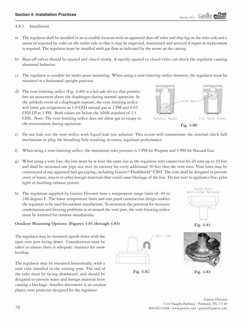
Section 4: Installation Practices
Gastite Division1116 Vaughn Parkway / Portland, TN 37148
800.662.0208 / www.gastite.com / [email protected]
October 2011
4.8.3 Installation
a) The regulator shall be installed in an accessible location with an approved shut-off valve and drip leg on the inlet side and aunion (if required by code) on the outlet side so that it may be inspected, maintained and serviced if repair or replacementis required. The regulator must be installed with gas flow as indicated by the arrow on the casting.
b) Shut-off valves should be opened and closed slowly. A rapidly opened or closed valve can shock the regulator causingabnormal behavior.
c) The regulator is suitable for multi-poise mounting. When using a vent-limiting orifice however, the regulator must bemounted in a horizontal upright position.
d) The vent-limiting orifice (Fig. 4-80) is a fail-safe device that permitsfree air movement above the diaphragm during normal operation. Inthe unlikely event of a diaphragm rupture, the vent limiting orificewill limit gas escapement to 1.0 CFH natural gas at 2 PSI and 0.65CFH LP at 2 PSI. Both values are below the ANSI standard of 2.5CFH. Note: The vent-limiting orifice does not allow gas to escape tothe environment during operation.
e) Do not leak test the vent orifice with liquid leak test solution. This action will contaminate the internal check ballmechanism or plug the breathing hole resulting in erratic regulator performance
f) When using a vent-limiting orifice, the maximum inlet pressure is 2 PSI for Propane and 5 PSI for Natural Gas.
g) When using a vent line, the line must be at least the same size as the regulator vent connection for all runs up to 30 feetand shall be increased one pipe size over its entirety for every additional 30 feet that the vent runs. Vent lines may beconstructed of any approved fuel gas piping, including Gastite®/FlashShield™ CSST. The vent shall be designed to prevententry of water, insects or other foreign materials that could cause blockage of the line. Do not vent to appliance flue, pilotlight or building exhaust system.
h) The regulators supplied by Gastite Division have a temperature range limit of -40 to240 degrees F. The lower temperature limit and rust proof construction design enablesthe regulator to be used for outdoor installations. To minimize the potential for moisturecondensation and freezing problems in or around the vent port, the vent-limiting orificemust be removed for outdoor installations.
Outdoor Mounting Options: (Figures 4-81 through 4-83)
The regulator may be mounted upside down with theopen vent port facing down. Consideration must betaken to ensure there is adequate clearance for snowbuildup.
The regulator may be mounted horizontally, with avent tube installed in the venting port. The end ofthe tube must be facing downward, and should bedesigned to prevent water and foreign material fromcausing a blockage. Another alternative is an outdoorplastic vent protector designed for the regulator.
Fig. 4-80
Fig. 4-81
Fig. 4-82 Fig. 4-83
13133_Gastite_D+I_Guide_Winter2011_5_SEC4 5/30/12 9:39 AM Page 70

Section 4: Installation Practices
Gastite Division1116 Vaughn Parkway / Portland, TN 37148800.662.0208 / www.gastite.com / [email protected] 71
October 2011
4.8.4 Performance
a) A performance test should be conducted while operating all appliances at full load. This will test if adequate pressureis reaching each appliance under full-load conditions. To accomplish this, measure the line pressure at the appliance connectionwhile operating the appliance.
b) The inlet pressure for typical gas appliances under full load conditions should be equal to but not exceeding the appliance’srecommended inlet pressure range. If these pressure ranges cannot be obtained, a slight adjustment to the service regulatoror the pounds-to-inches regulator may be necessary to increase line pressure.
4.8.5 Regulator Outlet Pressure Adjustment
a) Adjustment can be accomplished by first removing the regulator seal cap to expose the adjusting screw. Turning thescrew clockwise will increase outlet pressure, turning it counter-clockwise will decrease pressure.
b) If spring adjustment will not produce the desired outlet pressure, check to make sure the main supply pressure is adequate.If the main supply pressure is adequate, consult factory for other line-regulator options. Do not continue to turn regulatoradjusting screw clockwise if the outlet pressure readings do not continue to increase. This may result in over-firing dueto loss of pressure control, should there be a subsequent increase in inlet pressure.
c) The line regulators can be adjusted with an outlet pressure ranging between 7 and 11 inches water column. The regulatormust be adjusted according to the manufacturers recommended procedure. A pressure gauge mounted just downstreamof the regulator can monitor the set pressure under various loads.
4.8.6 Over-Pressurization Protection
Downstream over-pressure protection must be provided in any gas piping installation where a line-pressure regulator is utilizedfor pressures in excess of 2 PSI to supply appliances rated for 1/2 PSI or less inlet pressure. Special line regulators of suitablecontrol and capacity must be installed in place of the standard line regulator. This regulator contains an integral over-pressureprotection device (OPD) (Fig. 4-84). This special regulator with OPD must be assembled and listed by the manufacturer inaccordance with Z21.80, “Standard for line pressure regulators”. Refer to Tables 4-7 through 4-9 for OPD capacities and sizing.
NOTE: When using regulators other than those specified by Gastite Division for use with the Gastite® system, carefulconsideration must be given to the regulator performance characteristics such as required inlet pressure, flow capacity,the pressure drop through the regulator and available outlet pressure.
Fig. 4-84
13133_Gastite_D+I_Guide_Winter2011_5_SEC4 5/30/12 9:39 AM Page 71
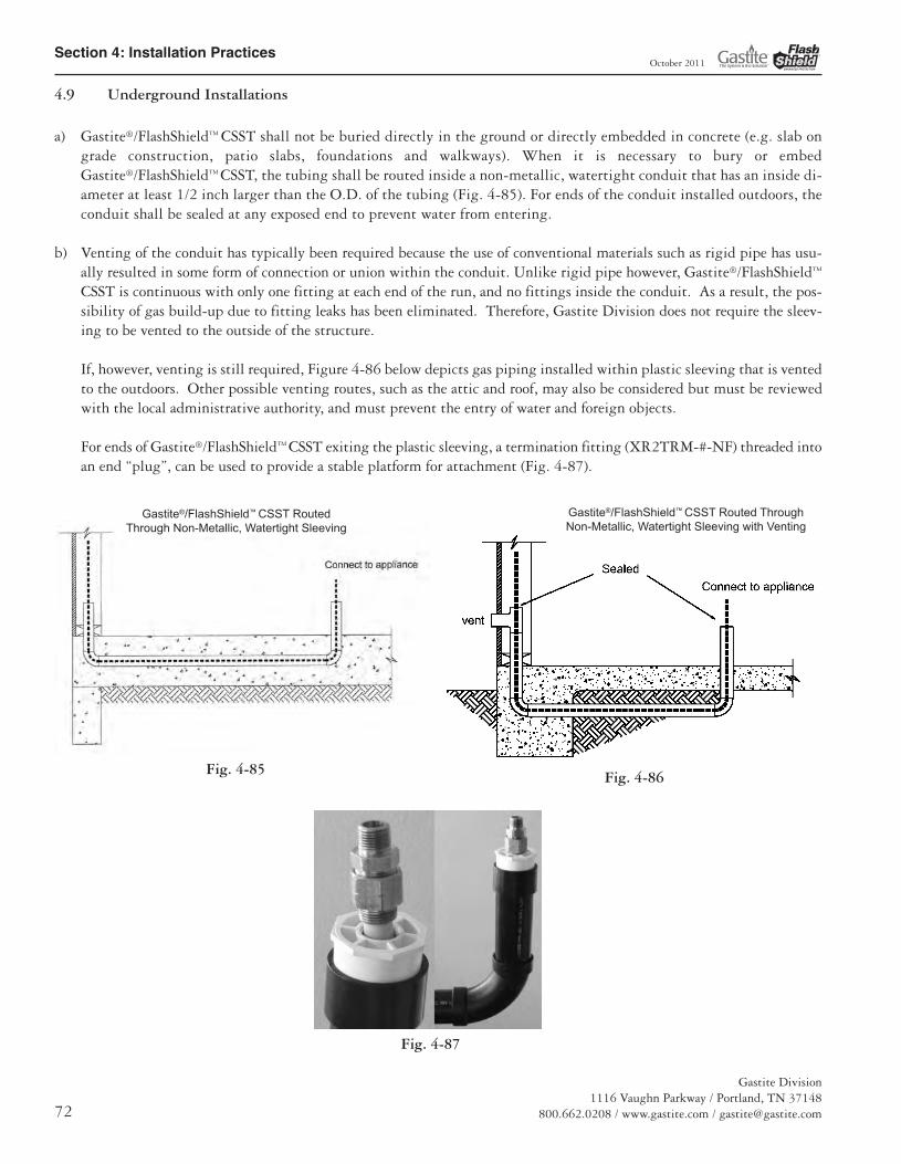
Section 4: Installation Practices
Gastite Division1116 Vaughn Parkway / Portland, TN 37148
800.662.0208 / www.gastite.com / [email protected]
October 2011
4.9 Underground Installations
a) Gastite®/FlashShield™ CSST shall not be buried directly in the ground or directly embedded in concrete (e.g. slab ongrade construction, patio slabs, foundations and walkways). When it is necessary to bury or embedGastite®/FlashShield™ CSST, the tubing shall be routed inside a non-metallic, watertight conduit that has an inside di-ameter at least 1/2 inch larger than the O.D. of the tubing (Fig. 4-85). For ends of the conduit installed outdoors, theconduit shall be sealed at any exposed end to prevent water from entering.
b) Venting of the conduit has typically been required because the use of conventional materials such as rigid pipe has usu-ally resulted in some form of connection or union within the conduit. Unlike rigid pipe however, Gastite®/FlashShield™
CSST is continuous with only one fitting at each end of the run, and no fittings inside the conduit. As a result, the pos-sibility of gas build-up due to fitting leaks has been eliminated. Therefore, Gastite Division does not require the sleev-ing to be vented to the outside of the structure.
If, however, venting is still required, Figure 4-86 below depicts gas piping installed within plastic sleeving that is ventedto the outdoors. Other possible venting routes, such as the attic and roof, may also be considered but must be reviewedwith the local administrative authority, and must prevent the entry of water and foreign objects.
For ends of Gastite®/FlashShield™ CSST exiting the plastic sleeving, a termination fitting (XR2TRM-#-NF) threaded intoan end “plug”, can be used to provide a stable platform for attachment (Fig. 4-87).
Fig. 4-85 Fig. 4-86
Fig. 4-87
Gastite®/FlashShield™ CSST RoutedThrough Non-Metallic, Watertight Sleeving
Gastite®/FlashShield™ CSST Routed ThroughNon-Metallic, Watertight Sleeving with Venting
13133_Gastite_D+I_Guide_Winter2011_5_SEC4 5/30/12 9:39 AM Page 72

Section 4: Installation Practices
Gastite Division1116 Vaughn Parkway / Portland, TN 37148800.662.0208 / www.gastite.com / [email protected] 73
October 2011
4.10 Electrical Bonding of Gastite®/FlashShield™ CSST
a) Unlike Gastite®, there are no additional bonding requirements for FlashShield™ imposed by the manufacturer’s installationinstructions. FlashShield™ is to be bonded in accordance with the National Electrical Code NFPA 70 Article 250.104 inthe same manner as the minimum requirements for rigid metal piping. However, installers must always adhere to any localrequirements that may conflict with these instructions.
b) Direct bonding of Gastite® CSST is required for all gas-piping systems incorporating Gastite® CSST whether or not theconnected gas equipment is electrically powered. This requirement is provided as part of the manufacturer's instruction forsingle-family and multi-family buildings. A person knowledgeable in electrical system design, the local electrical code andthese requirements should specify the bonding for commercial applications.
Gastite® CSST installed inside or attached to a building or structureshall be electrically continuous and direct bonded to the electricalground system of the premise in which it is installed. The gas pipingsystem shall be considered to be direct bonded when installed inaccordance with the following:
The piping is permanently and directly connected to the electricalservice equipment enclosure, the grounded conductor at the electricalservice, the grounding electrode conductor (where of sufficient size)or to one or more of the grounding electrodes used. For single andmulti-family structures, a single bond connection shall be madedownstream of the individual gas meter for each housing unit andupstream of any CSST connection. The bonding conductor shall beno smaller than a 6 AWG copper wire or equivalent. The bondingjumper shall be attached in an approved manner in accordance withNEC Article 250.70 and the point of attachment for the bondingjumper shall be accessible. Bonding/grounding clamps shall beinstalled in accordance with its listing per UL 467 and shall makemetal-to-metal contact with the piping. This bond is in additionto any other bonding requirements as specified by local codes.
For attachment to the CSST gas piping system, a single bondingclamp must be attached to either a segment of steel pipe, a rigidpipe component or to the Gastite brass hex fitting. For attachmentto a segment of steel pipe or a rigid pipe component any bondingclamp listed to UL467 may be used. For attachment to a Gastitehex fitting, clamps manufactured by Erico (part numberCWP1JSH for 3/8" & 1/2", CWP2JSH for 3/4" thru 1- 1/4" andCWP3JSH for 1 1/2" & 2") must be used. The corrugated stainlesssteel tubing portion of the gas piping system shall not be used asthe point of attachment of the bonding conductor at any locationalong its length under any circumstances. See examples providedin Figures 4-88 and 4-89.
Proper bonding and grounding will reduce the risk of damage andfire from a lightning strike. Lightning is a highly destructive force.Even a nearby lightning strike that does not strike a structuredirectly can cause all electrically conductive systems in the structure to become energized. If these systems are not adequatelybonded, the difference in electrical potential between the systems may cause the charge to arc from one system to another.Arcing can cause damage to CSST. Direct bonding and grounding as set forth above will reduce the risk of arcing andrelated damage over a non direct bonded system.
Depending upon conditions specific to the location of the structure in which the Gastite system is being installed,including but not limited to whether the area is prone to lightning, the owner of the structure should consider whether alightning protection system is necessary or appropriate. Lightning protection systems are beyond the scope of this bulletin,but are covered by NFPA 780, the Standard for the Installation of Lightning Protection Systems and other standards.
Fig. 4-88 - Bonding Clamp on Steel PipeSegment or Gastite Stub-Out.
(Remove any paint or coating on pipe surfacebeneath clamp location)
Bonding Wire
Bonding Clamp
Bonding Wire
BondingClamp
CSST Fitting
Black Pipe Component orGastite Stub-Out
Fig. 4-89 - Bonding Clamp on Gastite CSST fitting.(Clamp #CWP1JSH, CWP2JSH or CWP3JSH)
13133_Gastite_D+I_Guide_Winter2011_5_SEC4 5/30/12 9:39 AM Page 73
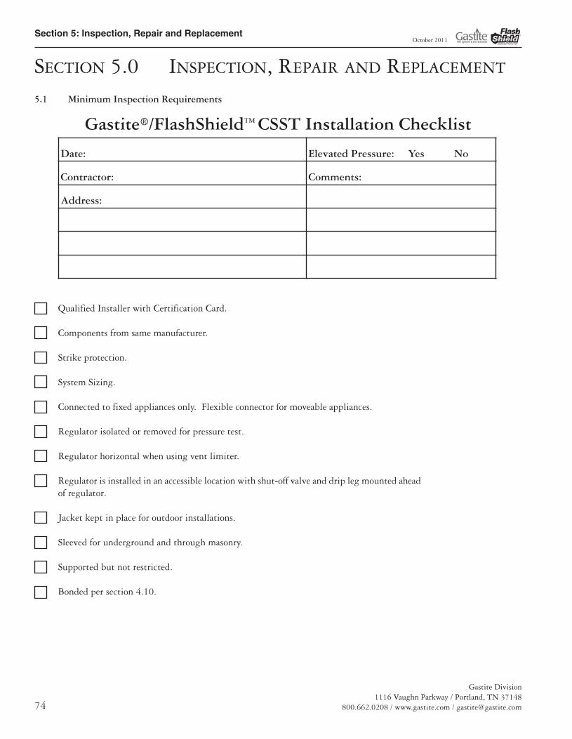
Section 5: Inspection, Repair and Replacement
Gastite Division1116 Vaughn Parkway / Portland, TN 37148
800.662.0208 / www.gastite.com / [email protected]
October 2011
SECTION 5.0 INSPECTION, REPAIR AND REPLACEMENT
5.1 Minimum Inspection Requirements
Gastite®/FlashShield™ CSST Installation Checklist
Qualified Installer with Certification Card.
Components from same manufacturer.
Strike protection.
System Sizing.
Connected to fixed appliances only. Flexible connector for moveable appliances.
Regulator isolated or removed for pressure test.
Regulator horizontal when using vent limiter.
Regulator is installed in an accessible location with shut-off valve and drip leg mounted aheadof regulator.
Jacket kept in place for outdoor installations.
Sleeved for underground and through masonry.
Supported but not restricted.
Bonded per section 4.10.
Date: Elevated Pressure: Yes No
Contractor: Comments:
Address:
13133_Gastite_D+I_Guide_Winter2011_6_SEC5 5/30/12 11:15 AM Page 74
Section 5: Inspection, Repair and Replacement
Gastite Division1116 Vaughn Parkway / Portland, TN 37148800.662.0208 / www.gastite.com / [email protected] 75
October 2011
5.2 Installation Checklist Description
Corrugated Stainless Steel Tubing (CSST) has been design certified by the Canadian Standards Association since 1990 for useas a fuel gas piping system. Gastite®/FlashShield™ CSST has been tested per ANSI LC1 as required for approval and as anapproved gas piping material in the National Fuel Gas Code-NFPA 54 & 58, the International Fuel Gas Code-ICC, and withthe Uniform Plumbing Code-IAPMO.
Approval: Conditions and Requirements
A flexible gas piping system using Gastite®/FlashShield™ CSST must be installed in accordance with all local building codesand the manufacturer’s instructions. The following checklist is designed to assist the local administrative authority to performan inspection of a fuel gas piping system using corrugated stainless steel tubing.
1. Gastite®/FlashShield™ flexible gas piping may only be installed by a qualified installer who has successfully completed the manufacturer’scertification training program. A manufacturer’s certification card is required to purchase and install Gastite®/FlashShield™ flexiblegas piping.
2. Only the components provided or specified by the Gastite Division (including strike protection) as part of the piping system are tobe used in the installation.
3. Gastite®/FlashShield™ CSST routed in a location which is concealed, constrained and within 3 inches of a potential threat must beprotected against damage using protection devices listed in the manufacturer’s Design and Installation Guide.
4. Sizing of the flexible gas piping system must be performed using capacity tables found in the manufacturer’s Design and InstallationGuide or other code approved CSST capacity tables.
5. Gastite®/FlashShield™ CSST should not be connected to moveable appliances. Connections to moveable appliances such as ranges andclothes dryers should be accomplished with a flexible appliance connector.
6. The Gastite®/FlashShield™ flexible gas piping system must be pressure tested for leaks during rough construction in accordance withall local codes. In the absence of local requirements, test in accordance with NFPA 54, National Fuel Gas Code, which is 1-1/2 timesthe maximum working pressure but not less than 3 PSI. To subject the entire Gastite®/FlashShield™ CSST system to pressure test,the pressure regulators should be isolated or removed.
7. Regulators are suitable for multi-poise mounting. When using a vent-limiting device however, the regulator must be mounted in ahorizontal upright position.
8. A manifold assembly utilizing a pounds-to-inches regulator shall include a ball valve ahead of the regulator and installed in anaccessible location so that the regulator can be inspected, maintained and serviced if repair or replacement is required.
9. When installed outdoors, the external jacket shall remain intact as much as possible. Exposed portions of the stainless steel tubingshall be wrapped to provide protection from corrosive threats.
10. For installations buried underground, under concrete/asphalt or embedded in concrete, Gastite®/FlashShield™ CSST must be routed ina non-metallic watertight conduit which has an inside diameter at least 1/2 in. larger than the outside diameter of the tubing. Underconcrete/asphalt slab, sleeved CSST must be buried in accordance with all local codes. No mechanical joints are permitted within the conduit.
11. Installation must be properly supported to not only keep the job professional and organized but also to prevent excess strain on thebends and fittings. Supports installed in addition to the practices outlined by Gastite Division, restricts the tubing and increasessusceptibility to strike damage.
12. Gas piping systems must be properly bonded to the structure's electrical service. A qualified professional following the NECapproved methods as outlined in section 4.10 shall perform the bonding installation.
13. Gastite® CSST must be physically separated from other continuous metallic systems in accordance with section 4.3 of this guide.
13133_Gastite_D+I_Guide_Winter2011_6_SEC5 5/30/12 11:15 AM Page 75

Section 5: Inspection, Repair and Replacement
Gastite Division1116 Vaughn Parkway / Portland, TN 37148
800.662.0208 / www.gastite.com / [email protected]
October 2011
5.3 Repair of Damaged CSST
5.3.1 Determine Damage
Crushed, dented or kinked tubing may result in restricted flow conditions. Use the following guidelines to determine theseverity of damage and whether repair or replacement is necessary.
a) Gastite®/FlashShield™ CSST gas tubing must be repaired if damaged by puncture of any kind, e.g. nails, screws, drillbits, etc.
b) No repairs or replacement of the tubing is necessary if the Gastite®/FlashShield™ CSST tubing is only slightly dented dueto impact or crushing and the overall crush depth is less than 1/3 the diameter of the tubing. Minimal flow reduction willoccur at this limited damage level.
c) Repair or replacement is necessary if the overall crush depth is greater than 1/3 the diameter of the tubing. Restricted flowmay occur at this damage level.
d) Gastite®/FlashShield™ CSST tubing bent beyond its minimum bend radius so that a crease or kink remains must be repaired.Restricted flow may occur at this damage level.
5.3.2 Method of Repair
A line splice can be made, but if the tubing run is short and easily accessible, the preferred repair method is to replace theentire length. Often, a tubing run can be replaced faster than repairing the damaged section. The Gastite®/FlashShield™
mechanical joint fittings can be removed and easily re-attached. This is the preferred method because it does not add anyadditional fitting joints to the system.
Where repairs or replacements involve only the Gastite®/FlashShield™ CSST, the tubing can be joined with standard pipecouplings or Gastite®/FlashShield™ CSST coupling (Fig. 5-1).
Where repairs or replacements involve CSST systems of different manufacturers, the systems can be joined through standardpipe couplings and each manufacturer’s recommended CSST fitting (Fig. 5-2).
Fig. 5-1
Fig. 5-2
13133_Gastite_D+I_Guide_Winter2011_6_SEC5 5/30/12 11:15 AM Page 76

Section 6: Pressure / Leakage Testing
Gastite Division1116 Vaughn Parkway / Portland, TN 37148800.662.0208 / www.gastite.com / [email protected] 77
October 2011
SECTION 6.0 PRESSURE/LEAKAGE TESTING
6.1 General Guidelines for Pressure Testing
a) The final installation must be inspected and tested for leaks in accordance with the local/state codes. In the absence of localcodes, installation must be in accordance with the current edition of the National Fuel Gas Code, ANSI Z223.1/NFPA-54(USA), or Installation Codes CSA-B149.1 (Canada). Pressure testing must comply with these guidelines or local codes.When local codes are more stringent, local codes must be followed.
b) Pressure testing must be performed during rough construction of the facility (before interior walls are finished).This will permit a more complete inspection of the piping system during the pressure testing.
c) Do not connect appliances or pressurize with fuel gas until after the pressure test has been passed.
d) All gas outlets for appliance connections should be capped during pressure testing.
6.2 Elevated Pressure Systems
If an elevated pressure system requires a pressure test of 10 PSI or greater, the regulator must be removed or isolated prior topressure testing.
The test may be performed as a one-part test replacing the regulator with a suitable jumper pipe length for pressure testingthe entire system (Figures 6-1 and 6-2).
Or a two-part test may be performed as shown in Figure 6-3:
• The first test is performed on the elevated pressure section, between the meter connection and the pounds-to-inches lineregulator.
• The second test is performed on the low-pressure section, between the outlet of the pounds-to-inches line regulator andthe gas appliance outlets.
• For a two-part test, it is important to remember to close both gas shut-off valves to avoid damage to the regulator.
• When opening the shut-off valves it is important to open them slowly. A quickly opened valve can shock the regulatorand cause abnormal regulator behavior.
Fig. 6-1 Fig. 6-2 Fig. 6-3
13133_Gastite_D+I_Guide_Winter2011_7_SEC6 5/30/12 11:20 AM Page 77

Section 6: Pressure / Leakage Testing
Gastite Division1116 Vaughn Parkway / Portland, TN 37148
800.662.0208 / www.gastite.com / [email protected]
October 2011
6.3 Appliance Connection Leakage Check Procedure
After the final pressure test, inspection and final construction is complete (finished interior walls), connect the appliances to thesystem. This connection can be made using an approved flexible connector for movable appliances, or withGastite®/FlashShield™ CSST tubing or rigid black pipe for fixed appliances. Turn the gas on at the meter and inspect for leak-age before operating the appliances.
a) Connections made at the appliances should be leak checked with a chloride-free bubble solution. Leak check solutionsmust comply with ASTM E515, or be labeled as non-corrosive.
b) Before placing the appliances in operation, the tubing system should be purged. This displaces the air in the system withfuel gas. Be sure to vent into a well-ventilated area.
NOTE: Leak test solutions may cause corrosion in some types of material in the gas tubing system, be sure to waterrinse after the test and thoroughly dry all contacted material. Also, the vent limiter should not be leak tested witha liquid test solution. This will contaminate the internal ball check mechanism or plug the breathing hole, result-ing in erratic regulator operation.
13133_Gastite_D+I_Guide_Winter2011_7_SEC6 5/30/12 11:20 AM Page 78

Section 8: Definitions
Gastite Division1116 Vaughn Parkway / Portland, TN 37148800.662.0208 / www.gastite.com / [email protected] 99
SECTION 8.0 DEFINITIONS
APPLIANCE (EQUIPMENT) – Any device which utilizes gas as a fuel or raw material to produce light, heat, power, refrigeration orair conditioning.
APPROVED – Acceptable to the authority having jurisdiction.
AUTHORITY HAVING JURISDICTION – The organization, office or individual responsible for “approving” equipment, aninstallation or procedure.
BONDING (BONDED) – The permanent joining of metallic parts to form an electrically conductive path that ensures electricalcontinuity and the capacity to conduct safely any current likely to be imposed. As per the National Electrical Code.
CAPACITY, FLOW – As used in this standard, the amount of a specified gas that will flow through a specific length and configurationof tubing, a manifold, fitting or other component at a specified pressure drop in a fixed period of time.
CONCEALED GAS TUBING – Gas tubing, which, when in place in a finished building, would require removal of permanentconstruction to gain access to the piping.
CONNECTOR, GAS APPLIANCE – A factory-fabricated assembly of gas conduit and related fittings designed to convey gaseousfuel, and used for making connections between a gas supply piping outlet and the gas to an appliance. It is equipped at each end forattachment to standard taper pipe threads.
DIRECT BONDING – Bonding, as above, where the electrical connection is made using a clamp and wire at the piping connecteddirectly to the electrical panel. Refer to Section 4.10 Electrical Bounding of Gastite®/FlashShield™ CSST.
EFFECTIVE GROUND-FAULT CURRENT PATH – An intentionally constructed, permanent, low impedance electricallyconductive path designed and intended to carry under ground fault conditions from the point of a ground fault on a wiring system to the electrical supply source.
EQUIVALENT HYDRAULIC DIAMETER (EHD) – A theoretical size, which reflects the hydraulic performance of the tubing.It is not true physical measurement.
EXPOSED GAS TUBING – Gas tubing which will be in view in the finished structure.
FUEL GAS – A commonly distributed gas used for fuel such as natural gas, manufactured gas, undiluted liquefied petroleum gas(vapor phase only), liquefied petroleum gas-air mixtures of these gases (includes propane and butane).
GAS UTILIZATION EQUIPMENT – Any device that utilizes gas as a fuel or raw material or both.
INCHES OF WATER COLUMN ("WC) – Method of pressure measured in inches of water column by a manometer or pressure gauge.Commonly used in the gas industry when the pressure is less than 1 PSI.
LEAK TEST SOLUTION – A solution of commercial leak-testing fluids may be used. The use of soap buds or household detergentsand water is not considered a satisfactory leak-test fluid for a bubble test, because of a lack of sensitivity due to masking by foam. Thefluid should be capable of being applied free of bubbles so that a bubble appears only at a leak. The fluid selected should not bubbleexcept in response to a leak.
LISTED – Equipment or materials including a list published by an organization acceptable to the authority having jurisdiction andconcerned with product evaluation that maintains periodic inspection of production of listed equipment or materials and whose listingstates either that the equipment or materials meets appropriate standards or has been tested and found suitable for use in a specifiedmanner.
October 2011
13133_Gastite_D+I_Guide_Winter2011_9_SEC8 5/30/12 11:35 AM Page 99

Section 8: Definitions
Gastite Division1116 Vaughn Parkway / Portland, TN 37148
800.662.0208 / www.gastite.com / [email protected]
LOCKUP PRESSURE, REGULATOR – The system pressure, immediately downstream of the regulator, at which the regulator valvewill completely close (leak tight) under no-flow conditions to prevent the downstream pressure from exceeding a predetermined level.
MAXIMUM ACTUAL OPERATING PRESSURE – The maximum pressure existing in a piping system during a normal annual operating cycle.
OVER-PRESSURE PROTECTION DEVICE (OPD) – System component that is intended to protect all downstream componentsfrom high pressures in the event of a system failure. OPDs are required in gas systems using more than 2psi line pressure.
PIPING SYSTEM – As used in this standard, an assembly of corrugated stainless steel tubing and tubing connection fittings, intended for field assembly and installation in residential or commercial buildings to distribute fuel gas to gas utilization equipmentwithin the building. The piping system may also include a gas pressure regulator(s), a shutoff valve(s), tube shielding devices, distribution manifold(s), and other approved devices or components.
PLENUM – A plenum is an enclosed portion of the building structure that is designed to allow air movement, and thereby serve aspart of an air distribution system.
PRESSURE DROP – The loss in static pressure of flowing fuel gas due to friction or other flow resistance in tubing, fittings, valves,regulators, or other devices in the piping system.
QUALIFIED INSTALLER – Any individual, firm, corporation or company which either in person or through a representative is engaged in and is responsible for the installation or replacement of building gas piping systems, who is experienced in such work, familiar with all precautions required, and has complied with all the requirements of the authority having jurisdiction.
QUICK-DISCONNECT DEVICE – A hand-operated device which provides a means for connecting and disconnecting an applianceor an appliance connector to a gas supply, and which is equipped with an automatic means to shut off the gas supply when the device isdisconnected.
REGULATOR, PRESSURE – A device placed in a gas line for reducing, controlling and maintaining the pressure in that portion ofthe piping system downstream of the device.
SHIELDING DEVICE – A component of the piping system used to protect the installed corrugated tubing from accidental punctureby nails, screws or similar hardware at concealed tubing support points.
STRIKER PLATE – A special type of shielding device used when concealed tubing is run through wall studs, floor and ceiling joistsor other structural members where tubing movement is restricted.
VALVE, SHUTOFF – A device used in piping to control the gas supply to any section of the piping system or to an appliance.
October 2011
13133_Gastite_D+I_Guide_Winter2011_9_SEC8 5/30/12 11:35 AM Page 100