Embed Size (px)
Citation preview

Design andDesign andImplementation ofImplementation ofSignal ProcessingSignal Processing
Systems:Systems:An IntroductionAn Introduction

2
OutlineOutline• Course Objectives and Outline, Conduct• What is signal processing?• Implementation Options and Design issues:
– General purpose (micro) processor (GPP)• Multimedia enhanced extension (Native signal processing)
– Programmable digital signal processors (PDSP)• Multimedia signal processors (MSP)
– Application specific integrated circuit (ASIC)– Re-configurable signal processors

Issues in DSPIssues in DSPArchitectures and ProjectsArchitectures and Projects
• Provide students with a global view of embeddedmicro-architecture implementation options anddesign methodologies for multimedia signalprocessing.
• The interaction between the algorithm formulationand the underlying architecture that implements thealgorithm will be focused:– Formulate algorithm for match architecture.
– Design novel architecture to match algorithm.
Issues to be treated inIssues to be treated inprojectsprojects
• Signal processing computingalgorithms
• Algorithm representations
• Algorithm transformations:– Retiming, unfolding
– Folding
• Systolic array and designmethodologies
• Mappling algorithms to arraystructures
• Low power design
• Native signal processing andmultimedia extension
• Programmable DSPs
• Very Long Instruction Word(VLIW) Architecture
• Re-configurable computing &FPGA
• Signal Processing arithmetics:CORDIC, and distributedarithmetic.
• Applications: Video, audio,communication

What is Signal?What is Signal?• A SIGNAL is a measurement of a physical quantity
of certain medium.
• Examples of signals:– Visual patterns (written documents, picture, video,
gesture, facial expression)
– Audio patterns (voice, speech, music)
– Change patterns of other physical quantities: temperature,EM wave, etc.
• Signal contains INFORMATION!
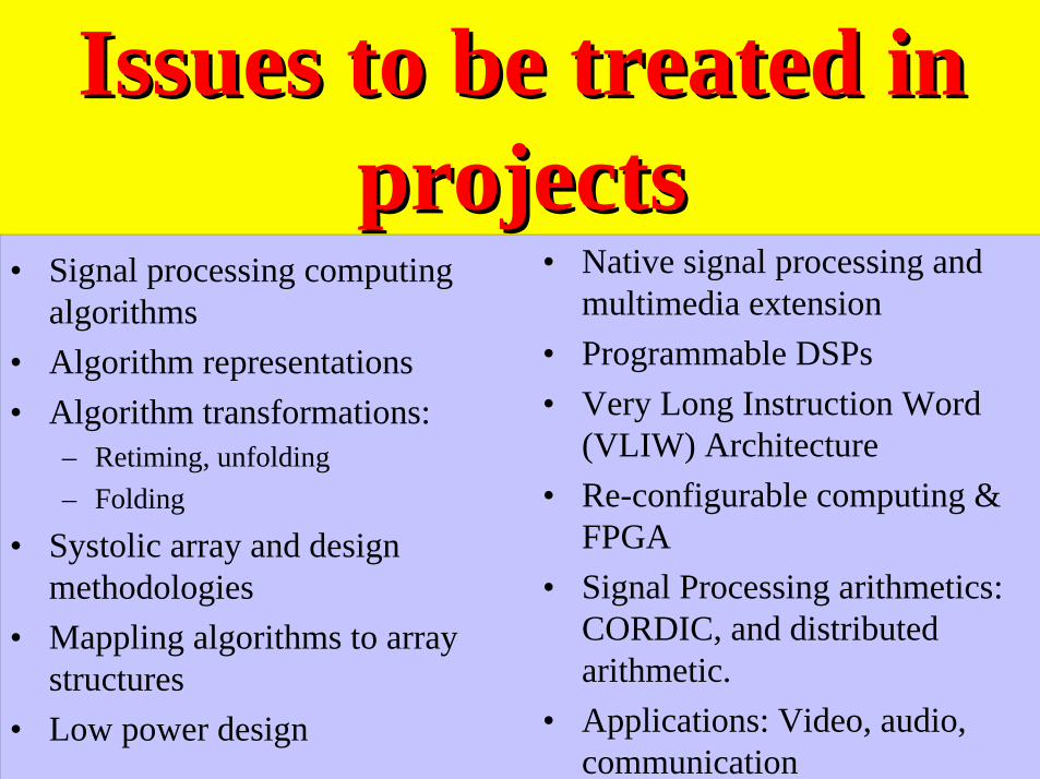
Medium and ModalityMedium and Modality• Medium:
– Physical materials that carry the signal.
– Examples: paper (visual patterns, handwriting, etc.), Air(sound pressure, music, voice), various video displays(CRT, LCD)
• Modality:– Different modes of signals over the same or different
media.
– Examples: voice, facial expression and gesture.

What is Signal Processing?What is Signal Processing?• Ways to manipulate
signal in its originalmedium or an abstractrepresentation.
• Signal can be abstractedas functions of time orspatial coordinates.
• Types of processing:– Transformation– Filtering– Detection– Estimation– Recognition and
classification– Coding (compression)– Synthesis and reproduction– Recording, archiving– Analyzing, modeling
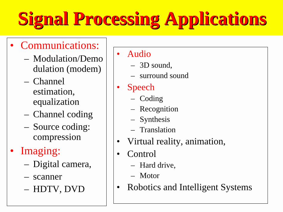
Signal Processing ApplicationsSignal Processing Applications• Communications:
– Modulation/Demodulation (modem)
– Channelestimation,equalization
– Channel coding– Source coding:
compression
• Imaging:– Digital camera,– scanner– HDTV, DVD
• Audio– 3D sound,– surround sound
• Speech– Coding– Recognition– Synthesis– Translation
• Virtual reality, animation,• Control
– Hard drive,– Motor
• Robotics and Intelligent Systems

Digital Signal ProcessingDigital Signal Processing• Signals generated via
physical phenomenon areanalog in that– Their amplitudes are defined
over the range ofreal/complex numbers
– Their domains arecontinuous in time or space.
• Processing analog signalrequires dedicated,specialhardware.
• Digital signal processingconcerns processingsignals using digitalcomputers.– A continuous time/space
signal must be sampled toyield countable signalsamples.
– The real-(complex)valued samples must bequantized to fit intointernal word length.
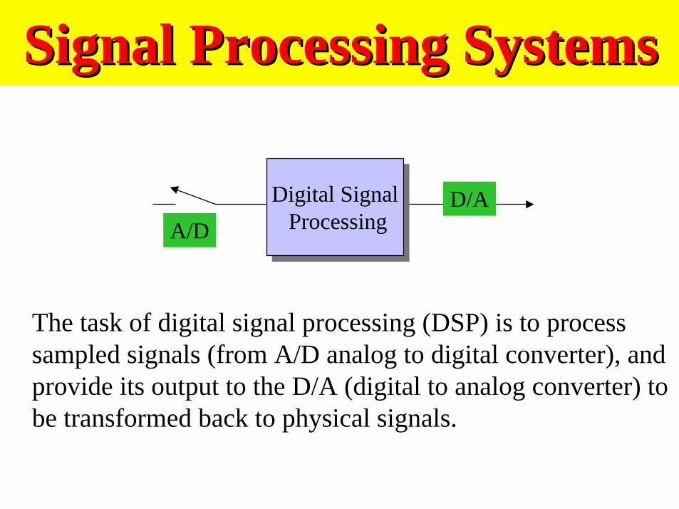
Signal Processing SystemsSignal Processing Systems
The task of digital signal processing (DSP) is to processsampled signals (from A/D analog to digital converter), andprovide its output to the D/A (digital to analog converter) tobe transformed back to physical signals.
Digital Signal Processing
Digital Signal ProcessingA/D
D/A
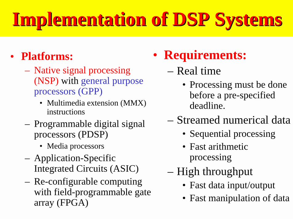
Implementation of DSP SystemsImplementation of DSP Systems
• Platforms:– Native signal processing
(NSP) with general purposeprocessors (GPP)
• Multimedia extension (MMX)instructions
– Programmable digital signalprocessors (PDSP)
• Media processors
– Application-SpecificIntegrated Circuits (ASIC)
– Re-configurable computingwith field-programmable gatearray (FPGA)
• Requirements:– Real time
• Processing must be donebefore a pre-specifieddeadline.
– Streamed numerical data• Sequential processing• Fast arithmetic
processing
– High throughput• Fast data input/output• Fast manipulation of data
How Fast is Enough for DSP?How Fast is Enough for DSP?
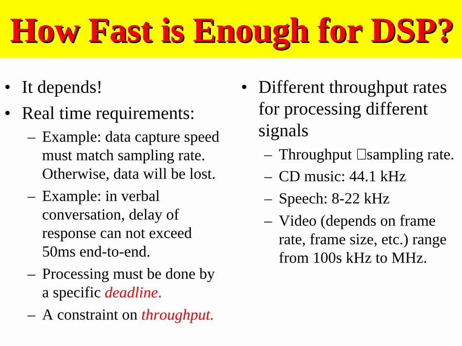
• It depends!
• Real time requirements:– Example: data capture speed
must match sampling rate.Otherwise, data will be lost.
– Example: in verbalconversation, delay ofresponse can not exceed50ms end-to-end.
– Processing must be done bya specific deadline.
– A constraint on throughput.
• Different throughput ratesfor processing differentsignals– Throughput ∝ sampling rate.
– CD music: 44.1 kHz
– Speech: 8-22 kHz
– Video (depends on framerate, frame size, etc.) rangefrom 100s kHz to MHz.
Early Signal Processing SystemsEarly Signal Processing Systems
• Implemented witheither main framecomputer or specialpurpose computers.
• Batch processingrather than real time,streamed dataprocessing.
• Accelerate processingspeed is of mainconcern.
• Key approach:– Faster hardware
– Faster algorithms
• Faster algorithms– Reduce the number of
arithmetic operations
– Reduce the number of bits torepresent each data
– Most important example:Fast Fourier Transform

Computing FourierComputing FourierTransformTransform
• To compute the N frequencies
{X(k); 0 ≤ k ≤ N−1}requires N2 complexmultiplications
• Fast Fourier Transform– Reduce the computation to
O(N log2 N) complexmultiplications
– Makes it practical to processlarge amount of digital data.
– Many computations can be“Speed-up” using FFT
– Dawn of modern digitalsignal processing
∑
∑−
=
−
=
=
−=
1
0
1
0
]2
exp[)(1
)(
]2
exp[)()(
N
k
N
n
N
nkkX
Nnx
N
nknxkX
π
π
Discrete Fourier Transform
Evolution of Micro-ProcessorEvolution of Micro-Processor
• Micro-processorsimplemented a centralprocessing unit on asingle chip.
• Performance improvedfrom 1MFLOP (1983)to 1GFLOP or above
• Word length (# bits forregister, data bus, addr.Space, etc) increasesfrom 4 bits to 64 bitstoday.
• Clock frequency increasesfrom 100KHz to 1GHz
• Number of transistorsincreases from 1K to 50M
• Power consumptionincreases much slower withthe use of lower supplyvoltage: 5 V drops to 1.5V
Native Signal ProcessingNative Signal Processing• Use GPP to perform signal
processing task with noadditional hardware.– Example: soft-modem, soft DVD
player, soft MPEG player.
• Reduce hardware cost!• May not be feasible for
extremely high throughputtasks.
• Interfering with other tasks asGPP is tied up with NSP tasks.
• MMX (multimedia extensioninstructions): specialinstructions for acceleratingmultimedia tasks.
• May share same data-path withother instructions, or work onspecial hardware modules.
• Make use sub-word parallelismto improve numericalcalculation speed.
• Implement DSP-specificarithmetic operations, eg.Saturation arithmetic ops.
ASIC: Application Specific ICsASIC: Application Specific ICs
• Custom or semi-custom ICchip or chip sets developedfor specific functions.
• Suitable for high volume,low cost productions.
• Examples: MPEG codec,3D graphic chip, etc.
• ASIC becomes popular dueto availability of ICfoundry services.
• Fab-less design housesturn innovative design intoprofitable chip sets usingCAD tools.
•• Design automationDesign automation is a keyenabling technology tofacilitate fast design cycleand shorter time to marketdelay.

Programmable Digital SignalProgrammable Digital SignalProcessors (Processors (PDSPPDSPs)s)
• Micro-processors designedfor signal processingapplications.
• Special hardware supportfor:– Multiply-and-Accumulate
(MAC) ops– Saturation arithmetic ops– Zero-overhead loop ops– Dedicated data I/O ports– Complex address calculation
and memory access– Real time clock and other
embedded processingsupports.
• PDSPs were developedto fill a market segmentbetween GPP and ASIC:– GPP flexible, but slow– ASIC fast, but inflexible
• As VLSI technologyimproves, role of PDSPchanged over time.– Cost: design, sales,
maintenance/upgrade– Performance
Multimedia Signal ProcessorsMultimedia Signal Processors
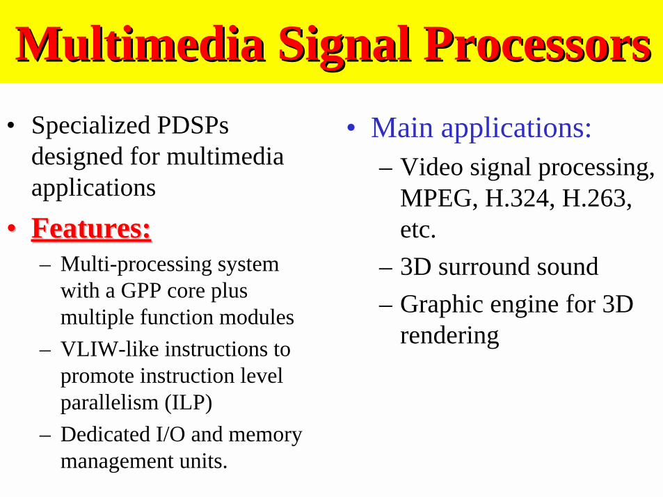
• Specialized PDSPsdesigned for multimediaapplications
•• Features:Features:– Multi-processing system
with a GPP core plusmultiple function modules
– VLIW-like instructions topromote instruction levelparallelism (ILP)
– Dedicated I/O and memorymanagement units.
• Main applications:– Video signal processing,
MPEG, H.324, H.263,etc.
– 3D surround sound
– Graphic engine for 3Drendering

Re-configurableRe-configurableComputing using FPGAComputing using FPGA
• FPGA (Field programmablegate array) is a derivative ofPLD (programmable logicdevices).
• They are hardwareconfigurable to behavedifferently for differentconfigurations.
• Slower than ASIC, but fasterthan PDSP.
• Once configured, it behaves likean ASIC module.
• Use of FPGA– Rapid prototyping: run
fractional ASIC speedwithout fab delay.
– Hardware accelerator: usingthe same hardware to realizedifferent function modulesto save hardware
– Low quantity systemdeployment

Characteristics and Impact of VLSICharacteristics and Impact of VLSI
• Characteristics– High density:
• Reduced feature size:0.25µm -> 0.16 µm
• % of wire/routing areaincreases
– Low power/high speed:• Decreased operating voltage:
1.8V -> 1V• Increased clock frequency:
500 MHz-> 1GH.
– High complexity:• Increased transistor count:
10M transistors and higher• Shortened time-to-market
delay: 6-12 months
• The term VLSI (Very LargeScale Integration) is coined inlate 1970s.
• Usage of VLSI:– Micro-processor
• General purpose• Programmable DSP• Embedded µ-controller
– Application-specific ICs– Field-Programmable Gate
Array (FPGA)
• Impacts:– Design methodology– Performance– Power

Design IssuesDesign Issues• Given a DSP application,
which implementationoption should be chosen?
• For a particularimplementation option,how to achieve optimaldesign? Optimal in termsof what criteria?
• Software design:– NSP/MMX, PDSP/MSP– Algorithms are implemented as
programs.– Often still require
programming in assembly levelmanually
• Hardware design:– ASIC, FPGA– Algorithms are directly
implemented in hardwaremodules.
• S/H Co-design: System leveldesign methodology.
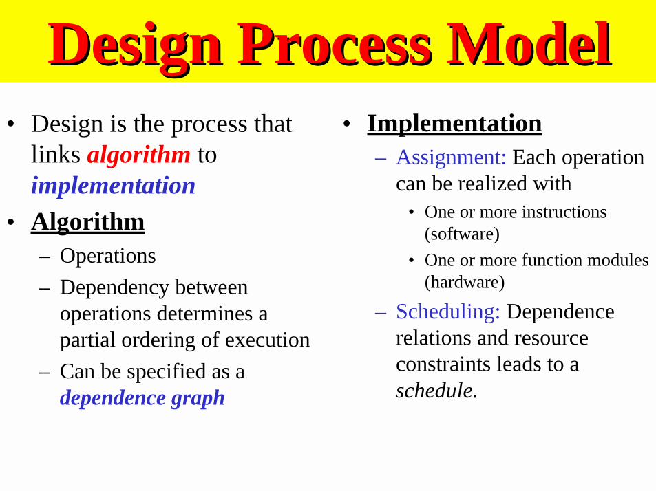
Design Process ModelDesign Process Model• Design is the process that
links algorithm toimplementation
• Algorithm– Operations
– Dependency betweenoperations determines apartial ordering of execution
– Can be specified as adependence graph
• Implementation– Assignment: Each operation
can be realized with• One or more instructions
(software)
• One or more function modules(hardware)
– Scheduling: Dependencerelations and resourceconstraints leads to aschedule.

A Design Example …A Design Example …Consider the algorithm:
Program:y(0) = 0
For k = 1 to n Do
y(k) = y(k-1)+ a(k)*x(k)
End
y = y(n)
• Operations:– Multiplication
– Addition
• Dependency– y(k) depends on y(k-1)
– Dependence Graph:
∑=
=n
k
kxkay1
)()(
*
+
a(1) x(1)
*
+
a(2) x(2)
*
+
a(n) x(n)
y(0) y(n)
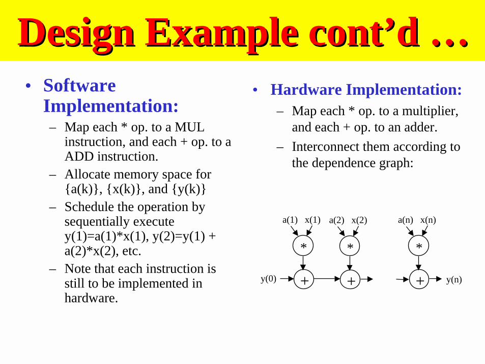
Design Example cont’d …Design Example cont’d …• Software
Implementation:– Map each * op. to a MUL
instruction, and each + op. to aADD instruction.
– Allocate memory space for{a(k)}, {x(k)}, and {y(k)}
– Schedule the operation bysequentially executey(1)=a(1)*x(1), y(2)=y(1) +a(2)*x(2), etc.
– Note that each instruction isstill to be implemented inhardware.
• Hardware Implementation:– Map each * op. to a multiplier,
and each + op. to an adder.
– Interconnect them according tothe dependence graph:
*
+
a(1) x(1)
*
+
a(2) x(2)
*
+
a(n) x(n)
y(0) y(n)

ObservationsObservations• Eventually, an
implementation isrealized with hardware.
• However, by using thesame hardware torealize differentoperations at differenttime (scheduling), wehave a softwareprogram!
• Bottom line –Hardware/ software co-design. There is acontinuation betweenhardware and softwareimplementation.
• A design must exploreboth simultaneously toachieve bestperformance/cost trade-off.
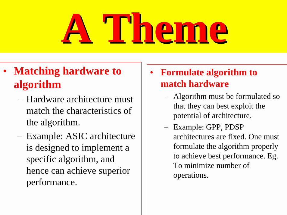
A ThemeA Theme• Matching hardware to
algorithm– Hardware architecture must
match the characteristics ofthe algorithm.
– Example: ASIC architectureis designed to implement aspecific algorithm, andhence can achieve superiorperformance.
• Formulate algorithm tomatch hardware– Algorithm must be formulated so
that they can best exploit thepotential of architecture.
– Example: GPP, PDSParchitectures are fixed. One mustformulate the algorithm properlyto achieve best performance. Eg.To minimize number ofoperations.
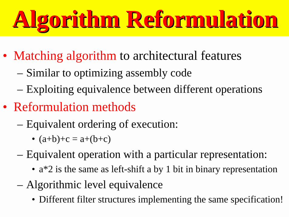
Algorithm ReformulationAlgorithm Reformulation• Matching algorithm to architectural features
– Similar to optimizing assembly code
– Exploiting equivalence between different operations
• Reformulation methods– Equivalent ordering of execution:
• (a+b)+c = a+(b+c)
– Equivalent operation with a particular representation:• a*2 is the same as left-shift a by 1 bit in binary representation
– Algorithmic level equivalence• Different filter structures implementing the same specification!
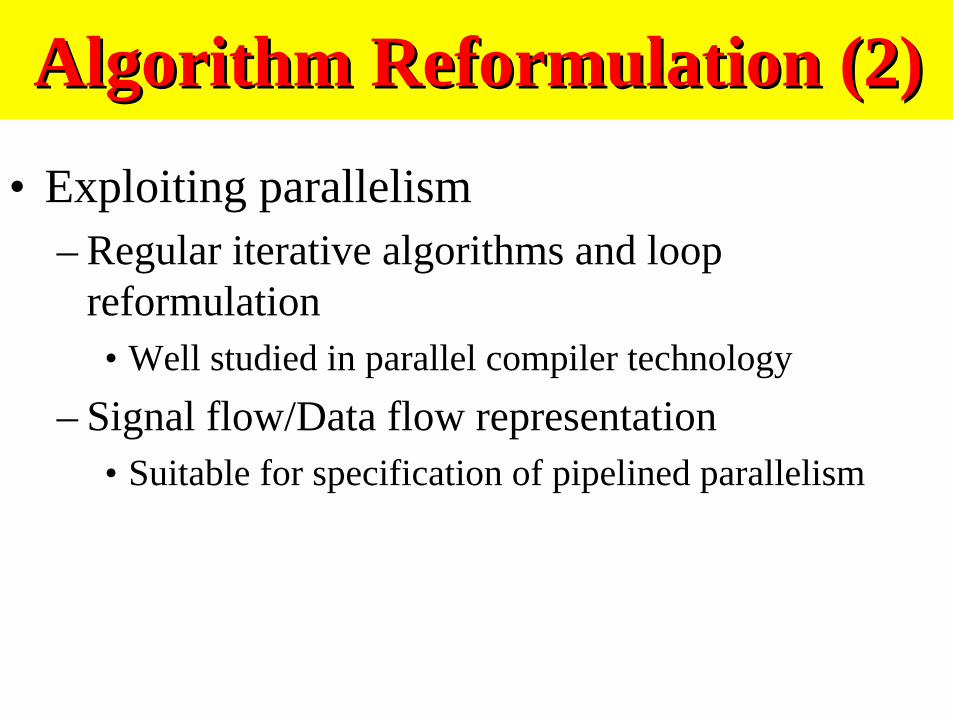
Algorithm Reformulation (2)Algorithm Reformulation (2)
• Exploiting parallelism– Regular iterative algorithms and loop
reformulation• Well studied in parallel compiler technology
– Signal flow/Data flow representation• Suitable for specification of pipelined parallelism
15
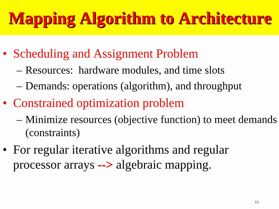
Mapping Algorithm to ArchitectureMapping Algorithm to Architecture
• Scheduling and Assignment Problem– Resources: hardware modules, and time slots
– Demands: operations (algorithm), and throughput
• Constrained optimization problem– Minimize resources (objective function) to meet demands
(constraints)
• For regular iterative algorithms and regularprocessor arrays --> --> algebraic mapping.

Mapping Algorithms toMapping Algorithms toArchitecturesArchitectures
• Irregular multi-processor architecture:– linear programming
– Heuristic methods
– Algorithm reformulation for recursions.
• Instruction level parallelism– MMX instruction programming
– Related to optimizing compilation.

14
ArithmeticArithmetic• CORDIC
– Compute elementary functions
• Distributed arithmetic– ROM based implementation
• Redundant representation– eliminate carry propagation
• Residue number system

Low Power DesignLow Power Design
• Device level low power design
• Logic level low power design
• Architectural level low power design
• Algorithmic level low power design
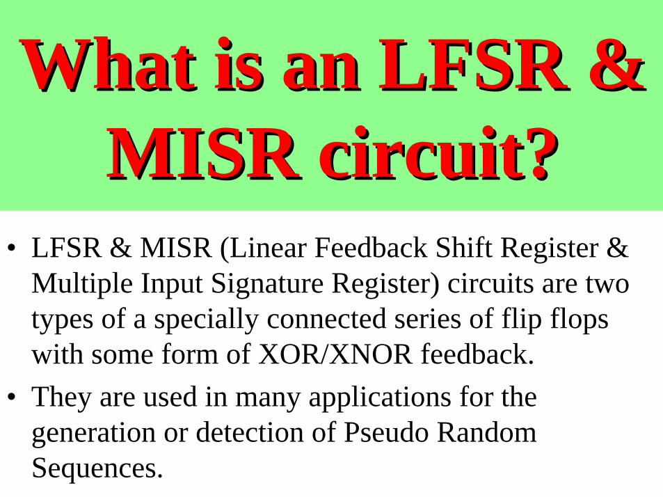
What is an LFSR &What is an LFSR &MISR circuit?MISR circuit?
• LFSR & MISR (Linear Feedback Shift Register &Multiple Input Signature Register) circuits are twotypes of a specially connected series of flip flopswith some form of XOR/XNOR feedback.
• They are used in many applications for thegeneration or detection of Pseudo RandomSequences.
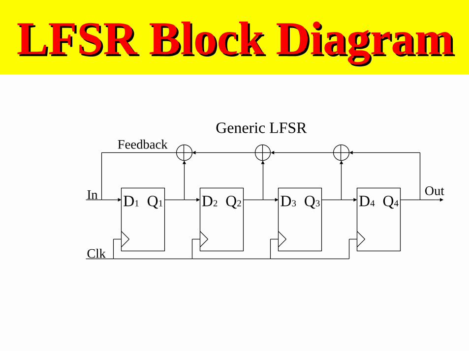
LFSR Block DiagramLFSR Block Diagram
D1 Q1 D2 Q2 D3 Q3 D4 Q4
Clk
In
Feedback
Out
Generic LFSR

LFSR Block Diagram (LFSR Block Diagram (contcont.).)
Clk
In
Feedback
Out
Maximal Length LFSR (n = 4)
By Changing the Feedback path to “tap” only certain FF’s, a Maximal Length Sequence can be produced.
D1 Q1 D2 Q2 D3 Q3 D4 Q4
Polynomial: 1 + x3 + x4
Maximal Length: (2n - 1) = (24 - 1) = (16 - 1) = 15
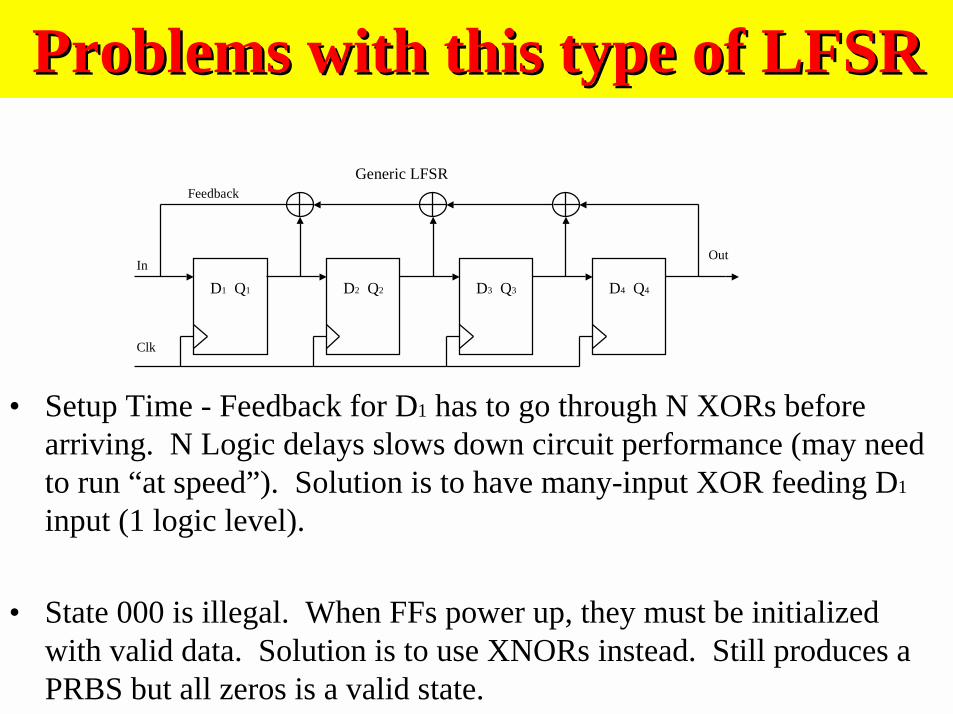
Problems with this type of LFSRProblems with this type of LFSR
D1 Q1 D2 Q2 D3 Q3 D4 Q4
Clk
In
Feedback
Out
Generic LFSR
• Setup Time - Feedback for D1 has to go through N XORs beforearriving. N Logic delays slows down circuit performance (may needto run “at speed”). Solution is to have many-input XOR feeding D1
input (1 logic level).
• State 000 is illegal. When FFs power up, they must be initializedwith valid data. Solution is to use XNORs instead. Still produces aPRBS but all zeros is a valid state.
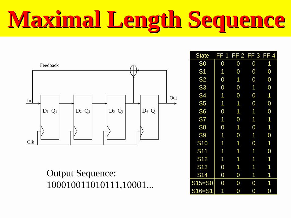
Maximal Length SequenceMaximal Length Sequence
Clk
In
Feedback
Out
D1 Q1 D2 Q2 D3 Q3 D4 Q4
State FF 1 FF 2 FF 3 FF 4S0 0 0 0 1S1 1 0 0 0S2 0 1 0 0S3 0 0 1 0S4 1 0 0 1S5 1 1 0 0S6 0 1 1 0S7 1 0 1 1S8 0 1 0 1S9 1 0 1 0
S10 1 1 0 1S11 1 1 1 0S12 1 1 1 1S13 0 1 1 1S14 0 0 1 1
S15=S0 0 0 0 1S16=S1 1 0 0 0
Output Sequence:100010011010111,10001...

MISR Block DiagramMISR Block Diagram
D1 Q1 D2 Q2 D3 Q3 D4 Q4
Feedback
Out
Generic MISR
D1 D2 D3 D4
Multiple Inputs (4-bit wide): {D1,D2,D3,D4}
LFSR & MISR Applications:LFSR & MISR Applications:
• BIST (Built-in Self Test) of logic devices.
• Cyclic Encoding/Decoding (Cyclic RedundancyCheck)
• Pseudo Noise Generator
• Pseudo Random Binary Sequence Generator
• Spread Spectrum (CDMA) applications
Built-In Self Test (BIST)Built-In Self Test (BIST)
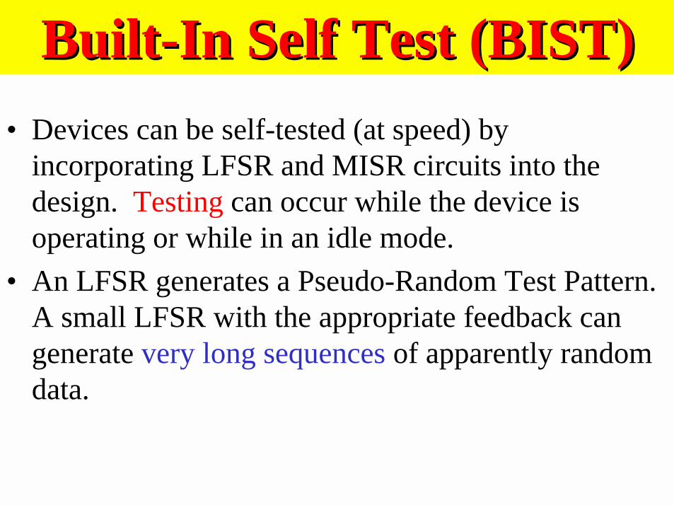
• Devices can be self-tested (at speed) byincorporating LFSR and MISR circuits into thedesign. Testing can occur while the device isoperating or while in an idle mode.
• An LFSR generates a Pseudo-Random Test Pattern.A small LFSR with the appropriate feedback cangenerate very long sequences of apparently randomdata.
Built-In Self Test (BIST) (Built-In Self Test (BIST) (contcont.).)
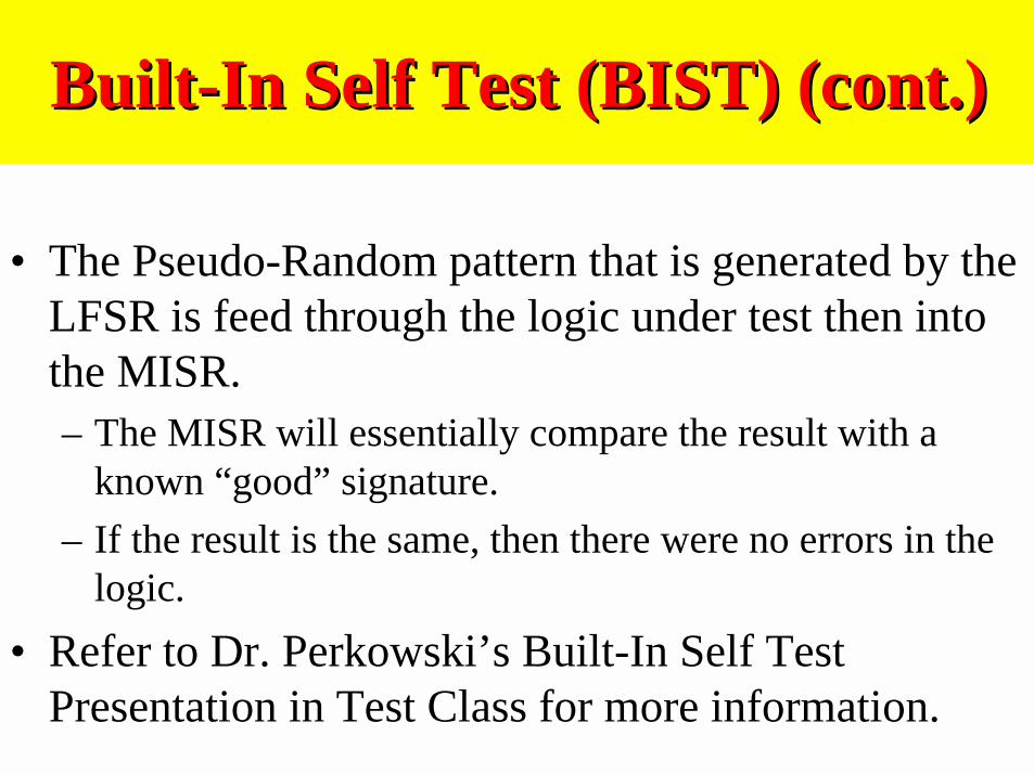
• The Pseudo-Random pattern that is generated by theLFSR is feed through the logic under test then intothe MISR.– The MISR will essentially compare the result with a
known “good” signature.
– If the result is the same, then there were no errors in thelogic.
• Refer to Dr. Perkowski’s Built-In Self TestPresentation in Test Class for more information.

Spread Spectrum PRBSSpread Spectrum PRBS• Because PN signals have good auto-correlation, they
are used in Code Division Multiple Access SpreadSpectrum Communication Systems.
• Pseudo Random Noise Sequences are used toeffectively “spread” the overall bandwidth of a CDMAsignal.
• For every data bit that is to be transmitted, a PRNS issubstituted. The Information rate remains the same,but the new bit rate is dramatically increased.
1 -> 100010011010111…0 -> 011101100101000…
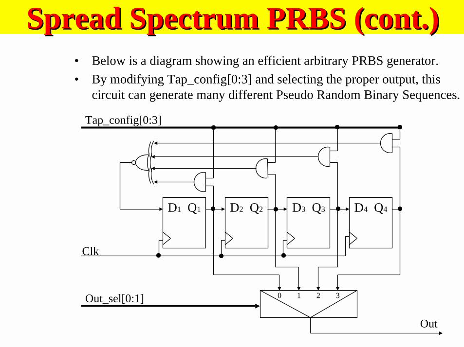
Spread Spectrum PRBS (Spread Spectrum PRBS (contcont.).)• Below is a diagram showing an efficient arbitrary PRBS generator.
• By modifying Tap_config[0:3] and selecting the proper output, thiscircuit can generate many different Pseudo Random Binary Sequences.
D1 Q1 D2 Q2 D3 Q3 D4 Q4
Clk
Out
Tap_config[0:3]
Out_sel[0:1] 0 1 2 3
Practical LFSR and MISRPractical LFSR and MISRcircuitscircuits
• LFSR and MISR circuits are used in many applications.
• As technology continues to advance, more and more deviceswill be developed that will utilize the unique properties ofthese powerful circuits.
• Built-In Self Test and Spread Spectrum (CDMA)applications are but a few of the many places where LFSRand MISR circuits are used.

PracticalPracticalCombinationalCombinational
MultipliersMultipliers
What is a What is a combinationalcombinationalmultiplier?multiplier?
• A combinational multiplier circuit is comprised ofmultiple shift registers, an adder, and some controllogic.
• A multiply is performed by addition and shifting.
• Typical generic multipliers are slow, often takingmultiple clock cycles to computer a product.
• Computers without dedicated multipliers mustperform a multiply using this method.
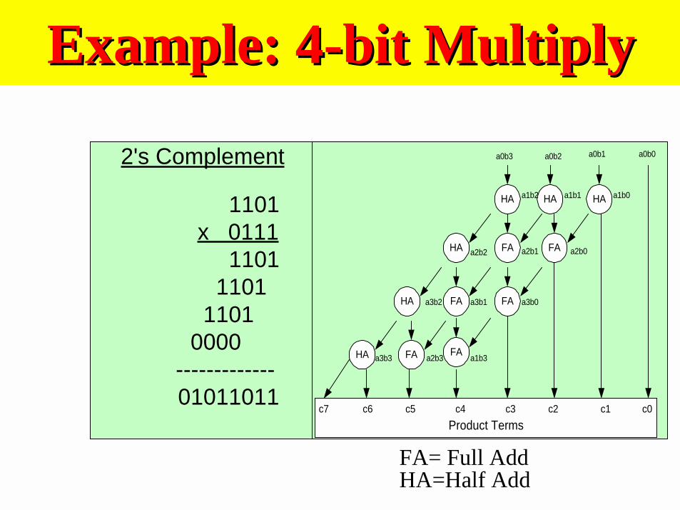
Example: 4-bit MultiplyExample: 4-bit Multiply
1101 x 0111 1101
1101 1101
0000 ------------- 01011011
2's Complement
HA
FA
FA
FAHA
FA
HA HA
FAFAHA
a0b1a0b3 a0b0a0b2
a1b0a1b1
a2b0a2b1a2b2
a3b0
a1b2
a3b1
a1b3
a3b2
a2b3a3b3
Product Termsc0c1c2c3c4c5c6c7
HA
FA= Full AddHA=Half Add

Generic Serial Multiplier Block DiagramGeneric Serial Multiplier Block Diagram
Digital Systems Principals and Applications, Ronald J. Tocci, Prentice Hall1995, pg 280
So what’s wrong with thisSo what’s wrong with thistype of multiplier?type of multiplier?
• For an N x N generic Multiplier, it takes N clockcycles to get a product. That’s too slow!
• Inefficient use of hardware.

Types of MultipliersTypes of Multipliers• Standard Binary Multiplier (ones complement, twos
complement, universal, etc...)
• Re-coded Multipliers (Canonical Signed Digit, Booth, etc…)
• Serial / Parallel Multipliers
• Iterative Cellular Array Multipliers (Wallace, Pezaris,
Baugh-Wooley, etc…)
• ROM based Multiplication Networks (Constant
Coefficient Multipliers, Logarithmic, etc...)
Multiplier ApplicationsMultiplier Applications• General Purpose Computing
• Digital Signal Processing– Finite Impulse Response Filters
– Convolution

ROM BasedROM BasedConstant Coefficient MultiplierConstant Coefficient Multiplier
• With some DSP applications, such as FIR filtergeneration and convolution, where the coefficientsremain unchanged and high speed is a requirement,using a look-up table approach to multiplication is quitecommon.
• Using the known coefficients, every possible product iscalculated and programmed into a look-up table. (ROMor RAM)
• The unknown multiplicand (input data) is used as anaddress to “look up” the product.
• This method results in very high speed multiplies,however it requires large amounts of storage space.
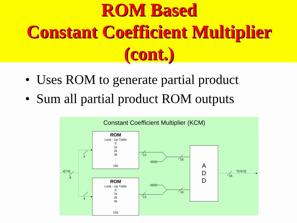
ROM BasedROM BasedConstant Coefficient MultiplierConstant Coefficient Multiplier
((contcont.).)• Uses ROM to generate partial product
• Sum all partial product ROM outputs
ROMLook - Up Table
01k2k3k..
15k
ROMLook - Up Table
01k2k3k..
15k
ADD
16
12
12
0000
000016
16
Y[15:0]
4
4
8
x[7:0]
Constant Coefficient Multiplier (KCM)

Practical Combinatorial MultipliersPractical Combinatorial Multipliers
• Generic Shift/Add type multipliers are SLOW!
• People will always be searching for methods ofperforming faster multiplies.
• Multipliers are used in many areas.
• General purpose math for PCs and DSP (FIRfilters, Convolution, etc…) applications are justa few of the places were multipliers are utilized.

ReferencesReferences• Digital Systems Principals and Applications, Ronald J. Tocci, Prentice
Hall 1995, pg 278-282
• Xilinx Application Note (XAPP 054). Constant CoefficientMultipliers for XC4000E. http://www.xilinx.com/xapp/xapp054.pdf
• Altera Application Note (AN 82). Highly Optimized 2-D convolversin FLEX Devices. http://www.altera.com/document/an/an082_01.pdf
• Computer Arithmetic Principles, Architecture, and Design, KaiHwang, John Wiley & Sons, Inc. 1979, pg129-212

ReferencesReferences• Dr. Perkowski. Design for Testability Techniques (Built-In Self-Test)
presentation.http://www.ee.pdx.edu/~mperkows/CLASS_TEST_99/BIST.PDF
• Digital Communications Fundamentals and Applications, BernardSklar, Prentice Hall 1988, Pg 290-296, Pg 546-555
• Xilinx Application Note (XAPP 052). Efficient Shift Registers, LFSRCounters, and Long Pseudo-Random Sequence Generators.http://www.xilinx.com/xapp/xapp052.pdf
• Sun Microsystems’ sponsored EDAcafe.com website. Chapter 14 -Test. http://www.dacafe.com/Book/CH14/CH14.htm

SourcesSources•Yu Hen Hu
•Andrew Iverson, ECE 572