Embed Size (px)
Citation preview
International Journal of Soft Computing and Engineering (IJSCE) ISSN: 2231-2307, Volume-4 Issue-4, September 2014
73 Published By: Blue Eyes Intelligence Engineering & Sciences Publication Pvt. Ltd.
Design and Implementation of Practical Induction Heating Cooker
A. K. M. Al-Shaikhli, Amanoeel Thomas Meka
Abstract — Induction heating is a famous technology and very usually used for cooking appliances because of its high-energy efficiency. This paper presents a practical design procedure for small induction heating devices. Also, we model the magneto thermal phenomena of the system by a finite element method (FEM) to determine the temperature evolution in the bottom of the pan, taking into account the nonlinearity of the system.
Index Terms— Finite element method, magneto thermal devices, a.c. resistance, metallic object.
I. INTRODUCTION
In common, induction heating is a contactless technique of generating heat energy in a conductive material by producing eddy current losses in the work piece from an external variable high-frequency power source. Over the last ten years, induction cooking is much used, because of its advantages [1] compared to conventional heating system (resistance, gas, etc...), in particular direct heating of pan without thermal inertia. All induction heating (IH) applied systems are developed using electromagnetic induction which was first discovered by Michael Faraday in 1831[2]. Electromagnetic induction refers to the phenomenon by which electric current is generated in a closed circuit by the fluctuation of current in another circuit placed next to it. The basic principle of induction heating, which is an applied form of Faraday’s discovery, is the fact that AC current flowing through a circuit affects the magnetic movement of a secondary circuit located near it[3]. The fluctuation of current inside the primary circuit provided the answer as to how the mysterious current is generated in the neighboring secondary circuit. Faraday’s discovery led to the development of electric motors, generators, transformers, and wireless communications devices[4]. Its application, however, has not been flawless. Heat loss, which occurs during the electromagnetic induction process, was a major headache undermining the overall functionality of a system. This heat loss, could be turned into productive heat energy in an electric heating system. Many industries have benefited from this new breakthrough by implementing induction heating for furnacing, quenching, and welding. In these applications, induction heating has made it easier to set the heating parameters without the need of an additional external power source. This substantially reduces heat loss while maintaining a more convenient working environment. Absence of any physical contact to heating devices precludes unpleasant electrical accidents. High energy density is achieved by generating sufficient heat energy within a relatively short period of time. Manuscript Received on September 2014.
Prof. Dr. A. K. M. Al-Shaikhli , Department of Electrical Engineering, UniversityofTechnology,Baghdad,Iraq.
Amanoeel Thomas Meka, Department of Electrical Engineering, University of Technology ,Baghdad ,Iraq.
The demand for better quality, safe and less energy consuming products is rising. Products include rice cookers and pans. Safe, efficient and quick heating appliances attract more customers. Induction cooking has become of widespread use because of some specific features such as safety, heating speed and efficiency. These are mainly due to the induction cooking working principle, which is based on local heating generated by eddy current at the bottom of the pan. New types of manufacturing processes have made it possible to obtain multi-layer vessel structures, enjoying a very efficient heating behavior. The main goal of this technology is to achieve a uniform cooking temperature and a high magnetic coupling[5].Beside several advantages there are still some issues such as high cost and power consumption. Research efforts up to now have consisted on one hand in optimizing the induction system, looking for new layouts of both inductor and vessel[6-10] and, on the other hand, in optimizing the performance of the power supply [11-13].Basically a domestic induction appliance consists of a high frequency (HF) inductor, i.e. a copper Litz wire tape placed below the cooking surface, and a metallic vessel, which may be made of different layers of magnetic stainless steel and highly conductive materials like aluminum or copper. The power electronic supply consists of ac/dc rectifier, a bus filter, and a resonant inverter[8]. In resonant inverters zero-voltage or zero-current switching are attained when the R-L-C circuit, representing the induction system and the matching capacitance, is resonating. In this condition power switching losses are minimized enabling high frequency operations, with limited size and cost of the device. In this framework the analysis of the equivalent impedance of the coupled inductor-vessel system becomes mandatory in order to obtain an optimal design of supply systems[14].
II. GOVERNING EQUATIONS AND SENSITIVITY
CALCULATION
A. Review Stage
Submit your manuscript electronically for review. The subject under consideration is a small induction heating cooker which is a coupled problem with a quasi static magnetic field and a steady-state heat conduction. The governing equations of this coupled problem are as follows[5]:
(1)
(2)
is the magnetic vector potential and
Design and Implementation of Practical Induction Heating Cooker
74
Published By: Blue Eyes Intelligence Engineering & Sciences Publication Pvt. Ltd.
is the source current density.
is the temperature and
,is the magnetic permeability, conductivity, and thermal conductivity, respectively.
is the heat source, which can be calculated by the induced eddy current. The finite element discretization is applied to both electromagnetic and heat systems and produces the linear system matrices. Note that the heat conduction system has the mixed convection boundary condition[5, 15]:
(3)
h: is the heat transfer coefficient The design sensitivity of the induction heating device is calculated using both electromagnetic and thermal system equations [5, 16]:
The objective function F is defined as[5]
Where is the desired temperature at node and
is the actual temperature at that node.
III. INDUCTION COOKER : DESIGN AND WORKING
PRINCIPLE
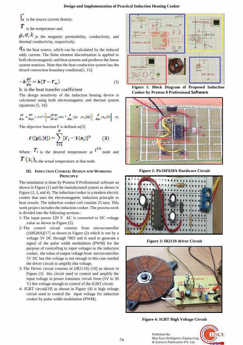
The simulation is done by Proteus 8 Professional software as shown in Figure (1) and the manufactured system as shown in Figure (2, 3, and 4). The induction cooker is a modern electric cooker that uses the electromagnetic induction principle to heat vessels. The induction cooker coil consists 25 turn. This work project includes the induction cooker. The process work is divided into the following sections : 1- The input power 220 V AC is converted to DC voltage
value as shown in Figure (5). 2- The control circuit consists from microcontroller
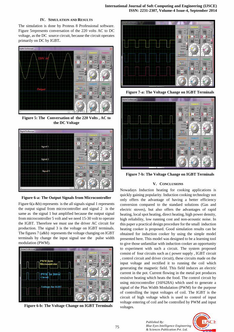
(16f628A)[17] as shown in Figure (2) which is run by a voltage 5V DC through 7805 and is used to generate a signal of the pulse width modulation (PWM) for the purpose of controlling to input voltages to the induction cooker, the value of output voltage from microcontroller 5V DC but this voltage is not enough in this case needed the driver circuit to amplify this voltage.
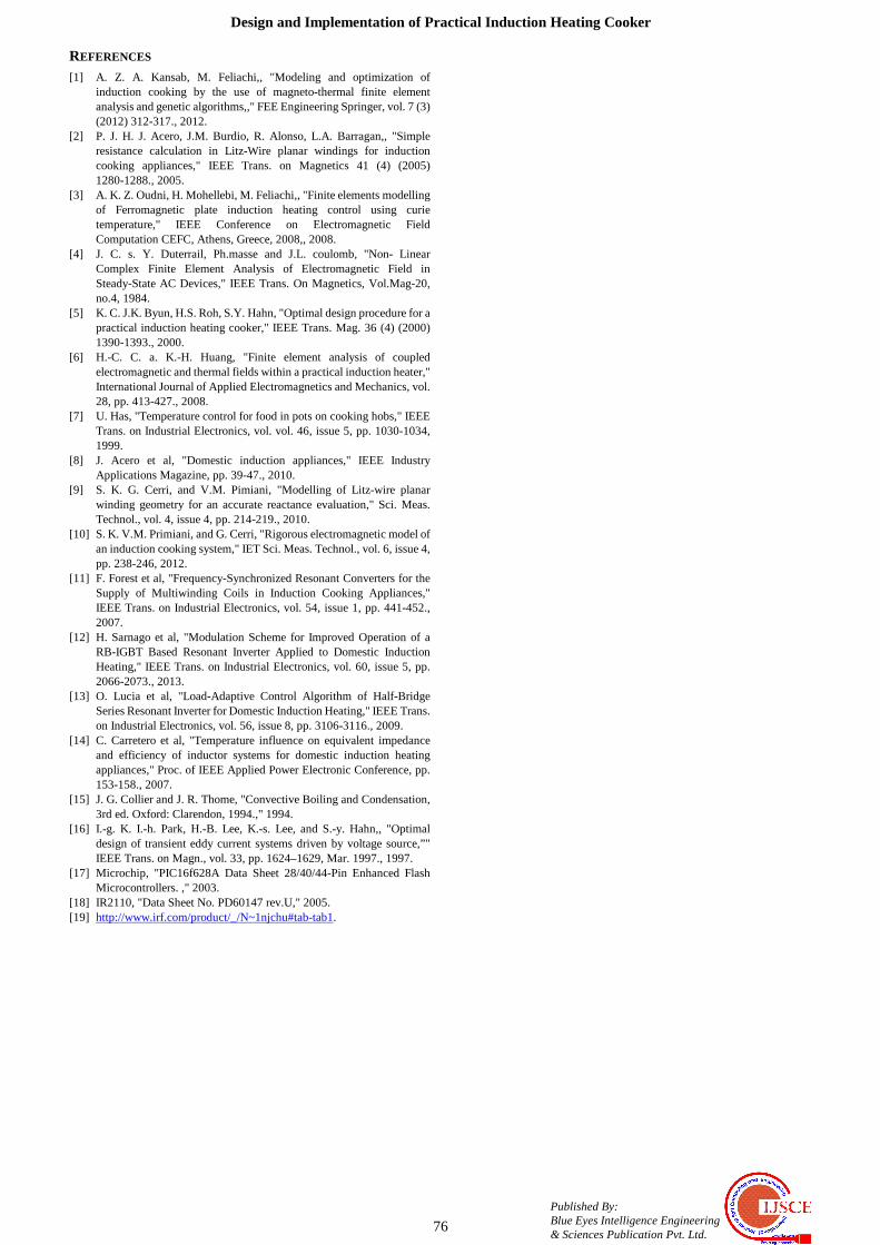
3- The Driver circuit consists of (IR2110) [18] as shown in Figure (3) this circuit used to control and amplify the input voltage in power transistor circuit from (5V to 30 V) this voltage enough to control of the IGBT circuit.
4- IGBT circuit[19] as shown in Figure (4) is high voltage circuit used to control the input voltage for induction cooker by pulse width modulation (PWM).
Figure 1: Block Diagram of Proposed Induction Cooker by Proteus 8 Professional Software
Figure 2: Pic16F628A Hardware Circuit
Figure 3: IR2110 driver Circuit
Figure 4: IGBT High Voltage Circuit
International Journal of Soft Computing and Engineering (IJSCE) ISSN: 2231-2307, Volume-4 Issue-4, September 2014
75 Published By: Blue Eyes Intelligence Engineering & Sciences Publication Pvt. Ltd.
IV. SIMULATION AND RESULTS
The simulation is done by Proteus 8 Professional software. Figure 5represents conversation of the 220 volts AC to DC voltage, as the DC source circuit, because the circuit operates primarily on DC by IGBT.
Figure 5: The Conversation of the 220 Volts , AC to the DC Voltage
Figure 6-a: The Output Signals from Microcontroller
Figure 6(a &b) represents is the all signals signal 1 represents the output signal from microcontroller and signal 2 is the same as the signal 1 but amplified because the output signal from microcontroller 5 volt and we need 15-30 volt to operate the IGBT. Therefore we must use the driver AC circuit for production. The signal 3 is the voltage on IGBT terminals. The figures 7 (a&b) represents the voltage changing on IGBT terminals by change the input signal use the pulse width modulation (PWM).
Figure 6-b: The Voltage Change on IGBT Terminals
Figure 7-a: The Voltage Change on IGBT Terminals
Figure 7-b: The Voltage Change on IGBT Terminals
V. CONCLUSIONS
Nowadays Induction heating for cooking applications is quickly gaining popularity. Induction cooking technology not only offers the advantage of having a better efficiency conversion compared to the standard solutions (Gas and electric stoves), but also offers the advantages of rapid heating, local spot heating, direct heating, high power density, high reliability, low running cost and non-acoustic noise. In this paper a practical design procedure for the small induction heating cooker is proposed. Good simulation results can be obtained for induction cooker by using the simple model presented here. This model was designed to be a learning tool to give those unfamiliar with induction cooker an opportunity to experiment with such a circuit. The system proposed consist of four circuits such as ( power supply , IGBT circuit , control circuit and driver circuit), these circuits made on the input voltage and rectified it to running the coil which generating the magnetic field. This field induces an electric current in the pot. Current flowing in the metal pot produces resistive heating which heats the food. The control circuit by using microcontroller (16F628A) which used to generate a signal of the Plus Width Modulation (PWM) for the purpose of controlling the input voltages of coil. The IGBT is the circuit of high voltage which is used to control of input voltage entering of coil and be controlled by PWM and input voltages.
Design and Implementation of Practical Induction Heating Cooker
76
Published By: Blue Eyes Intelligence Engineering & Sciences Publication Pvt. Ltd.
REFERENCES [1] A. Z. A. Kansab, M. Feliachi,, "Modeling and optimization of
induction cooking by the use of magneto-thermal finite element analysis and genetic algorithms,," FEE Engineering Springer, vol. 7 (3) (2012) 312-317., 2012.
[2] P. J. H. J. Acero, J.M. Burdio, R. Alonso, L.A. Barragan,, "Simple resistance calculation in Litz-Wire planar windings for induction cooking appliances," IEEE Trans. on Magnetics 41 (4) (2005) 1280-1288., 2005.
[3] A. K. Z. Oudni, H. Mohellebi, M. Feliachi,, "Finite elements modelling of Ferromagnetic plate induction heating control using curie temperature," IEEE Conference on Electromagnetic Field Computation CEFC, Athens, Greece, 2008,, 2008.
[4] J. C. s. Y. Duterrail, Ph.masse and J.L. coulomb, "Non- Linear Complex Finite Element Analysis of Electromagnetic Field in Steady-State AC Devices," IEEE Trans. On Magnetics, Vol.Mag-20, no.4, 1984.
[5] K. C. J.K. Byun, H.S. Roh, S.Y. Hahn, "Optimal design procedure for a practical induction heating cooker," IEEE Trans. Mag. 36 (4) (2000) 1390-1393., 2000.
[6] H.-C. C. a. K.-H. Huang, "Finite element analysis of coupled electromagnetic and thermal fields within a practical induction heater," International Journal of Applied Electromagnetics and Mechanics, vol. 28, pp. 413-427., 2008.
[7] U. Has, "Temperature control for food in pots on cooking hobs," IEEE Trans. on Industrial Electronics, vol. vol. 46, issue 5, pp. 1030-1034, 1999.
[8] J. Acero et al, "Domestic induction appliances," IEEE Industry Applications Magazine, pp. 39-47., 2010.
[9] S. K. G. Cerri, and V.M. Pimiani, "Modelling of Litz-wire planar winding geometry for an accurate reactance evaluation," Sci. Meas. Technol., vol. 4, issue 4, pp. 214-219., 2010.
[10] S. K. V.M. Primiani, and G. Cerri, "Rigorous electromagnetic model of an induction cooking system," IET Sci. Meas. Technol., vol. 6, issue 4, pp. 238-246, 2012.
[11] F. Forest et al, "Frequency-Synchronized Resonant Converters for the Supply of Multiwinding Coils in Induction Cooking Appliances," IEEE Trans. on Industrial Electronics, vol. 54, issue 1, pp. 441-452., 2007.
[12] H. Sarnago et al, "Modulation Scheme for Improved Operation of a RB-IGBT Based Resonant Inverter Applied to Domestic Induction Heating," IEEE Trans. on Industrial Electronics, vol. 60, issue 5, pp. 2066-2073., 2013.
[13] O. Lucia et al, "Load-Adaptive Control Algorithm of Half-Bridge Series Resonant Inverter for Domestic Induction Heating," IEEE Trans. on Industrial Electronics, vol. 56, issue 8, pp. 3106-3116., 2009.
[14] C. Carretero et al, "Temperature influence on equivalent impedance and efficiency of inductor systems for domestic induction heating appliances," Proc. of IEEE Applied Power Electronic Conference, pp. 153-158., 2007.
[15] J. G. Collier and J. R. Thome, "Convective Boiling and Condensation, 3rd ed. Oxford: Clarendon, 1994.," 1994.
[16] I.-g. K. I.-h. Park, H.-B. Lee, K.-s. Lee, and S.-y. Hahn,, "Optimal design of transient eddy current systems driven by voltage source,”" IEEE Trans. on Magn., vol. 33, pp. 1624–1629, Mar. 1997., 1997.
[17] Microchip, "PIC16f628A Data Sheet 28/40/44-Pin Enhanced Flash Microcontrollers. ," 2003.
[18] IR2110, "Data Sheet No. PD60147 rev.U," 2005. [19] http://www.irf.com/product/_/N~1njchu#tab-tab1.