Embed Size (px)
Citation preview
Design and Implementation of Low Pass Filter using Microstrip Line
Prachi Tyagi Department of Electronics and Communication Engineering
Krishna Institute of Engineering and Technology, Ghaziabad, India
Abstract- In this paper we describe the design of microwave low pass filter by using micro strip layout. Most of the communication system has an RF front end that performs signal processing with RF filters. Micro strip filters provides a low cost means for this. Filters play an important role in microwave applications. Microstrip filter is a two port network used to control the fre-quency response. There is an increasing demand for newer microwave and millimeter-wave systems to meet the emerging telecommunication challenges with respect to size, perform-ance and cost. This paper describes the design of low cost and low insertion loss S-band Low Pass Filter (LPF) by using micro strip layout which works at 2.2 GHz for permittivity 4.4 value with a substrate thickness 0.6 mm for order n=3.After the development of microstrip filter we simulate it by using 3D full wave electromagnetic simulator IE3D. Photolitho-graphic process is used for fabrication and after fabrication final testing had done by using the spectrum analyzer.
Keywords: Low pass filter (LPF), IE3D software, Microstrip filter, Vector Network Ana-lyzer.
I. INTRODUCTION
In order to get advantages of larger bandwidth and smaller device size as compare to wireless links microwave communication systems are expanding rapidly towards high frequency such as S-band. Such type of filters is realized with microstrip lines. The goal is to achieve high accuracy in obtaining the desired cut-off frequency and return loss. Microstrip line is a good candidate for the designing of filters due to the advantages it provides like low cost, light weight, compact size, planar structure and easy integration with other components on a single board. Here we use Stepped impedance low pass microstrip filters, because they offer better stop band characteristics and are simpler to design. It use a cascaded structure of alternating high and low impedance transmission lines. It act as semi lumped elements due to much shorter size than the associated guided wavelength. The design and simulation are performed using 3D full wave method of moment based electromagnetic simulator IE3D.
II. FILTER DESIGN METHOD
The design of low pass filters involves two main steps. The first step is to select an appropriate low pass prototype. The choice of the type of response, including the number of reactive elements(order of the filter) and pass band ripple will depend on the required specifications. The element values of the low pass prototype filters, which are usually normalized to make a cutoff frequency c=1.0 GHz and a source impedance g0=1, are then transformed to the L-C elements for the desired cutoff frequency and the desired source impedance, which is normally 50 ohms for micro strip filters. After obtaining a suitable lumped element filter, the second step is to find an appropriate micro strip realization that approximates the lumped element filter. The design procedure for conventional microstrip butterworth low pass filter of order n = 3 (3-pole low pass filter) are as follows:-
1) Filter design specifications:
Cut-off frequency, fc = 2.2 GHz Substrate height, h = 1.2 mm Dielectric constant, r = 4.4
Characterstic impedance, Zo = 50
International Journal of Latest Trends in Engineering and Technology (IJLTET)
Vol. 5 Issue 2 March 2015 1 ISSN: 2278-621X
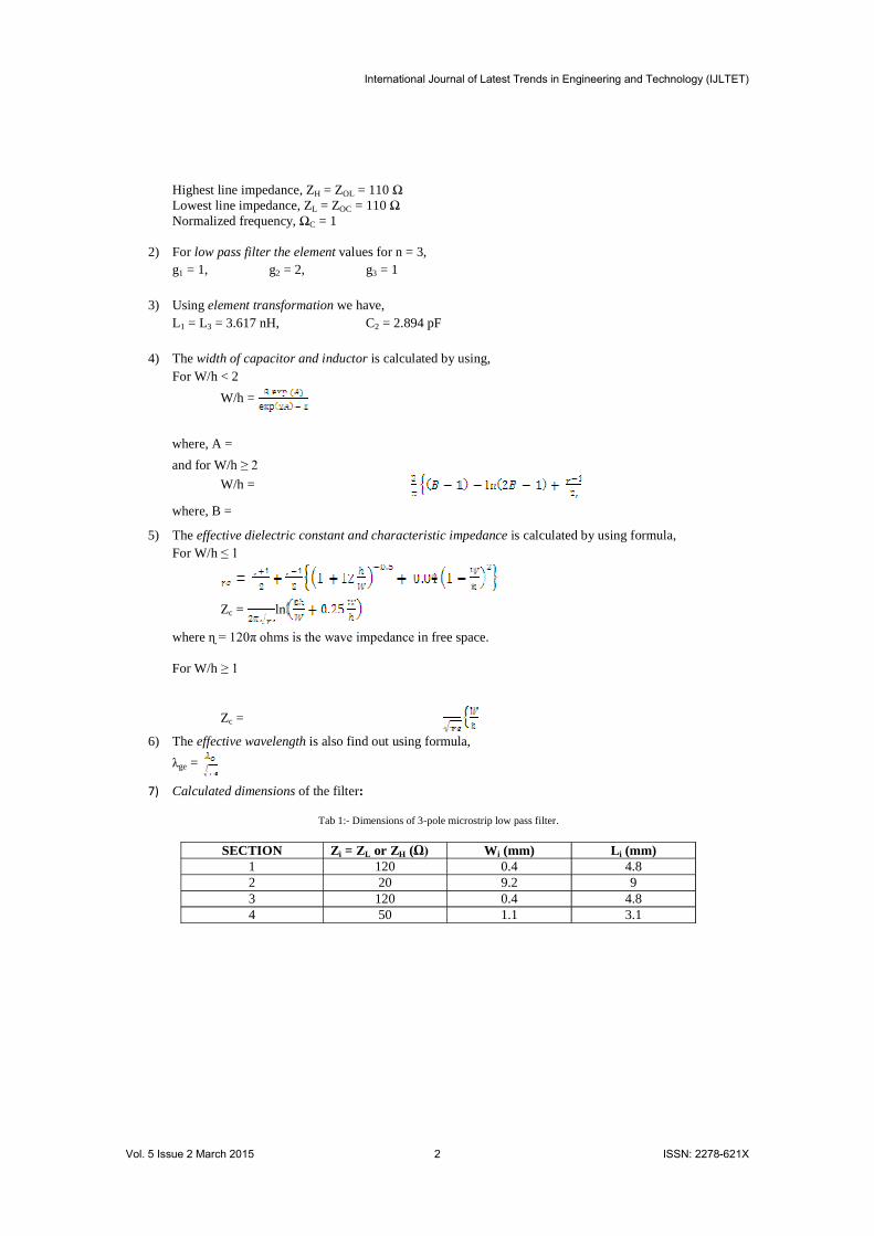
Highest line impedance, ZH = ZOL = 110 Lowest line impedance, ZL = ZOC = 110 Normalized frequency, C = 1
2) For low pass filter the element values for n = 3, g1 = 1, g2 = 2, g3 = 1
3) Using element transformation we have, L1 = L3 = 3.617 nH, C2 = 2.894 pF
4) The width of capacitor and inductor is calculated by using, For W/h < 2
W/h =
where, A =
and for W/h W/h =
where, B =
5) The effective dielectric constant and characteristic impedance is calculated by using formula, For W/h
Zc = ln
where n free space.
For W/h
Zc =
6) The effective wavelength is also find out using formula,
ge =
7) Calculated dimensions of the filter:
Tab 1:- Dimensions of 3-pole microstrip low pass filter.
SECTION Zi = ZL or ZH ( Wi (mm) Li (mm) 1 120 0.4 4.8 2 20 9.2 9 3 120 0.4 4.8 4 50 1.1 3.1
International Journal of Latest Trends in Engineering and Technology (IJLTET)
Vol. 5 Issue 2 March 2015 2 ISSN: 2278-621X
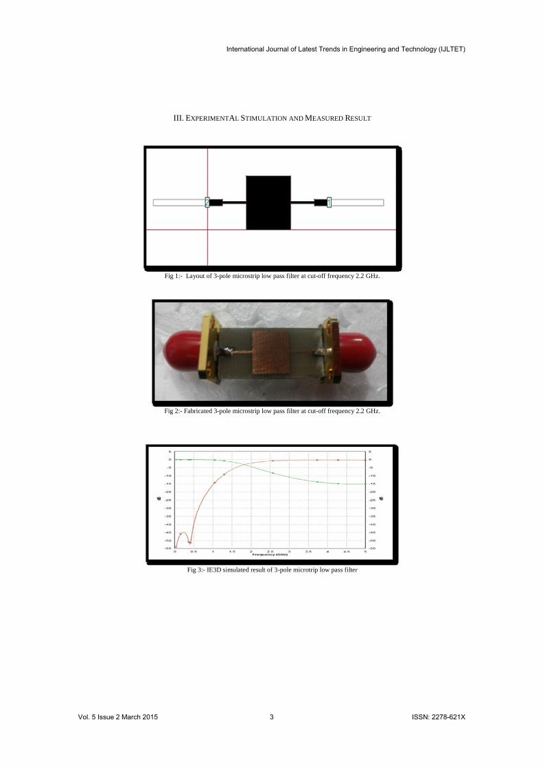
III. EXPERIMENTAL STIMULATION AND MEASURED RESULT
Fig 1:- Layout of 3-pole microstrip low pass filter at cut-off frequency 2.2 GHz.
Fig 2:- Fabricated 3-pole microstrip low pass filter at cut-off frequency 2.2 GHz.
Fig 3:- IE3D simulated result of 3-pole microtrip low pass filter
International Journal of Latest Trends in Engineering and Technology (IJLTET)
Vol. 5 Issue 2 March 2015 3 ISSN: 2278-621X
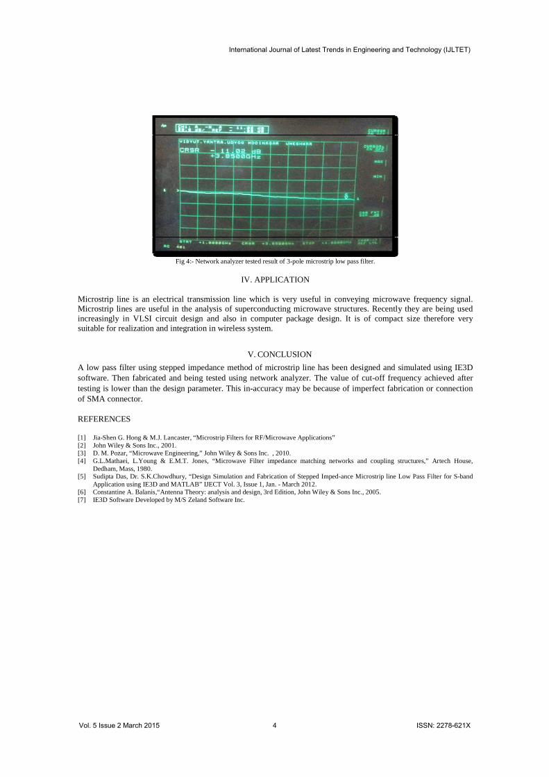
Fig 4:- Network analyzer tested result of 3-pole microstrip low pass filter.
IV. APPLICATION
Microstrip line is an electrical transmission line which is very useful in conveying microwave frequency signal. Microstrip lines are useful in the analysis of superconducting microwave structures. Recently they are being used increasingly in VLSI circuit design and also in computer package design. It is of compact size therefore very suitable for realization and integration in wireless system.
V. CONCLUSION
A low pass filter using stepped impedance method of microstrip line has been designed and simulated using IE3D software. Then fabricated and being tested using network analyzer. The value of cut-off frequency achieved after testing is lower than the design parameter. This in-accuracy may be because of imperfect fabrication or connection of SMA connector.
REFERENCES
[1] Jia-Shen G. Hong & M.J. Lancaster, “Microstrip Filters for RF/Microwave Applications” [2] John Wiley & Sons Inc., 2001. [3] D. M. Pozar, “Microwave Engineering,” John Wiley & Sons Inc. , 2010. [4] G.L.Mathaei, L.Young & E.M.T. Jones, “Microwave Filter impedance matching networks and coupling structures,” Artech House,
Dedham, Mass, 1980. [5] Sudipta Das, Dr. S.K.Chowdhury, “Design Simulation and Fabrication of Stepped Imped-ance Microstrip line Low Pass Filter for S-band
Application using IE3D and MATLAB” IJECT Vol. 3, Issue 1, Jan. - March 2012. [6] Constantine A. Balanis,“Antenna Theory: analysis and design, 3rd Edition, John Wiley & Sons Inc., 2005. [7] IE3D Software Developed by M/S Zeland Software Inc.
International Journal of Latest Trends in Engineering and Technology (IJLTET)
Vol. 5 Issue 2 March 2015 4 ISSN: 2278-621X