Embed Size (px)
Citation preview

American-Eurasian Journal of Scientific Research 11 (5): 361-380, 2016ISSN 1818-6785© IDOSI Publications, 2016DOI: 10.5829/idosi.aejsr.2016.11.5.22955
Corresponding Author: Sathishkumar Shanmugam, Jansons institute of Technology, Coimbatore, India.
361
Design and Implementation of Low Cost Four Switch Inverter forBrushless Motor Drive with Active Power Factor Correction
Sathishkumar Shanmugam, Surya Meyporul, Aruna Subramanian,1 1 1
Parimal Krishnan and Meenakumari Ramachandran1 2
Jansons institute of Technology, Coimbatore, India1
Kongu Engineering, India2
Abstract: This Research paper proposes a low cost four switch three phase inverter (FSTPI) fed brushless DC(BLDC) motor drive for Active power factor correction for residential applications without environmental issues.This proposed system is simplified the topological structure of the conventional six switch three phase inverter(SSTPI) and includes an active power factor correction in front end rectifier which results in sinusoidal inputcurrent and it closed to unity power factor. In this project a new structure of four switch three phase inverterwith reduced number of switches for system is introduced. This system consists of single phase rectifier andfour switch three phase inverter. This proposed inverter fed BLDC motor used in Sensorless control schemes.To improve sensorless control performance, six commutation modes based on direct current controlled PWMscheme is implemented to produced the desire Torque-Speed characteristics. This four switch three phaseinverter is achieved by the reduction of switches, low cost control and saving of hall sensor. The design andimplementation of low cost four switch inverter for Brushless motor drive with active power factor correctionhave been conducted successfully and valediction of the proposed sesorless control for four switch threephase inverter fed BLDC motor drive is developed and analysed using both MATLAB/SIMULINK andhardware results are verified out successfully.
Key words: BLDC Motor Power Factor Correction Four Switch Three Phase Inverter (FSTPI) Sensorlesscontrol Direct current control
INTRODUCTION employing a pulse width modulation (PWM) are being
The Permanent Magnet Brushless DC (PMBLDC) industrial applications. However, cost minimization can be(without pollution and vibration) motor is gaining achieved by reduction of the inverter configurationpopularity being used in computer, aerospace, military, employing a topological approach and control approach.automotive, industrial and household products because In the topological approach, minimum number of switchesof its high torque, compactness and high efficiency. is required in inverter circuit. From the control approachThe Brushless DC (BLDC) motor is inherently point of view control algorithms are designing andelectronically controlled and requires rotor position implementing for inverter to produce the desiredinformation for proper commutations of current. The speed-torque characteristics. Among the implements, theBLDC motor has advantages of the DC motor such as three phase inverters have only four switches, the mainsimple control, high torque, high efficiency and features of these inverter are reduction of switches andcompactness. Also, brush maintenance is no longer conduction losses. Until now, reduced components haverequired and many problems resulting from mechanical been applied in AC induction motor drives, however nowwear of brushes and commentators are improved by a day the BLDC motor drives are using due to its highchanging the position of rotor and stator in DC motor. power factor, high torque, simple control and lowerVariable speed inverter fed AC motor drives are maintenance. The four switches three phase inverter
used for various purposes in consumer products and

Am-Euras. J. Sci. Res., 11 (5): 361-380, 2016
362
Fig. 1: Block Diagram of Proposed Research
(FSTPI) used in six commutation modes based on current the inverter, while the third phase ‘c’ is connected tocontrol and senseless control schemes. In these BLDC the centre point of the dc- link capacitors, C1 and C2.drive configuration, it employs a single-phase to three A regulator circuit removes the ripples and also remainsphase converter using only six IGBT switches shown in the same dc value even if the input dc voltage varies, orFigure 1. This converter has been already employed in the load connected to the output dc voltage changes.variable-speed induction motor drives. This configuration The pulse generator is used to generating the triggeringincludes a half bridge active rectifier structure at front end pulse and given to the driver circuit. The driver circuit isthat provides the Dc link with an active input current used to amplify the triggering pulse and given to the DCshaping feature. Moreover, the front end rectifier allows to AC converter. A BLDC has a rotor with permanentbidirectional power flows between the DC link and the Ac magnets and a stator with windings, which are connectedsupply. Since the MOSFET switches can operate at high to the control electronics. The control electronics replacefrequency, advance PWM techniques for inverter control the function of the commutator and energize the propercan be used. Therefore, the proposed converter can be winding The FSTPI is converting the DC to AC. It iscontrolled to draw sinusoidal input current at power factor working PWM control strategy in using the hysteresisclose to unity and to simultaneously deliver high-quality current control. The triggering units provide the requiredoutput current to the motor [1]. pulses to the power MOSFET.The values of each block
MATERIALS AND METHODS The generated codes are loaded to the PIC
Figure 1 shows block diagram of proposed processor through the ADC. The generated error signal isResearch system. The block diagram mainly consist of a fed to the PI controller in the processor. Based on thePIC-microcontroller (PIC16F877) for power factor output of PI controller, the processor generated thecalculation, FSTP Inverter, driver circuit, opto-isolator, required controlled pulses for FSTPI to control the speedzero crossing detection, low pass filter and BLDC motor. of the BLDC motor [2].The ac voltage, typically 230V is connected to atransformer, which steps that ac voltage down the supply Objective of the Research: In modern electrical machinesvoltage (0-230V) to (0-6V) to the level of the desired dc industry productions the brushless direct current (BLDC)output. The single phase AC supply is fed to rectifier to motors are rapidly gaining popularity. BLDC motors areobtain DC voltage; this DC voltage is provided with a used in industries such as Appliances, HVAC industry,capacitor filter. The FSTPI outputs phases are a, b, c. medical, electric traction, road vehicles, aircrafts, militaryTwo phases ‘a’ and ‘b’ are connected to the two legs of equipment, hard disk drive.
are adjusted according to the need of drive system.
microcontroller. The sensor less output is fed to the

Am-Euras. J. Sci. Res., 11 (5): 361-380, 2016
363
Fig. 2: Circuit Diagram of Proposed Research FSTPI for AC (i.e. vector control) or it can be optimized for DCSystem without natural defects (i.e. block commutation). A motor which is optimized for
Motivated by these observations, the objective of EMF. One can easily observe the shape of the EMF bythis Research is: connecting the motor wires (at least two of them) to an
Modeling and analysis of the PMBLDC motor shaft.PMBLDC motors are a type of synchronous motor.FSTPI fed BLDC motor drive system is implemented This means the magnetic field generated by the stator andthrough prototype model the magnetic fields generated by the rotor rotate at theDirect current controlling of the PMBLDC motor same frequency. PMBLDC motors do not experience theusing PI controller “slip” that is normally seen in induction motors. PMBLDC
Permanent Magnet Brushless DC Motor: Permanent configurations. Corresponding to its type, the stator hasmagnet Brushless Direct Current (PMBLDC) motors are the same number of windings. Out of these, 3-phaseone of the motor types rapidly gaining popularity. motors are the most popular and widely used. ThisPMBLDC motors are used in industries such as application notefocuses on 3-phase motors. The stator ofAppliances, Automotive, Aerospace, Consumer, Medical, a BLDC motor consists of stacked steel laminations withIndustrial Automation Equipment and Instrumentation. windings placed in the slots that are axially cut along theAs the name implies, BLDC motors do not use brushes for inner periphery Traditionally, the stator resembles that ofcommutation; instead, they are electronically commutated. an induction motor; however, the windings are distributedBLDC motors have many advantages over brushed DC in a different manner [4].motors and induction motors. A few of these are Better Most BLDC motors have three stator windingsspeed versus torque characteristics, High dynamic connected in star fashion. Each of these windings isresponse , High efficiency, Long operating life, Noiseless constructed with numerous coils interconnected to formoperation , Higher speed ranges .In addition, the ratio of a winding. One or more coils are placed in the slots andtorque delivered to the size of the motor is higher, making they are interconnected to make a winding. Each of theseit useful in applications where space and weight are windings is distributed over the stator periphery to formcritical factors [3]. an even numbers of poles as shown in Figure 3. There are
AC and DC Power Supplies sinusoidal motors. This differentiation is made on theDirect Current (DC) Motor: DC applied to both the stator basis of the interconnection of coils in the stator windingsand the rotor (via brushes and commutator), or else a to give the different types of back Electromotive Forcepermanent magnet stator. A BLDC motor has switched DC (EMF). The stator of a BLDC motor consists of stackedfed to the stator and a permanent magnet rotor. steel laminations with windings placed in the slots that areSynchronous (or stepping) motor (AC): AC in one, DC in axially cut along the inner periphery as shown in Figure 4.the other (i.e., rotor or stator). If it has a permanent- Traditionally, the stator resembles that of an inductionmagnet rotor, it is much like a BLDC motor. Induction motor; however, the windings are in a different manner.motor (AC): AC in both stator and rotor (mentioned for Most BLDC motors have three stator windings connectedcompleteness). Although BLDC motors are practically in star fashion. Each of these windings is constructedidentical to permanent magnet AC motors, the controller with numerous coils interconnected to form a winding.
implementation is what makes them DC. While AC motorsfeed sinusoidal current simultaneously to each of the legs(with an equal phase distribution), DC controllers onlyapproximate this by feeding full positive and negativevoltage to two of the legs at a time. The major advantageof this is that both the logic controllers and battery powersources also operate on DC, such as in computers andelectric cars. In addition, the approximated sine waveleaves one leg driven at all times, allowing for back-EMF-based sensorless feedback. A motor can be optimized
block commutation will typically generate trapezoidal
oscilloscope and then hand-cranking/spinning the
motors come in single-phase, 2-phase and 3-phase
two types of stator windings variants: trapezoidal and

Am-Euras. J. Sci. Res., 11 (5): 361-380, 2016
364
Fig. 3: Three Phase Three Coil BLDC Motor Stator and Rotor
Fig. 4: Rotor of a PMBLDC Motor
One or more coils are placed in the slots and they are such as poor power factor (PF), increased total harmonicinterconnected to make a winding. Each of these windings distortion (THD) of current at input AC mains It is mainlyis distributed over the stator periphery to form an even due to uncontrolled charging of the DC link capacitornumbers of poles. The rotor is made of permanent magnet which results in a pulsed current waveform having a peakand can vary from two to eight pole pairs with alternate value higher than the amplitude of the fundamental inputNorth (N) and South (S) poles. Based on the required current at AC mains [5].magnetic field density in the rotor, the proper magneticmaterial is chosen to make the rotor. Ferrite magnets are Mathematical Modelling: Brushless DC Motors are pertraditionally used to make permanent magnets. As the magnet motors where the function of commutator andtechnology advances, rare earth alloy magnets are gaining brushes were implemented by solid state switches. BLDCpopularity. The ferrite magnets are less expensive but motors come in single- phase, 2-phase and 3-phasethey have the disadvantage of low flux density for a given configurations. Corresponding to its type, the stator hasvolume. In contrast, the alloy material has high magnetic the same number of windings. Out of these, 3-phasedensity per volume and enables the rotor to compress motors are the most popular and widely used. Because offurther for the same torque. Also, these alloy magnets the special structure of the motor, it produces aimprove the size-to-weight ratio and give higher torque for trapezoidal back electromotive force (EMF) and motorthe same size motor using ferrite magnets. current generate a pulsating torque.
A PMBLDC which is a kind of three-phase A three phase BLDC motor equation can besynchronous motor with permanent magnets (PMs) on represented as:the rotor and trapezoidal back EMF waveform operates onelectronic commutation accomplished by solid state (2.1)switches using PWM technique. It is powered through athree-phase voltage source inverter (VSI) which is fedfrom single-phase AC supply using a half bridge rectifier (2.2)followed by smoothening DC link capacitor. ThePMBLDCM drive, fed from a single-phase AC mainsthrough a halfbridge rectifier followed by a DC link (2.3)capacitor, suffers from power quality (PQ) disturbances

Am-Euras. J. Sci. Res., 11 (5): 361-380, 2016
365
where, factorsAngular velocity of the rotor , Magnetic fieldR- Stator resistance per phase. generated by rotor magnets , The number of turns in theL- Stator inductance per phase stator windings. The three phase currents are controlledM- Mutual inductance between the phases. to take a quasi-square waveform in order to synchronizei , i , i - Stator current per phase. with the trapezoidal back EMF to produce the constanta b c
v , v , v - are the respective phase voltage of the winding. torque.a b c
The stator self inductances are independent of the The instantaneous back EMF in BLDC is written as:rotor position, hence:
L =L =L =L (2.4)a b c
And the mutual inductances will have the form:
M =M =M =M =M =M =M (2.5) The respective back EMF in the windings isab ac ba bc ca cb
Assuming three phase balanced system, all the phaseresistances are equal:
R =R =R =R (2.6) (2.16)a b c
Rearranging the above equations:
(2.7)
(2.8)
(2.9) (2.17)
Neglecting mutual inductance:
(2.10) theoretical motor constant K the supplied current. In a
(2.11) rotation of the stator, additional coils, or “phases” are
(2.12) current I.
When a BLDC motor rotates, each winding generatesa voltage known as back Electromotive Force or back T +T +T (2.19)EMF, which opposes the main voltage supplied to thewindings according to Lenz s Law. The polarity of this Assumption made is all the phases are perfect symmetryback EMF is in opposite direction of the energizedvoltage. Back EMF depends mainly on three Kt(motor)= Kt(a)+Kt(b)+Kt(c) (2.20)
e = f ( )K (2.13)a a e
e = f ( )K (2.14)b b e
e = f ( )K (2.15)c c e
represented by the below equation.
(2.16)
Torque Generation: The Torque is the product of thet
single pole system, usable torque is only produced for 1/3of the rotation. Toproduce useful torque throughout the
added to the fixed stator. The developed torque by eachphase is the product of the motor constant K andt
The sum of the torques is:
a b c

( ) *2d P
dt =
RF APP P=
Am-Euras. J. Sci. Res., 11 (5): 361-380, 2016
366
At any given angle, the applied torque as measured to a rectifier with a 3-wire input from a transformer with aon the rotor shaft is (2.23). The key to effective torque and center-tapped secondary winding. The essential featurespeed control of a BLDC motor is based on relatively of a diode bridge is that the polarity of the output is thesimple torque and back EMF equations [6, 7], which are same regardless of the polarity at the input.similar to those of the DCmotor. The generatedelectromagnetic torque is given by: Power Factor Correction: Many loads are highly
T = [e i + e i + e i ]/ (2.21) transformers and ballasts. You may want to correct thee a a b b c c
The electromagnetic torque is also related with motor add series capacitors to "remove" the effect of leakageconstant and the product of the current with the electrical inductance that limits the output current. The current flowrotor position which is given as: through the circuit is increased by thereactive component.
T = K {f ( )i + f ( )i + f ( )i } (2.22) of a resistance and a purely imaginary reactance. For thise t a a b b c c
The equation of motion for simple system is, parallel combination. The diagram below illustrates a
J /dt + B = T – T (2.23) some finite resistance in the conductors, etc.A figure ofde l
where T is the load torque, J is motor inertia, B is damping apparent power is the power factor of the Converter (P ):coefficient. For a BLDC motor which its magnet length is180 electrical degrees, the ideal phase currents to produce (3.1)a relative smooth torque pulsation are rectangularwaveforms with 120 degree phase differences.. Since the The power factor is maximized at unity when the realproduced torque is linearly proportional to one of the power and apparent power are equal.phase current at each time, torque can be achieved by a The benefits in maximizing PF are summarizedMoredirect current control. The relation between angular power can be delivered through the Converter to thevelocity and angular position (electrical) is given by; loads at the same AC outlet rating.
(2.24) Output power = V I PF (3.2)
where, where, e = Efficiency of the Converter.P is numbers of Poles
Single Phase Rectifier: A rectifier changes alternating power for PF of unity. In three phase with neutral ACcurrent into direct current. This process is called supply configuration, lowering the harmonic content ofrectification. The three main types of rectifier are the half- the AC current in each phase reduces the harmonicwave, full-wave and bridge. A rectifier is the opposite of current that must be carried by the neutral conductor.an inverter, which changes direct current into alternating Reducing the harmonic losses of the Utility line reactivecurrent.The first building block in the dc power supply is elements such as Transformers, Motors, Capacitors andthe half wave rectifier. The purpose of the half wave Reactors. Reduce conducted and radiated electronic noiserectifier is to create a rectified ac output from a sinusoidal pollution. To derive maximum power factor it is necessaryac input signal. It does this by using the nonlinear to correct the distorted current. Methods to "shape" theconductivity characteristics of IGBT to direct the path of current waveform can be categorized into passive Powerthe current. When used in its most common application, Factor Correction (PFC) and active Power Factorfor conversion of an alternating current (AC) input into Correction. As the name implies, passive PFC usesdirect current (DC) output, it is known as rectifier [8]. A passive elements in networks which the current waveformrectifier provides half-wave rectification from a two-wire is "shaped" or filtered to remove the unwanted harmonics.AC input, resulting in lower cost and weight as compared The passive PFC networks can be very effective in
inductive, such a lightly loaded motors and illumination
power factor by adding parallel capacitors. You can also
Normally, loads are represented by a series combination
explanation, it is easier to contemplate it as an equivalent
partially reactive load being fed from a real system with
merit using the relative ratio of the real power over theF
rms rms
The available outlet power is maximized for output

Am-Euras. J. Sci. Res., 11 (5): 361-380, 2016
367
increasing the PF of the capacitive input filter converters. Active Power Factor Correction: Besides using passiveHowever these passive PFC networks must operate at the networks, active power conversion circuits can beAC line frequency which dictates the bulky physical size employed as PF correction converters. Passive PFandweight of the passive elements. This disadvantage correction networks filter and shape the current waveformmust be balanced against the appeal of the relative to remove the unwanted harmonics. The active PFCsimplicity of the passive PFC networks. An alternative to converters accomplish the same by modulating thepassive PFC networks is to use active circuits to reshape current extracted from the power line at the switchingthe current waveform. The active circuit consist of a frequency of the converter. The converter is placedpower converter operating at frequencies several orders between the capacitive input filter and the power line toof magnitude higher than the AC line frequency. The shape the line current into a more desirable waveform.physical size and weight of the reactive elements used in Compared to the passive PFC networks, the PFC [6-14]the active PFC converter is much reduced compared to its converter can achieve the same or higher PF with muchcounter parts in the passive PFC networks. The active lower inductance value. The consequence of highPFC converter can also achieve near unity PF with very frequency input current modulation effectively multipliesreasonable reactive element values. the actual inductor value in the convertor reflected into
Passive Power Factor Correction: Passive power factor rectified by the front-end switches T1 and T2. Thecorrection networks employs passive filters to "shape" or switches T1 and T2 are operated based on a PWMfilter the input line current. Two popular passive PF strategy to regulate the DC link voltage and shape thecorrection filter networks areInductive Input Filter, input current to be sinusoidal with either in phase(inResonant Input Filter.The governing equations and normal mode) or 180 degree out of phase(in regenerationmaximum achievable power factor for each network are mode) the AC input voltage.implemented.The inductive input filter, depicted, differwith the capacitor input filter by an additional inductor. Four Switch Three Phase Inverter (FSTPI): TheThe sinusoidal line source and the full bridge connected Modelling of the four switch three phase BLDC motorrectifiers are replaced by an equivalent absolute value drive system is based on some assumptions [3]. All thesinusoidal source for analysis. Unlike the capacitor input stator phase windings have equal resistance per phasefilter, where the capacitor voltage charges to the peak and constant self and mutual inductances Poweramplitude of the input voltage, the inductor input filter semiconductor devices are ideal, Iron losses are negligibleaverages the full wave rectified voltage over a period that and the motor is unsaturated. It contains two capacitorsis half the period of the line source .The extent of PF instead of two switches and the phase c is out of controlcorrection achieved by the inductive input filter is a because it is connected to the midpoint of the seriesfunction of the inductor value, L and the output load of capacitor. The phase c voltage cannot hold at zero, itthe filter, R.The inductor serves as the energy storage makes distortion in other phases. The same problem iselement filling in the discontinuous sections of the current inherited by the four–switch mode and it causes thepulses and resulting in a more continuous waveform. produced voltage vectors to be limited and asymmetric,However, the inductive input filter cannot produce unity which were well known as asymmetric voltage vectors.power factor since the inductor current will never become The operation of four switch BLDC motor contains sixan in phase sinusoidal waveform. This can be explained modes of operation [15].by considering an infinite inductor as a constant current With respect to the circuit of figure5 the FSTPIsource regardless the amplitude of the input voltage. circuit consists of S1, S2, S3 and S4 four IGBT switchesTherefore even with an infinite inductance the current and split capacitors C1 and C2. The single phase ACwaveform will not be related to the applied voltage by a supply is fed to rectifier to obtain DC voltage; this DCscalar constant.When the resonant frequency of the filter voltage is provided with a capacitor filter. The FSTPIis tuned to the line frequency, only line frequency current outputs phases area, b, c. Two phases ‘a’ and ‘b’ arecomponent is allowed to pass through the filter. For the connected to the two legs of the inverter, while the thirdideal case ofzero DC resistance, the input current can be phase ‘c’ is connected to the centre point of the dc- linkshaped into a sinusoidal waveform and resulting in power capacitors, C1 and C2. The four power switches arefactor of unity. denoted by the binary variables S1 to S4, where the binary
the AC line. The single phase fixed frequency AC input is

Am-Euras. J. Sci. Res., 11 (5): 361-380, 2016
368
Fig. 5: Circuit Diagram of FSTPI fed BLDC Motor
‘1’ corresponds to an ON state and the binary ‘0’ Therefore, BLDC sensorlesscontrol[5] has been receivingcorresponds to an OFF state. The states of the upper great interest in recent years. Typically, BLDC motors areswitches (S1, S2) and lower switches (S3, S4) of a leg fed by a four switch three-phase inverter (FSTPI) with,are complementary that is S3 =1- S1 and S4 =1- S2. what is called, electric commutation. The commutationThe terminal voltages Vas, Vbs and Vcs of a 3-phase interval for each step is 60 degrees by electrical angle.Y-connected Induction Motor can be expressed as the It is determined by the rotor position, which can befunction of the states of the upper switches.Since, there detected by estimated hall signals from the back EMF zerois no control on the third phase, the middle point of the crossing. Of course, there are many other sensorlessDC link (point C) is taken as the reference, so: techniques [6], these techniques require more complex
(3.3) limitation in the applications. As three-phase BLDC
(3.4) degree [7]. Therefore, the Back-EMF zero-crossing
(3.5) source at one time instant so the third phase can be
where Vas, Vbs, Vcs are the inverter output voltages, the source, phase W is floating. No current is goingVc is the voltage across the dc link capacitors, Vdc is through this phase. This conducting interval lasts 60the voltage across the capacitors C1 and C2 (Vc =V dc / electrical degrees, which is called commutation step.2). In matrix form the above equations can be written as: This is described by the following conditionsIn these
[ ] / ( ) [ ] / [ ] diode is ignored for simplification. So if you compare
(3.6) zero-crossing point of back EMF voltages. But the
Control Techniques Low Pass Filter (LPF) circuitare used to eliminate theSensorless Control Scheme: In case of BLDC drive harmonic components. And then you can detect thesystem utilizing hall sensors, hall sensor circuit and zero-crossing point with internal comparators. When acontrol are simple but these will increase the cost and the zero crossing is detected, several calculations start.size of the motor. In some applications like as a The next commutation time is calculated by computationscompressor application for air conditioner, it may not be of the actual speed. The speed command is set accordingacceptable to mount any hall sensors on the stator. to the state of the run/stop state and the target speed
calculation than the back EMF method, so there are some
motor is driven with six-step 120 degree control method.That means the conduction interval of one phase is 120
detecting technique is based on the fact that onlytwophases of a BLDC motor are connected to the power
used to detect zero-crossing of the Back-EMF voltage.For example, when phase U and phase V are connected to
equations, forward voltage drop of MOSFET and body
terminal voltages (Va, Vb and Vc) with a reference voltageby using 3 comparators, then you can detect the
terminal voltages contain many harmonic componentswith several times of PWM switching frequency. So the

Am-Euras. J. Sci. Res., 11 (5): 361-380, 2016
369
from user. The applied voltage and back-EMF are the magnetization of the core and because of drops in thebalanced so that the torque necessary to maintain rotor primary and secondary windings due to leakage reactancespeed is achieved.For a BLDC motor to generate maximum and winding resistance. One can thus talk of a voltageand constant output torque, their phase currents should error, which is the amount by which the voltage is lessbe rectangular with 120° conducting and 60° non- than the applied primary voltage and the phase error,conducting intervals. Also at each operating mode, only which is the phase angle by which the reversedtwo phases are conducting and the other phase remains secondary voltage vector is displaced from the primarysilent. However, in the four-switch converter based on the voltage.four switching vectors, the generation of 120° conductingand a 60° non-conducting current profiles is inherently Power Circuit of Microcontroller: Power supply is adifficult. That means the conventional PWM schemes reference to a source of electrical power. A device oremployed for four switch induction motor drives cannot system that supplies electrical or other types of energy tobe directly applied to BLDC motor drives. This led to the an output load or group of loads is called a power supplydevelopment of a new control scheme called Direct unit or PSU. The term is most commonly applied toCurrent Controlled PWM scheme. electrical energy supplies, less often to mechanical ones
Hardware Unit The operation of power supply circuits built usingVoltage & Current Measurement Unit: This unit filters, rectifiers and then voltage regulators. Starting withcontains components for measuring the line current and an AC voltage, a steady DC voltage is obtained byvoltage in order to calculate the power factor, It consists rectifying the AC voltage, then filtering to a DC level andof Current transformer, Potential transformer. A current finally, regulating to obtain a desired fixed DC voltage.transformer is a type of "instrument transformer" that is The regulation is usually obtained from an IC voltagedesigned to provide a current in its secondary which is regulator Unit, which takes a DC voltage and provides aaccurately proportional to the current flowing in its somewhat lower DC voltage, which remains the same evenprimary. Current transformers are designed to produce if the input DC voltage varies, or the output Loadeither an alternating current or alternating voltage connected to the DC voltage changes [15].proportional to the current being measured. currenttransformers measure power flow and provide electrical Rectifier and Inverter: In this proposed system, singleinputs to power transformers and instruments. Current phase to three phase converter using only six MOSFETtransformers produce either an alternating current or (IRFZ48N) switches. This configuration includes a halfalternating voltage that is proportional to the measured bridge rectifier (at the front end) and FSTPI [10]. The halfcurrent. There are two basic types of current transformers: bridge rectifier provides the DC link with an active inputwound and toroidal. Wound current transformers consist current shaping. Moreover, the front end rectifier allowsof an integral primary winding that is inserted in series bidirectional power flows between DC link and the ACwith the conductor that carries the measured current. supply. The FSTPI consists of four switches andToroidal or donut-shaped current transformers do not capacitors [11]. Two phases (A & B) are connected to thecontain a primary winding. Instead, the wire that carries two legs of the inverter, while the third phase C isthe current is threaded through a window in the connected to the center point of the DC-link capacitors C1toroidaltransformer.The standards define a voltage and C2 are shown in Figure 7 & 8 & 9 [12, 13].transformer as one in which "the secondary voltage issubstantially proportional to the primary voltage and Optoisolator: There are many situations where signalsdiffers in phase from it by an angle which is approximately and data need to be transferred from one subsystem tozero for an appropriate direction of the connections. It another within a piece of electronics equipment, or frommeans that the voltage transformer has to be as close as one piece of equipment to another, without making apossible to the "ideal" transformer. In an "ideal" direct ohmic electrical connection. Often this is becausetransformer, the secondary voltage vector is exactly the source and destination are (or may be at times) at veryopposite and equal to the primary voltage vector, when different voltage levels, like a microprocessor, which ismultiplied by the turn’s ratio. In a "practical" transformer, operating from 5V DC but being used to control a triacerrors are introduced because some current is drawn for that is switching 240V AC. In such situations the link
and rarely to others are shown in Figure 6.

Am-Euras. J. Sci. Res., 11 (5): 361-380, 2016
370
Fig. 6: Power Circuit of Microcontroller
Fig. 7: Equivalent Circuit of FSTPT fed BLDC Motor
between the two must be an isolated one, to protect the combination of two distinct devices: an opticalmicroprocessor from over voltage damage. Suppose transmitter, typically a gallium arsenide LED (light-control circuit is connected to power circuit without emitting diode) and an optical receiver such as aisolation circuit the control circuit may get affect so phototransistor or light-triggered diac. The two areneeded to isolation circuit interface between power separated by a transparent barrier which blocks anycircuit and control circuit.Relays can of course provide electricalcurrent flow between the two, but does allow thethis kind of isolation, but even small relays tend to be passage of light. The basic idea is shown, along with thefairly bulky compared with ICs and many of today’s usual circuit symbol for an optoisolator.The 6N135other miniature circuit components.Because they’re optoisolator consists of a light-emitting diode and anelectro-mechanical, relays are also not as reliable and integrated photon detector composed of a photodiodeonly capable of relatively low speed operation. Where and an open-collector output transistor. Separatesmall size, higher speed and greater reliability are connections are provided for the photodiode bias and theimportant, a much better alternative is to use an transistor-collector output.optoisolator. These use a beam of light to transmit thesignals or data across an electrical barrier and achieve Zero Crossing Detection Circuit: As the name indicatesexcellent isolation.Optoisolator typically come in a small the zero crossing detector is a device for detecting the6-pin or 8-pin IC package, but are essentially a point where the voltage crosses zero in either direction.

Am-Euras. J. Sci. Res., 11 (5): 361-380, 2016
371
Driver Circuit
Fig. 8: Gate Drive Circuit of Proposed FSTPI System
Fig. 9: Power Circuit of Driver Unit
As shown in the Figure 9 the first section is a FSTPI, square wave converter. Anyone of the inverting orwhich provides three phase voltages. This is applied to non-inverting comparators can be used as a zero-crossingthe op- amp comparator circuit. The zero crossing detector detector. The only change to be brought in is thecircuit is an important application of the op-amp reference voltage with which the input voltage is to becomparator circuit. It can also be called as the sine to compared, must be made zero (Vref = 0V).

Am-Euras. J. Sci. Res., 11 (5): 361-380, 2016
372
Fig. 10: Zero Crossing Detection Circuit
An input sine wave is given as Vin. These are shown PIC 16F877A Microcontroller Used in Research: Thein Figure 10 and input and output waveforms of an PIC 16F877A Microcontroller is the prime controller of thisinverting comparator with a 0V reference voltage. The project. It controls the operation of various circuitsoutput of the op-amp comparator is applied to the base of associated in this project. The PIC 16F877the transistor through a base resistor, R7. This charge is Amicrocontroller issues control signal to the MOSFETavailable to the transistor as VCC. The transistor remains drive circuit [9]. The various features present in thisOFF until the Cut-in voltage VBE is reached. During the PIC16F877A helps to achieve an effective control over theOFF period of the transistor the output will be high and induction motor are shown in Figure 11.approximately equal to VCC.A zero crossing detectorliterally detects the transition of a signal waveform from BLDC Motor: A 1000 KV and 12 V Brushless outrunnerpositive and negative, ideally providing a narrow pulse motor is used for proposed FSTPI system. Are shown inthat coincides exactly with the zero voltage condition. Table 1.

Am-Euras. J. Sci. Res., 11 (5): 361-380, 2016
373
Fig. 11: PIC16F877A Microcontroller
Table 1: BLDC Motor SpecificationsVariable name ValueNumber of poles 4Number of slots 4Rated Speed 1000 rpmMaximum efficiency 80%Current capacity 12 A/ 60 SNumber of cells 2-3 Li-Poly
RESULTS AND DISCUSSION
Simulation and Experimental Results of FSTPI System:Power Supply Unit: Figure 12 shows the supply to thePIC16F877A microcontroller. From the result, it is foundthat the power supply unit provides voltage of about 5 Vto the PIC microcontroller unit.
Figure 13 shows the power supply to the driver unit.From the result, it is found that the power supply unitprovides voltage of about 15 V to the driver unit.
Gate Pulse Generation of Proposed FSTPI System:Figure 14 and Figure 15 shows the pulses to the switchesS1, S2 of front end rectifier respectively. Experimentally,results are attained with pulses each of about 15 V.
Figure 16 to Figure 19 shows the gate pulses to theswitches S3 to S6 of FSTP inverter respectively.
Experimentally, results are attained with pulses each ofabout 15 V.
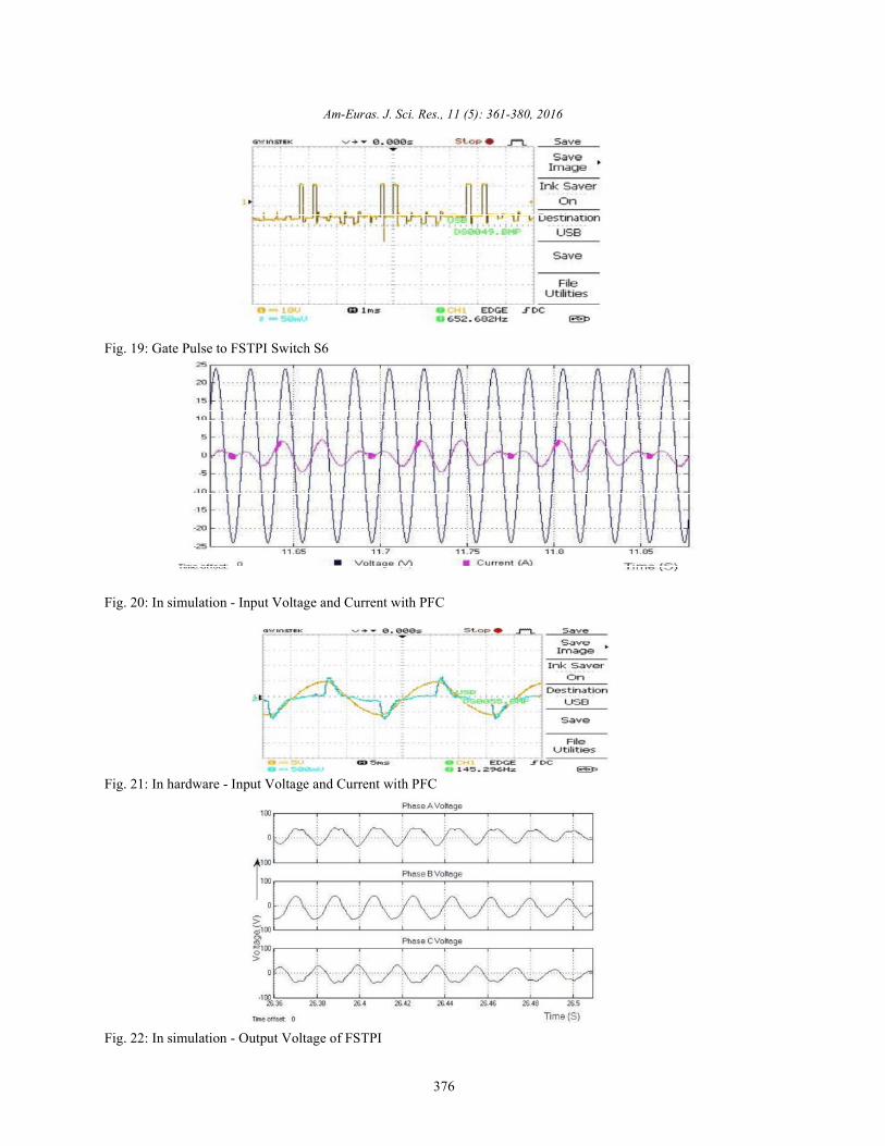
FSTPI System with BLDC Motor: Figure 20 and Figure21 shows the simulation and experimental results ofsupply voltage and current of the proposed FSTPI systemwith PFC respectively. This proposed converter drawsnear sinusoidal current with power factor close to unity[15].
Advantages of Power Factor Correction: The mainadvantages of the Power Factor Correction are, Theelectrical load on the Utility is reduced, thereby allowingthe Utility to supply the surplus power to otherconsumers, without increasing its generation capacity [1].Most of the Utilities impose low power factor penalties.By correcting the power factor, this penalty can beavoided.
Figure 22 shows the simulation results of the FSTPI.From the result, the value of maximum output voltage ofthe FSTPI fed BLDC motor drive system is about 40 V.
Figure 23 shows the experimental results of theFSTPI. From the result, the value of maximum outputvoltage of the FSTPI fed BLDC motor drive system isabout 12 V.

Am-Euras. J. Sci. Res., 11 (5): 361-380, 2016
374
Fig. 12: Power Supply to PIC16F877A Microcontroller
Fig. 13: Power Supply to Driver Unit
Fig. 14: Gate Pulse to Rectifier Switch S1
Fig. 15: Gate Pulse to Rectifier Switch S2

Am-Euras. J. Sci. Res., 11 (5): 361-380, 2016
375
Fig. 16: Gate Pulse to FSTPI Switch S3
Fig. 17: Gate Pulse to FSTPI Switch S4
Fig. 18: Gate Pulse to FSTPI Switch S5
Am-Euras. J. Sci. Res., 11 (5): 361-380, 2016
376
Fig. 19: Gate Pulse to FSTPI Switch S6
Fig. 20: In simulation - Input Voltage and Current with PFC
Fig. 21: In hardware - Input Voltage and Current with PFC
Fig. 22: In simulation - Output Voltage of FSTPI

Am-Euras. J. Sci. Res., 11 (5): 361-380, 2016
377
Fig. 23: In hardware - Output Voltage of FSTPI
Fig. 24: In simulation - Back EMF of BLDC Motor

Am-Euras. J. Sci. Res., 11 (5): 361-380, 2016
378
Fig. 25: In hardware - Back EMF of BLDC Motor
Fig. 26: In simulation - Rotor Speed of BLDC Motor

Am-Euras. J. Sci. Res., 11 (5): 361-380, 2016
379
Fig. 27: In hardware - Rotor Speed of BLDC Motor
Fig. 28: Hardware Model of FSTPI System with PFC Correction
Figure 24 and Figure 25 shows simulation and phases FSTPI fed BLDC motor is analyzed. Design ofexperimental results of back FSTPI, zero crossing detection, power factor correction is
EMF of BLDC Motor Respectively: Figure 26 and Figure utilization efficiency of the AC power and to minimize27 shows simulation and experimental results of back EMF harmonic pollution of the AC lines and hence the lineof BLDC motor respectively. current becomes sinusoidal in shape and will be in same
Figure 28 shows the Hardware model of the FSTPI phase with the voltage. The back EMF compensating andfed BLDC system. The entire system is assembled in a direct current controlling for BLDC motor drives issingle board and the necessary output voltage is attained. proposed and analyzed. In this direct back EMF sensingThe entire unit is tested in research laboratory. scheme avoids motor neural point as the reference for the
CONCLUSION crossing points of three phase voltage. The direct back
The Brushless DC motors and drives have grown with a standard low cost 8-bit microcontroller to be asignificantly in recent years in the commercial dedicated BLDC sensorless drive controller. Theapplications. Sensorless BLDC drives are very preferable proposed Research work for the future research,for compact, low cost, low maintenance and high development of IGBT based FSTPI for higher powerreliability system. The power factor correction of three levels. And the FPGA based sensorless control scheme
implemented. Then the PFC is necessary to increase the
zero crossing detection. In this scheme based the zero
EMF sensing is developed and the circuit is integrated

Am-Euras. J. Sci. Res., 11 (5): 361-380, 2016
380
for FSTPI BLDC motor drive is implemented. This design 8. Santos Euzeli Cipriano dos, Cursino Brandaoof BLDC motor is not standardized yet. Optimized design Jacobina, Edison Roberto Cabral da Silva and Nadyof the BLDC motor that achieves high speed with lower Rocha, 2012. Single-Phase to Three-Phase Powercost is desirable. Converters: State of the Art, IEEE Trans Power
REFERENCES 9. James Geethu and K. Radhakrishnan, 2013.
1. Venkatesan Abhinaya, Aiswarya Mohan, K. Gayathri and Technology, (IJLTET), 2(4): 100-106.and R. Seyezhai, 2013. Comparative study of active 10. Halvaei Niasar A., A. Vahedi and H. Moghbelli, 2009.power factor correction in ac-dc converters, Design and Implementation of Sensorless Control forInternational Journal of Electrical, Electronics and Four-Switch, Three-Phase Brushless DC Motor DriveData Communication, 1(1). Based on DSP Technology, Iranian Journal of
2. Halvaei Niasar Abolfazl, Abolfazl Vahedi and Hassan Electrical and Computer Engineering, 8(1).Moghbell, 2008. A Novel Position Sensorless 11. Correa Mauricio Beltrao de Rossiter, Cursino BrandaoControl of a Four-Switch, Brushless DC Motor Drive Jacobina, Edison Roberto Cabral da Silva andWithout Phase Shifter, IEEE Trans Power Electron, Antonio Marcus Nogueira Lima, 2006. A General23: 3079-3087. PWM Strategy for Four-Switch Three-Phase
3. Lee Byoung-Kuk, Tae-HyungKim and Mehrdad Inverters, IEEE Trans Power Electron, 21: 1618-1627.Ehsani, 2003. On the Feasibility of Four-Switch 12. Salih Baris Ozturk, William C. Alexander and HamidThree-Phase BLDC Motor Drives for Low Cost A. Toliyat, 2010. Direct Torque Control of Four-Commercial Applications: Topology and Control, Switch Brushless DC Motor with Non-SinusoidalIEEE Trans Power Electron, 18: 164-172. Back EMF, IEEE Trans Power Electron, 21: 263-271.
4. Changliang Xia, Zhiqiang Li and Tingna Shi, 2009. A 13. Rajasekaran, P. and K. Vanchinathan, 2013. ImprovedControl Strategy for Four-Switch Three- Performance of Four Switch Three Phase BrushlessPhaseBrushless DC Motor Using Single Current DC Motor using Speed-Current Control Algorithm,Sensor, IEEE Trans Power Electron, 56: 2058-1066. International Journal of Computer Applications,
5. Lin Cheng-Tsung, Chung-Wen Hung and Chih-Wen 68: 11.Liu, 2008. Position Sensorless Control for Four- 14. Power Factor Improvement and Voltage HarmonicsSwitch Three-Phase Brushless DC Motor Drives, Reduction in Pulse Width Modulation AC ChopperIEEE Trans Power Electron, 23: 438-444. Using Bee Colony Optimization.
6. Damodharan, P. and Krishna Vasudevan, 2010. 15. An Efficient Link Bandwidth Design Method forSenseless Brushless DC Motor Drive Based on the Application specific Network-on-chip.Zero-Crossing Detection of Back Electromotive Force(EMF) From the Line Voltage Difference, IEEE TransEnergy Conversion, 25: 661-668.
7. Doo-Hee Jung and In-Joong Ha, 2000. Low-CostSensorless Control of Brushless DC Motors Using aFrequency-Independent Phase Shifter, IEEE TransPower Electron, 15: 748-752.
Electron, 27: 2437-2452.
Simulation of Four Switch BLDC Motor Drive,International Journal of Latest Trends in Engineering


![[285] D. Schoenberg: 'Presentation of the IES Prototype ... · 5/16/2016 · FSTP-IES FSTP-IES IES – A Prototype of an eKnowledge Based Patent Expert System May 16, 2016 Presenter](https://img.pdfslide.us/doc/110x75/5f8e00baf2a38111bc5fdf14/285-d-schoenberg-presentation-of-the-ies-prototype-5162016-fstp-ies.jpg)


![[51] BIOSIG, Respondent to PfC, 2013 - FSTP-Expert-System](https://img.pdfslide.us/doc/110x75/622fc129ac61dc143f2683f8/51-biosig-respondent-to-pfc-2013-fstp-expert-system.jpg)