Embed Size (px)
Citation preview

Design and Implementation of an AutomaticSynchronizing and Protection Relay through
Power-Hardware-in-the-Loop (PHIL) SimulationMishal Mahmood, Mariam Azam, Khair-un-Nisa Fatima, Muhammad Sarwar
Muhammad Abubakar, Babar HussainDepartment of Electrical Engineering
Pakistan Institute of Engineering and Applied Sciences, Islamabad, Pakistan{mashal.mahmood.5,mariamazam997}@gmail.com, [email protected], {msarwar,abubakar}@pieas.edu.pk
Abstract—This paper focuses on the design and implemen-tation of an automatic synchronizing and protection relay toautomate the synchronization process of a Distributed EnergyResource (DER) to the Main Grid. The proposed design utilizesa cost-effective data acquisition using Arduino in combinationwith LabVIEW software to implement the multi-purpose syn-chronizing relay. The proposed synchronizing relay is capable ofsynchronizing a Distributed Generator (DG) to the power gridfrom black-start and fulfils the requirements imposed by the util-ity. The synchronizing relay is implemented through voltage andfrequency control of an actual lab-scale synchronous generator. Inthe synchronization process, frequency synchronization is doneusing speed control of the stepper motor as the prime moverand voltage synchronization is accomplished using ExcitationControl module through Power-Hardware-in-the-Loop (PHIL)simulation. In grid-connected mode, active and reactive powercontrols and protection schemes for the synchronous generatorhave also been implemented. The proposed multi-function relayhas been deployed and tested on a lab-scale test bed to validatethe proposed design and functionality.
Index Terms—Automatic Voltage Regulator, LabVIEW, PHILsimulation, Synchronizing Relay
I. INTRODUCTION
Historically, centralized power generating stations are beingused as the major source of electric power. However, recently,environmental concerns and depleting fossil fuels have accel-erated the role of renewable energy resources to fulfill energydemand. With the increasing energy demand, it has becomenecessary to deploy small scale distributed generators usingdifferent power generation sources near the consumer end.The electric grid expansion and need of installation of newpower plants has become one of the most important topics oftoday. Distributed Generators (DG) can efficiently cater to theproblem of ever increasing energy requirements by engagingsmall scale renewable energy sources near to the consumerend [1].
Currently, there is a gradual paradigm shift to utilize differ-ent small scale power generation technologies. So, in modernpower grids, DGs are widely deployed to decrease powerlosses and increase dependence on sustainable energy. As mostof the small-scale power plants use synchronous generators,
they need to be synchronized with power grid to transfer powerto the loads [2].
For the synchronization process, the connecting generatorand the grid must have same:
1) Phase Sequence.2) Voltage Magnitude.3) Frequency.4) Phase Angle.
For the synchronization of a generator with main powerstream, different countries have different grid specifications.An automatic synchronization should be able to adjust the pa-rameters accordingly. In Pakistan, power grid has the standardfrequency of 50 Hz and voltage peak to peak of 400 V.
Poor synchronization causes disturbances in the power sys-tem as well as severe damages to the generator and transientsin power system. It damages the prime mover and generatorbecause of mechanical stresses caused by rapid accelerationor deceleration. It causes high currents that can cause damageto transformers, power lines and the generator. In the absenceof protection schemes, these faults can spread in whole powersystem thus leading to a blackout.
IEEE Standards C50.12 and C50.13 provide specificationsfor generator synchronization [3]. If the breaker is closedwithout satisfying the conditions of synchronization, it canproduce a short- circuit and can cause high vibrations fromthe torsional swaying of the pole. Protection of the DG againstany failure in synchronization operation is neccessary [4].
Auto-synchronization is finding expanded application indistribution frameworks. Experimentation is being done withdifferent synchronization advances entirely automatic. Powerorganizations have begun putting resources into this innovationas they see potential in these methods.
A huge amount of work has been done earlier by engi-neers and researchers on the topic regarding the automaticsynchronization of the synchronous generators. Iskandar Hackused LabVIEW, PCI-6014 Data Acquisition card, and the NIELVIS devices to design a system that allows effortless andeconomical synchronization of small synchronous systems [5].
arX
iv:1
907.
0033
9v1
[ee
ss.S
Y]
30
Jun
2019
Erdal Bekiroglu proposed to use a microcontroller to controland automate the synchronization of two generators [6]. In hisproposed technique, the data is evaluated by the algorithmcoded into the microcontroller. The program needs to beupdated for a new generator to get connected. Synchronizationof DG with grid has not been discussed.
Nutthaka Chinomi used a data acquisition card and Lab-VIEW for a renewable supervisory and evaluating system. Hestates in his research paper that LabVIEW is a cheap alterna-tive to measure the system parameters to typical analogue anddigital measuring instruments. The data collected is associatedwith the data collected from the referenced device [7].
C. Navitha proposed a technique to use a PIC microcon-troller, Reduced Instruction Set Computer (RISC) architectureand an internal Analog-to-Digital Converter (ADC) to get asystem with a main focus to manage a solar-wind powersystem using LabVIEW. The simulation circuits are developedusing elements of LabVIEW software [8].
For the proposed automatic synchronization relay, Lab-VIEW is used to auto synchronize the generator to the gridsystem and to measure the synchronous generators steady statecharacteristics. This software is used to create a scalable con-trol application which interacts with the real-world processes.It is a cost effective and efficient way for the implementationof auto-synchronization process.
The prototype is designed and testing using PowerHardware-In-the-Loop (PHIL). Voltage and current signalsare processed by the software to generate actuator signals tocontrol and synchronize the DG with grid. Frequency of thegrid and the connecting source is also measured and speed ofthe prime mover of connecting source is adjusted accordingto the frequency of the grid.
The research work in this document covers the detail ofautomatic synchroniation method of any type or size of DGwith grid. The system continuously monitors, protects andadjusts the control parameters of DG to synchronize withthe grid in a reliable manner. The proposed system willpotentially influence and enhance the Electrical Power Systemsand Generation, by encouraging the use of DG. Thus, itwill promote the use of renewables. Deploying DGs at thedistribution side also cut the power losses in the transmissionlines and thus improves the efficiency of system.
The second section of this document includes modellingof the power generation system.The third section includesthe proposed design requirement, the details of design andits working. The fourth section describes the proposed pro-tection scheme for the generator system and its details ofworking. The last section discusses the conclusions. At theend, a flowchart shows the summary of the proposed auto-synchronization scheme.
II. MODELLING OF ELECTRICAL POWER GENERATORSYSTEM
Fig. 1 shows a block diagram in which a synchronousgenerator is used to model the connecting source with the grid[9], [10]. It is modelled with its mechanical power provided
Excitor
DC FieldExcitation
Turbine
Mechanical Power
Stabilizer
Speed Deviation
Terminal VoltageTransducer
Regulating Signals
SynchronousGenerator
Fig. 1. Modelling of power generator system
TABLE ISPECIFICATIONS OF GENERATOR USED FOR EXPERIMENT
Parameters ValuesLine to Line Voltage 400 V
Line to Neutral Voltage 230 VLine current 2.6 AFrequency 50 Hz
Nominal Speed 1500 rpmPoles 4
Excitor current 1.6 A
by a prime mover and the field voltage provided by an exciter[11]. Generator rotor oscillations are damped using the PowerSystem Stabilizer (PSS) [12], [13]. The system is providedAutomatic Voltage Regulation (AVR) by controlling its fieldexcitation system [14]. The frequency synchronization is doneby controlling the speed of prime mover. Exciter receives thesignals from generator terminal voltage transducer and thestabilizer [15], [16].
The generator used for the modelling of DG and for theexperimentation purpose is a three phase 1 KW synchronousgenerator. Its specifications are shown in Table I.
III. AUTO-SYNCHRONIZATION DESIGN
In this section, an auto-synchronization scheme has beenproposed. The required apparatus are listed. Each step in thesynchronization process is discussed.
A. Apparatus and Equipment
• Power meter module to read the required voltage andfrequency of the Grid.
• A synchronous generator with excitation system andprime mover.
• Arduino UNO to give the control signals to excitationsystem of generator.
• An 8 channel relay to amplify the signals by micro-controller.
• An operating system to support the LabVEIW software.
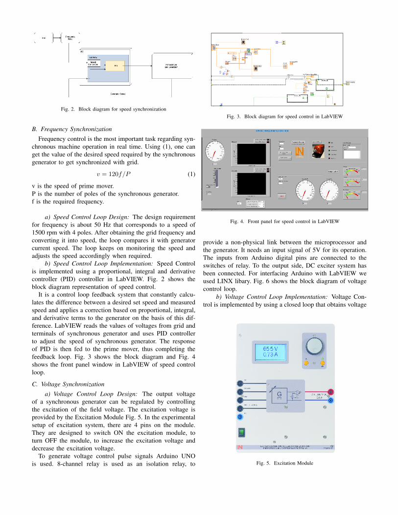
Fig. 2. Block diagram for speed synchronization
B. Frequency Synchronization
Frequency control is the most important task regarding syn-chronous machine operation in real time. Using (1), one canget the value of the desired speed required by the synchronousgenerator to get synchronized with grid.
v = 120f/P (1)
v is the speed of prime mover.P is the number of poles of the synchronous generator.f is the required frequency.
a) Speed Control Loop Design: The design requirementfor frequency is about 50 Hz that corresponds to a speed of1500 rpm with 4 poles. After obtaining the grid frequency andconverting it into speed, the loop compares it with generatorcurrent speed. The loop keeps on monitoring the speed andadjusts the speed accordingly when required.
b) Speed Control Loop Implementation: Speed Controlis implemented using a proportional, integral and derivativecontroller (PID) controller in LabVIEW. Fig. 2 shows theblock diagram representation of speed control.
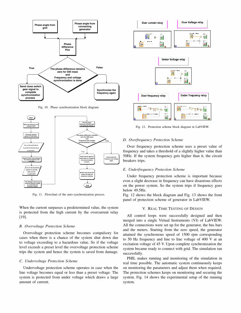
It is a control loop feedback system that constantly calcu-lates the difference between a desired set speed and measuredspeed and applies a correction based on proportional, integral,and derivative terms to the generator on the basis of this dif-ference. LabVIEW reads the values of voltages from grid andterminals of synchronous generator and uses PID controllerto adjust the speed of synchronous generator. The responseof PID is then fed to the prime mover, thus completing thefeedback loop. Fig. 3 shows the block diagram and Fig. 4shows the front panel window in LabVIEW of speed controlloop.
C. Voltage Synchronization
a) Voltage Control Loop Design: The output voltageof a synchronous generator can be regulated by controllingthe excitation of the field voltage. The excitation voltage isprovided by the Excitation Module Fig. 5. In the experimentalsetup of excitation system, there are 4 pins on the module.They are designed to switch ON the excitation module, toturn OFF the module, to increase the excitation voltage anddecrease the excitation voltage.
To generate voltage control pulse signals Arduino UNOis used. 8-channel relay is used as an isolation relay, to
Fig. 3. Block diagram for speed control in LabVIEW
Fig. 4. Front panel for speed control in LabVIEW
provide a non-physical link between the microprocessor andthe generator. It needs an input signal of 5V for its operation.The inputs from Arduino digital pins are connected to theswitches of relay. To the output side, DC exciter system hasbeen connected. For interfacing Arduino with LabVIEW weused LINX libary. Fig. 6 shows the block diagram of voltagecontrol loop.
b) Voltage Control Loop Implementation: Voltage Con-trol is implemented by using a closed loop that obtains voltage
Fig. 5. Excitation Module
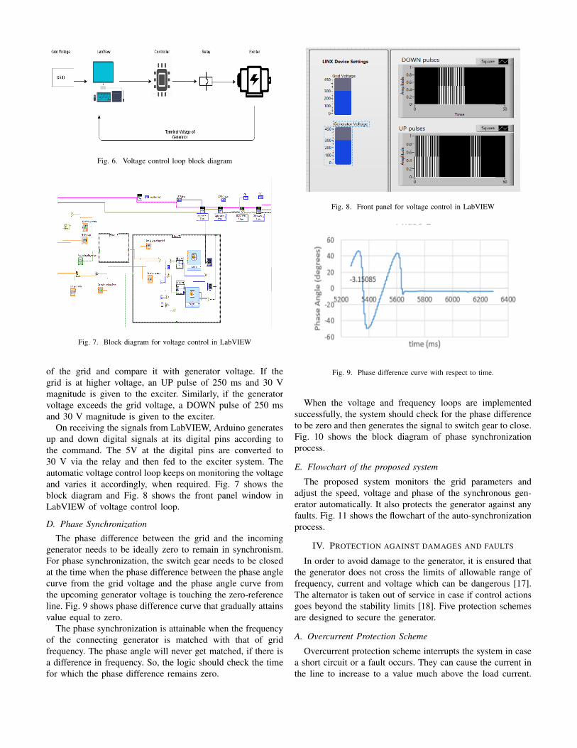
Fig. 6. Voltage control loop block diagram
Fig. 7. Block diagram for voltage control in LabVIEW
of the grid and compare it with generator voltage. If thegrid is at higher voltage, an UP pulse of 250 ms and 30 Vmagnitude is given to the exciter. Similarly, if the generatorvoltage exceeds the grid voltage, a DOWN pulse of 250 msand 30 V magnitude is given to the exciter.
On receiving the signals from LabVIEW, Arduino generatesup and down digital signals at its digital pins according tothe command. The 5V at the digital pins are converted to30 V via the relay and then fed to the exciter system. Theautomatic voltage control loop keeps on monitoring the voltageand varies it accordingly, when required. Fig. 7 shows theblock diagram and Fig. 8 shows the front panel window inLabVIEW of voltage control loop.
D. Phase Synchronization
The phase difference between the grid and the incominggenerator needs to be ideally zero to remain in synchronism.For phase synchronization, the switch gear needs to be closedat the time when the phase difference between the phase anglecurve from the grid voltage and the phase angle curve fromthe upcoming generator voltage is touching the zero-referenceline. Fig. 9 shows phase difference curve that gradually attainsvalue equal to zero.
The phase synchronization is attainable when the frequencyof the connecting generator is matched with that of gridfrequency. The phase angle will never get matched, if there isa difference in frequency. So, the logic should check the timefor which the phase difference remains zero.
Fig. 8. Front panel for voltage control in LabVIEW
Fig. 9. Phase difference curve with respect to time.
When the voltage and frequency loops are implementedsuccessfully, the system should check for the phase differenceto be zero and then generates the signal to switch gear to close.Fig. 10 shows the block diagram of phase synchronizationprocess.
E. Flowchart of the proposed system
The proposed system monitors the grid parameters andadjust the speed, voltage and phase of the synchronous gen-erator automatically. It also protects the generator against anyfaults. Fig. 11 shows the flowchart of the auto-synchronizationprocess.
IV. PROTECTION AGAINST DAMAGES AND FAULTS
In order to avoid damage to the generator, it is ensured thatthe generator does not cross the limits of allowable range offrequency, current and voltage which can be dangerous [17].The alternator is taken out of service in case if control actionsgoes beyond the stability limits [18]. Five protection schemesare designed to secure the generator.
A. Overcurrent Protection Scheme
Overcurrent protection scheme interrupts the system in casea short circuit or a fault occurs. They can cause the current inthe line to increase to a value much above the load current.
Phase angle fromgrid
Phase angle fromconnectinggenerator
Phasedifference
Plot
Synchronize thefrequency again
Send close switchgear signal to
completesynchronization
process
The phase difference remains zero for 500 msec
andFrequency and voltage
synchronization is done
True False
Fig. 10. Phase synchronization block diagram.
TurnontheprimeMover
toprovidemechnicalpower
togenerator.
Meter the frequency andvoltage of grid
Start
Calculate requiredspeed of Prime Mover
Speed Control loop achievesthe required speed by PID
controller
TurnontheExcitation
systemtoprovide
fieldcurrent
togenerator
End
Plot the phasedifference between gridand generator phases
Synchronize thefrequency and voltage
again
Thephasedifferenceremainszerofor500msec
andFrequencyandvoltagesynchronizationisdone
True
False
Send closure signal toswitch gear to complete
the synchronizationprocess
Monitor and secure thesystem through theprotection schemes
The Voltage Control loopachieves desired voltage
by controlling theexcitation system
Fig. 11. Flowchart of the auto-synchronization process.
When the current surpasses a predetermined value, the systemis protected from the high current by the overcurrent relay[19].
B. Overvoltage Protection Scheme
Overvoltage protection scheme becomes compulsory forcases when there is a chance of the system shut down dueto voltage exceeding to a hazardous value. So if the voltagelevel exceeds a preset level the overvoltage protection schemetrips the system and hence the system is saved from damage.
C. Undervoltage Protection Scheme
Undervoltage protection scheme operates in case when theline voltage becomes equal or less than a preset voltage. Thesystem is protected from under voltage which draws a largeamount of current.
Fig. 12. Protection scheme block diagram in LabVIEW.
D. Overfrequency Protection Scheme
Over frequency protection scheme uses a preset value offrequency and takes a threshold of a slightly higher value than50Hz. If the system frequency gets higher than it, the circuitbreakers trips.
E. Underfrequency Protection Scheme
Under frequency protection scheme is important becauseeven a slight decrease in frequency can have disastrous effectson the power system. So the system trips if frequency goesbelow 49.5Hz.Fig. 12 shows the block diagram and Fig. 13 shows the frontpanel of protection scheme of generator in LabVIEW.
V. REAL TIME TESTING OF DESIGN
All control loops were successfully designed and thenmerged into a single Virtual Instruments (VI) of LabVIEW.All the connections were set up for the generator, the bus barsand the meters. Starting from the zero speed, the generatorattained the synchronous speed of 1500 rpm correspondingto 50 Hz frequency and line to line voltage of 400 V at anexcitation voltage of 45 V. Upon complete synchronization thesystem became ready to connect with grid. The simulation ransuccessfully.
PHIL makes running and monitoring of the simulation inreal time possible. The automatic system continuously keepson monitoring the parameters and adjust them when required.The protection schemes keeps on monitoring and securing thesystem. Fig. 14 shows the experimental setup of the runningsystem.
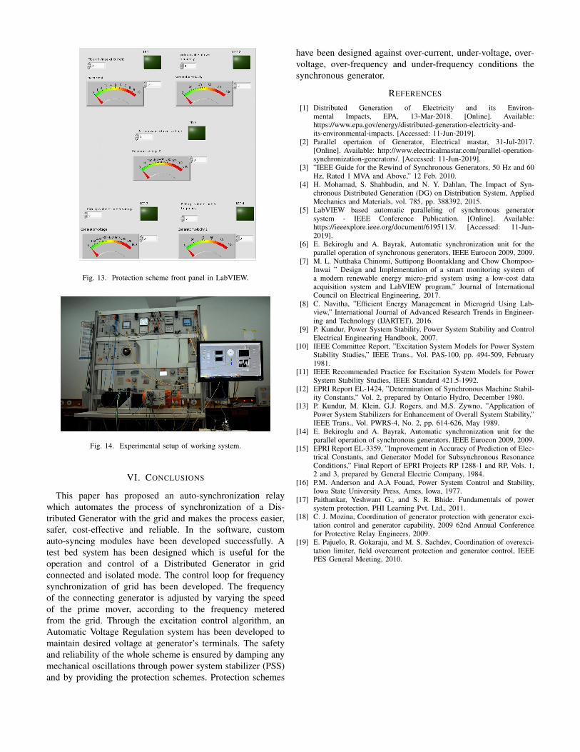
Fig. 13. Protection scheme front panel in LabVIEW.
Fig. 14. Experimental setup of working system.
VI. CONCLUSIONS
This paper has proposed an auto-synchronization relaywhich automates the process of synchronization of a Dis-tributed Generator with the grid and makes the process easier,safer, cost-effective and reliable. In the software, customauto-syncing modules have been developed successfully. Atest bed system has been designed which is useful for theoperation and control of a Distributed Generator in gridconnected and isolated mode. The control loop for frequencysynchronization of grid has been developed. The frequencyof the connecting generator is adjusted by varying the speedof the prime mover, according to the frequency meteredfrom the grid. Through the excitation control algorithm, anAutomatic Voltage Regulation system has been developed tomaintain desired voltage at generator’s terminals. The safetyand reliability of the whole scheme is ensured by damping anymechanical oscillations through power system stabilizer (PSS)and by providing the protection schemes. Protection schemes
have been designed against over-current, under-voltage, over-voltage, over-frequency and under-frequency conditions thesynchronous generator.
REFERENCES
[1] Distributed Generation of Electricity and its Environ-mental Impacts, EPA, 13-Mar-2018. [Online]. Available:https://www.epa.gov/energy/distributed-generation-electricity-and-its-environmental-impacts. [Accessed: 11-Jun-2019].
[2] Parallel opertaion of Generator, Electrical mastar, 31-Jul-2017.[Online]. Available: http://www.electricalmastar.com/parallel-operation-synchronization-generators/. [Accessed: 11-Jun-2019].
[3] ”IEEE Guide for the Rewind of Synchronous Generators, 50 Hz and 60Hz, Rated 1 MVA and Above,” 12 Feb. 2010.
[4] H. Mohamad, S. Shahbudin, and N. Y. Dahlan, The Impact of Syn-chronous Distributed Generation (DG) on Distribution System, AppliedMechanics and Materials, vol. 785, pp. 388392, 2015.
[5] LabVIEW based automatic paralleling of synchronous generatorsystem - IEEE Conference Publication. [Online]. Available:https://ieeexplore.ieee.org/document/6195113/. [Accessed: 11-Jun-2019].
[6] E. Bekiroglu and A. Bayrak, Automatic synchronization unit for theparallel operation of synchronous generators, IEEE Eurocon 2009, 2009.
[7] M. L. Nutthaka Chinomi, Suttipong Boontaklang and Chow Chompoo-Inwai ” Design and Implementation of a smart monitoring system ofa modern renewable energy micro-grid system using a low-cost dataacquisition system and LabVIEW program,” Journal of InternationalCouncil on Electrical Engineering, 2017.
[8] C. Navitha, ”Efficient Energy Management in Microgrid Using Lab-view,” International Journal of Advanced Research Trends in Engineer-ing and Technology (IJARTET), 2016.
[9] P. Kundur, Power System Stability, Power System Stability and ControlElectrical Engineering Handbook, 2007.
[10] IEEE Committee Report, ”Excitation System Models for Power SystemStability Studies,” IEEE Trans., Vol. PAS-100, pp. 494-509, February1981.
[11] IEEE Recommended Practice for Excitation System Models for PowerSystem Stability Studies, IEEE Standard 421.5-1992.
[12] EPRI Report EL-1424, ”Determination of Synchronous Machine Stabil-ity Constants,” Vol. 2, prepared by Ontario Hydro, December 1980.
[13] P. Kundur, M. Klein, G.J. Rogers, and M.S. Zywno, ”Application ofPower System Stabilizers for Enhancement of Overall System Stability,”IEEE Trans., Vol. PWRS-4, No. 2, pp. 614-626, May 1989.
[14] E. Bekiroglu and A. Bayrak, Automatic synchronization unit for theparallel operation of synchronous generators, IEEE Eurocon 2009, 2009.
[15] EPRI Report EL-3359, ”Improvement in Accuracy of Prediction of Elec-trical Constants, and Generator Model for Subsynchronous ResonanceConditions,” Final Report of EPRI Projects RP 1288-1 and RP, Vols. 1,2 and 3, prepared by General Electric Company, 1984.
[16] P.M. Anderson and A.A Fouad, Power System Control and Stability,Iowa State University Press, Ames, Iowa, 1977.
[17] Paithankar, Yeshwant G., and S. R. Bhide. Fundamentals of powersystem protection. PHI Learning Pvt. Ltd., 2011.
[18] C. J. Mozina, Coordination of generator protection with generator exci-tation control and generator capability, 2009 62nd Annual Conferencefor Protective Relay Engineers, 2009.
[19] E. Pajuelo, R. Gokaraju, and M. S. Sachdev, Coordination of overexci-tation limiter, field overcurrent protection and generator control, IEEEPES General Meeting, 2010.