Embed Size (px)
Citation preview

American Journal of Engineering Research (AJER) 2018
American Journal of Engineering Research (AJER)
e-ISSN: 2320-0847 p-ISSN : 2320-0936
Volume-7, Issue-1, pp-53-64
www.ajer.org Research Paper Open Access
w w w . a j e r . o r g
Page 53
Design and Implementation of a Vehicle Fault Detection System
(FDS) with online and SMS fault reporting: Case Study of Ford
Motors
*Fidelis C. Obodoeze1, Dr. Francis A. Okoye
2 , Ifeyinwa Nkemdilim Obiokafor
3
1(Department of Computer Engineering Technology, Akanu Ibiam Federal Polytechnic, Unwana, Nigeria)
2(Department of Computer Science, Enugu State University of Science and Technology (ESUT), Enugu, Nigeria)
3(Department of Computer Science Technology, Anambra State Polytechnic, Mgbakwu, Nigeria)
Corresponding Author: Fidelis C. Obodoeze
ABSTRACT : Vehicle fault detection has always been done by manual method. This process simply involves
trial and error processes where a mechanical engineer or auto technician is called in to diagnose automotive
device (vehicle) to detect the fault(s). Though there have being recent developments in the fault detection system
(FDS) which involves the use of an application displayed in a digital device to detect faults but this cannot send
report online to mechanics or auto technicians. The manual method involves trial and error processes with
involves series of rigorous processes before troubleshooting is completed. This method is inefficient, stressful,
time consuming, and wearing and tearing of some mechanical parts. These leads to high cost of maintenance.
The paper proposed a vehicle fault detection system that is a computer- based application with an advanced
feature of online fault reporting. This system works with the assistance of computer software which captures
and display faults for the user and also the user can send the report to the mechanics via email and SMS for
immediate response. The proposed system helps to reduce human labor and rigorous activity of trying to detect
fault. It also helps to reduce cost of troubleshooting and vehicle maintenance by cutting down on time wasted on
trial and error troubleshooting. This system was designed using the Microsoft Visual Studio.net as the frontend
and the Structured Query Language (SQL) of Microsoft-Access database as the backend to store information of
the series of faults which may have originated from the system. The system was tested and worked successfully
according to the design specification and model.
Keyword : FDI, ADC, FDS, IDE, fault, troubleshooting, scan, detect, email, sms, detection, automobile, SQL,
vehicle, RAD, display, mechanic
----------------------------------------------------------------------------------------------------------------------------- ----------
Date of Submission: 23-12-2017 Date of acceptance: 12-01-2018
----------------------------------------------------------------------------------------------------------------------------- ----------
I. INTRODUCTION Faults occur in vehicles or automobiles very often than not. This can be due to several reasons. Faults
can range from simple to complex problems such as radiator leakage or overheating, tyre pressure problems etc.
to gearbox problem, electrical, clutch, turbo, brakes, alternator, cylinder head gasket, air-conditioner condenser
problems, etc. The ability to detect and isolate these faults in complex technical systems such automobile is
important in order to fulfill dependability requirements [1]. Fault detection and isolation in automobiles is very
important because it helps to maintain high vehicle operational efficiency, low exhaust emissions, high vehicle
uptime, fuel consumption reduction or fuel economy, high vehicle safety and it guarantees efficient repair.
These factors are very important because they help to reduce overall life-cycle cost of a vehicle. Computer
system can interface with other hardware devices such as Analog-to-digital Converter (ADC), sensors, etc, to
detect and isolate faults but the software is very important so that the detected faults can be converted from
analog to digital format and be displayed as information. This information can also be conveyed to the auto
mechanics digitally online as email or sms alerts via mobile phones.According to [1], complex technical systems
aimed at commercial use are often designed for low cost and high functionality, and not primarily to facilitate
FDI. In particular, this means that there are few sensors and foremost a limited amount of hardware redundancy
in the form of multiple sensors measuring the same quantity. To achieve good performance, and at the same

American Journal of Engineering Research (AJER) 2018
w w w . a j e r . o r g
Page 54
time minimize the need for expensive redundant hardware, model-based FDI is often adopted. A model-based
FDI-system typically comprises fault detection by means of the two essential steps; residual generation and
residual evaluation. In the first step, a model of the system is used together with measurements to generate
residuals, i.e. signals that indicate whether there is a fault in the system or not. In the second step, the residuals
are evaluated with the aim to reliably detect changes in the residual behavior and make a decision whether the
change is caused by faults in the system and immediately send the analog signal to the Analog Digital Converter
who further converts it to digital signal and send it to the computer system which display the various fault
detected in the automotive device. The inherent properties of complex real-world systems in general and
automotive systems in particular, pose several difficulties and challenges when it comes to design of model-
based FDI-system.
II. RELATED WORKS Carl Svärd in [1] developed generic methods for the design of model-based Fault Detection and
Isolation (FDI) systems. The developed methods are aimed at supporting an automated design methodology so
that there is a minimum human interaction. By means of an automated design methodology the overall design
process was meant to be more efficient and systematic, which also contributes to higher quality. These aspects
are of particular importance in an industrial context. Wei Huang and Xiaoxin Su in [2] designed a fault detection
and isolation (FDI) system for an intelligent vehicle; a vehicle equipped with advanced driver assistance system
(ADAS). The ADASs are outfitted with sensors for acquiring various information about the vehicle and its
surroundings. The sensors are sensitive to faults. The FDI system is comprised of three parts: a detection part, a
decision part, and a fault management part. The detection part applies a generalized observer scheme (GOS). In
the GOS, there is bank of extended Kalman filters (EKFs), each excited by all except one sensor measurement.
The residual generated from the measurement update of each EKF is therefore sensitive to all sensor faults but
one. This way, the fault sensitivity pattern of the residual makes it possible to detect a fault and locate the faulty
sensor.
Börner, M., Isermann, R., and Schmitt, M. in [3] developed a sensor and process fault detection system
to detect wrong suspension for vehicle tyre pressures using Hitachi SH7055 microcontroller. The design
included fault detection algorithms which are proven using real measurements of tyre pressures.
M. Shahab and M. Moavenian in [4] proposed and designed a mechanism for investigating, identifying
and determining the position and size of defects in the vehicle power transmission system. This system is based
on the patterns of the residual signal, obtained from a simulated model of the system using Neuro-fuzzy
networks.
2. 1System Overview This section covers the system design which includes flowchart design, forms design and database
design.
III. SYSTEM DESIGN The system design stage involves the series of object modification and manipulations until the desired
results of the small prototype are evolved. It is this manipulation that gives rise to the newly evolved vehicle
fault detection system. The main feature guides the simulation of this application and such features include:-
1. Instant reporting fault to selected mechanic for appropriation. This feature allows vehicle
owners to report complex faults to mechanic via text messages or E-mails.
2. Continuous scanning of faulty part as vehicle are in motion and classification of faults base
vehicle parts affected.
The three design techniques are as follow:
1. Flowchart design
2. Form design
3. Database design is section covers the system design which includes flowchart design, forms
design and database design.
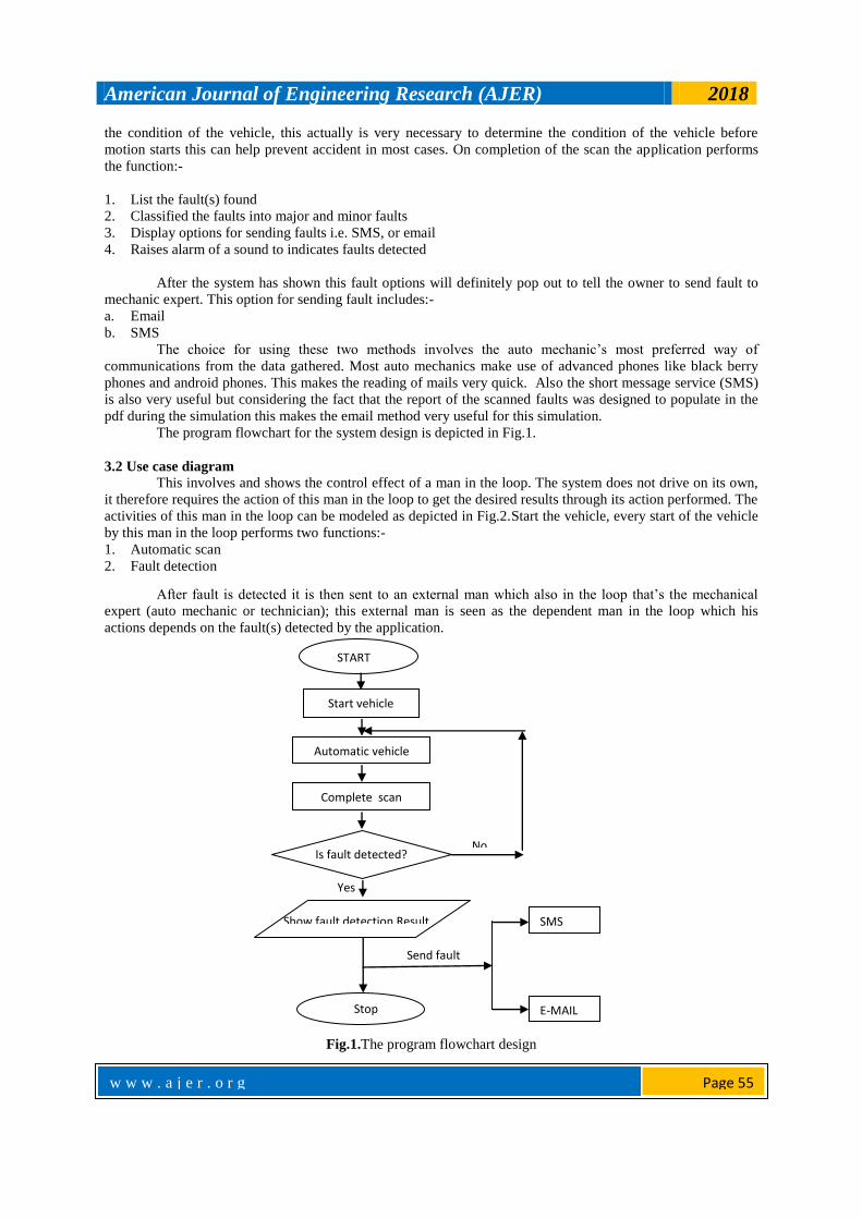
3.1 Flowchart design
The flow chart reers to the pictorial representation of the step wise process needed to be followed to
solve the problem fault detection. The first process in the flow chart involves the start process this initiate every
mechanical component
When the start process begins, the vehicle fault application is launched automatically to run a scan for
American Journal of Engineering Research (AJER) 2018
w w w . a j e r . o r g
Page 55
the condition of the vehicle, this actually is very necessary to determine the condition of the vehicle before
motion starts this can help prevent accident in most cases. On completion of the scan the application performs
the function:-
1. List the fault(s) found
2. Classified the faults into major and minor faults
3. Display options for sending faults i.e. SMS, or email
4. Raises alarm of a sound to indicates faults detected
After the system has shown this fault options will definitely pop out to tell the owner to send fault to
mechanic expert. This option for sending fault includes:-
a. Email
b. SMS
The choice for using these two methods involves the auto mechanic’s most preferred way of
communications from the data gathered. Most auto mechanics make use of advanced phones like black berry
phones and android phones. This makes the reading of mails very quick. Also the short message service (SMS)
is also very useful but considering the fact that the report of the scanned faults was designed to populate in the
pdf during the simulation this makes the email method very useful for this simulation.
The program flowchart for the system design is depicted in Fig.1.
3.2 Use case diagram This involves and shows the control effect of a man in the loop. The system does not drive on its own,
it therefore requires the action of this man in the loop to get the desired results through its action performed. The
activities of this man in the loop can be modeled as depicted in Fig.2.Start the vehicle, every start of the vehicle
by this man in the loop performs two functions:-
1. Automatic scan
2. Fault detection
After fault is detected it is then sent to an external man which also in the loop that’s the mechanical
expert (auto mechanic or technician); this external man is seen as the dependent man in the loop which his
actions depends on the fault(s) detected by the application.
Fig.1.The program flowchart design
Start vehicle
Automatic vehicle
scan
Is fault detected?
Show fault detection Result
Yes
Stop
No
START
Send fault
SMS
Complete scan

American Journal of Engineering Research (AJER) 2018
w w w . a j e r . o r g
Page 56
Fig. 2. User Case diagram design
3.3 Form design
This system makes use of a simulation prototype to demonstrate the various actions to be performed by
this man in the loop at every process of vehicle fault detecting.The system design is the most important circle in
software development with regards to model used. Rapid Application Development (RAD) was used to design
the system. It is done in such a way that development continues while optimization can be made and changes are
effected to meet up with the users requirement. During system design, the flowchart and use case diagram were
considered to be very important. For this simulation the form design was considered in three levels as follow.
3.4 Interactive level
This level involves the entire interactive component that ensures that the software reach the
requirement for deployment in this level we would talk about the application forms used for the software and the
numbers of forms used are four and they include :-
3.5 Startup form
The startup application form is the first form every user sees immediately (as shown in Fig.3), for this
simulation the start up form will be loaded automatically and progress bar that was used to indicate the level of
the scan performed after initialization, the most important feature of this is progress bar which shows level of
scan completed.
Fig.3.The startup form
American Journal of Engineering Research (AJER) 2018
w w w . a j e r . o r g
Page 57
3.6 How this form was designed:
1. Open visual studio design IDE
2. Create a project and name it vehicle fault detection system
3. Click on save
4. Go to the project menu click on add splash screen
5. Go to the tools menu drag and drop image
6. Go to the properties of the image select background image from import local.
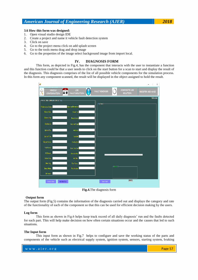
IV. DIAGNOSIS FORM This form, as depicted in Fig.4, has the component that interacts with the user to instantiate a function
and this function could be that a user needs to click on the start button for a scan to start and display the result of
the diagnosis. This diagnosis comprises of the list of all possible vehicle components for the simulation process.
In this form any component scanned, the result will be displayed in the object assigned to hold the result.
Fig.4.The diagnosis form
Output form
The output form (Fig.5) contains the information of the diagnosis carried out and displays the category and rate
of the functionality of each of the component so that this can be used for efficient decision making by the users.
Log form
This form as shown in Fig.6 helps keep track record of all daily diagnosis’ run and the faults detected
for each part. This will help make decision on how often certain situations occur and the causes that led to such
situations.
The Input form
This input form as shown in Fig.7 helps to configure and save the working status of the parts and
components of the vehicle such as electrical supply system, ignition system, sensors, starting system, braking

American Journal of Engineering Research (AJER) 2018
w w w . a j e r . o r g
Page 58
system, engine components, engine cooling system and fuel supply system.
Fig.5.The output form
Fig.6.The Log form

American Journal of Engineering Research (AJER) 2018
w w w . a j e r . o r g
Page 59
Fig.7.The Input form
Manipulating model:
This model is concerned with the special code that is used to interact with this hardware device to
perform the required function specified in the design of the system.
Storage level
This level is concerned with the kind of database used to store the information and the security measure
applied to the database to help retain data integrity throughout the system usage.
Control principles:
1. The principles are divided into four sections:
2. Control elements
3. Operational elements
4. Display elements and
5. Supplementary elements.
We established a total of twelve principles. Each principle defines the minimum (provisions/
recommendations) to be fulfilled for the VFD to allow the driver to easily and accurately understand and judge
driving situations and effectively use the control system according to their intentions. The section on control
elements and operational elements is divided into those for normal situations and those for critical situations,
and an explanation is given on how the control system should be operated. In the section on display elements,
the discussion covers the notification of normal functionality, failure, reduction in the scope of functionality,
and the transfer of control. The section on supplementary elements includes a warning against over-reliance on
sensors and systems, which is potentially dangerous, and discusses the use of standard symbols and information
for road users. In this document, normal driving refers to situations that do not require immediate responses
from the driver and/or vehicle to avoid a collision. Critical driving refers to situations that do require immediate
responses from the driver and/or vehicle to avoid or mitigate a collision.

American Journal of Engineering Research (AJER) 2018
w w w . a j e r . o r g
Page 60
1. Control elementsSystem actions should be easy to override at any time under normal driving situations and
when collisions are avoidable.
2. Explanation: One of the main objectives of ADAS such as ACC, etc., used in normal driving situations, is
to reduce the driving workload. During normal driving, the system should be capable of being overridden
by the driver using simple, deliberate action(s) at any point in time.When a collision is determined to be
imminent, the system can take actions intended to avoid and/or mitigate the crash severity.
3. Explanation: In critical driving situations where the driver has not taken proper avoidance actions because
of impairment, distraction, inattention, or other unforeseen incidents, it should be possible to apply system
intervention to try to avoid the collision or mitigate the crash severity.
4. Operational elements:For systems that control the vehicle under normal driving situations, the driver
should have a means to transition from ON to OFF manually and to keep the system in the OFF
state.
5. Explanation: For ease of use and/or convenience in driving, the driver’s intentions should be ensured as a
priority, so that the driver can switch the state of control from system to driver that is from ON to OFF and
the OFF state should be kept under the driver’s operation. Systems that control the vehicle under critical
driving situations, the initial set state of the system should be ON.
6. Explanation: For collision avoidance and/or mitigation, the first priority is to reduce trauma, therefore the
system status ON should be maintained during driving. However, accounting for driver preferences, the
system can be equipped with a manual OFF switch. In this case the system status should be recognizable to
the driver
7. Display elementsDrivers should be provided with clear feedback informing them when the system is
actively controlling the vehicle’s speed and/ or path.
8. Explanation: When the system is actively controlling the vehicle, the driver should be provided with clear
feedback on its activation. The driver has to be made aware of system activation so as to properly manage
driving a car with assistance systems. Drivers should be informed of the system status when system
operation is malfunctioning or when there is a failure.
9. Explanation: When the system is malfunctioning or has failed, the driver should be informed of the system
status. This is needed to avoid any misunderstanding by the driver that the system is still working. The
driver should be informed when the system detects that conditions are such that normal performance
cannot be assured.
10. Explanation: When the system is not fully functioning, for example, the sensor performance is impaired
under certain driving conditions such as rain or when road markings are not visible, the driver should be
informed of the status to allow a smooth transfer of control to the driver. Drivers should be notified of any
system-initiated transfer of control between the driver and vehicle.
11. Explanation: Transfer of control between the driver and the vehicle would be the point when automation is
realized. Any transfer of control should be transparent to the driver, but at the very least, the driver should
be notified of any transfer initiated by the system so the driver is always aware if they have control of the
vehicle.
12. Supplementary elements:In cases where systems automatically control the longitudinal and lateral
behavior of the vehicle and the driver’s task is to monitor system operations, appropriate arrangements
should be considered to prompt the driver to maintain their attention to the vehicle, road and traffic
situation.
13. Explanation: When the driver is using highly automated systems such as ACC with LKS, which is the
automation of longitudinal and lateral control, the driving tasks are reduced and the driver simply monitors
the systems and surroundings. In these situations, it is important to ensure the driver’s attention to the
driving task is maintained. To ensure that the driver stays aware of the driving situation, appropriate
measures should be considered to keep the driver in-the-loop. Drivers should be notified of the proper use
of the system prior to general use.
14. Explanation: The manufacturer should provide information on correct system use to avoid any
misunderstanding and/or over-dependence on the system. For example, it is required that the driver
understand what assistance systems are installed in the vehicle, and that instructions be provided on the
physical limitations of the system functions prior to its use.If symbols are used to notify the driver, a
standard symbol should be used if available.
15. Explanation: Taking into account the use of different and/or unfamiliar vehicles, commonality of
American Journal of Engineering Research (AJER) 2018
w w w . a j e r . o r g
Page 61
information should be secured, therefore standard symbols should be used, if available. Regulation No.121
could be the one that might be referred System actions requiring the attention of other road users should be
signaled to other road users.
16. Explanation: To help surrounding road users, such as other drivers, pedestrians, and cyclists, be aware of
vehicle actions, the system’s actions should be signaled when braking, changing lanes or for hazards. In
consideration of the system functions and driving situation, the need for display might be determined on a
case-by-case basis.
V. INPUT ANALYSIS All input from the system comes from the ADC device after conversion of the digital signal has being
made and its sent to the computer system for interpretation from 0s and 1s to the high level form which is
understood by the human to take decision.
5. 1 Database Design
The input table database design is depicted in Table 1.
Table 1. Input table database
Field Name Data Type Length
Mechanical Part Binary 0>
Fault Analysis Binary 0>
Description Binary 0>
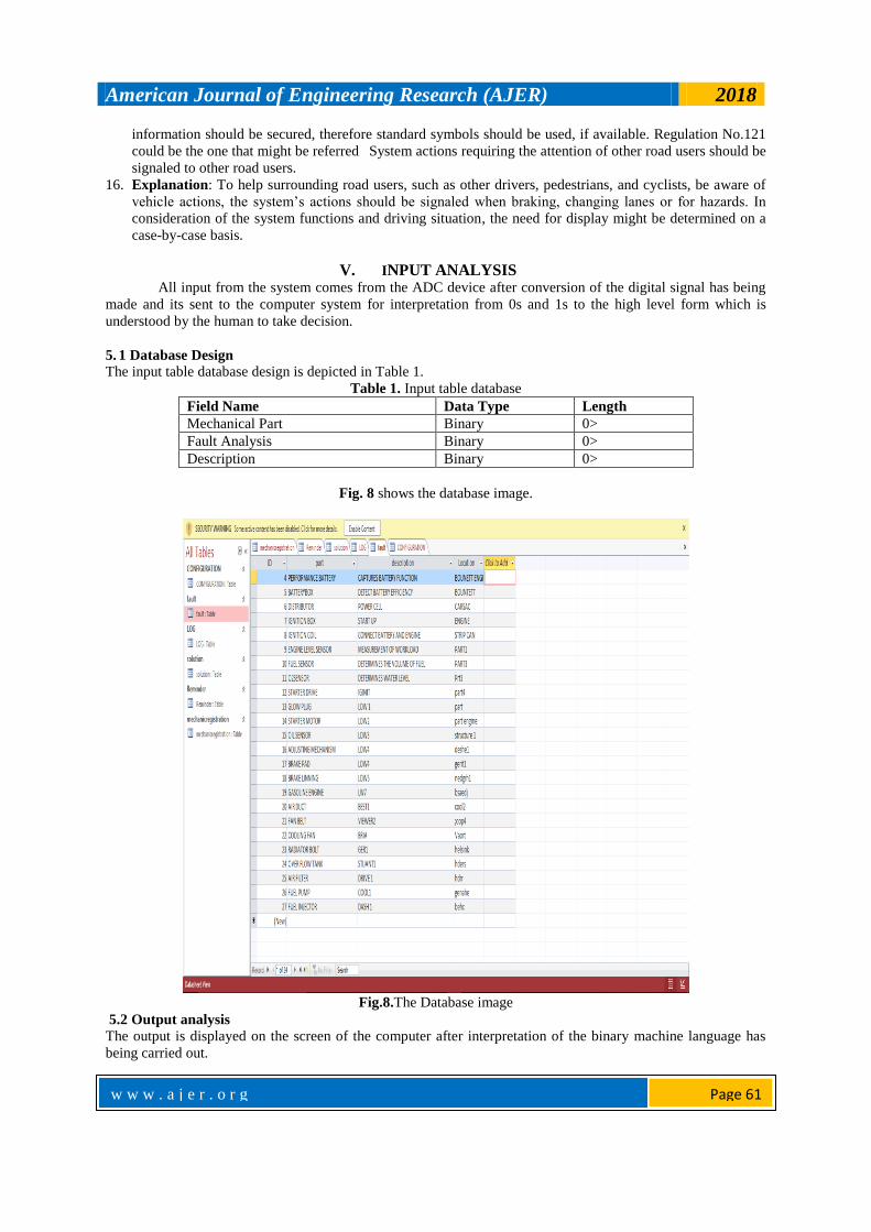
Fig. 8 shows the database image.
Fig.8.The Database image
5.2 Output analysis
The output is displayed on the screen of the computer after interpretation of the binary machine language has
being carried out.

American Journal of Engineering Research (AJER) 2018
w w w . a j e r . o r g
Page 62
Table 2. Output Analysis Field Name Datatype Length Oop Object
Mechanical Part Text 0> Label
Diagonisis Status Text 0> Label
Date Text 0> Label
Part State Text 0> Label
5.3 System implementation After successful methodology and analysis of the system, the system was implemented on a software
IDE platform. This platform makes use of the drag and drop method i.e. if the system requires the placement of
a textbox or label object to display information the tools of the IDE were utilized to place the objects and then
dragged and placed on the form.
Connecting to the connection string requires Dim cn As New OleDb.OleDbConnection
cn.ConnectionString = "Provider=Microsof.accdb;Persist Security Info=False;"
cn.Open()
The system was implemented using the Microsoft Visual Studio 2010 as the frontend for designing of
interface and manipulating level code and SQL statements using MS Access was used as the backend. During
the implementation of the system certain factors were considered and they include:-
1. Independent platform The system was implemented in such a way that it can run independently of any platform which is a vital
improvement in the use of this language so that it can be deployed to any vehicle and would still perform its
function.
2. Up time constraint The system is going to be in uptime state once the car is on, because it is meant to detect the situation of the
vehicle even at run-time of the vehicle.
3. Interactive constraint The system was implemented with forms on the IDE which interact with users during the uptime in a unique
way.
4. Hardware requirement
There are specific requirements which the system must meet for it to function effectively. These requirements
can be specified into hardware requirement and software requirements.
The hardware requirements refer to the physical components of the system that interact with human using the
software. These include:-
1 Computer system
2 Hard disk capacity of 250 GB
3 FDI (Fault Detection and Isolation)
4 RAM capacity of 1GB
5 ADC (Analog Digital Converter)
5. Software requirements
These refer to the software application itself which the users interact with to get the necessary
information sent by the ADC. These software can be of two categories- application software and system
software. The specific software requirements for this design include Windows Operating System (OS), Visual
Studio IDE, MS Access and Microsoft .Net framework.
6. Application software:
This is software which is concerned with set of instructions written to interact with a confined
hardware material and fault detection and isolation falls under application software because it is confined to a
vehicle’s devices. This application software can be built and compiled in several compatible devices. The
application software is always written for specific purpose like this case the software was designed to detect

American Journal of Engineering Research (AJER) 2018
w w w . a j e r . o r g
Page 63
fault in vehicles.
7. System software
The system software is important software that manages user application and other programs which
runs in the system and tend to control the activities of the system files and applications so they are very
important in every computer system.
8. System mode of operation:
Due to its activity of constantly detecting faults during up time of the vehicle its mode of operation
would always be Debug mode this mode is the state of activeness of the system and always ready to detect and
report adequately any requirement that is not functioning properly or occurrence of abnormality.
9. Systems Testing:
After the successful implementation of the system the system was tested to know if it met the standard
requirement before deployment and any requirement that was met is simply implemented according to the
software model used. When the test was carried out overheating was not detected by the system due to the
analog digital converter device was faulty and no signal was sent so this was just detected manually and fixed by
changing the Analog digital converter. After the changing of the required component the system was functional
and produced the output result.
Table 3. Test output table Field/
Name
Fault Method Of
Diagonisis
Possible Solution Date Description
Car Engine Overheating
Vehicle Fault Detection Software
Consult The Mechanical Expert
12/062017
This Was Caused By The Constant Supply Of Heat
Without Mechanism For
Absorption Of The Heat
Maintenance technique of the software:
1 Constantly carry out a disk check using the command prompt to access the current situation of the
software.
2 Ensure that no other program is installed on device to avoid code alteration by virus
3 Constantly scan your system for malicious attack.
Deployment Technique:
The system would be deployed during construction of the vehicle so the right of deployment of this
software would be given to vehicle manufacturers in a executable file. Also the system can be installed and
uninstalled
VI. RESULTS AND DISCUSSION After testing the system was functional and produced expected results. There was overheating fault in
the vehicle and the system detected it and sent the result to a mechanical expert’s email and mobile phone as
SMS alert.
VII. CONCLUSION The vehicle fault detection software was developed, tested and implemented successfully according to
the specification of the system model. This software was designed to have five forms which interact with the
users in every possible way to display faults that has been detected by the FDI. The computer system is able to
understand digital signal coming from the ADC and manipulate the signal and translate them to high level
language. Every activity of faults concerning the vehicle can be tracked and also be generated by the log form
for observation and decision making. After development of the system, maintenance is required to be carried out
to increase and maintain the working efficiency of the software as described in the system implementation.
Every activity begins with the starting up of the vehicle because that ignites the battery and send power to the
system, so an individual just need to press the on button of the system . The design and implementation of this
automated software became necessary because the manual diagnosis method is inefficient.
VIII. RECOMMENDATIONS 1. Instruction manual has been developed on how to use the system so it is recommended that this instruction
is followed strictly.
2. The system can only detect faults but not resolve the faults so users should ensure they report any slight in

American Journal of Engineering Research (AJER) 2018
w w w . a j e r . o r g
Page 64
change of any mechanical functional part as valuable human life can be lost due to negligence.
3. The system can be upgraded in future to incorporate faults scan for other popular vehicle brands in Nigeria
such as Toyota, Honda, Mercedes and Nissan.
REFERENCES [1]. Carl Svärd, "Methods for Automated Design of Fault Detection and Isolation Systems with Automotive Applications", Final year
project thesis, Department of Electrical Engineering Linköping, Linköping University, Institute of Technology, Swdeden, 2012, pp.1.
[2]. Wei Huang and Xiaoxin Su, "Design of a Fault Detection and Isolation System for Intelligent Vehicle Navigation
System",nternational Journal of Navigation and Observation, Volume 2015 (2015). Retrieved online at https://www.hindawi.com/journals/ijno/2015/279086/.
[3]. Börner, M., Isermann, R., and Schmitt, M., "A Sensor and Process Fault Detection System for Vehicle Suspension Systems," SAE
Technical Paper 2002-01-0135, 2002, https://doi.org/10.4271/2002-01-0135. [4]. M. Shahab and M. Moavenian, "Fault Detection and Isolation of Vehicle Driveline System", International Journal of Automotive
Engineering, Vol. 2, Number 2, April 2012, pp.84-94. Accessed online at http://ijae.iust.ac.ir/article-1-117-en.pdf.
Authors Profile
Engr. Fidelis Chukwujekwu Obodoeze is a Lecturer at the Department of Computer Engineering, Akanu Ibiam
Federal Polytechnic Unwana, Nigeria. He has authored and published over thirty research papers in both local and
international journals. His research interests include Cryptography, Embedded systems, Software Engineering,
Wireless Telecommunication security, Wireless Sensor Networks, Information and Data security, Artificial
Intelligence and Industrial Automation. He had his Masters (MEng.) in Control Systems and Computer Engineering
at Nnamdi Azikiwe University Awka, Nigeria in 2010 and Bachelor of Science degree (B.Sc.) in Computer
Engineering at Obafemi Awolowo University Ile-Ife, Nigeria in 2000. He is registered member of several
professional bodies including COREN, Nigerian Society of Engineers (NSE), Nigerian Institution of Electrical and
Electronic Engineers (NIEEE), International Association of Engineers (IAENG), Institute of Research and
Development Institute (IRDI), Fellow Institute of Industrial Administrators (FIIA) of Nigeria. He is currently
rounding off his Doctoral programme at Nnamdi Azikiwe University Awka, Nigeria. All correspondence to email:
Ifeyinwa Nkemdilim Obiokafor is a Higher Instructor at the Department of Computer Science Technology
Anambra State Polytechnic Mgbakwu, Nigeria. She had her HND and Postgraduate Diploma (PGD) in both
Computer Science. She is presently rounding off her M.Sc, programme in Computer Science at Nnamdi Azikiwe
University Awka, Nigeria.
Email: [email protected]
Dr. Francis A. Okoye is a senior lecturer and Head Department of Computer Science and Engineering Enugu
State University of Science and technology (ESUT), Nigeria. He had his Ph.D in Computer Science in 2008 at
Ebonyi State University Abakaliki; MSc. and BEng. in Computer Science and Engineering at Enugu State
University of Science and Technology (ESUT), Nigeria in 2001 and 1996 respectively. His research interests are
on Data and Information security, Artificial Intelligence, ICT Automation, Software Engineering, etc. He has
authored several academic papers in both local and international journals. He had several years of teaching,
administrative and research experiences. Email: [email protected]
Fidelis C. Obodoeze."Design and Implementation of a Vehicle Fault Detection System (FDS) with
online and SMS fault reporting: Case Study of Ford Motors.” American Journal of Engineering
Research (AJER), vol. 7, no. 1, 2018, pp. 53-64.