Embed Size (px)
Citation preview
1
Design and Implementation of a TDD-Based128-Antenna Massive MIMO Prototyping System
Xi Yang, Student Member, IEEE, Wen-Jun Lu, Member, IEEE, Ning Wang, Member, IEEE, Karl Nieman,Shi Jin, Member, IEEE, Hongbo Zhu, Xiaomin Mu, Member, IEEE, Ian Wong, Yongming Huang, Member, IEEE,
and Xiaohu You, Fellow, IEEE
Abstract—Spurred by the dramatic mobile IP growth and theemerging Internet of Things (IoT) and cloud-based applications,wireless networking is witnessing a paradigm shift. By fullyexploiting the spatial degrees of freedom, the massive multiple-input-multiple-output (MIMO) technology promises significantgains in both data rates and link reliability. This paper presentsa time-division duplex (TDD)-based 128-antenna massive MIMOprototyping system designed to operate on a 20 MHz band-width. Up to twelve single-antenna users can be served by thedesigned system at the same time. System model is providedand link-level simulation corresponding to our practical TDD-based massive MIMO prototyping system is conducted to validateour design and performance of the algorithms. Based on thesystem hardware design demonstrated in this paper, both uplinkreal-time video and downlink data transmissions are realized,and the experiment results show that 268.8 Mbps rate wasachieved for eight single-antenna users using QPSK modulation.The maximum spectral efficiency of the designed system willbe 80.64 bit/s/Hz by twelve single-antenna users with 256-QAMmodulation.
Index Terms—massive MIMO, prototyping system, softwaredefined radio, TDD.
I. INTRODUCTION
OVER the next five years, the global IP traffic is goingto increase more than threefold and will have achieved
a hundredfold increase from 2005 to 2020 [1]. The increasingpopularity of smart portable devices, e.g., smartphones andtablets, and the worldwide success of the third generation(3G) and the long-term evolution (LTE) cellular standards,are making the mobiles lead the IP traffic growth. Behindthe same rapid growth in the mobile Internet traffic, we havebeen seeing a dramatic change in the growth pattern in recentyears due to the rise of the machine-to-machine (M2M) typecommunications and the prosper of the Internet of Things(IoT) market. There is a demand for a redefined cellulararchitecture to provide good native support to the numerousemerging applications and to improve quality-of-service (QoS)provisioning for a large diversity of communication scenariosin future wireless networking.
The fifth generation (5G) cellular system, which is expectedto be rolled out by 2020 according to the IMT-2020 road map,is going to be a paradigm shift of mobile networking. In orderto achieve the key performance indices (KPIs) and visionsof 5G, simple evolutions from existing wireless technologiessuch as 3GPP LTE and Wi-Fi is not sufficient. Disruptivenew technologies on both the network side and the user sidemust be introduced, among which the massive multiple-input-multiple-output (MIMO) is considered as the most significant
breakthrough in base station (BS) technologies [2]. Differentfrom the conventional multi-user MIMO (MU-MIMO), byusing a large excess of very low power BS antennas to servea relatively small number of user equipments (UEs) over thesame time-frequency resource block, massive MIMO promisessignificant gains in wireless data rates and link reliability.In the past few years, the massive MIMO technology hasbeen attracting increasing attention from both academia andindustry and become one of the most dynamic research topicsin wireless communications [3], [4].
It is shown in [5] that in a time-division duplex (TDD)massive MIMO system equipped with unlimited number of BSantennas, the MU-MIMO channel is asymptotically orthogonalwhen the channel coefficients for different antenna elementsare independent and identically distributed (i.i.d.). Therefore,by fully exploiting the spatial degrees of freedom of the large-scale antenna array, the hardware-friendly linear precodingschemes, e.g., maximal-ratio transmitting (MRT) and zero-forcing (ZF), which can be implemented with channel stateinformation (CSI) acquired from uplink pilot based channelestimation, is sufficient to achieve the optimal performanceasymptotically. In addition, the work of Ngo [6] presentsthat with perfect CSI, each single-antenna UE in a massiveMIMO system can scale down its transmit power proportionalto the number of antennas at the BS to achieve the sameuplink performance as in single-input single-output (SISO)transmissions. Similarly, in the imperfect CSI scenario, thescaling coefficient for the UE transmit power is the square rootof the number of BS antennas. This leads to higher energyefficiency and is very important to future wireless networkswhere excessive energy consumption is a growing concern.
While the massive MIMO technology has many featuresdesirable in future wireless networking, the use of large-scaleantenna array raises new issues that must be addressed inthe design of massive MIMO based wireless systems. Firstof all, it becomes increasingly difficult to obtain accurateinstantaneous CSI at transmitter (CSIT) for the downlink,especially when the system operates in frequency-division du-plex (FDD) mode. The pilot overhead in FDD-based massiveMIMO system for downlink CSIT acquisition is shown tobe proportional to the BS antenna array size [3]. Moreover,even in TDD mode, there exists hardware mismatch betweenthe BS and the UE, which impairs channel reciprocity andnecessitates calibration before downlink transmission [4], [8]–[10], [13]. Furthermore, due to the use of large excess antennaarrays at the BSs, the hardware complexity and computational
arX
iv:1
608.
0736
2v1
[cs
.IT
] 2
6 A
ug 2
016
2
complexity are significant and they increase with the sizeof the antenna arrays, which poses new challenges to thedesign and implementation of massive MIMO based systemsin: 1) flexible software defined radio (SDR) solution to receiveand send radio-frequency (RF) signals, 2) precise time andfrequency synchronization among different RF devices, 3)high throughput bus to transfer and collect massive data, and4) high processing power required by the real-time signalprocessing in the execution of physical layer (PHY) andmedia access control layer (MAC) functionalities. Despitethe aforementioned challenges, it is of great significance tobuild prototyping massive MIMO system to help verifying itspotentials and perfecting the technology before commercialdeployments. Fortunately, there are several basic prototypingworks on massive MIMO such as the Argos [15]–[17] andthe LuMaMi [14]. Several leading communication networkequipment manufacturers such as Huawei and Nokia SiemensNetworks have also involved in massive MIMO related re-search and development activities.
The Argos developed by the Rice University team in col-laboration with Alcatel-Lucent shows the feasibility of themassive MIMO concept with a 64-antenna array prototypein indoor environments. By using hierarchical and modulardesign principles, Argos achieves scalability and flexibility inits implementation. Argos V1 [17] built a 64-antenna BS andserved 15 single antenna users simultaneously through ZF andmulti-user beamforming with 0.625 MHz bandwidth in TDDmode where channel reciprocity holds. Channel measurementswere collected for both line-of-sight (LOS) and non-line-of-sight (NLOS) scenarios and the the experimental results forcell capacity were presented. Argos V2 [15], which is anupgraded version of Argos V1, extended the number of BSantennas to 96 and supported 32 simultaneous data streams.Both Argos V1 and V2 are built based on commercially avail-able hardware, e.g., Wireless Open Access Research Platform(WARP) which has an open programmable FPGA and two RFchains on board. The LuMaMi (Lund Massive MIMO) [14]is an SDR-based testbed employing a modular architectureand supports up to 100 transceiver chains at the BS over20 MHz orthogonal frequency division multiplexing (OFDM)bandwidth. Similar to the WARP, each module in the LuMaMisystem contains both RF and signal processing components.
In order to alleviate the overwhelming processing burden ofdata transmission and signal processing due to the dramaticallyincreased BS antenna array size, distributive implementationof functionalities such as MIMO detection and precoding isadopted, where the hardware system is divided into subsys-tems, i.e. smaller groups of modules, and the processing poweris evenly distributed among the subsystems. While all databytes to transmitted are generated at a central controller whichis a separate processing unit, the radio frequency band of anOFDM symbol is divided into several sub-bands such thateach sub-band is assigned to a subsystem which is responsiblefor the processing of the RF signal of the subsystem itselfand the baseband processing of the sub-band of the wholesystem. Specifically, for the uplink, each subsystem splits itsreceived RF signals into sub-band signals and distributes thesub-band signals to responsible subsystems. After collecting
the sub-band signals from all the subsystems, each subsystemconducts baseband signal processing, whose output is thenfed to central processing unit. Similarly, in the downlink eachsubsystem receives baseband signal of its responsible sub-bandfrom the central baseband processing unit and conducts MIMOprecoding. Each subsystem then distributes the responsibleprocessing output to other subsystems. After collecting thesub-band signals from all the subsystems, each subsystemconducts RF signal processing and performs data transmission.
However, existing works on prototyping massive MIMOhave limitations in terms of suitability for commercial im-plementations. Firstly, although both Argos and LuMaMi areoperated in TDD mode, there is urgently lack of a clear link-level procedure illustration for TDD data transmission corre-sponding to the practical testbeds. Secondly, only 0.625 MHzbandwidth downlink channel with 64 BS antennas and 100-antenna MIMO uplink over 20 MHz bandwidth are realizedby Argos and LuMaMi, respectively, which is insufficient forreal world massive MIMO deployments. In addition, the com-munication air interface configuration with TDD, includinginitial RF chain calibration, uplink channel estimation fromuplink pilot symbol, uplink data transmission, TDD switching,downlink precoding, downlink pilot and data transmission etc.are not available. Hence, there is a demand for continued efforton massive MIMO prototyping testbed development from bothacademia and industry.
In this paper, we try to resolve the aforementioned limita-tions of existing work and present design and implementationof a TDD-based 128-antenna massive MIMO prototypingsystem based on SDR platform. The designed system can serveup to twelve single antenna users on the same frequency-timeresource block and a resource demanding video streaming ser-vice is used to test our design. Similar to Argos and LuMaMi,because of flexibility and scalability considerations, we havedivided our 128 antenna massive MIMO prototyping systeminto subsystems with each subsystem consisting of 16 antennas(8 modules). In order to improve the computational capabilityto handle the massive baseband data (about 6.45 GB/s), fourFPGA co-processors are used in the system. Moreover, boththe hardware and the software utilized by our system are builtwith commercially available products/solutions, which makesour system stable, friendly for customization, and sufficientaccurate. The main contributions of this work are summarizedin the following:
a) A link-level communication procedure illustration andsystem simulation of our TDD-based 128-antenna mas-sive MIMO prototype design are presented. Hardwaremismatch between the BS and UEs for the uplink anddownlink channel measurements is considered in thelink-level simulation. The emulation of the real link-level processing procedure for the prototyping system istherefore of great value to evaluation of the processingalgorithms implemented, e.g., reciprocity calibration andmulti-user precoding.
b) We have designed and built a practical TDD-based128 antenna massive MIMO prototyping system, whichrealizes eight single-antenna users’ real-time over-the-air uplink and downlink data transmission based on air

3
interface synchronization through primary synchroniza-tion signal (PSS).
c) The real-time measurements of the 20 MHz bandwidthmulti-user massive MIMO channel are presented, andthe impact of the reciprocity calibration is also studied.
The rest of this paper is organized as follows. To givea clear overview of the practical massive MIMO system inprinciple, the theoretical system model is given in Section II.Section III describes the system link-level simulation in detail.The system design and experiment setup for validating ourprototype design are presented in Section IV, and Section Vpresents the corresponding experimental results. Concludingremarks are given in Section VI.
Notation: We use uppercase and lowercase boldface lettersto denote matrices and vectors, respectively. The N × Nidentity matrix is denoted by IN , the all-zero matrix is denotedby 0, the all-one matrix is denoted by 1. ek ∈ RK×1
represents the kth unit vector, i.e., the vector which is zeroin all entries except the kth entry which it is set to 1. Thesuperscripts (·)H , (·)T , and (·)∗ stand for the conjugate-transpose, transpose, and conjugate operations, respectively.
II. SYSTEM MODEL
In this section, the analytical model for TDD-based mas-sive MIMO system is presented. This offers an overview ofthe fundamentals and basis behind the proposed prototypingsystem design, which helps the readers to better understandour design principles and the subsequent results.
A. Communication Scenario
Consider a single-cell multi-user (MU) massive MIMOsystem adopting N -subcarrier OFDM. The base station isequipped with M antennas and simultaneously serves K(K � M ) randomly distributed single-antenna users in thesame time-frequency resource block, as shown in Fig. 1.The system operates in TDD mode, and Fig. 2 is the framestructure adopted. Specifically, a 10 ms radio frame is dividedinto 10 subframes. Except for Subframe 0, which is used forsynchronization between the BS and UEs through PSS, allthe other subframes, i.e. Subframe 1 through Subframe 9,are used for data transmission and have the same structureof two 0.5 ms time slots. Each time slot consists of sevenOFDM symbols as shown in Fig. 2 and the configuration canbe adjusted flexibly to meet the data transmission demand indifferent scenarios. Note that the Guard symbol is reservedfor TDD switch. In this example, we allocate two OFDMdata symbols for the uplink because of the real-time videostreaming application to be used to test the prototyping system.
B. Uplink Data Transmission
Before the uplink data transmission, uplink pilot symbolis firstly transmitted by the K single-antenna users (labeledas UE0, . . . ,UEK−1) for channel measurements at the BS.We adopt frequency orthogonal pilots for different users andzero-hold method is utilized in the least square (LS) channelestimation. The K neighbouring subcarriers are successively
M antennas
User 1
User 2
User 3
User K …
U
KhD
Kh
Fig. 1. A single-cell multi-user (MU) massive MIMO system. BS isequipped with M antennas and simultaneously serves K (K � M ) randomlydistributed single-antenna users in the same time-frequecny resource.
Subframe 0 Subframe 1 Subframe 2 Subframe 3 …… Subframe 9
a 10ms Radio Frame
subframe
UL P
ilot
PSS
Gu
ard
… …
Gu
ard
14 OFDM Symbol
UL D
ata
UL D
ata
Gu
ard
DL P
ilot
DL D
ata
slot
Gu
ard
7 OFDM Symbol
Sync Subframe
Data Subframe
Fig. 2. Frame structure. A 10 ms radio frame has been divided into 10subframes. Subframe 0 is used for synchronization between the BS andUEs, Subframe 1 to Subframe 9 are used for data transmission, where eachsubframe is composed of two 0.5 ms slots and each slot consists of sevenOFDM symbols: Uplink (UL) Pilot, UL Data, UL Data, Guard, Downlink(DL) Pilot, DL Data, and Guard.
allocated to K users, e.g., Subcarrier 0 for UE0, Subcarrier 1for UE1, . . . , Subcarrier K−1 for UEK−1, Subcarrier K againfor UE0 and so forth. Details about the resource allocationscheme is illustrated in Section III. Furthermore, we groupevery K consecutive subcarriers into a sub-band which givesN/K sub-bands marked as Sub0, Sub1, . . . and SubN/K− 1.Each user only transmits pilot on its pilot subcarrier and theother K − 1 subcarriers on the sub-band are preserved. Oncethe channel is estimated for UEk, k = 0 . . .K − 1 by thepilot on Subcarrier n in Subi, i.e. n ∈ [iK, iK +K − 1], thechannel estimate will be regarded as the same for UEk in Subi.The signal model of the uplink pilot transmission in Subi overblock fading channel is given by
Ri = HUi Pi + Z, (1)
where Ri∆= [riK , riK+1, . . . , riK+K−1] ∈ CM×K is the re-
ceived signal at the BS, HUi
∆= [hU
iK , hUiK+1, . . . , h
UiK+K−1] ∈
CM×K denotes the uplink channel in Subi, Pi∆=
diag(piK,0, piK+1,1, . . . piK+K−1,K−1) ∈ CK×K is the pilotmatrix with jth column (j = 0, 1, . . . ,K − 1) representingthe jth user’s uniform pilot vector, Z ∈ CM×K is thenoise matrix where the elements of Z are i.i.d. complexGaussian noises with E[ZZH ] = σ2I. Therefore, by using the
4
LS channel estimation and zero-hold method, the multi-useruplink channel on Subcarrier n in Subi can be given as
HUn = RiP
∗i , ∀n ∈ [iK, iK +K − 1], (2)
Substitute (1) into (2), we obtain
HUn = HU
i + Z, ∀n ∈ [iK, iK +K − 1], (3)
where Z = ZP∗i . Note that the MU-MIMO uplink channelestimation is the same for all the subcarriers in the same sub-band.
According to the frame structure shown in Fig. 2, after theuplink pilot symbol, uplink data symbols are transmitted bythe K users over the same time-frequency resource blocks. As-sume sn , [sn1, . . . , snK ]
T ∈ CK×1 is the transmitted vectorwith snk, (k = 1, . . . ,K), being the zero-mean transmittedcomplex confidential message to UEk, and all snks are i.i.d.with unit variance, the received signal at the BS is given by
yUn = HU
n sn + zn, (4)
where HUn is a M ×K channel matrix on subcarrier n, and
zn is a complex Gaussian noise vector with i.i.d. elements andE[znzn
H ] = σ2I. Using the pilot-based channels estimation,the linear minimum mean square error (LMMSE) detector isimplemented at the base station. The detected signal vector istherefore given by
sn = Wlmmse,nyUn , (5)
where
Wlmmse,n = [(HUn )
HHUn + σ2IK ]−1(HU
n )H . (6)
As can be observed from (6), matrix inversion must beimplemented to achieve the above LMMSE detector, whichresults in significant computational and hardware complexity.This may be impractical in practical system, especially whenlarge-scale channel matrices come into play in massive MIMO.As a consequence, we use the QR decomposition approachas discussed in [12], [18]–[20] to solve the matrix inversionproblem. We assume the extended channel matrix is definedas
B =
[HU
n
σIK
]= QR− =
[Q1
Q2
]R− =
[Q1R−Q2R−
], (7)
where QR decomposition is introduced in the second equationand the (M +K) ×K matrix Q with orthonormal columnswas partitioned into the M×K matrix Q1 and K×K matrixQ2, R− is a K×K upper triangle matrix. Substituting (7) into(6), Wlmmse,n can be derived as
Wlmmse,n = R−−1(R−
H)−1(HUn )
H . (8)
From (7), we can see
(HUn )
H = Q1R− , (9)
andσIK = Q2R− , (10)
which meansR−−1 =
1
σQ2, (11)
Combining (8) (9) and (11), we have
Wlmmse,n =Q2Q
H1
σ. (12)
Therefore, the matrix inversion can be replaced with the QRdecomposition of the extended channel matrix B which canbe easily realized by the means of Schmidt orthogonalization.
C. Downlink Data Transmission
In the downlink, pilot symbol is transmitted at the beginningof the time slot, followed by downlink data symbols. Theallocation of the downlink pilot is the same as in the uplink,which is to allocate orthogonal pilots in the frequency domainfor different users. Note that both the downlink pilot symboland the downlink data symbols are precoded by the precod-ing matrix in the downlink transmission. Let xn ∈ CK×1
be the transmitted vector of information-bearing signals forthe K single-antenna terminals satisfying E{‖xn‖2} = ρ.Fn ∈ CM×K represents the precoder matrix. The receivedsignals at the K users is then given by
yDn = HD
n DnFnxn + n, (13)
where HDn ∈ CK×M is the downlink channel matrix on
subcarrier n, Dn is a diagonal matrix with its main diagonalelements being reciprocity calibration coefficients, and n isa complex Gaussian noise vector with i.i.d. unit varianceelements. The details of the reciprocity calibration coefficientsare illustrated in Section IV.
In our massive MIMO prototyping system, there are twoprecoding algorithms employed, the LMMSE precoding andthe maximal-ratio transmitting (MRT) precoding. For LMMSEprecoding, the precoder matrix Fn is given by
Fn = WHlmmse,nΛ1n, (14)
and for MRT, the precoder matrix Fn is defined as
Fn = (HUn )
HΛ2n. (15)
where the diagonal matrix Λ1n and Λ2n are introduced to nor-malize the columns of WH
lmmse,n and (HUn )
H , respectively,and they must comply with the power constraints.
On the user side, least square channel estimation andmaximal-ratio combining are employed. Due to the use offrequency orthogonal pilots and supposing n mod K = k,the downlink pilot vector on subcarrier n before precoding atthe base station is given by pn = pnkek ∈ CK×1, where pnkis a QPSK modulated symbol with unit norm for user k on sub-carrier n. We define DnFn , An = [an1,an2, . . . ,anK ] andHD
n = [(hDn1)
T , (hDn2)
T , . . . , (hDnK)T ]T , where ank ∈ CM×1
is the column vector of the effective precoder matrix An, andhDnk ∈ C1×M is the downlink channel of user k on subcarriern. The estimate of the effective channel on subcarrier n foruser k is given by
hDnk = hDnkank, (16)
5
Subsequently, the single-antenna user processes its receivedsignal by multiplying the conjugate-transpose of the effectivechannel estimate, which, according to (13), gives
xnk = (hDnk)HhD
nk
K∑i=1
xniani. (17)
Combining (16) and (17), we obtain
xnk =∥∥hD
nkank
∥∥2xnk + (hD
nkank)HhD
nk
K∑i=1,i6=k
xniani,
(18)where the first term corresponds to the desired signal and thesecond term is the interference from the other users.
III. LINK-LEVEL SIMULATION
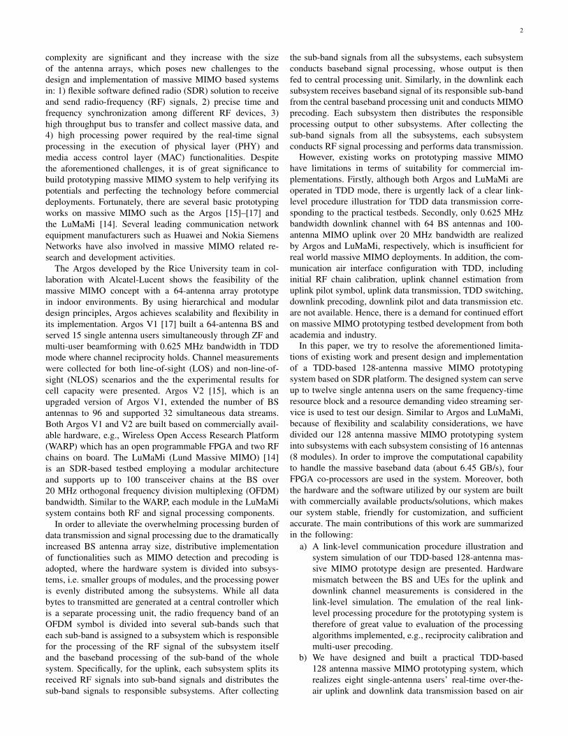
Link-level simulation of the TDD-based 128 antenna mas-sive MIMO system is presented in this section. Firstly, wegive the simulation parameters including system configuration,channel parameters and resource grids of UEs. Then weshow the system block diagram which illustrates the link-level transmission procedure in detail. Numerical results arepresented at last.
A. Simulation Parameters
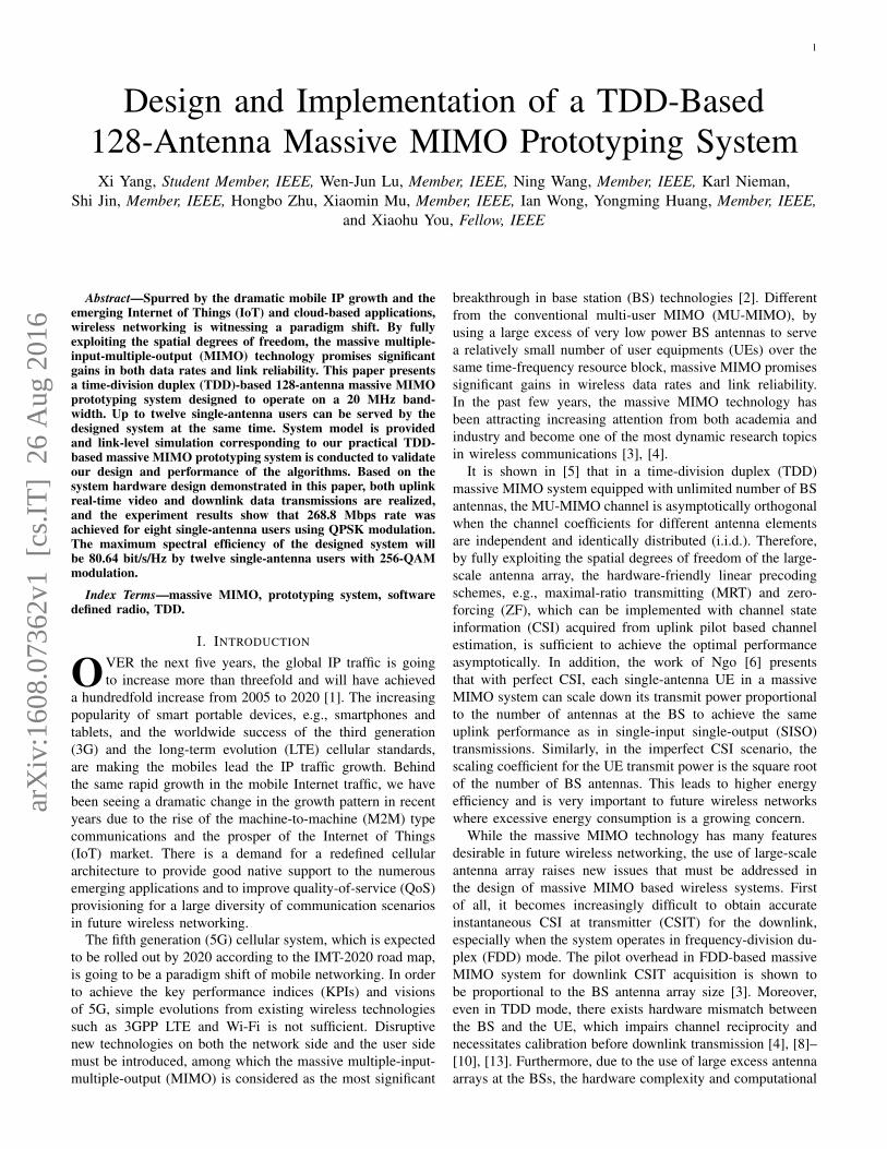
The simulation is conducted by using system and environ-ment settings similar to the LTE cellular systems, which setssimulation parameters as shown in Table I. Both the OFDMand frequency orthogonal pilots are employed in the link-levelsimulation, the time-frequency resource grids of the 12 single-antenna users are illustrated in Fig. 3 which are consistent withthe descriptions in Section II with each sub-band containing 12subcarriers. In addition, the simulation is conducted for spatialchannel model (SCM) [21] and the settings of the channelmodel are given in Table II.
TABLE ISYSTEM SIMULATION PARAMETERS
Parameter Variable Value# of BS antennas M 128# of single-antenna UEs K 12Bandwidth W 20MHzSampling Rate Fs 30.72MS/sFFT size NFFT 2048# of used subcarriers ND
sc 1200OFDM symbols per slot Ns 7CP Type - NormalModulation - BPSK, 4/16/64-QAM
B. Link-level Procedure
According to the system model and simulation parametersgiven above, the block diagram of the TDD-based massiveMIMO system in link-level simulation is shown in Fig. 4.
In the uplink, if current OFDM symbol is used for uplinkpilot transmission, then pilot symbols (QPSK modulated) are
.
.
11
10
9
8
7
6
5
4
3
2
1
0
.
.
TimeTime
Freq
uen
cy(1
20
0 s
ub
carr
iers
)Fr
equ
ency
(12
00
su
bca
rrie
rs)
Resource element
Resource block
12
su
bca
rrie
rs1
2 s
ub
carr
iers
One frame(10 ms)
#0 #1 #2 #3 #4 #5 #6 #7 #8 #9
One subframe(1 ms)
Slot 0 Slot 1
UE 0UE 0
Uplink Pilot
Preserved
Uplink DataDownlink Pilot
Downlink Data
.
.
11
10
9
8
7
6
5
4
3
2
1
0
.
.
TimeTime
Resource element
Resource block
12
su
bca
rrie
rs1
2 s
ub
carr
iers
UE 11UE 11……
.
.
11
10
9
8
7
6
5
4
3
2
1
0
.
.
TimeTime
Resource element
Resource block
12
su
bca
rrie
rs1
2 s
ub
carr
iers
UE 1UE 1
Fig. 3. The time-frequency resource grids of twelve single-antenna UEs.Frequency orthogonal pilots are employed for the twelve single-antenna UEsand the number of subcarriers in one subband is 12.
TABLE IISCM CHANNEL MODEL PARAMETERS.
Parameter ValueChannel model SCMScenario suburban macro# of BS antennas 128# of UE antennas 1# of UEs 12Antenna spacing at BS 0.5λ# of multipath 6Delay sampling interval 1
30.72×10⁶
DataGeneration
PilotGeneration
QAMModulation
PilotInsertion
OFDMMod.
QAMDemodulation
LMMSEdetector
OFDM Demod.RF Calibration
SynchronizationData
RecoveryChannel
estimation
DataGeneration
QAMModulation
WirelessChannel
OFDMMod.
QAMDemodulation
ChannelEqualization
OFDM Demod.Data
RecoveryChannel
Estimation
Precoding
Downlink
Uplink
WirelessChannel
UE
BS
UE
BS
...
...
Fig. 4. The system block diagram of the TDD-based 128 antenna massiveMIMO system in link-level simulation. Top: uplink pilot/data transmission.Bottom: downlink pilot/data transmission.
generated and mapped into resource elements in accordancewith the time-frequency resource grids in Fig. 3. Otherwise,raw data bits are generated and QAM modulated, after whichthe acquired data symbols are mapped into resource blocksin accordance with the time-frequency resource grid. In theOFDM modulation, IFFT and cyclic prefixing (CP) are carried

6
out. Either the pilot or data OFDM symbol is then transmittedby the UE through the SCM channel. At the base stationend, synchronization with the UEs is done by PSS. OFDMdemodulation, i.e. FFT and CP removal are then carried out,followed by reciprocity calibration, LS channel estimationand joint LMMSE detection. QAM demodulation is thenconducted, which recovers the raw data bits and also calculatesbit error rate (BER).
For the downlink, it is the inverse process of the uplink.First of all, raw data bits for the single-antenna users aregenerated at the BS. After QAM modulation, precoding (basedon the uplink channel estimate) and OFDM modulation,the users’ OFDM modulated signals are transmitted by themassive MIMO base station over the SCM channel. It isworth noting that we assume the channel is quasi-static withina time slot, and thus the SCM channel coefficients duringone time slot does not change except for the transposingoperation between the uplink and the downlink. At the UEside, similar to the BS in the uplink, OFDM demodulation,LS channel estimation, maximum-ratio combining and QAMdemodulation are conducted in sequential. Note that thereis no specific synchronization in the downlink because thesynchronization has been well achieved in the uplink due tothe assumption of time alignment in UEs for simplicity.
Besides, according to the practical measurement, we modelthe hardware mismatch impairments as complex multiplicativecoefficients on subcarriers with unit norm and random phasesfor both BS and UEs antennas. Reciprocity calibration iscarried out in the initialization of the simulation as laterthe prototyping system does. It is worthy to point out thatwe adopt Pre-precoding Calibration (Pre-Cal) in our link-level simulation, which is in consistency with our prototypingsystem design while having little difference with the systemmodel. As discussed in [22], the reciprocity can be carriedout either before or after precoding. These two scenarios arereferred to as Pre-Cal and Post-precoding Calibration (Post-Cal), respectively. However, the study in [9] points out thatthe Pre-Cal scheme outperforms Post-Cal, which motivatesthe use of the Pre-Cal approach in the simulation and in ourprototyping system as well.
C. Numerical Results
In the simulation results presented in the following, theimpacts of reciprocity calibration under different precodingmatrices, the BER for different users with different modula-tion, and the throughput of the system are investigated.
Fig. 5 shows the impact of reciprocity calibration both inthe uplink and the downlink data transmission under differentprecoding schemes. As can be observed, reciprocity calibrationhas significant impact on downlink data transmission, but hasnegligible impact on the uplink. Regardless of whether ornot introducing the reciprocity calibration, the BER of all thesingle-antenna users is 10−4 at SNR = 4dB in the uplink.However, the performance of downlink severely degradeswithout reciprocity calibration no matter MRT or LMMSEprecoding is employed. This is because the effective uplinkchannel, which contains the hardware mismatch between the
0 1 2 3 4 5 610
−7
10−6
10−5
10−4
10−3
10−2
SNR(dB)
BE
R
128x12 QPSK Uplink
UE0UE1UE2UE3UE4UE5UE6UE7UE8UE9UE10UE11
0 5 10 15 20
10−0.42
10−0.41
10−0.4
10−0.39
10−0.38
SNR(dB)
BE
R
128x12 QPSK Downlink
UE0UE1UE2UE3UE4UE5UE6UE7UE8UE9UE10UE11
0 1 2 3 4 5 610
−7
10−6
10−5
10−4
10−3
10−2
SNR(dB)
BE
R
128x12 QPSK Uplink
UE0UE1UE2UE3UE4UE5UE6UE7UE8UE9UE10UE11
0 5 10 15 2010
−8
10−6
10−4
10−2
100
SNR(dB)
BE
R
128x12 QPSK Downlink
UE0UE1UE2UE3UE4UE5UE6UE7UE8UE9UE10UE11
MRT
MRT
LMMSE
LMMSE
Fig. 5. The impact of reciprocity calibration under different precoding matrixwhen M = 128, K = 12 and QPSK is used for the 12 single-antennausers. Top: The BER of uplink(left)/downlink(right) data transmission withreciprocity calibration. Bottom: The BER of uplink(left)/downlink(right) datatransmission without reciprocity calibration.
SNR(dB)0 5 10 15 20
BE
R
10-7
10-6
10-5
10-4
10-3
10-2
10-1
100128x12 Uplink
UE0UE1UE2UE3UE4UE5UE6UE7UE8UE9UE10UE11
SNR(dB)0 5 10 15 20
BE
R
10-7
10-6
10-5
10-4
10-3
10-2
10-1
100128x12 Downlink
UE0UE1UE2UE3UE4UE5UE6UE7UE8UE9UE10UE11
BPSK
QPSK
QPSK16QAM 16QAM
64QAM
64QAM
BPSK
Fig. 6. The BER for different users with different modulation in uplink anddownlink for M = 128 and K = 12. BPSK is used for UE0-2, QPSK isused for UE3-5, 16-QAM is used for UE6-8, 64-QAM is used for UE9-11and reciprocity calibration is also considered. Left: uplink data transmission.Right: downlink data transmission.
BS’ RX chains and the UEs’ TX chains is well estimatedby uplink pilot and the data transmitted from multiuser arejointly processed at BS by making full use of the estimatedeffective channel coefficients. Nevertheless, the channel reci-procity in TDD mode is destroyed by the hardware mismatchbetween BS’ TX chains and BS’ RX chains. The precodingmatrix constructed from the estimated effective channel cannoteffectively inhibit the interference in the downlink whichresults in degraded performance. In addition, with reciprocitycalibration, LMMSE precoding outperforms MRT in downlinkdata transmission.
Fig. 6 and Fig. 7 show the BER and throughput for differentusers for different modulation schemes. In Fig. 6, the uplinkdata transmission outperforms the downlink due to the jointprocessing at the BS. By comparing with Fig. 7, it is observed

7
SNR(dB)0 5 10 15 20
Mbp
s
16.78
16.79
16.8
17128x12 Uplink
UE0UE1UE2Theory
SNR(dB)0 5 10 15 20
Mbp
s
33.3
33.43
33.6
33.78
UE3UE4UE5Theory
SNR(dB)0 5 10 15 20
Mbp
s
49
56
63
70
UE6UE7UE8Theory
SNR(dB)0 5 10 15 20
Mbp
s
52.5
70
87.5
105
UE9UE10UE11Theory
SNR(dB)0 5 10 15 20
Mbp
s
15.4
16.1
16.8
17.5128x12 Downlink
UE0UE1UE2Theory
SNR(dB)0 5 10 15 20
Mbp
s
28
31.5
35
UE3UE4UE5Theory
SNR(dB)0 5 10 15 20
Mbp
s
35
52.5
70
UE6UE7UE8Theory
SNR(dB)0 5 10 15 20
Mbp
s
52.5
70
87.5
105
UE9UE10UE11Theory
BPSK
QPSK
16QAM
QPSK
BPSK
64QAM
16QAM
64QAM
Fig. 7. Throughput of users when M = 128 and K = 12. The theoreticalthroughput of different QAM modulation under 20MHz bandwidth withOFDM utilized is presented as a baseline for different users, and BPSK isused for UE0-2, QPSK is used for UE3-5, 16-QAM is used for UE6-8, 64-QAM is used for UE9-11. Left: uplink data transmission. Right: downlinkdata transmission with reciprocity calibration.
that higher modulation order results in worse BER perfor-mance but higher throughput as well. Consequently, there isa tradeoff between system throughput and BER performance.In our prototyping system, in order to acquire better BER tosupport video streaming application in the absence of channelcoding, we choose QPSK for all users in the uplink, whichcan achieve 268.8Mbps peak rate for twelve users. As for 64-QAM, up to 1.2Gbps peak rate can be achieved over a 20MHzbandwidth for twelve users at high SNR.
IV. SYSTEM DESIGN AND EXPERIMENT SETUP
In this section, we present the hardware design of our TDD-based 128 antenna massive MIMO prototyping system includ-ing system architecture, the description of major componentsand experiment setup. Uplink and downlink data transmissionprocedures along with hardware devices are also discussed indetail.
A. System Architecture and Experiment Deployment
1) Overview of the system architecture: The system archi-tecture of our TDD-based 128 antenna massive MIMO proto-typing system based on software defined radio platform (i.e.,USRP-RIO manufactured by National Instruments) combiningthe clock distribution module and the high data throughput PXIsystem is showed in Fig. 8.
A brief introduction of all the hardware components in-volved in the system block diagram in Fig. 8 is given in thefollowing.
• PXIe-1085 chassis: 3U PXI Express chassis with 18 slots,including 16 hybrid slots and one PXI Express systemtiming slot. Each hybrid slot has a bandwidth of 4 GB/sand can be connected with an NI 2943R through PXIe-8374.
• PXIe-8135: NI PXIe-8135 is a high-performance embed-ded controller based on Intel Core i7-3610QE processorwith 2.3 GHz baseband frequency, 3.3 GHz quad-coreCPU and dual-channel 1,600 MHz DDR3 memory.
• PXIe-8384/PXIe-8381: x8 Gen 2 cabled PCI Expressinterface suite, used to connect PXI chassis for thepurpose of converging data from sub PXIe-1085 chassisto main PXIe-1085 chassis.
• PXIe-6674T: Timing and trigger sync module with on-board highly stable 10 MHz OCXO (sensitivity of 50ppb). This module is used to generate clock signal andenlarge trigger signal, which can be then routed amongmultiple devices such as PXI chassis and USRP RIOsto realize precise synchronization of timing and triggersignals across the whole system.
• PXIe-7976R: DSP-focused Xilinx Kintex-7 FPGA co-processor, used to help CPU process baseband data suchas channel estimation and MIMO detector.
• PXIe-8374: MXIe x4 Cabled PCIe interface card, canbe used to connect NI 2943R and the PXI chassis fordata exchange with a real-time data transfer bandwidthup to 200 MHz and the maximum data transfer rate is800 MB/s.
• NI 2943R: SDR nodes of USRP RIO series, consists ofa programmable FPGA (Xilinx Kintex-7) and two RFtransceivers of 40MHz bandwidth with center frequencyto be configured in the range of 1.2-6GHz, the maximumtransmitting power is 15 dBm.
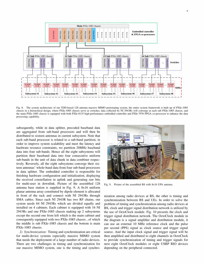
According to Fig. 8, the entire system framework is built upof PXIe-1085 chassis in a hierarchical design, where PXIe-1085 chassis serve as switches. Data collected by USRPRIOs will converge at each sub PXIe-1085 chassis, whichcan connect up to 16 USRP-RIO to construct a MIMO ofsize 32×32. Then each sub PXIe-1085 chassis will aggregatedata to the main PXIe-1085 chassis through PXIe-8384 andPXIe-8381. The main PXIe-1085 chassis is equipped with notonly the PXIe-8135 high-performance embedded controller,but also the PXIe-7976 FPGA co-processor to enhance thedata processing capability.
Besides, as indicated in the diagram, the idea of subsystemis used in our massive MIMO system to aggregate and transferbaseband data efficiently. There are a total of eight subsys-tems in our 128-antenna massive MIMO system with eachsubsystem containing eight USRP RIOs, i.e. sixteen antennas.In each subsystem, one of the eight USRP RIOs serves asdata combiner and another serves as data splitter. All sixteenantennas’ whole band (i.e. 20MHz) baseband data will begrouped into consecutive data chunks where baseband data arealigned with antenna index in data combiner and data splitter,except the difference that in data combiner, baseband data areaggregated in current subsystem and will be distributed to sub-band processors for channel estimation and MIMO detection
8
Swtiches
SDRs
Main PXIe-1085 chassis
PX
Ie-8135
PX
Ie-83
84
PX
Ie-79
76R
PX
Ie-66
74T
PX
Ie-83
84
PX
Ie-83
84
Reserv
ed
PX
Ie-79
76R
PX
Ie-79
76R
PX
Ie-83
84
PX
Ie-79
76R
Reserv
ed
Reserv
ed
Reserv
ed
Reserv
ed
Reserv
ed
Reserv
ed
Reserv
ed
NI 2943R
2*2 #16
#1 Sub PXIe-1085 chassis
PX
Ie-8381
PX
Ie-83
74
PX
Ie-83
74
PX
Ie-83
74
PX
Ie-83
74
……
NI 2943R
2*2 #1 …NI 2943R
2*2 #8
NI 2943R
2*2 #9 …
Subsystem #1 Subsystem #2
NI 2943R
2*2 #17 …
#2 Sub PXIe-1085 chassis
PX
Ie-8381
PX
Ie-83
74
PX
Ie-83
74
PX
Ie-83
74
PX
Ie-83
74
……
NI 2943R
2*2 #24
NI 2943R
2*2 #25
NI 2943R
2*2 #32…
Subsystem #3 Subsystem #4
NI 2943R
2*2 #33 …
#3 Sub PXIe-1085 chassis
PX
Ie-8381
PX
Ie-83
74
PX
Ie-83
74
PX
Ie-83
74
PX
Ie-83
74
……
NI 2943R
2*2 #40
NI 2943R
2*2 #41
NI 2943R
2*2 #48…
Subsystem #5 Subsystem #6
#4 Sub PXIe-1085 chassis
PX
Ie-8381
NI 2943R
2*2 #49 …
PX
Ie-83
74
PX
Ie-83
74
PX
Ie-83
74
PX
Ie-83
74
……
NI 2943R
2*2 #56
NI 2943R
2*2 #57
NI 2943R
2*2 #64…
Subsystem #7 Subsystem #8
Embedded controller
& FPGA co-processors
Fig. 8. The system architecture of our TDD-based 128 antenna massive MIMO prototyping system, the entire system framework is built up of PXIe-1085chassis in a hierarchical design, where PXIe-1085 chassis serve as switches, data collected by NI 2943Rs will converge at each sub PXIe-1085 chassis, andthe main PXIe-1085 chassis is equipped with both PXIe-8135 high-performance embedded controller and PXIe-7976 FPGA co-processor to enhance the dataprocessing capability.
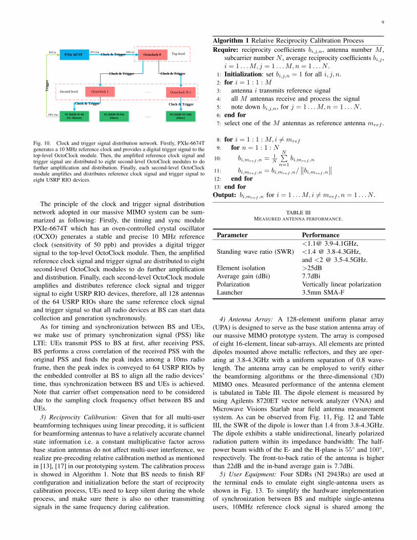
subsequently, while in data splitter, precoded baseband dataare aggregated from sub-band processors and will then bedistributed to sixteen antennas in current subsystem. Note thateach sub-band processor is related to a sub-band partition, inorder to improve system scalability and meet the latency andhardware resource constraints, we partition 20MHz basebanddata into four sub-bands. Hence all the eight subsystems willpartition their baseband data into four consecutive uniformsub-bands in the unit of data chunk in data combiner respec-tively. Reversely, all the eight subsystems converge their six-teen antennas’ whole-band data from four sub-band processorsin data splitter. The embedded controller is responsible forfinishing hardware configuration and initialization, displayingthe received constellation in uplink and generating raw bitsfor multi-user in downlink. Picture of the assembled 128antenna base station is supplied in Fig. 9. A 8x16 uniformplanar antenna array constituted by dipole element is allocatedin front of the rack and connect with NI 2943Rs throughSMA cables. Since each NI 2943R has two RF chains, oursystem needs 64 NI 2943Rs which are divided equally andinstalled on 4 cabinets. Each cabinet is equipped with 16 NI2943Rs and one PXIe-1085 chassis making up 2 subsystemsexcept the second one from left which is the main cabinet andconsequently equipped with two PXIe-1085 chassis , of whichthe middle is sub PXIe-1085 chassis and the bottom is mainPXIe-1085 chassis.
2) Synchronization: Timing and synchronization are criticalfor multi-device systems especially massive MIMO systemthat needs the deployment of a large number of radio devices.There are two challenges in timing and synchronization forour massive MIMO system, one is the timing and synchro-
Fig. 9. Picture of the assembled BS with 8x16 UPA antenna.
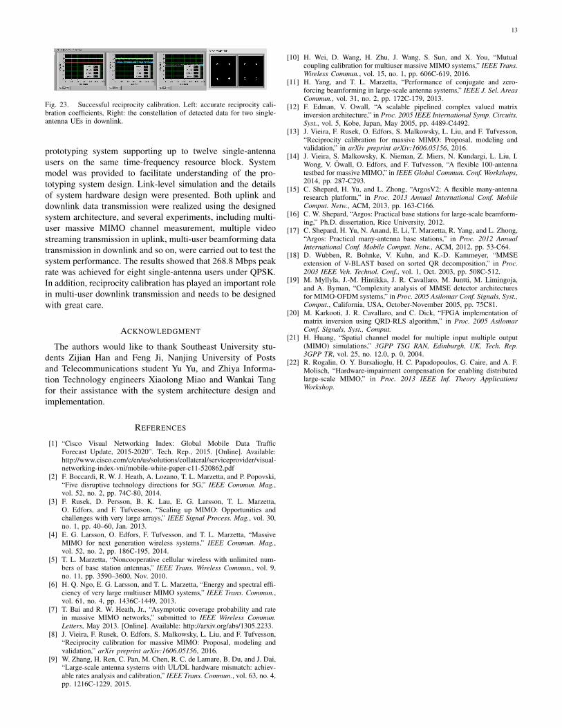
nization among radio devices at BS, the other is timing andsynchronization between BS and UEs. In order to solve theproblem of timing and synchronization among radio devices atBS, clock and trigger signal distribution network is utilized bythe use of OctoClock module. Fig. 10 presents the clock andtrigger signal distribution network. The OctoClock module inthe diagram is a signal amplifier and distribution module, itcan use an external 10 MHz reference clock and the pulseper second (PPS) signal as clock source and trigger signalsource. And the input clock signal and trigger signal will bethen amplified and distributed to eight channels in OctoClockto provide synchronization of timing and trigger signals fornext eight OctoClock modules or eight USRP RIO devicesdepending on the peripheral connected.
9
PXIe -6674T Octoclock 0
Octoclock 1 Octoclock N-1
PFI Out PPS InPFI In
PPS Out
……
NI 2943R #1-#8
(#1: Master)
NI 2943R #9-#16
(Slave)
NI 2943R #57-#64
(Slave)……
Tri
gg
er
Clock & Trigger
Clock & Trigger Clock & Trigger
Clock & Trigger Clock & Trigger
Top level
Second level
Fig. 10. Clock and trigger signal distribution network. Firstly, PXIe-6674Tgenerates a 10 MHz reference clock and provides a digital trigger signal to thetop-level OctoClock module. Then, the amplified reference clock signal andtrigger signal are distributed to eight second-level OctoClock modules to dofurther amplification and distribution. Finally, each second-level OctoClockmodule amplifies and distributes reference clock signal and trigger signal toeight USRP RIO devices.
The principle of the clock and trigger signal distributionnetwork adopted in our massive MIMO system can be sum-marized as following: Firstly, the timing and sync modulePXIe-6674T which has an oven-controlled crystal oscillator(OCXO) generates a stable and precise 10 MHz referenceclock (sensitivity of 50 ppb) and provides a digital triggersignal to the top-level OctoClock module. Then, the amplifiedreference clock signal and trigger signal are distributed to eightsecond-level OctoClock modules to do further amplificationand distribution. Finally, each second-level OctoClock moduleamplifies and distributes reference clock signal and triggersignal to eight USRP RIO devices, therefore, all 128 antennasof the 64 USRP RIOs share the same reference clock signaland trigger signal so that all radio devices at BS can start datacollection and generation synchronously.
As for timing and synchronization between BS and UEs,we make use of primary synchronization signal (PSS) likeLTE: UEs transmit PSS to BS at first, after receiving PSS,BS performs a cross correlation of the received PSS with theoriginal PSS and finds the peak index among a 10ms radioframe, then the peak index is conveyed to 64 USRP RIOs bythe embedded controller at BS to align all the radio devices’time, thus synchronization between BS and UEs is achieved.Note that carrier offset compensation need to be considereddue to the sampling clock frequency offset between BS andUEs.
3) Reciprocity Calibration: Given that for all multi-userbeamforming techniques using linear precoding, it is sufficientfor beamforming antennas to have a relatively accurate channelstate information i.e. a constant multiplicative factor acrossbase station antennas do not affect multi-user interference, werealize pre-precoding relative calibration method as mentionedin [13], [17] in our prototyping system. The calibration processis showed in Algorithm 1. Note that BS needs to finish RFconfiguration and initialization before the start of reciprocitycalibration process, UEs need to keep silent during the wholeprocess, and make sure there is also no other transmittingsignals in the same frequency during calibration.
Algorithm 1 Relative Reciprocity Calibration ProcessRequire: reciprocity coefficients bi,j,n, antenna number M ,
subcarrier number N , average reciprocity coefficients bi,j ,i = 1 . . .M, j = 1 . . .M, n = 1 . . . N .
1: Initialization: set bi,j,n = 1 for all i, j, n.2: for i = 1 : 1 :M3: antenna i transmits reference signal4: all M antennas receive and process the signal5: note down bi,j,n, for j = 1 . . .M, n = 1 . . . N .6: end for7: select one of the M antennas as reference antenna mref .
8: for i = 1 : 1 :M, i 6= mref
9: for n = 1 : 1 : N
10: bi,mref ,n = 1N
N∑n=1
bi,mref ,n
11: bi,mref ,n = bi,mref ,n/∥∥bi,mref ,n
∥∥12: end for13: end forOutput: bi,mref ,n for i = 1 . . .M, i 6= mref , n = 1 . . . N .
TABLE IIIMEASURED ANTENNA PERFORMANCE.
Parameter Performance
Standing wave ratio (SWR)<1.1@ 3.9-4.1GHz,<1.4 @ 3.8-4.3GHz,and <2 @ 3.5-4.5GHz.
Element isolation >25dBAverage gain (dBi) 7.7dBiPolarization Vertically linear polarizationLauncher 3.5mm SMA-F
4) Antenna Array: A 128-element uniform planar array(UPA) is designed to serve as the base station antenna array ofour massive MIMO prototype system. The array is composedof eight 16-element, linear sub-arrays. All elements are printeddipoles mounted above metallic reflectors, and they are oper-ating at 3.8-4.3GHz with a uniform separation of 0.8 wave-length. The antenna array can be employed to verify eitherthe beamforming algorithms or the three-dimensional (3D)MIMO ones. Measured performance of the antenna elementis tabulated in Table III. The dipole element is measured byusing Agilents 8720ET vector network analyzer (VNA) andMicrowave Visions Starlab near field antenna measurementsystem. As can be observed from Fig. 11, Fig. 12 and TableIII, the SWR of the dipole is lower than 1.4 from 3.8-4.3GHz.The dipole exhibits a stable unidirectional, linearly polarizedradiation pattern within its impedance bandwidth: The half-power beam width of the E- and the H-plane is 55◦ and 100◦,respectively. The front-to-back ratio of the antenna is higherthan 22dB and the in-band average gain is 7.7dBi.
5) User Equipment: Four SDRs (NI 2943Rs) are used atthe terminal ends to emulate eight single-antenna users asshown in Fig. 13. To simplify the hardware implementationof synchronization between BS and multiple single-antennausers, 10MHz reference clock signal is shared among the

10
-30
-20
-10
0
100
30
60
90
120
150
180
210
240
270
300
330
-40
-30
-20
-10
0
10
co-pol x-pol
-30
-20
-10
0
100
30
60
90
120
150
180
210
240
270
300
330
-40
-30
-20
-10
0
10
co-pol x-pol
-30
-20
-10
0
100
30
60
90
120
150
180
210
240
270
300
330
-40
-30
-20
-10
0
10
co-pol x-pol
-30
-20
-10
0
100
30
60
90
120
150
180
210
240
270
300
330
-40
-30
-20
-10
0
10
co-pol x-pol
(a) (b)
(c) (d)
Fig. 11. Radiation patterns of principal planes, H plane is parallel to theground and E plane is perpendicular to the ground, (a) H plane @3.8GHz,(b) E plane @3.8GHz, (c) H plane @4.1GHz, (d) E plane @4.1GHz.
3.5 4.0 4.5
6.5
7.0
7.5
8.0
8.5
Ga
in(d
Bi)
Frequency(GHz)
(a) (b)
Fig. 12. Measured gain and SWR frequency response characteristics of theantenna element, (a) gain, (b) standing wave ratio (SWR).
four SDRs. The details of hardware implementation for eachsingle-antenna user is provided in Fig. 4, where data gen-eration/recovery is implemented in embedded controller orcomputer and the rests are programmed in FPGA containedin SDRs.
6) Experiment Deployment: The experiments are conductedin a typical indoor office environment and its deployment isoffered in Fig. 14. The 128-element UPA with 1.2m heightis fixed near the chassis, and the eight horn antennas relatedto eight single-antenna users is placed at eight line-of-sight(LOS) points marked with 1, 2, . . . 8. A series of experimentsare carried out in the deployment including multi-user massiveMIMO channel measurement, multiple video streaming trans-mission in uplink, multi-user beamforming data transmissionin downlink and the performance of the relative reciprocitycalibration method. Experiment results are illustrated in Sec-
Fig. 13. User Equipments (UEs): eight single-antenna users.M
assiv
e M
IMO
An
ten
na
Arr
ay
Desk
Desk
Desk
Base Station
Gla
ss Pa
rtitio
n
Ch
assis
2m
5m
25cm
Ter
min
al
En
ds
(8 s
ing
le-a
nte
nn
a u
sers)
Line-of sight1
2
3
4
5
6
78
Win
dow
Do
or
Win
dow
Fig. 14. The measured environment and experiment deployment.
tion V.
B. Uplink Data Transmission Procedure
Fig. 15 presents the system block diagram related to hard-ware implementation for uplink. As is shown in the figure,for uplink, the RF signals acquired by 64 NI 2943Rs, i.e. 128antennas, firstly go through the 128 RF chains and performlow noise amplification, down conversion and ADC samplingand quantization, and then the high rate samples from ADC aresent to each NI 2943Rs’ FPGA for IQ imbalance correction,frequency shift correction, digital down sampling, OFDMdemodulation and reciprocity calibration, after that these ob-tained valid baseband data are aggregated and distributed tofour FPGA co-processors for further baseband processing bydata combiners through switches (e.g. PXIe-1085) in eachsubsystem. Finally, these recovered data are conveyed to theembedded controller by co-processors for further analysis anddisplay. In our prototyping system, the conversion accuracy ofADC is 12 bit, thus available data throughput per RF chain is50.4 MB/s (including I and Q). Each subsystem contains 16RF chains, therefore available data throughput per subsystem

11
RF ADCSynchronizat
ion
- CP,FFT,
-GuardCalibration
Data
Combiner
RF ADCSynchronizat
ion
- CP,FFT,
-GuardCalibration
USRP RIO (NI 2943R)
Channel
Estimation
Channel
Equalization
QAM
Demodulation
Other 7 USRP RIOs in
Subsystem
P2P FIFO...
#1 Subsystem of Base Station
(16 Antennas)
(Host) System parameters configuration, constellation and video display.
Embedded Controller (PXIe 8135)
#1 FPGA Co-Processor
#1
#2 Subsystem of Base Station
#8 Subsystem of Base Station
(16 Antennas)
#2 FPGA Co-Processor
#3 FPGA Co-Processor
#4 FPGA Co-Processor
…
Fig. 15. System block diagram related to hardware implementation for uplinkdata transmission at base station.
is 806.4 MB/s. There are total 8 subsystems connected withthe main switch thus the available data throughput in mainswitch will be about 6.5 GB/s.
C. Downlink Data Transmission Procedure
Downlink data transmission is a reverse process comparedwith uplink, the system block diagram related to hardware im-plementation for downlink is displayed in Fig. 16. For down-link, raw data bytes generated by the embedded controller arefirstly transferred to four co-processors for precoding, and thenthese precoded data are aggregated and distributed to each NI2943R by data splitters through switches (e.g. PXIe-1085) ineach subsystem. After OFDM modulation, digital up sampling,frequency shift correction and IQ imbalance correction in theFPGA of each NI 2943R, the high rate data bytes will beconveyed to each RF chain for digital to analog conversionand up conversion, and be sent to the air by antennas finally.
RF DACI、Q
CorrectionDUC
+CP,IFFT,
+GuardData
Splitter
RF DACI、Q
CorrectionDUC
+CP,IFFT,
+Guard
USRP RIO (NI 2943R)
PrecodingAdd PilotQAM
Modulation
Other 7 USRP RIOs in
Subsystem
P2P FIFO...
#1 Subsystem of Base Station
(16 Antennas)
(Host) System parameters configuration, raw bytes generation.
Embedded Controller (PXIe 8135)
#1 FPGA Co-Processor
#1
#2 Subsystem of Base Station
#8 Subsystem of Base Station
(16 Antennas)
#2 FPGA Co-Processor
#3 FPGA Co-Processor
#4 FPGA Co-Processor
Fig. 16. System block diagram related to hardware implementation fordownlink data transmission at base station.
V. EXPERIMENT RESULTS
By running the TDD-based 128-antenna massive MIMOprototyping system, experiments are carried out to test per-formance of our design. These experiments include multi-user massive MIMO channel measurement, multiple videostreaming transmission in the uplink, multi-user beamformingdata transmission in the downlink and the performance of therelative reciprocity calibration method. Experiment results arepresented and discussed in this section.
In order to measure the multi-user massive MIMO channel,pilots orthogonal in the frequency domain are transmitted by8 single-antenna users over the same time-frequency resourceblock after synchronization between the BS and the UEsusing a primary synchronization sequence. After receivingpilot signals, the BS estimates each user’s channel matrix usingLS channel estimation with local pilot sequence. Then themeasured channel matrices are further processed and analyzedto obtain results including channel time-domain impulse re-sponse, channel correlation matrix on the BS side and channelcorrelation matrix on the user side, which are demonstrated inFigs. 17 through 19. Fig. 17 shows that for user2 there isa distinctive planar wavefront with about 33 ns delay spreaddespite the little difference among different antennas, whichis the same as the other seven users’ implied by the averagedimpulse response. Combined with the sample rate of 30.72MS/s (i.e. 33 ns) for the 20 MHz bandwidth, the frequencyselectivity of the channel is not severe in current deployment.In addition, the distinctive planar wavefront of the right handside plot of Fig. 17 also verifies that the eight users are welltime aligned in the uplink. Fig. 18 and Fig. 19 show thechannel correlation matrix. For channel correlation matrix onthe BS side, signal strength is not concentrated on the diagonalline but on the border of squares. This is consistent with thegeometry of the antenna array used in our prototyping system.As for the UEs, signal strength is concentrated on the diagonalline as expected, which indicates that the single-antenna usersare independent.
Fig. 17. Left: time-domain impulse response of uplink channel for user2,the horizontal axis is delay (ns) and the vertical axis is antenna index, 128antennas are configured in BS. Right: time-domain impulse responses ofuplink channel for eight single-antenna users, averaged on 128 antennas.
As a proof of concept, according to the designed framestructure, real-time uplink and downlink data transmission testis conducted. In the transmission test, 8 single-antenna userstransmit pilot and video stream data to the 128-antenna BSwith transmit power 15 dBm. Based on the received pilot sig-nal, the BS performs channel estimation, MIMO detection and

12
20 40 60 80 100 120
20
40
60
80
100
120
5
10
15
20
25
30
Fig. 18. Channel correlation matrix on the BS side.
Fig. 19. Channel correlation matrix on the user side.
downlink precoding as described in system model in SectionII, as well as uplink and downlink transmission procedure inSection IV. The results of the test are showed in Fig. 20 andFig. 21. From Fig. 20, we can see QPSK indicated by theconstellation in the right monitor is employed in the uplink,and the base station successfully recovered the multiple videostreams and displayed them in the left monitor, which validatesthe 268.8Mbps peak rate achieved in the current bandwidth,modulation and user number configuration. Higher modulationorder can be configured flexibly if higher peak rate is needed.Fig. 21 shows the received signal spectrum and recovereddata by UEs in downlink. Each constellation represents asingle-antenna user and there are four single-antenna userspresented in the figure with three of them utilizing QPSK andone adopting 16-QAM (the other four users’ results are thesame and we do not present them for limited space). Thespectral efficiency we has achieved in current configurationis 16.8bit/s/Hz and the maximum 80.64bit/s/Hz can beobtained by the usage of 256-QAM and twelve single-antennausers.
In order to verify the performance of the relative reciprocitycalibration method, we take several trials by setting differentantennas as the reference antenna or keep UEs transmittingduring the calibration process. The results shown in Fig. 22
and Fig. 23 imply that when there is interference (e.g. UEsare transmitting signals) during the calibration process or theselected reference antenna is near the border of the antennaarray which leads to low SNR for the antennas in the oppositeside due to the array size, the reciprocity calibration coeffi-cients will be inaccurate and UEs can not recover the data theyreceived in downlink because of the large interference betweeneach other. Note that the accurate calibration coefficients onthe 1200 subcarriers (over a 20 MHz bandwidth) depicted inFig. 23 almost keep constant from the practical measurement,and it may be beneficial to design the waveform used forreciprocity calibration. Moreover, the geometry of antennaarray also needs to be considered deliberately in reciprocitycalibration methods.
Fig. 20. Test results for uplink multiple video streaming transmission, thebase station successfully recovered the multiple video streaming.
Fig. 21. Test results for downlink multi-user beamforming data transmission,the received signal spectrum and constellation are displayed by UEs.
Fig. 22. Unsuccessful reciprocity calibration. Left: reciprocity calibrationcoefficients when there is interference or the selected reference antenna isnear the border of the antenna array, Right: the constellation of detected datafor two single-antenna UEs in downlink.
VI. CONCLUSION
In this paper, we have presented the design and im-plementation of a TDD-based 128-antenna massive MIMO
13
Fig. 23. Successful reciprocity calibration. Left: accurate reciprocity cali-bration coefficients, Right: the constellation of detected data for two single-antenna UEs in downlink.
prototyping system supporting up to twelve single-antennausers on the same time-frequency resource block. Systemmodel was provided to facilitate understanding of the pro-totyping system design. Link-level simulation and the detailsof system hardware design were presented. Both uplink anddownlink data transmission were realized using the designedsystem architecture, and several experiments, including multi-user massive MIMO channel measurement, multiple videostreaming transmission in uplink, multi-user beamforming datatransmission in downlink and so on, were carried out to test thesystem performance. The results showed that 268.8 Mbps peakrate was achieved for eight single-antenna users under QPSK.In addition, reciprocity calibration has played an important rolein multi-user downlink transmission and needs to be designedwith great care.
ACKNOWLEDGMENT
The authors would like to thank Southeast University stu-dents Zijian Han and Feng Ji, Nanjing University of Postsand Telecommunications student Yu Yu, and Zhiya Informa-tion Technology engineers Xiaolong Miao and Wankai Tangfor their assistance with the system architecture design andimplementation.
REFERENCES
[1] “Cisco Visual Networking Index: Global Mobile Data TrafficForecast Update, 2015-2020”. Tech. Rep., 2015. [Online]. Available:http://www.cisco.com/c/en/us/solutions/collateral/serviceprovider/visual-networking-index-vni/mobile-white-paper-c11-520862.pdf
[2] F. Boccardi, R. W. J. Heath, A. Lozano, T. L. Marzetta, and P. Popovski,“Five disruptive technology directions for 5G,” IEEE Commun. Mag.,vol. 52, no. 2, pp. 74C-80, 2014.
[3] F. Rusek, D. Persson, B. K. Lau, E. G. Larsson, T. L. Marzetta,O. Edfors, and F. Tufvesson, “Scaling up MIMO: Opportunities andchallenges with very large arrays,” IEEE Signal Process. Mag., vol. 30,no. 1, pp. 40–60, Jan. 2013.
[4] E. G. Larsson, O. Edfors, F. Tufvesson, and T. L. Marzetta, “MassiveMIMO for next generation wireless systems,” IEEE Commun. Mag.,vol. 52, no. 2, pp. 186C-195, 2014.
[5] T. L. Marzetta, “Noncooperative cellular wireless with unlimited num-bers of base station antennas,” IEEE Trans. Wireless Commun., vol. 9,no. 11, pp. 3590–3600, Nov. 2010.
[6] H. Q. Ngo, E. G. Larsson, and T. L. Marzetta, “Energy and spectral effi-ciency of very large multiuser MIMO systems,” IEEE Trans. Commun.,vol. 61, no. 4, pp. 1436C-1449, 2013.
[7] T. Bai and R. W. Heath, Jr., “Asymptotic coverage probability and ratein massive MIMO networks,” submitted to IEEE Wireless Commun.Letters, May 2013. [Online]. Available: http://arxiv.org/abs/1305.2233.
[8] J. Vieira, F. Rusek, O. Edfors, S. Malkowsky, L. Liu, and F. Tufvesson,“Reciprocity calibration for massive MIMO: Proposal, modeling andvalidation,” arXiv preprint arXiv:1606.05156, 2016.
[9] W. Zhang, H. Ren, C. Pan, M. Chen, R. C. de Lamare, B. Du, and J. Dai,“Large-scale antenna systems with UL/DL hardware mismatch: achiev-able rates analysis and calibration,” IEEE Trans. Commun., vol. 63, no. 4,pp. 1216C-1229, 2015.
[10] H. Wei, D. Wang, H. Zhu, J. Wang, S. Sun, and X. You, “Mutualcoupling calibration for multiuser massive MIMO systems,” IEEE Trans.Wireless Commun., vol. 15, no. 1, pp. 606C-619, 2016.
[11] H. Yang, and T. L. Marzetta, “Performance of conjugate and zero-forcing beamforming in large-scale antenna systems,” IEEE J. Sel. AreasCommun., vol. 31, no. 2, pp. 172C-179, 2013.
[12] F. Edman, V. Owall, “A scalable pipelined complex valued matrixinversion architecture,” in Proc. 2005 IEEE International Symp. Circuits,Syst., vol. 5, Kobe, Japan, May 2005, pp. 4489-C4492.
[13] J. Vieira, F. Rusek, O. Edfors, S. Malkowsky, L. Liu, and F. Tufvesson,“Reciprocity calibration for massive MIMO: Proposal, modeling andvalidation,” in arXiv preprint arXiv:1606.05156, 2016.
[14] J. Vieira, S. Malkowsky, K. Nieman, Z. Miers, N. Kundargi, L. Liu, I.Wong, V. Owall, O. Edfors, and F. Tufvesson, “A flexible 100-antennatestbed for massive MIMO,” in IEEE Global Commun. Conf. Workshops,2014, pp. 287-C293.
[15] C. Shepard, H. Yu, and L. Zhong, “ArgosV2: A flexible many-antennaresearch platform,” in Proc. 2013 Annual International Conf. MobileComput. Netw., ACM, 2013, pp. 163-C166.
[16] C. W. Shepard, “Argos: Practical base stations for large-scale beamform-ing,” Ph.D. dissertation, Rice University, 2012.
[17] C. Shepard, H. Yu, N. Anand, E. Li, T. Marzetta, R. Yang, and L. Zhong,“Argos: Practical many-antenna base stations,” in Proc. 2012 AnnualInternational Conf. Mobile Comput. Netw., ACM, 2012, pp. 53-C64.
[18] D. Wubben, R. Bohnke, V. Kuhn, and K.-D. Kammeyer, “MMSEextension of V-BLAST based on sorted QR decomposition,” in Proc.2003 IEEE Veh. Technol. Conf., vol. 1, Oct. 2003, pp. 508C-512.
[19] M. Myllyla, J.-M. Hintikka, J. R. Cavallaro, M. Juntti, M. Limingoja,and A. Byman, “Complexity analysis of MMSE detector architecturesfor MIMO-OFDM systems,” in Proc. 2005 Asilomar Conf. Signals, Syst.,Comput., California, USA, October-November 2005, pp. 75C81.
[20] M. Karkooti, J. R. Cavallaro, and C. Dick, “FPGA implementation ofmatrix inversion using QRD-RLS algorithm,” in Proc. 2005 AsilomarConf. Signals, Syst., Comput.
[21] H. Huang, “Spatial channel model for multiple input multiple output(MIMO) simulations,” 3GPP TSG RAN, Edinburgh, UK, Tech. Rep.3GPP TR, vol. 25, no. 12.0, p. 0, 2004.
[22] R. Rogalin, O. Y. Bursalioglu, H. C. Papadopoulos, G. Caire, and A. F.Molisch, “Hardware-impairment compensation for enabling distributedlarge-scale MIMO,” in Proc. 2013 IEEE Inf. Theory ApplicationsWorkshop.


![Constructing Complete Radio Frequency Receiver for LTE TDD ... · to the 3G architecture [2]. The downlink capacity of at least ... Figure 4 demonstrates the return loss (S-Parameter)](https://img.pdfslide.us/doc/110x75/5e83a249fe00d8490167eac9/constructing-complete-radio-frequency-receiver-for-lte-tdd-to-the-3g-architecture.jpg)