Embed Size (px)
Citation preview
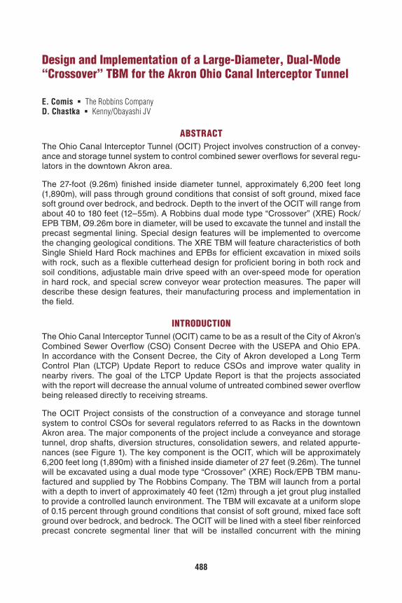
488
Design and Implementation of a Large-Diameter, Dual-Mode “Crossover” TBM for the Akron Ohio Canal Interceptor Tunnel
E. Comis The Robbins CompanyD. Chastka Kenny/Obayashi JV
ABSTRACTThe Ohio Canal Interceptor Tunnel (OCIT) Project involves construction of a convey-ance and storage tunnel system to control combined sewer overflows for several regu-lators in the downtown Akron area.
The 27-foot (9.26m) finished inside diameter tunnel, approximately 6,200 feet long (1,890m), will pass through ground conditions that consist of soft ground, mixed face soft ground over bedrock, and bedrock. Depth to the invert of the OCIT will range from about 40 to 180 feet (12–55m). A Robbins dual mode type “Crossover” (XRE) Rock/EPB TBM, Ø9.26m bore in diameter, will be used to excavate the tunnel and install the precast segmental lining. Special design features will be implemented to overcome the changing geological conditions. The XRE TBM will feature characteristics of both Single Shield Hard Rock machines and EPBs for efficient excavation in mixed soils with rock, such as a flexible cutterhead design for proficient boring in both rock and soil conditions, adjustable main drive speed with an over-speed mode for operation in hard rock, and special screw conveyor wear protection measures. The paper will describe these design features, their manufacturing process and implementation in the field.
INTRODUCTIONThe Ohio Canal Interceptor Tunnel (OCIT) came to be as a result of the City of Akron’s Combined Sewer Overflow (CSO) Consent Decree with the USEPA and Ohio EPA. In accordance with the Consent Decree, the City of Akron developed a Long Term Control Plan (LTCP) Update Report to reduce CSOs and improve water quality in nearby rivers. The goal of the LTCP Update Report is that the projects associated with the report will decrease the annual volume of untreated combined sewer overflow being released directly to receiving streams.
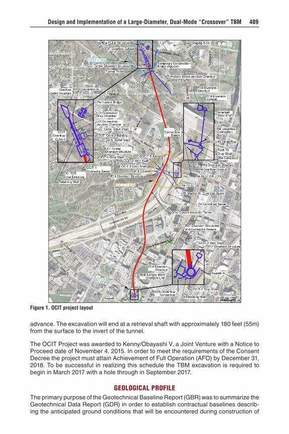
The OCIT Project consists of the construction of a conveyance and storage tunnel system to control CSOs for several regulators referred to as Racks in the downtown Akron area. The major components of the project include a conveyance and storage tunnel, drop shafts, diversion structures, consolidation sewers, and related appurte-nances (see Figure 1). The key component is the OCIT, which will be approximately 6,200 feet long (1,890m) with a finished inside diameter of 27 feet (9.26m). The tunnel will be excavated using a dual mode type “Crossover” (XRE) Rock/EPB TBM manu-factured and supplied by The Robbins Company. The TBM will launch from a portal with a depth to invert of approximately 40 feet (12m) through a jet grout plug installed to provide a controlled launch environment. The TBM will excavate at a uniform slope of 0.15 percent through ground conditions that consist of soft ground, mixed face soft ground over bedrock, and bedrock. The OCIT will be lined with a steel fiber reinforced precast concrete segmental liner that will be installed concurrent with the mining
Design and Implementation of a Large-Diameter, Dual-Mode “Crossover” TBM 489
advance. The excavation will end at a retrieval shaft with approximately 180 feet (55m) from the surface to the invert of the tunnel.
The OCIT Project was awarded to Kenny/Obayashi V, a Joint Venture with a Notice to Proceed date of November 4, 2015. In order to meet the requirements of the Consent Decree the project must attain Achievement of Full Operation (AFO) by December 31, 2018. To be successful in realizing this schedule the TBM excavation is required to begin in March 2017 with a hole through in September 2017.
GEOLOGICAL PROFILEThe primary purpose of the Geotechnical Baseline Report (GBR) was to summarize the Geotechnical Data Report (GDR) in order to establish contractual baselines describ-ing the anticipated ground conditions that will be encountered during construction of
Figure 1. OCIT project layout
490 Pressure Face TBM II
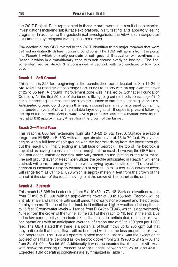
the OCIT Project. Data represented in these reports were as a result of geotechnical investigations including subsurface explorations, in situ testing, and laboratory testing programs. In addition to the geotechnical investigations, the GDR also incorporates data from the hydrological investigation performed.
The section of the GBR related to the OCIT identified three major reaches that were defined as distinctly different ground conditions. The TBM will launch from the portal into Reach 1 which primarily consists of soft ground. Excavation will continue into Reach 2 which is a transitionary zone with soft ground overlying bedrock. The final zone identified as Reach 3 is comprised of bedrock with two sections of low rock cover.
Reach 1—Soft GroundThis reach is 226 feet beginning at the construction portal located at Sta 11+24 to Sta 13+50. Surface elevations range from El 831 to El 885 with an approximate cover of 25 to 65 feet. A ground improvement zone was installed by Schnabel Foundation Company for the first 50 feet of the tunnel utilizing jet grout methods consisting of 140 each interlocking columns installed from the surface to facilitate launching of the TBM. Anticipated ground conditions in this reach consist primarily of silty sand containing interbedded layers of silt with a variable layer of glacial till deposits present following the top of the bedrock. Groundwater levels prior to the start of excavation were identi-fied at El 812 approximately 4 feet from the crown of the tunnel.
Reach 2—Mixed FaceThis reach is 600 feet extending from Sta 13+50 to Sta 19+50. Surface elevations range from El 868 to El 893 with an approximate cover of 45 to 70 feet. Excavation begins with a full face of soft ground with the bedrock rising from the invert through-out the reach until finally ending in a full face of bedrock. The top of the bedrock is depicted as having a consistent slope throughout the reach; however, the GBR identi-fies that configuration of bedrock may vary based on the jointing in the rock mass. The soft ground layer of Reach 2 emulates the profile anticipated in Reach 1 while the bedrock will consist primarily of shale with varying layers of siltstone. The top of the bedrock is identified as highly weathered at depths up to 10 feet. Groundwater levels will range from El 817 to El 820 which is approximately 4 feet from the crown of the tunnel at the start of the reach moving to at the crown of the tunnel at the end.
Reach 3—BedrockThis reach is 5,398 feet extending from Sta 19+50 to 73+48. Surface elevations range from El 893 to El. 992 with an approximate cover of 70 to 165 feet. Bedrock will be entirely shale and siltstone with small amounts of sandstone present and the potential for clay seams. The top of the bedrock is identified as highly weathered at depths up to 15 feet. Groundwater levels will range from El 842 to El 946, which is approximately 15 feet from the crown of the tunnel at the start of the reach to 115 feet at the end. Due to the low permeability of the bedrock, infiltration is not anticipated to impact excava-tion operations with an anticipated average infiltration rate of 50 to 100 gpm per 1,000 feet. The GBR stated that there is a potential of flush flows up to 200 gpm but that they anticipate that these flows will be brief and will become less present as excava-tion progresses. The TBM will operate in open mode in Reach 3 with the exception of two sections that are identified as low bedrock cover from Sta 19+50 to Sta 27+50 and from Sta 51+00 to Sta 56+50. Additionally, it was documented that the tunnel will exca-vate below the existing St. Vincent-St Mary’s landfill between Sta 26+00 and 33+00. Expected TBM operating conditions are summarized in Table 1.
Design and Implementation of a Large-Diameter, Dual-Mode “Crossover” TBM 491
TBM DESIGN FOR MIXED GROUND GEOLOGYA mixed ground condition consists of two or more geological formations, or the same rock formation with conspicuously different fracture intensity or weathering grades, with significantly different properties that will affect TBM operation. The mixed ground geology has been separated into 3 classes [1].
Class 1: Layered or banded ground formed by rock beddings, dykes, faults or shear zones
Class 2: Interface ground of soil and rock, or typically weathered materials above bedrock
Class 3: Mixed face with locked cobblestones, rock blocks with soil materials, or isolated spheroidal weathering stone mixed with a soft formation.
Studies have been carried out to analyze factors that contribute to fast machine advance in such conditions [2]. Although a strong correlation between TBM perfor-mance and a quality ground conditioning regime has been identified, the probable geology, hydrology and face pressures of a mixed ground project have a heavy impact on the TBM design:
Dress of cutterhead: disc cutters, scrapers, picks, bits, etc.
Opening ratio of cutterhead
Type of screw conveyors: ribbon or shafted
Quantity and length of screw conveyors
Abrasion-resistant cladding requirements: cutterhead, mixing chamber, mix-ing bars, screw conveyor flights and casing, etc.
Face pressure related design: pressure bulkhead, thrust ram sizing, articula-tion ram sizing, tail shield seals, main bearing seals, man-lock and tool-lock, breathable air design, air compressors, etc.
Ground conditioning foam, polymer and bentonite systems, air compressors, etc.
This paper will detail how these and other design features have been addressed on the Robbins TBM.
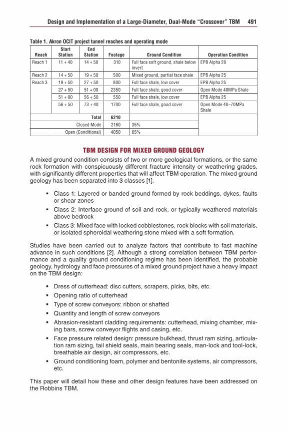
Table 1. Akron OCIT project tunnel reaches and operating mode
ReachStart
StationEnd
Station Footage Ground Condition Operation Condition
Reach 1 11 + 40 14 + 50 310 Full face soft ground, shale below invert
EPB Alpha 20
Reach 2 14 + 50 19 + 50 500 Mixed ground, partial face shale EPB Alpha 25
Reach 3 19 + 50 27 + 50 800 Full face shale, low cover EPB Alpha 25
27 + 50 51 + 00 2350 Full face shale, good cover Open Mode 40MPa Shale
51 + 00 56 + 50 550 Full face shale, low cover EPB Alpha 25
56 + 50 73 + 40 1700 Full face shale, good cover Open Mode 40–70MPa Shale
Total 6210
Closed Mode 2160 35%
Open (Conditional) 4050 65%
492 Pressure Face TBM II
Cutterhead Design
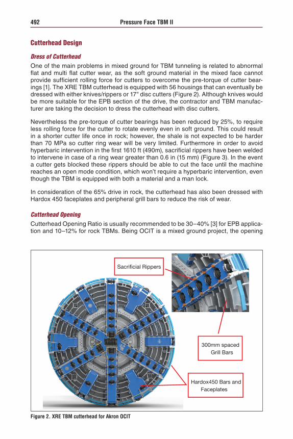
Dress of CutterheadOne of the main problems in mixed ground for TBM tunneling is related to abnormal flat and multi flat cutter wear, as the soft ground material in the mixed face cannot provide sufficient rolling force for cutters to overcome the pre-torque of cutter bear-ings [1]. The XRE TBM cutterhead is equipped with 56 housings that can eventually be dressed with either knives/rippers or 17" disc cutters (Figure 2). Although knives would be more suitable for the EPB section of the drive, the contractor and TBM manufac-turer are taking the decision to dress the cutterhead with disc cutters.
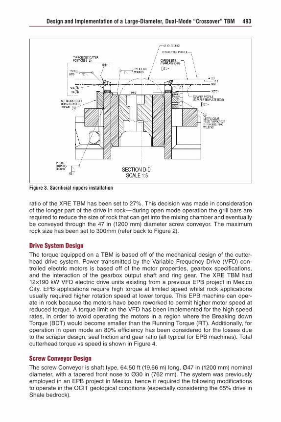
Nevertheless the pre-torque of cutter bearings has been reduced by 25%, to require less rolling force for the cutter to rotate evenly even in soft ground. This could result in a shorter cutter life once in rock; however, the shale is not expected to be harder than 70 MPa so cutter ring wear will be very limited. Furthermore in order to avoid hyperbaric intervention in the first 1610 ft (490m), sacrificial rippers have been welded to intervene in case of a ring wear greater than 0.6 in (15 mm) (Figure 3). In the event a cutter gets blocked these rippers should be able to cut the face until the machine reaches an open mode condition, which won’t require a hyperbaric intervention, even though the TBM is equipped with both a material and a man lock.
In consideration of the 65% drive in rock, the cutterhead has also been dressed with Hardox 450 faceplates and peripheral grill bars to reduce the risk of wear.
Cutterhead OpeningCutterhead Opening Ratio is usually recommended to be 30–40% [3] for EPB applica-tion and 10–12% for rock TBMs. Being OCIT is a mixed ground project, the opening
300mm spacedGrill Bars
Sacrificial Rippers
Hardox450 Bars andFaceplates
Figure 2. XRE TBM cutterhead for Akron OCIT
Design and Implementation of a Large-Diameter, Dual-Mode “Crossover” TBM 493
ratio of the XRE TBM has been set to 27%. This decision was made in consideration of the longer part of the drive in rock—during open mode operation the grill bars are required to reduce the size of rock that can get into the mixing chamber and eventually be conveyed through the 47 in (1200 mm) diameter screw conveyor. The maximum rock size has been set to 300mm (refer back to Figure 2).
Drive System DesignThe torque equipped on a TBM is based off of the mechanical design of the cutter-head drive system. Power transmitted by the Variable Frequency Drive (VFD) con-trolled electric motors is based off of the motor properties, gearbox specifications, and the interaction of the gearbox output shaft and ring gear. The XRE TBM had 12×190 kW VFD electric drive units existing from a previous EPB project in Mexico City. EPB applications require high torque at limited speed whilst rock applications usually required higher rotation speed at lower torque. This EPB machine can oper-ate in rock because the motors have been reworked to permit higher motor speed at reduced torque. A torque limit on the VFD has been implemented for the high speed rates, in order to avoid operating the motors in a region where the Breaking down Torque (BDT) would become smaller than the Running Torque (RT). Additionally, for operation in open mode an 80% efficiency has been considered for the losses due to the scraper design, seal friction and gear ratio (all typical for EPB machines). Total cutterhead torque vs speed is shown in Figure 4.
Screw Conveyor DesignThe screw Conveyor is shaft type, 64.50 ft (19.66 m) long, Ø47 in (1200 mm) nominal diameter, with a tapered front nose to Ø30 in (762 mm). The system was previously employed in an EPB project in Mexico, hence it required the following modifications to operate in the OCIT geological conditions (especially considering the 65% drive in Shale bedrock).
Figure 3. Sacrificial rippers installation

494 Pressure Face TBM II
Pump/Motor Drive AdditionThe conveyor is driven by two hydraulic radial piston motors with large displacement and high power density (up to 240 kW). Originally the installed capacity on the hydrau-lic power unit was 2×110 kW motor/pump units to reach a max theoretical speed of the screw of 6 rpm. However this original screw conveyor was designed as part of a double screw system with a ribbon-type screw conveyor as the first stage and the shaft-type as second stage, and to be operated in EPB mode only.
In consideration for the OCIT geology and the necessity to muck out shale bedrock, the single shaft-type screw conveyor required a much higher speed. The hydraulic power unit has been consequently upgraded to 5×110 kW, which brings the max theo-retical speed of the conveyor to 16 rpm at a limited torque of 232 kNm.
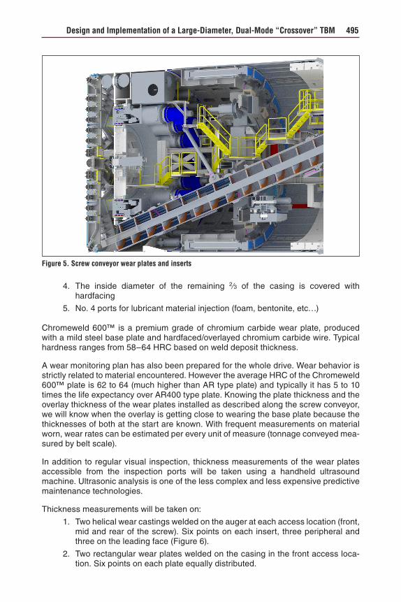
Wear ProtectionIn rock mode and mixed ground conditions, and to a lesser degree in EPB mode as well, the auger and the casings are in contact with abrasive material creating wear. The screw conveyor features the following characteristics to limit wear due to abrasion (refer to Figure 5):
1. The leading face of the front auger flight and the outside diameter is covered with welded-in wear plates, “inserts,” made of Chromeweld 600™ and hard-facing in a crosshatch pattern
2. The auger shaft is covered in hardfacing in a crosshatch pattern
3. The inside diameter of the casing is lined with welded 0.4 in (10 mm) thick Chromeweld 600™ for the first 1⁄3 of the casing
Figure 4. Drives torque-speed curve
Design and Implementation of a Large-Diameter, Dual-Mode “Crossover” TBM 495
4. The inside diameter of the remaining 2⁄3 of the casing is covered with hardfacing
5. No. 4 ports for lubricant material injection (foam, bentonite, etc…)
Chromeweld 600™ is a premium grade of chromium carbide wear plate, produced with a mild steel base plate and hardfaced/overlayed chromium carbide wire. Typical hardness ranges from 58–64 HRC based on weld deposit thickness.
A wear monitoring plan has also been prepared for the whole drive. Wear behavior is strictly related to material encountered. However the average HRC of the Chromeweld 600™ plate is 62 to 64 (much higher than AR type plate) and typically it has 5 to 10 times the life expectancy over AR400 type plate. Knowing the plate thickness and the overlay thickness of the wear plates installed as described along the screw conveyor, we will know when the overlay is getting close to wearing the base plate because the thicknesses of both at the start are known. With frequent measurements on material worn, wear rates can be estimated per every unit of measure (tonnage conveyed mea-sured by belt scale).
In addition to regular visual inspection, thickness measurements of the wear plates accessible from the inspection ports will be taken using a handheld ultrasound machine. Ultrasonic analysis is one of the less complex and less expensive predictive maintenance technologies.
Thickness measurements will be taken on:
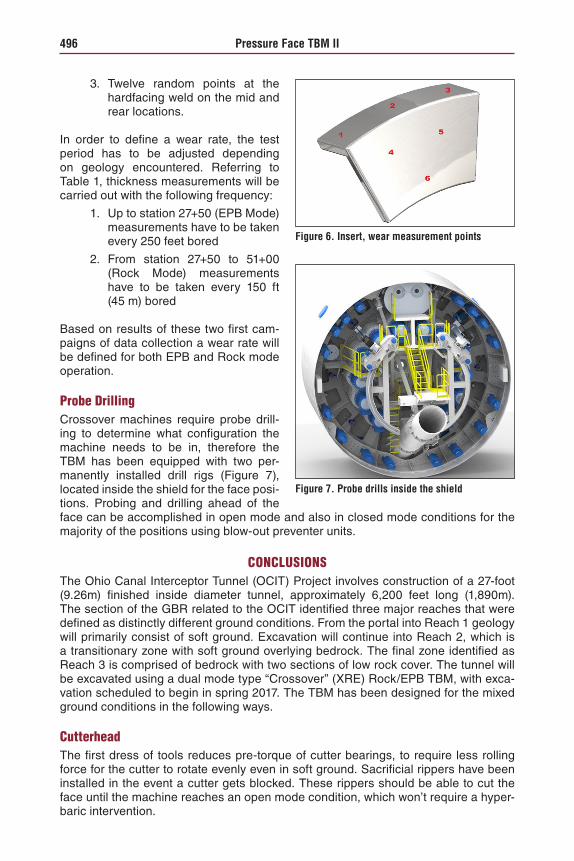
1. Two helical wear castings welded on the auger at each access location (front, mid and rear of the screw). Six points on each insert, three peripheral and three on the leading face (Figure 6).
2. Two rectangular wear plates welded on the casing in the front access loca-tion. Six points on each plate equally distributed.
Figure 5. Screw conveyor wear plates and inserts
496 Pressure Face TBM II
3. Twelve random points at the hardfacing weld on the mid and rear locations.
In order to define a wear rate, the test period has to be adjusted depending on geology encountered. Referring to Table 1, thickness measurements will be carried out with the following frequency:
1. Up to station 27+50 (EPB Mode) measurements have to be taken every 250 feet bored
2. From station 27+50 to 51+00 (Rock Mode) measurements have to be taken every 150 ft (45 m) bored
Based on results of these two first cam-paigns of data collection a wear rate will be defined for both EPB and Rock mode operation.
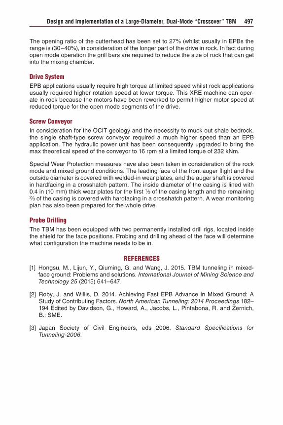
Probe DrillingCrossover machines require probe drill-ing to determine what configuration the machine needs to be in, therefore the TBM has been equipped with two per-manently installed drill rigs (Figure 7), located inside the shield for the face posi-tions. Probing and drilling ahead of the face can be accomplished in open mode and also in closed mode conditions for the majority of the positions using blow-out preventer units.
CONCLUSIONSThe Ohio Canal Interceptor Tunnel (OCIT) Project involves construction of a 27-foot (9.26m) finished inside diameter tunnel, approximately 6,200 feet long (1,890m). The section of the GBR related to the OCIT identified three major reaches that were defined as distinctly different ground conditions. From the portal into Reach 1 geology will primarily consist of soft ground. Excavation will continue into Reach 2, which is a transitionary zone with soft ground overlying bedrock. The final zone identified as Reach 3 is comprised of bedrock with two sections of low rock cover. The tunnel will be excavated using a dual mode type “Crossover” (XRE) Rock/EPB TBM, with exca-vation scheduled to begin in spring 2017. The TBM has been designed for the mixed ground conditions in the following ways.
CutterheadThe first dress of tools reduces pre-torque of cutter bearings, to require less rolling force for the cutter to rotate evenly even in soft ground. Sacrificial rippers have been installed in the event a cutter gets blocked. These rippers should be able to cut the face until the machine reaches an open mode condition, which won’t require a hyper-baric intervention.
Figure 6. Insert, wear measurement points
Figure 7. Probe drills inside the shield
Design and Implementation of a Large-Diameter, Dual-Mode “Crossover” TBM 497
The opening ratio of the cutterhead has been set to 27% (whilst usually in EPBs the range is (30–40%), in consideration of the longer part of the drive in rock. In fact during open mode operation the grill bars are required to reduce the size of rock that can get into the mixing chamber.
Drive SystemEPB applications usually require high torque at limited speed whilst rock applications usually required higher rotation speed at lower torque. This XRE machine can oper-ate in rock because the motors have been reworked to permit higher motor speed at reduced torque for the open mode segments of the drive.
Screw ConveyorIn consideration for the OCIT geology and the necessity to muck out shale bedrock, the single shaft-type screw conveyor required a much higher speed than an EPB application. The hydraulic power unit has been consequently upgraded to bring the max theoretical speed of the conveyor to 16 rpm at a limited torque of 232 kNm.
Special Wear Protection measures have also been taken in consideration of the rock mode and mixed ground conditions. The leading face of the front auger flight and the outside diameter is covered with welded-in wear plates, and the auger shaft is covered in hardfacing in a crosshatch pattern. The inside diameter of the casing is lined with 0.4 in (10 mm) thick wear plates for the first 1⁄3 of the casing length and the remaining 2⁄3 of the casing is covered with hardfacing in a crosshatch pattern. A wear monitoring plan has also been prepared for the whole drive.
Probe DrillingThe TBM has been equipped with two permanently installed drill rigs, located inside the shield for the face positions. Probing and drilling ahead of the face will determine what configuration the machine needs to be in.
REFERENCES[1] Hongsu, M., Lijun, Y., Qiuming, G. and Wang, J. 2015. TBM tunneling in mixed-
face ground: Problems and solutions. International Journal of Mining Science and Technology 25 (2015) 641–647.
[2] Roby, J. and Willis, D. 2014. Achieving Fast EPB Advance in Mixed Ground: A Study of Contributing Factors. North American Tunneling: 2014 Proceedings 182–194 Edited by Davidson, G., Howard, A., Jacobs, L., Pintabona, R. and Zernich, B.: SME.
[3] Japan Society of Civil Engineers, eds 2006. Standard Specifications for Tunneling-2006.