Embed Size (px)
Citation preview
Design and Implementation of a LabVIEW basedComputer Control for EPR Instrumentation
Diploma Thesis Defense
Matthias Kolja Miehl
October 22, 2010 at 2:30 pm
Milwaukee, Wisconsin, USAMedical College of WisconsinMACC Fund Research Center
Room L3075
LabVIEW based Computer Control
I Control and acquisition frameworkI Easily change hardwareI All experiments in one application
Figure: L-Band spectrometer at MCW’s Biophysics Research Department
2 / 72

LabVIEW based Computer Control
I Control and acquisition frameworkI Easily change hardwareI All experiments in one application
Figure: L-Band spectrometer at MCW’s Biophysics Research Department
3 / 72
Contents
1 Introduction
2 Concept
3 Implementation
4 Test
5 Summary and Vision
Contents
1 Introduction
2 Concept
3 Implementation
4 Test
5 Summary and Vision
LabVIEW based Computer Control
Introduction
Motivation
NeedMCW Research:
I New experiments
I Different spectrometers
I Changing Hardware
SituationUse of separate programs for
I each experiment,
I each spectrometer, and
I were rewritten for new instruments.
ProblemI Labor and time intensive tasks
I Reduction of actual research time
6 / 72

LabVIEW based Computer Control
Introduction
Motivation
NeedMCW Research:
I New experiments
I Different spectrometers
I Changing Hardware
SituationUse of separate programs for
I each experiment,
I each spectrometer, and
I were rewritten for new instruments.
ProblemI Labor and time intensive tasks
I Reduction of actual research time
7 / 72

LabVIEW based Computer Control
Introduction
Motivation
NeedMCW Research:
I New experiments
I Different spectrometers
I Changing Hardware
SituationUse of separate programs for
I each experiment,
I each spectrometer, and
I were rewritten for new instruments.
ProblemI Labor and time intensive tasks
I Reduction of actual research time8 / 72

LabVIEW based Computer Control
Introduction
Motivation
MotivationIncrease the actual research time by reducing redundancy.
I Experiment implementation
I Changing hardware
GoalVersatile framework:
I All experiments
I Every spectrometer
9 / 72

LabVIEW based Computer Control
Introduction
Motivation
MotivationIncrease the actual research time by reducing redundancy.
I Experiment implementation
I Changing hardware
GoalVersatile framework:
I All experiments
I Every spectrometer
10 / 72

LabVIEW based Computer Control
Introduction
Related Work
Existing ApproachesI WinEPR
I EWWin
I SpecMan4EPR
MCW’s RequirementsI Exchange of instruments
I Storing experiment settings
I Easy extension by customer
11 / 72
LabVIEW based Computer Control
Introduction
Related Work
Existing ApproachesI WinEPR
I EWWin
I SpecMan4EPR
MCW’s RequirementsI Exchange of instruments
I Storing experiment settings
I Easy extension by customer
12 / 72

Contents
1 Introduction
2 Concept
3 Implementation
4 Test
5 Summary and Vision
LabVIEW based Computer Control
Concept
Key Requirements
Key RequirementsI All experiments in one application
I Instruments easily exchangeable
I Maintainability and extendability
I 32 and 64-bit driver support
14 / 72

LabVIEW based Computer Control
Concept
Overall Structure
Core ofMain Appl.
InstrumentDriver
Instrument
...
...
64-bit
64 or 32-bit
Exp.GUI
...
Controls andIndicators
Logic
InternalData Flow
Inter-ProcessCommunication
Bus
HardwareAbstraction
Hardware
Figure: Overall application structure (concept)
15 / 72
Contents
1 Introduction
2 Concept
3 Implementation
4 Test
5 Summary and Vision

LabVIEW based Computer Control
Implementation
Overall Structure and Used Technologies
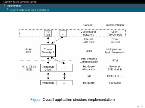
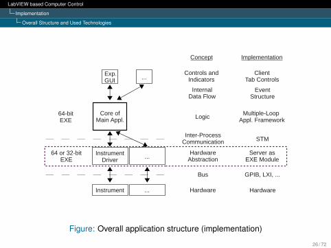
Core ofMain Appl.
InstrumentDriver
Instrument
ClientTab Controls
Multiple-Loop Appl. Framework
EventStructure
STM
Server asEXE Module
Hardware
...
...
64-bitEXE
64 or 32-bitEXE
Exp.GUI
...
Controls andIndicators
Logic
InternalData Flow
Inter-ProcessCommunication
Bus
HardwareAbstraction
Hardware
ImplementationConcept
GPIB, LXI, ...
Figure: Overall application structure (implementation)
17 / 72
LabVIEW based Computer Control
Implementation
Overall Structure and Used Technologies
Core ofMain Appl.
InstrumentDriver
Instrument
ClientTab Controls
Multiple-Loop Appl. Framework
EventStructure
STM
Server asEXE Module
Hardware
...
...
64-bitEXE
64 or 32-bitEXE
Exp.GUI
...
Controls andIndicators
Logic
InternalData Flow
Inter-ProcessCommunication
Bus
HardwareAbstraction
Hardware
ImplementationConcept
GPIB, LXI, ...
Figure: Overall application structure (implementation)
18 / 72
LabVIEW based Computer Control
Implementation
Overall Structure and Used Technologies
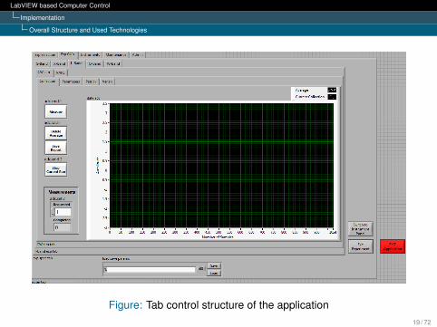
Figure: Tab control structure of the application19 / 72

LabVIEW based Computer Control
Implementation
Overall Structure and Used Technologies
Figure: Tab control structure as the operator sees it20 / 72
LabVIEW based Computer Control
Implementation
Overall Structure and Used Technologies
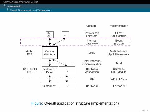
Core ofMain Appl.
InstrumentDriver
Instrument
ClientTab Controls
Multiple-Loop Appl. Framework
EventStructure
STM
Server asEXE Module
Hardware
...
...
64-bitEXE
64 or 32-bitEXE
Exp.GUI
...
Controls andIndicators
Logic
InternalData Flow
Inter-ProcessCommunication
Bus
HardwareAbstraction
Hardware
ImplementationConcept
GPIB, LXI, ...
Figure: Overall application structure (implementation)
21 / 72

LabVIEW based Computer Control
Implementation
Overall Structure and Used Technologies
Figure: Main program event handler loop
22 / 72
LabVIEW based Computer Control
Implementation
Overall Structure and Used Technologies
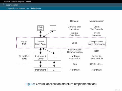
Core ofMain Appl.
InstrumentDriver
Instrument
ClientTab Controls
Multiple-Loop Appl. Framework
EventStructure
STM
Server asEXE Module
Hardware
...
...
64-bitEXE
64 or 32-bitEXE
Exp.GUI
...
Controls andIndicators
Logic
InternalData Flow
Inter-ProcessCommunication
Bus
HardwareAbstraction
Hardware
ImplementationConcept
GPIB, LXI, ...
Figure: Overall application structure (implementation)
23 / 72

LabVIEW based Computer Control
Implementation
Overall Structure and Used Technologies
Figure: Implementation of the main program’s parallel loop structure24 / 72

LabVIEW based Computer Control
Implementation
Overall Structure and Used Technologies
Core ofMain Appl.
InstrumentDriver
Instrument
ClientTab Controls
Multiple-Loop Appl. Framework
EventStructure
STM
Server asEXE Module
Hardware
...
...
64-bitEXE
64 or 32-bitEXE
Exp.GUI
...
Controls andIndicators
Logic
InternalData Flow
Inter-ProcessCommunication
Bus
HardwareAbstraction
Hardware
ImplementationConcept
GPIB, LXI, ...
Figure: Overall application structure (implementation)
25 / 72
LabVIEW based Computer Control
Implementation
Overall Structure and Used Technologies
Core ofMain Appl.
InstrumentDriver
Instrument
ClientTab Controls
Multiple-Loop Appl. Framework
EventStructure
STM
Server asEXE Module
Hardware
...
...
64-bitEXE
64 or 32-bitEXE
Exp.GUI
...
Controls andIndicators
Logic
InternalData Flow
Inter-ProcessCommunication
Bus
HardwareAbstraction
Hardware
ImplementationConcept
GPIB, LXI, ...
Figure: Overall application structure (implementation)
26 / 72

LabVIEW based Computer Control
Implementation
Overall Structure and Used Technologies
Core ofMain Appl.
InstrumentDriver
Instrument
ClientTab Controls
Multiple-Loop Appl. Framework
EventStructure
STM
Server asEXE Module
Hardware
...
...
64-bitEXE
64 or 32-bitEXE
Exp.GUI
...
Controls andIndicators
Logic
InternalData Flow
Inter-ProcessCommunication
Bus
HardwareAbstraction
Hardware
ImplementationConcept
GPIB, LXI, ...
Figure: Overall application structure (implementation)
27 / 72
LabVIEW based Computer Control
Implementation
Driver Management
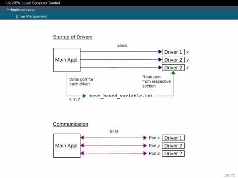
Startup of Drivers
Communication
Main Appl.
Driver 1
Driver 2
Driver 2
starts
text_based_variable.ini
Write port foreach driver
Read portfrom respectivesection
Main Appl.
Driver 1
Driver 2
Driver 2
STM
Port x
Port y
Port z
x, y, z
z
y
x
Figure:28 / 72

LabVIEW based Computer Control
Implementation
STM
Advantages:
I Command-based
I Hides transport layer details
I Minimizes network traffic
I Small overhead
I High throughput
29 / 72
LabVIEW based Computer Control
Implementation
STM
Advantages:
I Command-based
I Hides transport layer details
I Minimizes network traffic
I Small overhead
I High throughput
30 / 72
LabVIEW based Computer Control
Implementation
STM
Advantages:
I Command-based
I Hides transport layer details
I Minimizes network traffic
I Small overhead
I High throughput
31 / 72

LabVIEW based Computer Control
Implementation
STM
Advantages:
I Command-based
I Hides transport layer details
I Minimizes network traffic
I Small overhead
I High throughput
32 / 72

LabVIEW based Computer Control
Implementation
STM
Advantages:
I Command-based
I Hides transport layer details
I Minimizes network traffic
I Small overhead
I High throughput
33 / 72
LabVIEW based Computer Control
Implementation
STM
Variant Data
Figure: Code of modified STM write function block
Figure: Code of modified STM read function block
34 / 72
LabVIEW based Computer Control
Implementation
STM
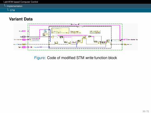
Variant Data
Figure: Code of modified STM write function block
Figure: Code of modified STM read function block
35 / 72

LabVIEW based Computer Control
Implementation
STM
Variant Data
Figure: Code of modified STM write function block
Figure: Code of modified STM read function block36 / 72

LabVIEW based Computer Control
Implementation
STM
Variant Data
Figure: Modified STM function blocks for writing and reading
37 / 72

LabVIEW based Computer Control
Implementation
STM
Command-Based Communication Framework
Client/Main Appl. Server/Driver
DataReceiver
Command/Parameter
Sender
Network Communication
Commands + Parameters
Data + Status Information
CommandParser
MediumPriorityTasks
High
Priority
Task
Figure: STM’s command-based communication framework
38 / 72

LabVIEW based Computer Control
Implementation
Main Program and Driver Structure
STM
Main Program
Medium Priority(Transmitter)
Command Parser
Medium Priority(Processor)
High Priority
Event Handler
Transmitter
Receiver
Main
Driver
STM
STM
Dat
aQ
ueu
e
Me
diu
m P
riori
t yQ
ueu
e
Hig
h P
riorit
yQ
ueu
e
STM
STM
Ma
in Q
ueu
e
Figure: Parallel loop structure of main program and drivers
39 / 72

LabVIEW based Computer Control
Implementation
Main Program and Driver Structure
Figure: Actual loop structure of driver
40 / 72

LabVIEW based Computer Control
Implementation
Resulting Information Flow
STM CommandGUI in
Main Appl.Driver Instrument
Instrument Bus
● Event structure● Queue● Main loop● Transmitter loop
● Command Parser● Queue● Medium Priority (Processor) loop● LabVIEW driver function block
STM
Bus CommandSTM Parameter
Figure: Resulting information flow on instrument control change
41 / 72

LabVIEW based Computer Control
Implementation
Usages
Goal: Relation between drivers and instruments
Figure: Instrument control clusters on instrument panel
42 / 72

LabVIEW based Computer Control
Implementation
Usages
Goal: Relation between drivers and instruments
Figure: Instrument control clusters on instrument panel
43 / 72

LabVIEW based Computer Control
Implementation
Usages
usage instrument 1
selects uses
driver 1
instrument 2 driver 2
instrument 3 driver 2
or
or
Figure: Usage concept
44 / 72

LabVIEW based Computer Control
Implementation
Usages
L-Band.CW sim.ini
; assignment of instrument to usage; ---------------------------------; usage = instrument name[config]stepper motor = "DS345(1)"signal = "DS345(2)"adc = "NI PCI-6024E"
45 / 72
LabVIEW based Computer Control
Implementation
Usages
L-Band.CW sim.ini
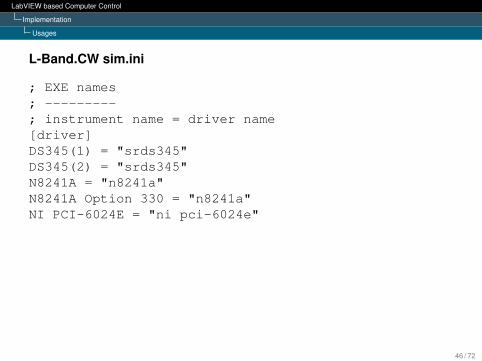
; EXE names; ---------; instrument name = driver name[driver]DS345(1) = "srds345"DS345(2) = "srds345"N8241A = "n8241a"N8241A Option 330 = "n8241a"NI PCI-6024E = "ni pci-6024e"
46 / 72
LabVIEW based Computer Control
Implementation
Usages
L-Band.CW sim.ini
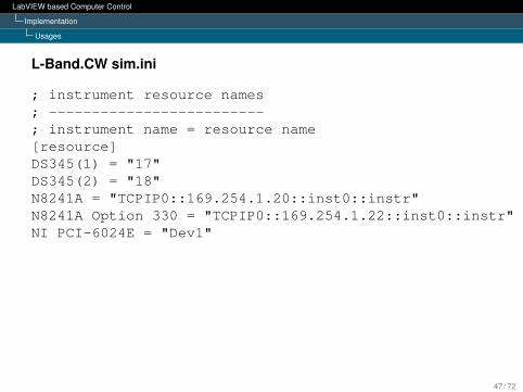
; instrument resource names; -------------------------; instrument name = resource name[resource]DS345(1) = "17"DS345(2) = "18"N8241A = "TCPIP0::169.254.1.20::inst0::instr"N8241A Option 330 = "TCPIP0::169.254.1.22::inst0::instr"NI PCI-6024E = "Dev1"
47 / 72
LabVIEW based Computer Control
Implementation
Usages
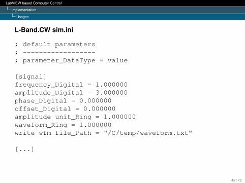
L-Band.CW sim.ini
; default parameters; ------------------; parameter_DataType = value
[signal]frequency_Digital = 1.000000amplitude_Digital = 3.000000phase_Digital = 0.000000offset_Digital = 0.000000amplitude unit_Ring = 1.000000waveform_Ring = 1.000000write wfm file_Path = "/C/temp/waveform.txt"
[...]
48 / 72

LabVIEW based Computer Control
Implementation
Usages
usage instrument 1
selects uses
driver 1
instrument 2 driver 2
instrument 3 driver 2
or
or
Figure: Usage concept
signal DS345
selects uses
sdrs345
N8241A n8241a
N8241A, 330 n8241a
or
or
Figure: Usage implementation
49 / 72

LabVIEW based Computer Control
Implementation
Hardware Abstraction
Goal: Select different instruments for a usage
Main Appl. Driver Instrument
standardizedSTM commands
instrumentspecific
bus commands
Figure: Driver as hardware abstraction layer
50 / 72

LabVIEW based Computer Control
Implementation
Hardware Abstraction
Figure: Driver’s command parser loop
51 / 72

LabVIEW based Computer Control
Implementation
Hardware Abstraction
Figure: Driver’s high priority loop
52 / 72
LabVIEW based Computer Control
Implementation
Implemented Experiment
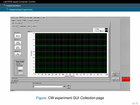
Figure: CW experiment GUI Collection page53 / 72

LabVIEW based Computer Control
Implementation
Implemented Experiment
Figure: CW experiment GUI Parameters page54 / 72
LabVIEW based Computer Control
Implementation
Implemented Experiment
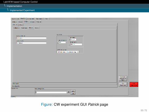
Figure: CW experiment GUI Patrick page55 / 72
LabVIEW based Computer Control
Implementation
Implemented Experiment
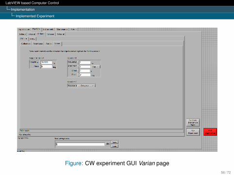
Figure: CW experiment GUI Varian page56 / 72

LabVIEW based Computer Control
Implementation
Implemented Experiment
Figure: CW experiment GUI Instrument panel57 / 72
Contents
1 Introduction
2 Concept
3 Implementation
4 Test
5 Summary and Vision

LabVIEW based Computer Control
Test
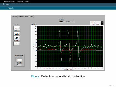
Measurement Setup
Measurement Setup
Sample : Spin labelMicrowave frequency : 1.908 GHz (L-Band)Microwave input power : 120 µWCenter field : 675 GSweep : 105 G, i.e. 622.5 G .. 727.5 GNumber of averages : 5Acquisition time : ≈ 5:30 min
59 / 72

LabVIEW based Computer Control
Test
Results
Figure: Collection page after 2nd collection
60 / 72

LabVIEW based Computer Control
Test
Results
Figure: Collection page after 3rd collection
61 / 72
LabVIEW based Computer Control
Test
Results
Figure: Collection page after 4th collection
62 / 72

LabVIEW based Computer Control
Test
Results
Figure: Collection page after 5th collection
63 / 72
LabVIEW based Computer Control
Test
Results
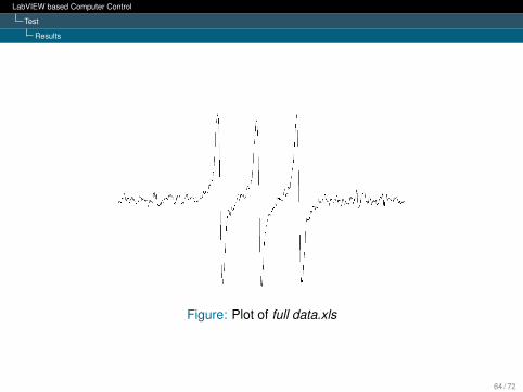
Figure: Plot of full data.xls
64 / 72

Contents
1 Introduction
2 Concept
3 Implementation
4 Test
5 Summary and Vision
LabVIEW based Computer Control
Summary and Vision
Key FeaturesI Can run on all spectrometers
I Can implement all experiments
I Faster experiment implementation
I Improved modularity and flexibility
I 32 and 64-bit driver capability
I Multi-core processors and multi-threading capable
66 / 72
LabVIEW based Computer Control
Summary and Vision
Key FeaturesI Can run on all spectrometers
I Can implement all experiments
I Faster experiment implementation
I Improved modularity and flexibility
I 32 and 64-bit driver capability
I Multi-core processors and multi-threading capable
67 / 72
LabVIEW based Computer Control
Summary and Vision
IssuesI Improve thread allocation
I Decrease time it takes to display acquired data
I Emphasize the common basis of experiments
68 / 72
LabVIEW based Computer Control
Summary and Vision
DiscoveriesI Shared variables work unreliable for some applications
I Module based concept for large projects
I STM with case structure to avoid polling for new messages
69 / 72
LabVIEW based Computer Control
Summary and Vision
Future ImprovementsI Adaptive Signal Averaging Technique
I Technical Data Management Streaming (TDMS)
I Implement more drivers
70 / 72

Any Questions?

Many thanks for your attention!