Embed Size (px)
Citation preview
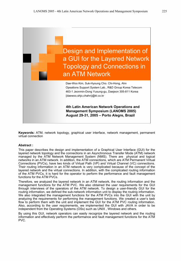
4th Latin American Network Operations and
Management Symposium (LANOMS 2005)
August 29-31, 2005 – Porto Alegre, Brazil
Design and Implementation of
a GUI for the Layered Network
Topology and Connections in
an ATM Network
Dae-Woo Kim, Suk-Hyoung Cho. Chi-Hong, Ahn
Opeations Support System Lab., R&D Group Korea Telecom
463-1 Jeonmin-Dong Yusung-gu, Daejeon 305-811 Korea
{daewoo,shjo,chahn}@kt.co.kr
Keywords: ATM, network topology, graphical user interface, network management, permanent virtual connection
Abstract :
This paper describes the design and implementation of a Graphical User Interface (GUI) for the layered network topology and the connections in an Asynchronous Transfer Mode (ATM) network managed by the ATM Network Management System (NMS). There are physical and logical networks in an ATM network. In addition, the ATM connections, which are ATM Permanent Virtual Connections (PVCs), have two kinds of Virtual Path (VP) and Virtual Channel (VC) connections. Their routing information in an ATM network is very complicated because of the concept of the layered network and the virtual connections. In addition, with the complicated routing information of the ATM PVCs, it is hard for the operator to perform the performance and fault management functions for the ATM PVCs.
Therefore, we analyzed the layered network in an ATM network, the routing information and the management functions for the ATM PVC. We also obtained the user requirements for the GUI through interviews of the operators of the ATM network. To design a user-friendly GUI for the routing information, we defined the sub-network information unit to display the routing information. We also integrated the management functions for the ATM PVCs into the GUI with the unit by analyzing the requirements for performing the management functions. We created a user’s task flow to perform them with the unit and implement the GUI for the ATM PVC routing information. Also, according to the user requirements, we implemented the GUI with JAVA in order to be independent from the Operating Systems (OSs) such as UNIX , Windows and others.
By using this GUI, network operators can easily recognize the layered network and the routing information and effectively perform the performance and fault management functions for the ATM PVC.
LANOMS 2005 - 4th Latin American Network Operations and Management Symposium 225
4th Latin American Network Operations and Management Symposium (LANOMS 2005)
Introduction
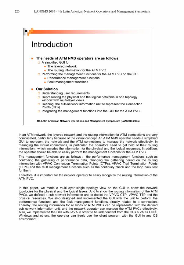
The needs of ATM NMS operators are as follows:A simplified GUI for
The layered network
The routing information for the ATM PVC
Performing the management functions for the ATM PVC on the GUI
Performance management functions
Fault management functions
Our SolutionUnderstanding user requirements
Representing the physical and the logical networks in one topology window with multi-layer views
Defining the sub-network information unit to represent the Connection Points (CPs)
Integrating the management functions into the GUI for the ATM PVC
In an ATM network, the layered network and the routing information for ATM connections are very complicated, particularly because of the virtual concept. An ATM NMS operator needs a simplified GUI to represent the network and the ATM connections to manage the network effectively. In managing the virtual connections, in particular, the operators need to get hold of their routing information, which includes the information for the physical and the logical resources. In addition, the operator should be able to easily perform the management functions for the ATM PVC.
The management functions are as follows : the performance management functions such as controlling the gathering of performance data, changing the gathering period on the routing information with VP/VC Connection Termination Points (CTPs), VP/VC Trail Termination Points (TTPs) and the fault management functions such as the continuity check and the loop back test for them.
Therefore, it is important for the network operator to easily recognize the routing information of the ATM PVC.
In this paper, we made a multi-layer single-topology view on the GUI to show the network topologies for the physical and the logical layers. And to show the routing information of the ATM PVCs, we defined a sub-network information unit to depict the VP/VC CTP, VP/VC TTP and the physical resources. We also designed and implemented the GUI with the unit to perform the performance functions and the fault management functions directly related to a connection. Thereby, the routing information for all kinds of ATM PVCs can be represented with the defined sub-network information unit, and the network operator can manage the ATM PVCs effectively. Also, we implemented the GUI with JAVA in order to be independent from the OSs such as UNIX, Windows and others. the operator can freely use the client program with the GUI in any OS environment.
226 LANOMS 2005 - 4th Latin American Network Operations and Management Symposium
4th Latin American Network Operations and Management Symposium (LANOMS 2005)
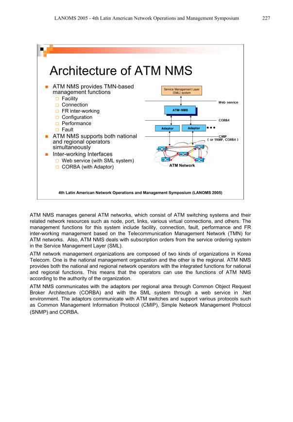
Architecture of ATM NMSATM NMS provides TMN-based management functions
Facility
Connection
FR inter-working
Configuration
Performance
Fault
ATM NMS supports both national and regional operators simultaneously
Inter-working InterfacesWeb service (with SML system)
CORBA (with Adaptor) ATM Network
ATM NMS manages general ATM networks, which consist of ATM switching systems and their
related network resources such as node, port, links, various virtual connections, and others. The
management functions for this system include facility, connection, fault, performance and FR
inter-working management based on the Telecommunication Management Network (TMN) for
ATM networks. Also, ATM NMS deals with subscription orders from the service ordering system
in the Service Management Layer (SML).
ATM network management organizations are composed of two kinds of organizations in Korea
Telecom. One is the national management organization and the other is the regional. ATM NMS
provides both the national and regional network operators with the integrated functions for national
and regional functions. This means that the operators can use the functions of ATM NMS
according to the authority of the organization.
ATM NMS communicates with the adaptors per regional area through Common Object Request
Broker Architecture (CORBA) and with the SML system through a web service in .Net
environment. The adaptors communicate with ATM switches and support various protocols such
as Common Management Information Protocol (CMIP), Simple Network Management Protocol
(SNMP) and CORBA.
LANOMS 2005 - 4th Latin American Network Operations and Management Symposium 227
4th Latin American Network Operations and Management Symposium (LANOMS 2005)
Layer Networks in an ATM
Network
The relationship between VP and VC layer network VC link with one termination point
VCnode
VCnode
VCnode
VPnode
Physical Network
VP Layer Network
VC Layer Network
VPXC/SW
VP/VCSW
VP/VCSW
VP/VCSW
VPnode
VPnode
VPnode
CPECPE
: port in a network: Link in a network
: trail in VP layer network : trail termination point in a VP layer networknetwork
user-to-network
trail
network-to-network
trail
VCnode
VCnode
VCnode
VPnode
Physical Network
VP Layer Network
VC Layer Network
VPXC/SW
VP/VCSW
VP/VCSW
VP/VCSW
VPnode
VPnode
VPnode
CPECPE
VPnode
VPnode
VPnode
CPECPE
: port in a network: Link in a network
: trail in VP layer network : trail termination point in a VP layer networknetwork
: port in a network: Link in a network
: trail in VP layer network : trail termination point in a VP layer networknetwork
user-to-network
trail
network-to-network
trail
Physical Network
ATM SWITCHATM SWITCH
VP Layer Network and VC Layer Network
CPE
VC CTP + inteworking VC TTP + frsDLCCTP (FR interworking Port)
VC CTP
VP CTP + VP TTP + VC LinkTP VP CTP
VC TTP FR port
Physical Network
ATM SWITCHATM SWITCHATM SWITCHATM SWITCH
VP Layer Network and VC Layer Network
CPE
VC CTP + inteworking VC TTP + frsDLCCTP (FR interworking Port)
VC CTP
VP CTP + VP TTP + VC LinkTP VP CTP
VC TTP FR port
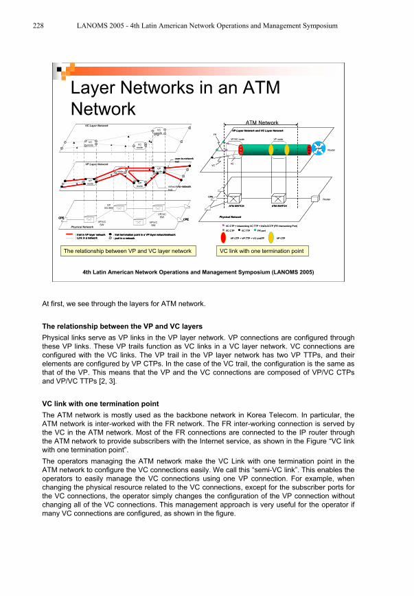
At first, we see through the layers for ATM network.
The relationship between the VP and VC layers
Physical links serve as VP links in the VP layer network. VP connections are configured through
these VP links. These VP trails function as VC links in a VC layer network. VC connections are
configured with the VC links. The VP trail in the VP layer network has two VP TTPs, and their
elements are configured by VP CTPs. In the case of the VC trail, the configuration is the same as
that of the VP. This means that the VP and the VC connections are composed of VP/VC CTPs
and VP/VC TTPs [2, 3].
VC link with one termination point
The ATM network is mostly used as the backbone network in Korea Telecom. In particular, the
ATM network is inter-worked with the FR network. The FR inter-working connection is served by
the VC in the ATM network. Most of the FR connections are connected to the IP router through
the ATM network to provide subscribers with the Internet service, as shown in the Figure “VC link
with one termination point”.
The operators managing the ATM network make the VC Link with one termination point in the
ATM network to configure the VC connections easily. We call this “semi-VC link”. This enables the
operators to easily manage the VC connections using one VP connection. For example, when
changing the physical resource related to the VC connections, except for the subscriber ports for
the VC connections, the operator simply changes the configuration of the VP connection without
changing all of the VC connections. This management approach is very useful for the operator if
many VC connections are configured, as shown in the figure.
228 LANOMS 2005 - 4th Latin American Network Operations and Management Symposium
4th Latin American Network Operations and Management Symposium (LANOMS 2005)
Management Functions Related to
ATM PVC
Performance
management
functions
Fault
management
functions
NE MOs for ATM PVC and the management functions
vcTTPBidirectional
managedElementR1
tcAdaptor TTPBidirectional
vpCTPBidirectional
vcCTPBidirectional
bidirectionalContinuityMonitor
upcNpcCurrentData
atmTrafficLoadCurrentData
upcNpcHistoryData
atmTrafficLoadHistorytData
bidirectionalPerformance
Monitor
vpVcPMCurrentData
vpVcPMHistoryData
vpTTPBidirectional
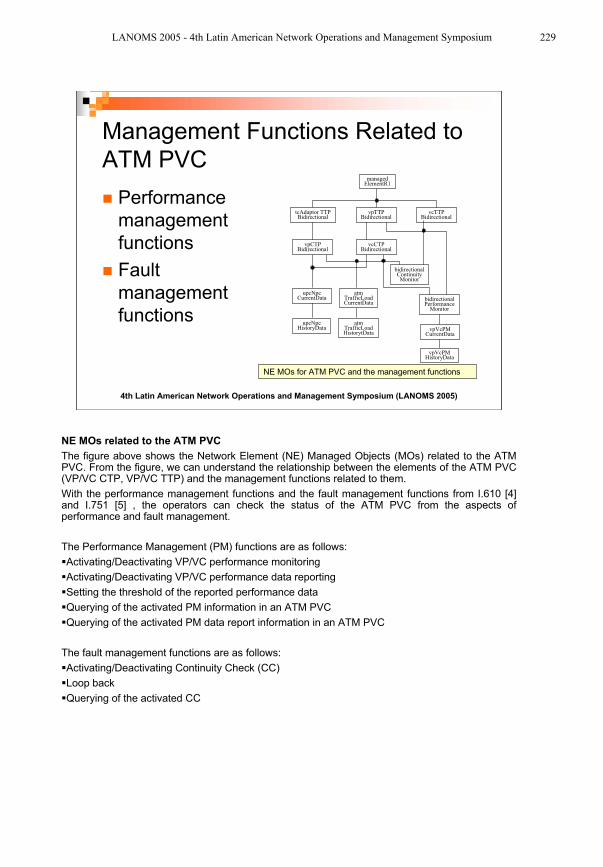
NE MOs related to the ATM PVC
The figure above shows the Network Element (NE) Managed Objects (MOs) related to the ATM PVC. From the figure, we can understand the relationship between the elements of the ATM PVC (VP/VC CTP, VP/VC TTP) and the management functions related to them.
With the performance management functions and the fault management functions from I.610 [4] and I.751 [5] , the operators can check the status of the ATM PVC from the aspects of performance and fault management.
The Performance Management (PM) functions are as follows:
Activating/Deactivating VP/VC performance monitoring
Activating/Deactivating VP/VC performance data reporting
Setting the threshold of the reported performance data
Querying of the activated PM information in an ATM PVC
Querying of the activated PM data report information in an ATM PVC
The fault management functions are as follows:
Activating/Deactivating Continuity Check (CC)
Loop back
Querying of the activated CC
LANOMS 2005 - 4th Latin American Network Operations and Management Symposium 229
4th Latin American Network Operations and Management Symposium (LANOMS 2005)
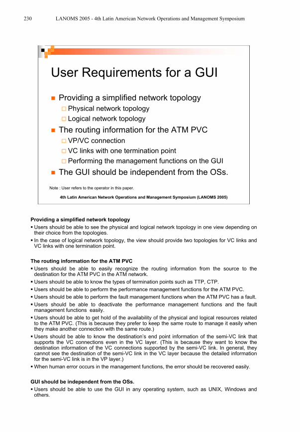
User Requirements for a GUI
Providing a simplified network topology
Physical network topology
Logical network topology
The routing information for the ATM PVC
VP/VC connection
VC links with one termination point
Performing the management functions on the GUI
The GUI should be independent from the OSs.
Note : User refers to the operator in this paper.
Providing a simplified network topology
Users should be able to see the physical and logical network topology in one view depending on their choice from the topologies.
In the case of logical network topology, the view should provide two topologies for VC links and VC links with one termination point.
The routing information for the ATM PVC
Users should be able to easily recognize the routing information from the source to the destination for the ATM PVC in the ATM network.
Users should be able to know the types of termination points such as TTP, CTP.
Users should be able to perform the performance management functions for the ATM PVC.
Users should be able to perform the fault management functions when the ATM PVC has a fault.
Users should be able to deactivate the performance management functions and the fault management functions easily.
Users should be able to get hold of the availability of the physical and logical resources related to the ATM PVC. (This is because they prefer to keep the same route to manage it easily when they make another connection with the same route.)
Users should be able to know the destination’s end point information of the semi-VC link that supports the VC connections even in the VC layer. (This is because they want to know the destination information of the VC connections supported by the semi-VC link. In general, they cannot see the destination of the semi-VC link in the VC layer because the detailed information for the semi-VC link is in the VP layer.)
When human error occurs in the management functions, the error should be recovered easily.
GUI should be independent from the OSs.
Users should be able to use the GUI in any operating system, such as UNIX, Windows and others.
230 LANOMS 2005 - 4th Latin American Network Operations and Management Symposium
4th Latin American Network Operations and Management Symposium (LANOMS 2005)
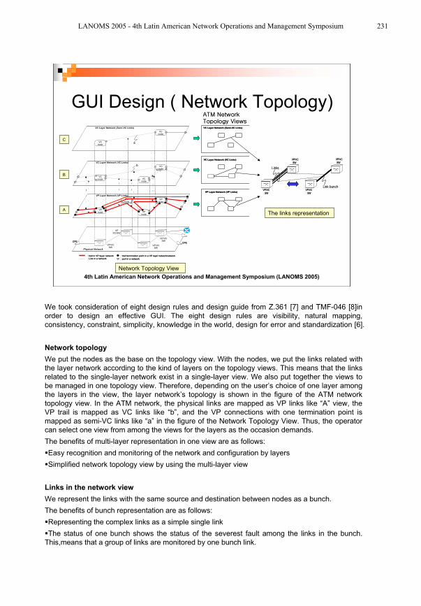
GUI Design ( Network Topology)
A
B
C
Network Topology View
The links representation
VCnode
VCnode
VCnode
VPnode
Physical Network
VP Layer Network (VP Links)
VC Layer Network (VC Links)
VPXC/SW
VP/VCSW
VP/VCSW
VP/VCSW
VPnode
VPnode
VPnode
CPECPE
: port in a network: Link in a network
: trail in VP layer network : trail termination point in a VP layer networknetwork
VCnode
VCnode
VC Layer Network (Semi-VC Links)
VC Layer Network (VC Links)
VC Layer Network (Semi-VC Links)
VP Layer Network (VP Links)
VCnode
VCnode
VCnode
VPnode
Physical Network
VP Layer Network (VP Links)
VC Layer Network (VC Links)
VPXC/SW
VP/VCSW
VP/VCSW
VP/VCSW
VPnode
VPnode
VPnode
CPECPE
: port in a network: Link in a network
: trail in VP layer network : trail termination point in a VP layer networknetwork
VCnode
VCnode
VC Layer Network (Semi-VC Links)
VC Layer Network (VC Links)
VC Layer Network (Semi-VC Links)
VP Layer Network (VP Links)
VP/VC
SW
VP/VC
SW
VP/VC
SW
VP/VC
SW
VP/VC
SW
VP/VC
SW
VP/VC
SW
VP/VC
SW
We took consideration of eight design rules and design guide from Z.361 [7] and TMF-046 [8]in
order to design an effective GUI. The eight design rules are visibility, natural mapping,
consistency, constraint, simplicity, knowledge in the world, design for error and standardization [6].
Network topology
We put the nodes as the base on the topology view. With the nodes, we put the links related with
the layer network according to the kind of layers on the topology views. This means that the links
related to the single-layer network exist in a single-layer view. We also put together the views to
be managed in one topology view. Therefore, depending on the user’s choice of one layer among
the layers in the view, the layer network’s topology is shown in the figure of the ATM network
topology view. In the ATM network, the physical links are mapped as VP links like “A” view, the
VP trail is mapped as VC links like “b”, and the VP connections with one termination point is
mapped as semi-VC links like “a” in the figure of the Network Topology View. Thus, the operator
can select one view from among the views for the layers as the occasion demands.
The benefits of multi-layer representation in one view are as follows:
Easy recognition and monitoring of the network and configuration by layers
Simplified network topology view by using the multi-layer view
Links in the network view
We represent the links with the same source and destination between nodes as a bunch.
The benefits of bunch representation are as follows:
Representing the complex links as a simple single link
The status of one bunch shows the status of the severest fault among the links in the bunch.
This,means that a group of links are monitored by one bunch link.
LANOMS 2005 - 4th Latin American Network Operations and Management Symposium 231
4th Latin American Network Operations and Management Symposium (LANOMS 2005)
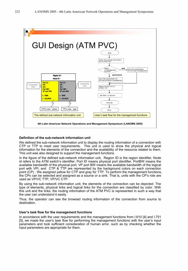
GUI Design (ATM PVC)
The defined sub-network information unit User’s task flow for the management functions
’ ’’ ’
Definition of the sub-network information unit
We defined the sub-network information unit to display the routing information of a connection with CTP or TTP to meet user requirements. This unit is used to show the physical and logical information for the elements of the connection and the availability of the resource related to them. This unit was also designed to support the management functions.
In the figure of the defined sub-network information unit, Region ID is the region identifier, Node id refers to the ATM switch’s identifier, Port ID means physical port identifier, PortBW means the available bandwidth of the physical port, VP port BW means the available bandwidth of the logical port with VPI, and CTP & TTP are represented by the background colors on each connection point (CP) . We assigned yellow for CTP and gray for TTP. To perform the management functions, the CPs can be selected and assigned as a source or a sink. That is, units with the CP’s role are used as VP/VC TTP, VP/VC CTP.
By using the sub-network information unit, the elements of the connection can be depicted. The type of elements, physical links and logical links for the connection are classified by color. With this unit and the links, the routing information of the ATM PVC is represented in such a way that the user can understand it easily.
Thus, the operator can see the browsed routing information of the connection from source to destination.
User’s task flow for the management functions
In accordance with the user requirements and the management functions from I.610 [4] and I.751 [5], we made the user's task flow for performing the management functions with the user’s input parameters and took sufficient consideration of human error, such as by checking whether the input parameters are appropriate for them.
232 LANOMS 2005 - 4th Latin American Network Operations and Management Symposium
4th Latin American Network Operations and Management Symposium (LANOMS 2005)
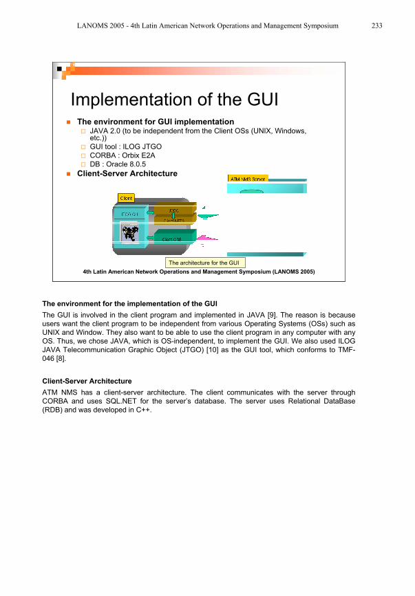
Implementation of the GUIThe environment for GUI implementation
JAVA 2.0 (to be independent from the Client OSs (UNIX, Windows, etc.))
GUI tool : ILOG JTGO
CORBA : Orbix E2A
DB : Oracle 8.0.5
Client-Server Architecture
The architecture for the GUI
The environment for the implementation of the GUI
The GUI is involved in the client program and implemented in JAVA [9]. The reason is because
users want the client program to be independent from various Operating Systems (OSs) such as
UNIX and Window. They also want to be able to use the client program in any computer with any
OS. Thus, we chose JAVA, which is OS-independent, to implement the GUI. We also used ILOG
JAVA Telecommunication Graphic Object (JTGO) [10] as the GUI tool, which conforms to TMF-
046 [8].
Client-Server Architecture
ATM NMS has a client-server architecture. The client communicates with the server through
CORBA and uses SQL.NET for the server’s database. The server uses Relational DataBase
(RDB) and was developed in C++.
LANOMS 2005 - 4th Latin American Network Operations and Management Symposium 233
4th Latin American Network Operations and Management Symposium (LANOMS 2005)
Implemented GUI (Network Topology)
The buttons for selection of layer
LinksLink bunch
Network Topology View Link bunch & Links
Network Topology View
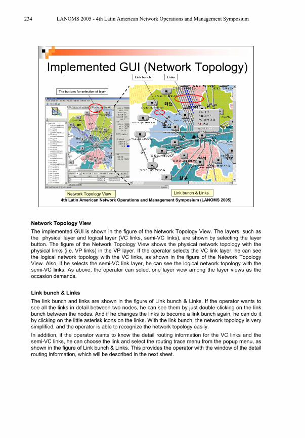
The implemented GUI is shown in the figure of the Network Topology View. The layers, such as
the physical layer and logical layer (VC links, semi-VC links), are shown by selecting the layer
button. The figure of the Network Topology View shows the physical network topology with the
physical links (i.e. VP links) in the VP layer. If the operator selects the VC link layer, he can see
the logical network topology with the VC links, as shown in the figure of the Network Topology
View. Also, if he selects the semi-VC link layer, he can see the logical network topology with the
semi-VC links. As above, the operator can select one layer view among the layer views as the
occasion demands.
Link bunch & Links
The link bunch and links are shown in the figure of Link bunch & Links. If the operator wants to
see all the links in detail between two nodes, he can see them by just double-clicking on the link
bunch between the nodes. And if he changes the links to become a link bunch again, he can do it
by clicking on the little asterisk icons on the links. With the link bunch, the network topology is very
simplified, and the operator is able to recognize the network topology easily.
In addition, if the operator wants to know the detail routing information for the VC links and the
semi-VC links, he can choose the link and select the routing trace menu from the popup menu, as
shown in the figure of Link bunch & Links. This provides the operator with the window of the detail
routing information, which will be described in the next sheet.
234 LANOMS 2005 - 4th Latin American Network Operations and Management Symposium
4th Latin American Network Operations and Management Symposium (LANOMS 2005)
Implemented GUI (ATM PVC)
The routing information window for VC link The routing information window for semi-VC link
The routing information
window for VC connection
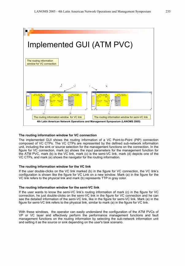
The routing information window for VC connection
The implemented GUI shows the routing information of a VC Point-to-Point (PtP) connection composed of VC CTPs. The VC CTPs are represented by the defined sub-network information unit, including the sink or source selection for the management functions on the connection. In the figure for VC connection, mark (a) shows the input parameters for the management function for the ATM PVC, mark (b) is the VC link, mark (c) is the semi-VC link, mark (d) depicts one of the VC CTPs, and mark (e) shows the navigator for the routing information.
The routing information window for the VC link
If the user double-clicks on the VC link marked (b) in the figure for VC connection, the VC link’s configuration is shown like the figure for VC Link on a new window. Mark (a) in the figure for the VC link refers to the physical link and mark (b) represents TTP in gray color.
The routing information window for the semi-VC link
If the user wants to know the semi-VC link’s routing information of mark (c) in the figure for VC connection, he just double-clicks on the semi-VC link in the figure for VC connection and he can see the detailed information of the semi-VC link, like in the figure for semi-VC link. Mark (a) in the figure for semi-VC link refers to the physical link, similar to mark (a) in the figure for VC link.
With these windows, the operator can easily understand the configuration of the ATM PVCs of VP or VC layer and effectively perform the performance management functions and fault management functions on the routing information by selecting the sub-network information unit and setting it as the source or sink depending on the user's task scenario.
LANOMS 2005 - 4th Latin American Network Operations and Management Symposium 235
4th Latin American Network Operations and Management Symposium (LANOMS 2005)
Conclusion
Providing an effective GUI for ATM Network operators Reducing the complication of the ATM Network Topology by using multi-layer for the layers
Simplifying the network topology by using the link bunch
Providing a GUI for the routing information for the ATM PVC to the operator
Enabling the operator to easily recognize the routing information and effectively manage the ATM PVC with the defined sub-network information unit
Performing the performance and fault management functions for the ATM PVC on the GUI in an easy manner
Future studyTo show the fault status of the CPs of the routing information
In this paper, we analyzed the ATM network topology and used the multi-layer to show the network topologies for various layers, and we used the link bunch to show the links simply on the GUI. In addition, after we have sufficiently analyzed the routing information for the ATM PVCs and their management functions, we defined the sub-network information unit and made the GUI of the routing information for ATM connections using this, which supports the management functions on the GUI.
Therefore, the ATM network operator can recognize the physical and logical network topology and easily grasp the configuration of the ATM PVCs and effectively perform the management functions related to the ATM PVCs. However, further research studies to show the fault status of the CPs and the links on the GUI of the routing information are required.
REFERENCES
[1] Telecommunication Network Laboratory, Korea Telecom , Requirements for ATM Network Management System , February 1, 2002
[2] Telecommunication Network Laboratory, Korea Telecom, Behavior of Network Element to connect with ATM subNMS for Super Information Highway in Korea, September 12, 1998
[3] af-nm-0073-000, M4 Network View CMIP MIB Specification Version 1.0, The ATM Forum, January 1997
[4] ITU-T Rec. I.610, B-ISDN OPERATION AND MAINTENANCE PRINCIPLES AND FUNCTIONS, COM 13-27-E, January 1998
[5] ITU-T Rec. I.751, ASYNCHRONOUS TRANSFER MODE MANAGEMENT OF THE NETWORK ELEMENT VIEW, March 1996
[6] Douglas Talbott, Coming to Our Senses : Multi-Modal User Interfaces, Design Management Journal, 1997
[7] ITU-T Rec. Z361, Design guidelines for Human-Computer Interface (HCI) for the management of telecommunications networks, February 1999
[8] TMF-046 (Graphic Information Requirements for Telecommunications Management Objects), Version2.1, September 1999
[9] Kathy Walrath & Mary Campione, The JFC Swing Tutorial A Guide to Constructing GUIs, Sun Microsystems,2000
[10] ILOG JTGO : http://www ilog com/products/jtgo/
236 LANOMS 2005 - 4th Latin American Network Operations and Management Symposium