Embed Size (px)
Citation preview
Arab Journal of Nuclear Science and Applications, 94 (2), (85-98) 2016
58
Design and Implementation of a Fuzzy Logic Controller for the Pressurized
Water Power Reactor Control
S.A. Kotb1 M.M. Metwally2, and K.M. Rady2
1 ETRR2, Atomic Energy Authority, Cairo , Egypt 2Faculty of Engineering, Cairo University, Cairo, Egypt
Received: 25/5/2015 Accepted: 1/9/2015
ABSTRACT The pressurized water reactor type power plant has a sophisticated automatic
control systems. On the primary side, The Control rod system and the Soluble boron
control the core neutron flux. On the secondary side, output steam is controlled by
the turbine control valve and steam dump system. During the automatic control
mode, the two sides work in a synchronized way so that transition to stabilized
conditions will be achieved smoothly. This paper presents a detailed nuclear power
model for the medium-term and long-term power system stability. This model can be used to analyze the difference transient fault on electrical grid. Also this work
introduces the effect of utilizing the Fuzzy logic control methodology in the power
control model of the PWR (pressurized water reactor). The fuzzy logic controller
was tested on a PWR model using the Matlab Simulink Interface. Two case studies
were performed on the model using both the fuzzy logic method and the traditional
rod speed program for controlling the nuclear power plant variables. The
proposed controller presented a higher performance than that of the traditional rod speed program controller.
Key Words: Power system; Fuzzy Logic, Nuclear Power Plant Model
INTRODUCTION
The power and temperature of a nuclear reactor should be properly controlled in order to maintain the performance of the reactor’s operating conditions as well as to maximize the thermal efficiency of an entire nuclear power plant. However, power plants are highly complex, nonlinear, time-varying, and constrained systems. If a load-following operation is desired, the daily load cycles can change plant performance significantly. Advanced power tracking control of nuclear reactors has not been accepted mainly due to the safety concerns stemming from imprecise knowledge about the time-varying parameters, nonlinearity, and modeling uncertainty. However, rapid and smooth power maneuvering has its benefits in view of the economical and safe operation of reactors and the importance of a load-following strategy (1-4). Modern nuclear power plants should respond to the load demand on the power grid, which demand high plant operation performance, subject to various kinds of constraints. Meanwhile, nuclear safety and radioactive pollution prevention have long been much concerned problems. One of the early works on power control in nuclear reactors presented a water level controller in a PWR steam generator (5). In 1998, a nuclear power reactor fuzzy controller simulator using Matlab was developed (6). An analysis of the safety aspects of fuzzy controller implementation in nuclear reactors was reported in 2000 (7,8). Also in this work, the results of a comparison study between a classical rod speed program and a fuzzy logic controller applied to nuclear reactors were presented (9). Subsequent work has been done evaluating the strengths and weaknesses of fuzzy controllers applied to nuclear reactors (10). Most of the work on power control of nuclear reactors using fuzzy logic shows, through computer simulations, the feasibility of its implementation (11,12). In this paper, a detailed nuclear power plant model is proposed. In this model, the steam turbine model is simplified, while the coolant pump model. Fuzzy logic and conventional rod speed program for the reactor power control system are included. Then a user-defined program of Matlab Simulink Interface modeling the nuclear power plant is implemented. The program can revise
Arab Journal of Nuclear Science and Applications, 94 (2), (85-98) 2016
58
and debug very easily, for the user only need to modify the Matlab transfer function diagram of certain modules if needed. Based on this program, the response of nuclear power plant to the disturbance of power grid is simulated.
Modeling the Nuclear Power Plant System
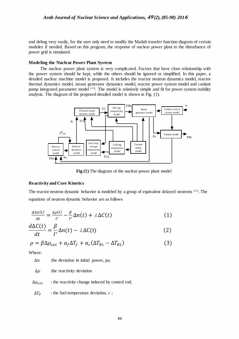
The nuclear power plant system is very complicated. Factors that have close relationship with the power system should be kept, while the others should be ignored or simplified. In this paper, a detailed nuclear machine model is proposed. It includes the reactor neutron dynamics model, reactor thermal dynamics model, steam generator dynamics model, reactor power system model and coolant pump integrated parameter model (13). The model is relatively simple and fit for power system stability analysis. The diagram of the proposed detailed model is shown in Fig. (1).
Neutron
dynamics
model
Frist loop
average
temperature
model
Cold leg
temperature
model
Coolant
pump
model
Thermal output
dynamic model
Reactor
control
model
Hot leg
temperature
model
Steam
generator model
Turbine control
system model
Turbine model
PM
PM Ps
TCTHL
Ps
w
N TCL
TCL
ext
Fig (1) The diagram of the nuclear power plant model
Reactivity and Core Kinetics
The reactor neutron dynamic behavior is modeled by a group of equivalent delayed neutrons (13). The
equations of neutron dynamic behavior are as follows
𝑑∆𝑛(𝑡)
𝑑𝑡=
∆𝜌(𝑡)
𝑙∗−
𝛽
𝑙∗∆𝑛(𝑡) + ∆𝐶(𝑡) (1)
𝑑∆𝐶(𝑡)
𝑑𝑡=𝛽
𝑙∗∆𝑛(𝑡) − ∆C(t) (2)
𝜌 = 𝛽∆𝜌𝑒𝑥𝑡 +𝛼𝑓∆𝑇𝑓 +𝛼𝑐(∆𝑇𝜃1 −∆𝑇𝜃2) (3)
Where:
∆𝑛 :the deviation in initial power, pu;
∆𝜌 :the reactivity deviation
∆𝜌𝑒𝑥𝑡 : the reactivity change induced by control rod;
∆𝑇𝐹 : the fuel temperature deviation, c ;
Arab Journal of Nuclear Science and Applications, 94 (2), (85-98) 2016
58
∆𝑇𝜃1 : the coolant node 1 temperature deviation, c ;
∆𝑇𝜃2 : the coolant node 2 temperature deviation, c ;
𝛽 : the delayed neutron group fraction;
the equivalent decay constant , 1/s;
𝛼𝑓 : the fuel coefficient of reactivity, 1/c ;
𝛼𝑐 : the coolant coefficient of reactivity, 1/c .
The Thermal Output Dynamics Model
The thermal output dynamic model can be expressed by the first order differential equations, as is shown.
)( 1
0
FC
PFFPFF
fTT
Cm
hAn
Cm
fP
dt
Td
(4)
)()()1(
1101
CCL
C
CCF
PcCPcC
C TTm
mTT
Cm
hAn
Cm
Pf
dt
Td
(5)
)()()1(
21102
CC
C
CCF
PcCPcC
C TTm
mTT
Cm
hAn
Cm
Pf
dt
Td
(6)
Where
0P :the initial power level, Mw
f :the fraction of the total power produced in the fuel
h :the heat transfer coefficient from fuel to coolant, w/m2.k
A :the heat transfer area, m2
Fm :the mass of fuel, kg
PFc :the specific heat of fuel, Kj/kg.k
Cm :the mass of coolant, kg
PCC :the specific heat of coolant, Kj/kg.k
Cm
:the mass flow rate in core, kg/s
Arab Journal of Nuclear Science and Applications, 94 (2), (85-98) 2016
55
The Hot Leg and Cold Leg Temperature Model
The hot leg and cold leg temperature model can be expressed by the first order differential equations,
as:
)(1
2 HLC
HL
HL TTdt
Td
(7)
)(1
CLoP
CL
CL TTdt
Td
(8)
Where:
HLT : the hot leg temperature deviation, C
CLT : the cold leg temperature deviation, C
OPT : the primary fluid lump temperature deviation, C
HL : the hot leg heat transfer time constant, s
CL : the cold leg heat transfer time constant, s
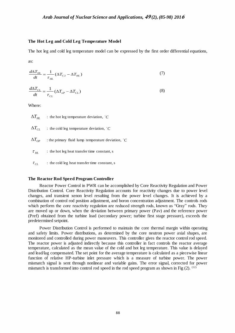
The Reactor Rod Speed Program Controller
Reactor Power Control in PWR can be accomplished by Core Reactivity Regulation and Power Distribution Control. Core Reactivity Regulation accounts for reactivity changes due to power level changes, and transient xenon level resulting from the power level changes. It is achieved by a combination of control rod position adjustment, and boron concentration adjustment. The controls rods which perform the core reactivity regulation are reduced strength rods, known as “Gray” rods. They are moved up or down, when the deviation between primary power (Pav) and the reference power (Pref) obtained from the turbine load (secondary power; turbine first stage pressure), exceeds the predetermined setpoint.
Power Distribution Control is performed to maintain the core thermal margin within operating and safety limits. Power distributions, as determined by the core neutron power axial shapes, are monitored and controlled during power maneuvers. This controller gives the reactor control rod speed. The reactor power is adjusted indirectly because this controller in fact controls the reactor average temperature, calculated as the mean value of the cold and hot leg temperature. This value is delayed and lead/lag compensated. The set point for the average temperature is calculated as a piecewise linear function of relative HP-turbine inlet pressure which is a measure of turbine power. The power mismatch signal is sent through nonlinear and variable gains. The error signal, corrected for power mismatch is transformed into control rod speed in the rod speed program as shown in Fig (2). (12)
Arab Journal of Nuclear Science and Applications, 94 (2), (85-98) 2016
58
Fig (2) Reactor rod speed program controller.
The time constant T as showing in table (1)
Table (1) time constant of T.
Constant Values sec
T1 40
T2 30
T3 8
T4 50
T5 10
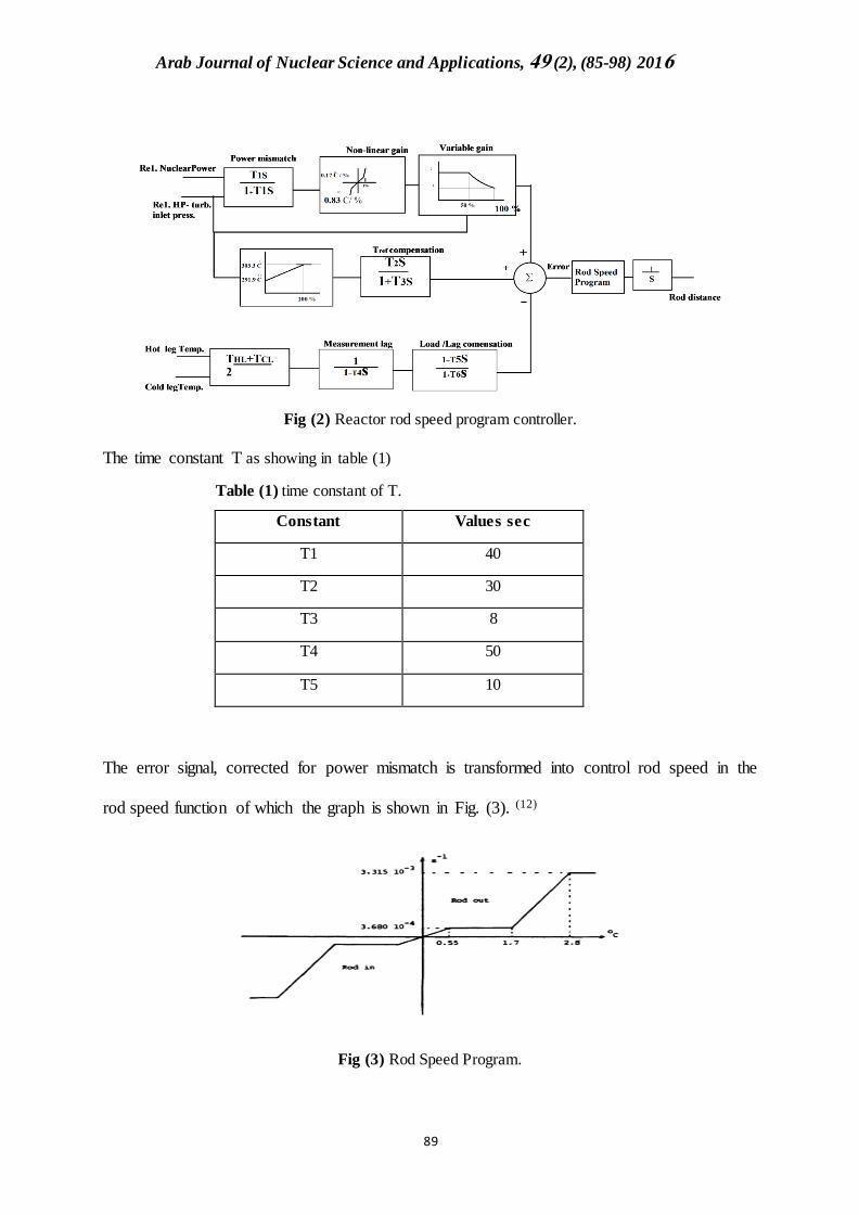
The error signal, corrected for power mismatch is transformed into control rod speed in the
rod speed function of which the graph is shown in Fig. (3). (12)
Fig (3) Rod Speed Program.
Arab Journal of Nuclear Science and Applications, 94 (2), (85-98) 2016
89
The following equation is described the traditional rod speed program with function of error.
𝑹 𝑺 =
{
= 3.3115𝑒(−3) ∗ 𝐸𝑟 , 𝐼𝑓 𝐸𝑟 ≤ −2.8
= − ((((3.315𝑒−3 − 3.68𝑒−4) ∗ Er − (3.68𝑒−4 ∗ 2.8 − 3.315𝑒−3 ∗ 1.7))/(2.8 − 1.7))
+3.68𝑒−4 ∗ Er If Er ≥ −2.8
=((−3.315𝑒−3 − 3.68𝑒−4) ∗ Er − 3.68𝑒−4 ∗ 2.8 − 3.315𝑒−3 ∗ 1.7 )
(2.8 − 1.7)+ (3.68𝑒−4Er)
(If Er ≥ −1.7)
= (3.68𝑒−4 +3.68𝑒−4
0.55) ∗ 𝐸𝑟 𝐼𝑓 (𝐸𝑟 > −0.55)
= (3.68𝑒−4 −3.68𝑒−4
0.55) ∗ 𝐸𝑟 𝐼𝑓 (𝐸𝑟 > 0.55)
=((−3.315𝑒−3− 3.68𝑒−4) ∗ Er + (3.68𝑒−4 ∗ 2.8 − 3.315𝑒−3 ∗ 1.7) )
(2.8 − 1.7)
−(3.68𝑒−4Er) (If Er ≥ 1.7)
= (((3.315𝑒−3 − 3.68𝑒−4) ∗ Er + (3.68𝑒−4 ∗ 2.8 − 3.315𝑒−3 ∗ 1.7))/(2.8 − 1.7))
−3.315𝑒−3) ∗ Er If Er ≥ 2.8
(9)
Where
RS: Rod speed
Er : Error
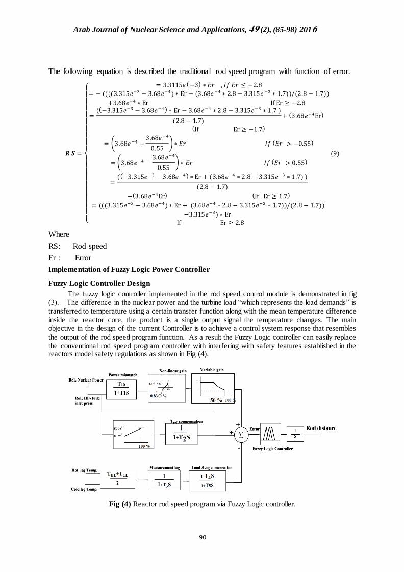
Implementation of Fuzzy Logic Power Controller
Fuzzy Logic Controller Design
The fuzzy logic controller implemented in the rod speed control module is demonstrated in fig (3). The difference in the nuclear power and the turbine load “which represents the load demands” is transferred to temperature using a certain transfer function along with the mean temperature difference inside the reactor core, the product is a single output signal the temperature changes. The main objective in the design of the current Controller is to achieve a control system response that resembles the output of the rod speed program function. As a result the Fuzzy Logic controller can easily replace the conventional rod speed program controller with interfering with safety features established in the reactors model safety regulations as shown in Fig (4).
Fig (4) Reactor rod speed program via Fuzzy Logic controller.
Arab Journal of Nuclear Science and Applications, 94 (2), (85-98) 2016
89
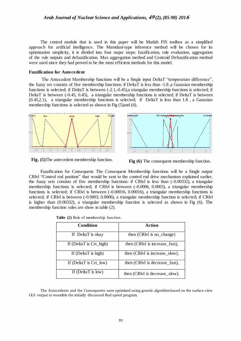
The control module that is used in this paper will be Matlab FIS toolbox as a simplified approach for artificial intelligence. The Mamdani-type inference method will be chosen for its optimization simplicity, it is divided into four major steps: fuzzification, rule evaluation, aggregation of the rule outputs and defuzzification. Max aggregation method and Centroid Defuzzification method were used since they had proved to be the most efficient methods for this model.
Fuzzification for Antecedent
The Antecedent Membership functions will be a Single input DeltaT “temperature difference”, the fuzzy set consists of five membership functions: if DeltaT is less than -1.8 ,a Gaussian membership functions is selected; if DeltaT is between (-2.1,-0.45),a triangular membership functions is selected; if DeltaT is between (-0.45, 0.45), a triangular membership functions is selected; if DeltaT is between (0.45,2.1), a triangular membership functions is selected; if DeltaT is less than 1.8 , a Gaussian membership functions is selected as shown in Fig (5)and (6).
Fig. (5)The antecedent membership function.
Fig (6) The consequent membership function.
Fuzzification for Consequent: The Consequent Membership functions will be a Single output CRlvl “Control rod position” that would be sent to the control rod drive mechanism explained earlier, the fuzzy sets consists of five membership functions: if CRlvl is less than (-0.00332), a triangular membership functions is selected; if CRlvl is between (-0.0006, 0.0003), a triangular membership functions is selected; if CRlvl is between (-0.00016, 0.00016), a triangular membership functions is selected; if CRlvl is between (-0.0003, 0.0006), a triangular membership function is selected; if CRlvl is higher than (0.00332), a triangular membership function is selected as shown in Fig (6). The membership function rules are show in table (2).
Table (2) Rule of membership function.
Condition Action
If DeltaT is okay then (CRlvl is no_change)
If (DeltaT is Crt_high) then (CRlvl is increase_fast),
If (DeltaT is high) then (CRlvl is increase_slow),
If (DeltaT is Crt_low) then (CRlvl is decrease_fast),
If (DeltaT is low) then (CRlvl is decrease_slow).
The Antecedents and the Consequents were optimized using genetic algorithm based on the surface view
GUI output to resemble the initially discussed Rod speed program.
Arab Journal of Nuclear Science and Applications, 94 (2), (85-98) 2016
89
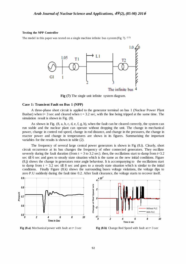
Testing the NPP Controller
The model in this paper was tested on a single machine infinite bus system (Fig 7). (13)
Fig (7) The single unit infinite system diagram.
Case 1: Transient Fault on Bus 1 (NPP)
A three-phase short circuit is applied to the generator terminal on bus 1 (Nuclear Power Plant Busbar) when t= 3 sec and cleared when t = 3.2 sec, with the line being tripped at the same time. The simulation result is shown in Fig. (8).
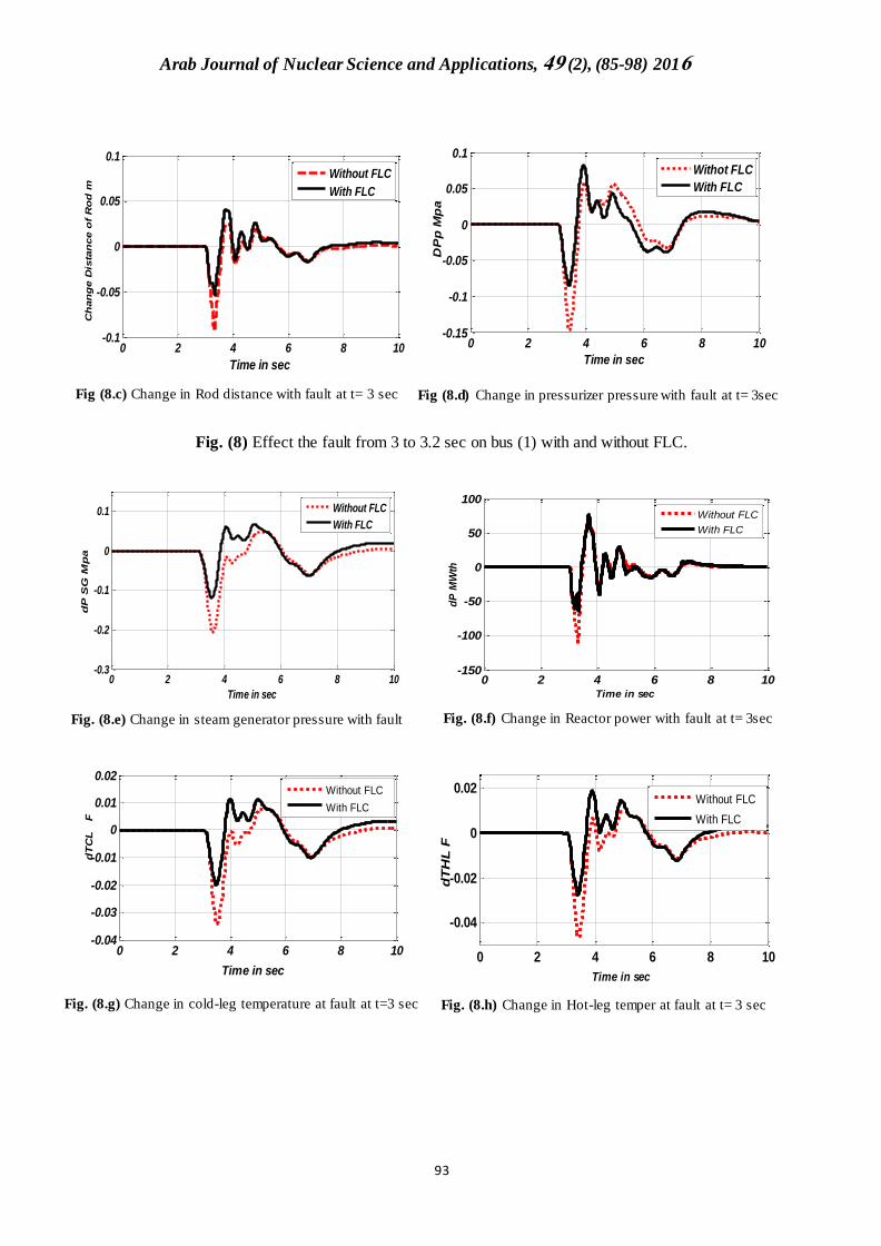
As shown in Fig. (8, a, b, c, d, e, f, g, h), when the fault can be cleared correctly, the system can run stable and the nuclear plant can operate without dropping the unit. The change in mechanical power, change in control rod speed, change in rod distance, and change in the pressures, the change in reactor power and change in temperatures are shows in its figures. Summarizing the important variables for the results is shown in table (2).
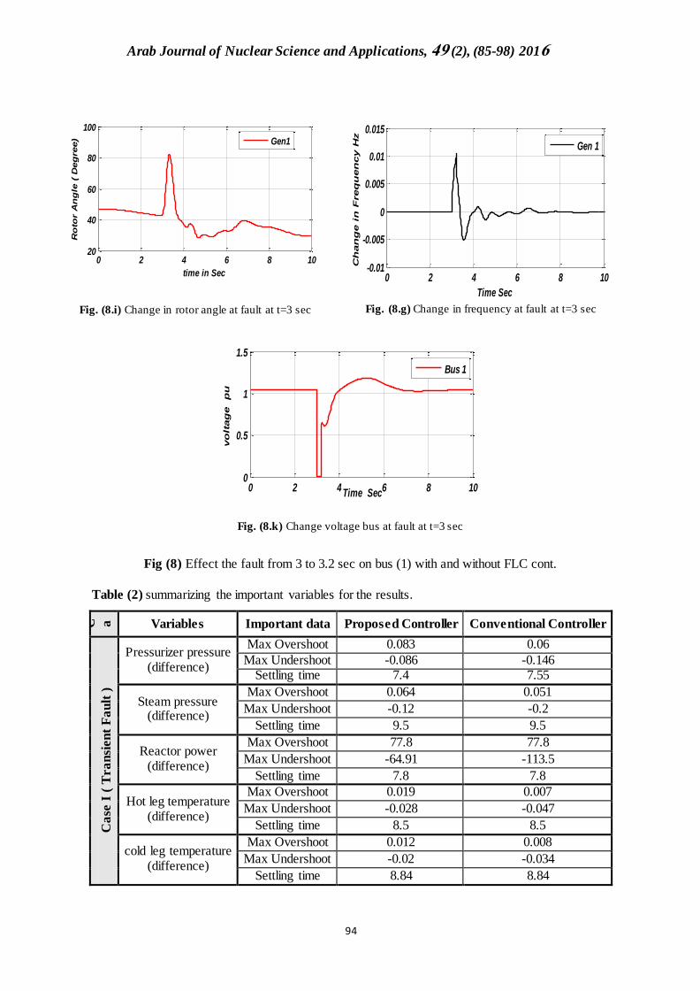
The frequency of several large central power generators is shown in Fig (8.i). Clearly, short circuit occurrence at its bus changes the frequency of other connected generators. They oscillate severely during the fault duration (from t = 3 to 3.2 sec). then, the oscillations start to damp from t=3.2 sec till 6 sec and goes to steady state situation which is the same as the new initial conditions. Figure (8.j) shows the change in generators rotor angle behaviour. It is accompanying to the oscillations start to damp from t = 3.2 sec till 8 sec and goes to a steady state situation which is similar to the initial conditions. Finally Figure (8.k) shows the surrounding buses voltage violations, the voltage dips to zero P.U suddenly during the fault time 0.2. After fault clearance, the voltage starts to recover itself.
Fig (8.a) Mechanical power with fault at t= 3 sec
Fig (8.b) Change Rod Speed with fault at t= 3 sec
0 2 4 6 8 100.5
0.6
0.7
0.8
0.9
Time in Sec
Pm
ec
h
0 2 4 6 8 10-4
-2
0
2
4x 10
-3
Time in sec
Ch
an
ge o
f R
od
Sp
eed
m/s
Without FLC
With FLC
Arab Journal of Nuclear Science and Applications, 94 (2), (85-98) 2016
89
Fig (8.c) Change in Rod distance with fault at t= 3 sec
Fig (8.d) Change in pressurizer pressure with fault at t= 3sec
Fig. (8) Effect the fault from 3 to 3.2 sec on bus (1) with and without FLC.
Fig. (8.e) Change in steam generator pressure with fault
Fig. (8.f) Change in Reactor power with fault at t= 3sec
Fig. (8.g) Change in cold-leg temperature at fault at t=3 sec
Fig. (8.h) Change in Hot-leg temper at fault at t= 3 sec
0 2 4 6 8 10-0.1
-0.05
0
0.05
0.1
Time in sec
Ch
an
ge D
ista
nce o
f R
od
m
Without FLC
With FLC
0 2 4 6 8 10-0.15
-0.1
-0.05
0
0.05
0.1
Time in sec
DP
p M
pa
Withot FLC
With FLC
0 2 4 6 8 10-0.3
-0.2
-0.1
0
0.1
Time in sec
dP
SG
Mp
a
Without FLC
With FLC
0 2 4 6 8 10-150
-100
-50
0
50
100
Time in sec
dP
MW
th
Without FLC
With FLC
0 2 4 6 8 10-0.04
-0.03
-0.02
-0.01
0
0.01
0.02
Time in sec
dT
CL
F
Without FLC
With FLC
0 2 4 6 8 10
-0.04
-0.02
0
0.02
Time in sec
dT
HL
F
Without FLC
With FLC
Arab Journal of Nuclear Science and Applications, 94 (2), (85-98) 2016
89
Fig. (8.i) Change in rotor angle at fault at t=3 sec Fig. (8.g) Change in frequency at fault at t=3 sec
Fig. (8.k) Change voltage bus at fault at t=3 sec
Fig (8) Effect the fault from 3 to 3.2 sec on bus (1) with and without FLC cont.
Table (2) summarizing the important variables for the results.
C a se
Variables Important data Proposed Controller Conventional Controller
Ca
se I
( T
ra
nsi
en
t F
au
lt )
Pressurizer pressure (difference)
Max Overshoot 0.083 0.06
Max Undershoot -0.086 -0.146 Settling time 7.4 7.55
Steam pressure (difference)
Max Overshoot 0.064 0.051
Max Undershoot -0.12 -0.2
Settling time 9.5 9.5
Reactor power (difference)
Max Overshoot 77.8 77.8
Max Undershoot -64.91 -113.5
Settling time 7.8 7.8
Hot leg temperature (difference)
Max Overshoot 0.019 0.007
Max Undershoot -0.028 -0.047
Settling time 8.5 8.5
cold leg temperature (difference)
Max Overshoot 0.012 0.008
Max Undershoot -0.02 -0.034
Settling time 8.84 8.84
0 2 4 6 8 1020
40
60
80
100
time in Sec
Ro
tor A
ng
le (
Deg
ree)
Gen1
0 2 4 6 8 10-0.01
-0.005
0
0.005
0.01
0.015
Time Sec
Ch
an
ge i
n F
req
uen
cy H
z
Gen 1
0 2 4 6 8 100
0.5
1
1.5
Time Sec
vo
ltag
e
pu
Bus 1
Arab Journal of Nuclear Science and Applications, 94 (2), (85-98) 2016
88
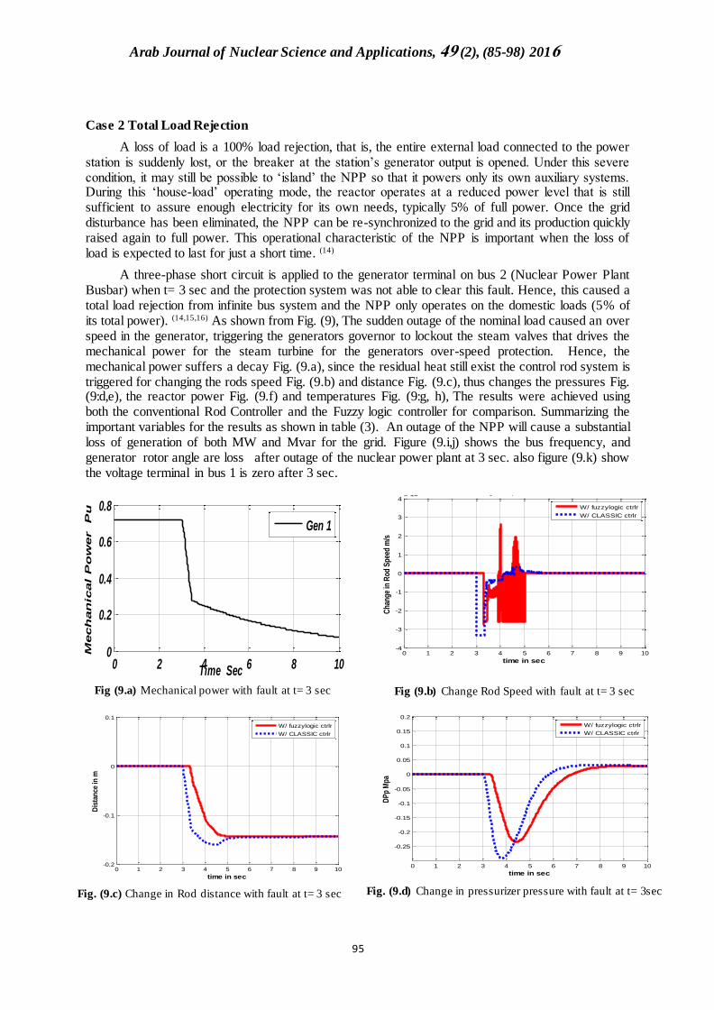
Case 2 Total Load Rejection
A loss of load is a 100% load rejection, that is, the entire external load connected to the power station is suddenly lost, or the breaker at the station’s generator output is opened. Under this severe condition, it may still be possible to ‘island’ the NPP so that it powers only its own auxiliary systems. During this ‘house-load’ operating mode, the reactor operates at a reduced power level that is still sufficient to assure enough electricity for its own needs, typically 5% of full power. Once the grid disturbance has been eliminated, the NPP can be re-synchronized to the grid and its production quickly raised again to full power. This operational characteristic of the NPP is important when the loss of load is expected to last for just a short time. (14)
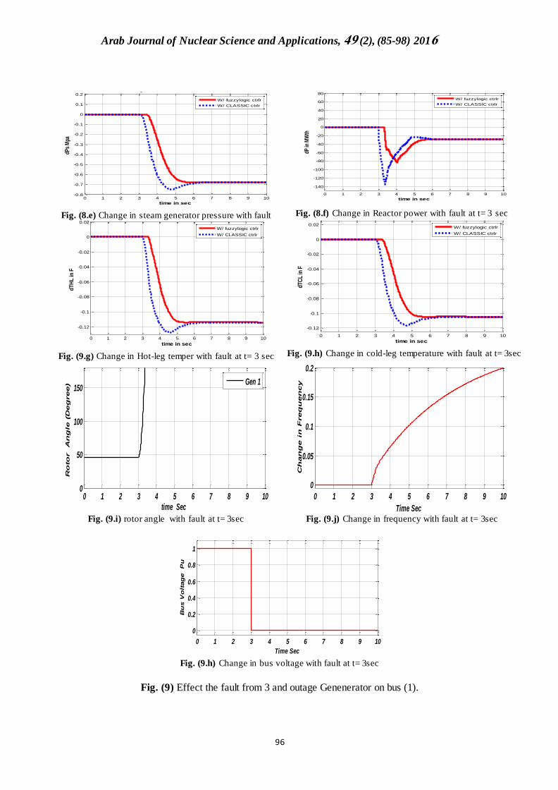
A three-phase short circuit is applied to the generator terminal on bus 2 (Nuclear Power Plant Busbar) when t= 3 sec and the protection system was not able to clear this fault. Hence, this caused a total load rejection from infinite bus system and the NPP only operates on the domestic loads (5% of its total power). (14,15,16) As shown from Fig. (9), The sudden outage of the nominal load caused an over speed in the generator, triggering the generators governor to lockout the steam valves that drives the mechanical power for the steam turbine for the generators over-speed protection. Hence, the mechanical power suffers a decay Fig. (9.a), since the residual heat still exist the control rod system is triggered for changing the rods speed Fig. (9.b) and distance Fig. (9.c), thus changes the pressures Fig. (9:d,e), the reactor power Fig. (9.f) and temperatures Fig. (9:g, h), The results were achieved using both the conventional Rod Controller and the Fuzzy logic controller for comparison. Summarizing the important variables for the results as shown in table (3). An outage of the NPP will cause a substantial loss of generation of both MW and Mvar for the grid. Figure (9.i,j) shows the bus frequency, and generator rotor angle are loss after outage of the nuclear power plant at 3 sec. also figure (9.k) show the voltage terminal in bus 1 is zero after 3 sec.
Fig (9.a) Mechanical power with fault at t= 3 sec
Fig (9.b) Change Rod Speed with fault at t= 3 sec
Fig. (9.c) Change in Rod distance with fault at t= 3 sec
Fig. (9.d) Change in pressurizer pressure with fault at t= 3sec
0 2 4 6 8 100
0.2
0.4
0.6
0.8
Time Sec
Mech
an
ical P
ow
er P
u
Gen 1
0 1 2 3 4 5 6 7 8 9 10-4
-3
-2
-1
0
1
2
3
4x 10
-3
Ch
ang
e in
Ro
d S
pee
d m
/s
Change in Speed of Control Rod
time in sec
W/ fuzzylogic ctrlr
W/ CLASSIC ctrlr
0 1 2 3 4 5 6 7 8 9 10-0.2
-0.1
0
0.1
Dis
tan
ce in
m
Change in Distance of Rod m
time in sec
W/ fuzzylogic ctrlr
W/ CLASSIC ctrlr
0 1 2 3 4 5 6 7 8 9 10
-0.25
-0.2
-0.15
-0.1
-0.05
0
0.05
0.1
0.15
0.2
DP
p M
pa
Pressurizer Pressure
time in sec
W/ fuzzylogic ctrlr
W/ CLASSIC ctrlr
Arab Journal of Nuclear Science and Applications, 94 (2), (85-98) 2016
88
Fig. (8.e) Change in steam generator pressure with fault
Fig. (8.f) Change in Reactor power with fault at t= 3 sec
Fig. (9.g) Change in Hot-leg temper with fault at t= 3 sec
Fig. (9.h) Change in cold-leg temperature with fault at t= 3sec
Fig. (9.i) rotor angle with fault at t= 3sec
Fig. (9.j) Change in frequency with fault at t= 3sec
Fig. (9.h) Change in bus voltage with fault at t= 3sec
Fig. (9) Effect the fault from 3 and outage Genenerator on bus (1).
0 1 2 3 4 5 6 7 8 9 10-0.8
-0.7
-0.6
-0.5
-0.4
-0.3
-0.2
-0.1
0
0.1
0.2
dPs
Mpa
Change in Steam Generation Pressure.
time in sec
W/ fuzzylogic ctrlr
W/ CLASSIC ctrlr
0 1 2 3 4 5 6 7 8 9 10
-140
-120
-100
-80
-60
-40
-20
0
20
40
60
80
dP in
MW
th
Change in power
time in sec
W/ fuzzylogic ctrlr
W/ CLASSIC ctrlr
0 1 2 3 4 5 6 7 8 9 10
-0.12
-0.1
-0.08
-0.06
-0.04
-0.02
0
0.02
dT
HL
in F
Change in hot leg temp.
time in sec
W/ fuzzylogic ctrlr
W/ CLASSIC ctrlr
0 1 2 3 4 5 6 7 8 9 10
-0.12
-0.1
-0.08
-0.06
-0.04
-0.02
0
0.02
dTC
L in
F
Change in cold leg Temp.
time in sec
W/ fuzzylogic ctrlr
W/ CLASSIC ctrlr
0 1 2 3 4 5 6 7 8 9 100
50
100
150
time Sec
Ro
to
r A
ng
le (D
eg
ree)
Gen 1
0 1 2 3 4 5 6 7 8 9 10
0
0.05
0.1
0.15
0.2
Time Sec
Ch
an
ge in
F
req
uen
cy
0 1 2 3 4 5 6 7 8 9 10
0
0.2
0.4
0.6
0.8
1
Time Sec
Bu
s V
olt
ag
e
Pu
Arab Journal of Nuclear Science and Applications, 94 (2), (85-98) 2016
88
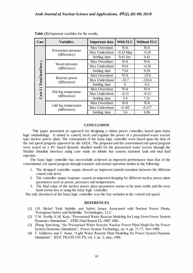
Table (3) Important variables for the results.
Case Variables Important data With FLC Without FLC C
ase
I (
To
tal
loa
d l
oss
)
Pressurizer pressure (difference)
Max Overshoot N/A N/A
Max Undershoot -0.23 Mpa -0.29
Settling time 9.41 Sec 9.41
Steam pressure (difference)
Max Overshoot N/A N/A
Max Undershoot N/A -0.29
Settling time 7.63 9.59
Reactor power (difference)
Max Overshoot N/A -23.6
Max Undershoot -53.7 -135.6
Settling time 6 6.5
Hot leg temperature (difference)
Max Overshoot N/A N/A
Max Undershoot -0.11 -0.13
Settling time 5.4 7.31
cold leg temperature (difference)
Max Overshoot N/A N/A
Max Undershoot -0.105 -0.117
Settling time 5.6 6.96
CONCLUSION
This paper presented an approach for designing a robust power controller, based upon fuzzy logic methodology. It aimed to control, track and regulate the power of a pressurized water reactor type nuclear power plant. The consequents of the fuzzy logic controller were based upon the data of the rod speed program approved by the IAEA. The proposed and the conventional rod speed program were tested on a PC based dynamic detailed model for the pressurized water reactor through the Matlab/ Simulink Interface using case study on infinite bus system: transient fault and total load rejection.
The fuzzy logic controller has successfully achieved an improved performance than that of the conventional rod speed program through transient and normal operation modes in the following:
1. The designed controller output showed an improved smooth transition between the different control rods level.
2. The controller output response caused an improved damping for different nuclear power plant parameters such as power, pressures and temperatures.
3. The final value of the nuclear power plant parameters seems to be more stable and the error band seems less at using the fuzzy logic controller.
The only drawback of the fuzzy logic controller was the fast variation in the control rod speed.
REFERENCES
(1) J.H. Bickel “Grid Stability and Safety Issues Associated with Nuclear Power Plants, “Evergreen Safety and Reliability Technologies, LLC
(2) T.W. Kerlin, E.M. Katz, “Pressurized Water Reactor Modeling for Long-Term Power System Dynamics Simulations”, EPRI Final Report EL-3087.1983.
(3) Zhang Xuecheng, “the Pressurized Water Reactor Nuclear Power Plant Model for the Power System Dynamics Simulation”, Power System Technology, no. 4, pp. 71-77, Nov 1990.
(4) T. Ichikawa and T. Inoue, “Light Water Reactor Plant Modeling for Power System Dynamic Simulation”, IEEE TRANS ON PS, vol. 3, no. 2, may, 1988.
Arab Journal of Nuclear Science and Applications, 94 (2), (85-98) 2016
85
(5) M. Si-Fodil, F. Guely, P. Siarry, and J.L. Tyran, “A Fuzzy Rule Base for the Control of a Nuclear Reactor”, EDK, Paris, France, 1998..
(6) D. Ruan, “Fuzzy Systems and Soft Computing in Nuclear Engineering”, Physica, New York, NY, USA, 2000.
(7) D. Ruan, “Safety regulations and fuzzy-logic control to nuclear reactors,” Mathware& Soft Computing, vol. 7, pp. 351–360, 2000
(8) X. Li and D. Ruan, “Comparative study of fuzzy control, PID control, and advanced fuzzy control for simulating a nuclear reactor operation,” International Journal of General Systems, vol. 29, no. 2, pp. 263–279, 2000.
(9) D. Ruan and J.S. Ben ı́tez-Read, “Fuzzy control for nuclear reactor operation-strengths, weaknesses, opportunities and threats,” Journal of Intelligent and Fuzzy Systems, vol. 16, no. 4, pp. 289–295, 2005.
(10) H. Zeng, “Controlling reactor power of CARR with fuzzy logic controller,” in Proceedings of the Intelligent Systems and Knowledge Engineering (ISKE ’07), Advances in Intelligent Systems Research, 2007
(11) J.S. Benitez-Read, T. Rivero-Gutierrez, D. Ruan, C. L. Ramirez-Chavez, R. Lopez-Callejas, and J. O. Pacheco-Sotelo, “User interface for intelligent control schemes in a TRIGA mark III reactor,” International Journal of Nuclear Knowledge Management , vol. 2, no. 3, pp. 268–284, 2007.
(12) Fazekas, Cs., “A Simple Dynamic Model of the Primary Circuit in VVER Plants for Controller Design Purposes”, Nuclear Engineering and Design 237, pp. 1071–1087 (2007).
(13) H. Gao. “A Detailed Nuclear Power Plant Model for Power System Analysis Based on PSS/E.” IEEE Transactions on Power Systems, 2006.
(14) U.S. Nuclear Regulatory Commission Office of Nuclear Regulatory Research Washington, NUREG-1431, Volume 2, Revision 4 “Standard Technical Specifications, Westinghouse Plants”, 2012-04.
(15) IAEA "Interfacing Nuclear Power Plants with the Electric Grid: the Need for Reliability amid Complexity". https://www.iaea.org/About/Policy/GC/GC53/GC53InfDocuments/English/gc53inf-3-att5_en.pdf
(16) Hu Xiuehao and Zhang Xuecheng "Pressurized water reactor nuclear power plant modeling and the midterm dynamic simulation after nuclear power plant has been introduced into power system", IEEE TENCON'93 / Beijng.