Embed Size (px)
Citation preview

* Corresponding author, tel: +234 – 806 – 688 – 7235
DESIGN AND IMPLEMENTATION OF A DENSITY-BASED TRAFFIC LIGHT CONTROL
WITH SURVEILLANCE SYSTEM
Y. N. Udoakah1,* and I. G. Okure2
1,2 DEPT. OF ELECTRICAL/ELECTRONICS & COMPUTER ENGR’, UNIVERSITY OF UYO, UYO, AKWA IBOM STATE. NIGERIA
E-mail addresses: [email protected], 2 [email protected]
ABSTRACT
Traffic congestion especially at road intersections is becoming an issue for which road traffic users contend with daily.
The conventional traffic light applies a fixed logic of allocating equal “GO” time to lanes of traffic at road intersections irrespective of the density of traffic on each lane. Using the PIC18F4550 microcontroller interfaced with infrared
sensors, a new traffic light control system was developed to ease the flow of traffic at a particular troubled spot in Uyo Metropolis (Abak Road, Udo Eduok, Udo Obio streets intersection) in Akwa Ibom State, Nigeria. Simulation of the
proposed design was performed using the Proteus Software while implementation was carried out on a prototype. Performance evaluation of the prototype implemented showed that the 4 arrays (IR Transmitter and Receiver) of
infrared sensors interfaced with the microcontroller using AND gates and strategically positioned to read the density of traffic on each lane at the intersection triggered when a vehicle comes between the transmitter and the receiver.
Obtaining inputs from these sensors together with the logic from the microcontroller, a new traffic light control system was developed capable of controlling traffic based on the density of each lane of traffic. Results obtained from
simulation and implementation of the design indicates that the traffic control system with the PIC18F4550 microcontroller and the infrared sensors gives a better performance compared to the conventional traffic light control
system.
Keywords: Road traffic density, Traffic light, Uyo metropolis, ‘+’ road intersection, Proteus.
1. INTRODUCTION
The constant movement of people from rural to urban
areas in search of greener pastures has resulted in
urban population explosion and over-stretched
infrastructures. One of such over-stretched
infrastructure is the road, a situation which has
culminated to increased traffic. Although traffic lights
have always been used for controlling the movement of
traffic (pedestrian or automobile), traffic management
in major cities around the world has continued to be a
subject of concern. In an attempt to tackle the traffic
management concern, various designs have either been
proposed or implemented. The first of such installation
dates back to 1868 [1-2]. Since then, modern day
civilization has found application in its use for
managing traffic in cities in the absence of traffic
wardens or officers; though with innovations, changes
have been made in signs, but the working principle for
traffic and pedestrian control remains the same.
With the rapid growth in the population of our cities,
the busy nature of our roads and the need to maximize
one’s time, there arise a need for a more dynamic,
systematic and efficient traffic management scheme-
one which seeks to reduce unnecessary congestion and
lawlessness resulting from undue delays. It would be
imperative that a new design be developed so as to
enhance the flow and control of traffic using the density
of vehicles on a particular lane by automatically
assigning the left-over time in an idle lane to the lane
with more traffic density, hence, reducing traffic
congestion in those lanes and at the same time capture
the vehicle license number plate of road users who
disobey traffic using the surveillance system. The aim
of this work is therefore to design a density based
traffic light control system with a surveillance
monitoring system using the technology which is
similar to that of [1].
Studies have been carried out all with the aim of
improving the traffic management system; [3]
described the modeling and implementation of an
advanced traffic signal controller within a microscopic
simulation environment, MITSIMLab. The controller
was designed with a generic and flexible logic that
allowed it to simulate control strategies including both
Nigerian Journal of Technology (NIJOTECH)
Vol. 36, No. 4, October 2017, pp. 1239 – 1248
Copyright© Faculty of Engineering, University of Nigeria, Nsukka, Print ISSN: 0331-8443, Electronic ISSN: 2467-8821
www.nijotech.com
http://dx.doi.org/10.4314/njt.v36i4.34

DESIGN AND IMPLEMENTATION OF A DENSITY-BASED TRAFFIC LIGHT CONTROL WITH SURVEILLANCE SYSTEM, Y. N. Udoakah & I. G. Okure
Nigerian Journal of Technology, Vol. 36, No. 4, October 2017 1240
isolated and coordinated intersection control, with
fixed-time and demand responsive logic;
implementation was carried out through a case study
in which it was applied to an urban arterial network in
Stockholm, Sweden. Similarly, [4] proposed the
optimization of the traffic light controller in a city using
ultrasonic sensor and microcontroller with fault
detection technique. Their proposal included an idea
for a dynamic and automatic traffic light control expert
system combined with a simulation mode. [5] designed
a traffic system that was capable of receiving signal
from emergency vehicles based on radio frequency
(RF) transmission and used the Programmable
Integrated Circuit (PIC) 16F877A microcontroller to
change the sequence back to the normal sequence
before the emergency mode was triggered. [6] designed
and implemented a traffic light system for road
intersection control; using image processing technique,
[7] proposed the design of an intelligent traffic control
system and noted that by continuously sensing and
adjusting the timing of traffic lights according to the
actual traffic load, the traffic congestion problem could
be solved. [8] employed a method proposed to reduce
heavy traffic congestion on the road by using PLC based
traffic diversion system; employing the working of
weight sensors whose output were fed to a PLC to
control the traffic diversion. It could be seen from
various studies that traffic system management is
critical and in view of this, there is need for the design
of a simple and cost effective traffic management
control system devoid of complexities but capable of
tackling most of the traffic concerns raised. This is what
this work seeks to achieve.
The major components used in implementing this
design are: the 5V DC power supply unit, infrared
sensors array and the PIC18F4550 microcontroller.
The PIC18F4550 a 40-pin PDIP with 20 pins on each
row and 256 bytes of EEPROM (Electrically Erasable
and Programmable Read Only Memory), 2KB of SRAM
(Static RAM) and 32KB of flash memory.
2. METHODOLOGY AND SYSTEM DESIGN
2.1 Design for Density Based Traffic Light Control
System
The approach to this design is realized through the
design and implementation of its input subsystem,
control unit (control program) and output subsystem.
The input subsystem is made of sensors, programmed
and implemented using some already existing
principles to achieve optimum performance. The
control unit is realized by a microcontroller-based
control program, which interprets the input and
qualifies it to produce a desired output. The block
diagram of the entire system as presented in Figure 1
shows the major components of the system.
Figure 1: Block diagram of the Density Based Traffic
Light Control System. These include:
Mains Supply
DC Power Supply
Sensors Arrays
Controller
Traffic Lights
Surveillance Camera
The block diagram was drawn so as to give a vivid
explanation of how the system works at a glance, thus;
the main supply provides 230VAC power which is
converted to 5VDC (VDD) by the DC power supply used
to power the sensor arrays, the controller, the
surveillance camera and traffic lights. The sensors
provide input to the controller which then performs
some logical operations to power the traffic lights as
output used for controlling traffic at road intersections.
Additionally for the proposed surveillance system, the
camera is interfaced with the controller to capture
license number plates of traffic defaulters for storage
and law enforcement purposes.
2.1.1 Choice of Sensors for Sensors Arrays
In choosing the sensors, the following features were
taken into consideration: accuracy, range, calibration,
resolution and affordability. Although the infrared (IR)
sensors are usually disturbed by noise in the
surrounding such as radiations, ambient light etc., they
were used for this design because they are cheap and
readily available in the market and are easy to
interface.
2.1.2 Choice of Microcontroller and Peripherals
Although the microcontroller PIC18F4550 has a few
disadvantages relating to its possession of a single
accumulator, but it was chosen because of the following
features noted in [9]:
Most effective and efficient microcontroller to be
used to accomplish the objective of the design.
Low cost, low percentage of faulty rate and very
consistent.
DESIGN AND IMPLEMENTATION OF A DENSITY-BASED TRAFFIC LIGHT CONTROL WITH SURVEILLANCE SYSTEM, Y. N. Udoakah & I. G. Okure
Nigerian Journal of Technology, Vol. 36, No. 4, October 2017 1241
More pins available for use in implementation of
the design features.
Very fast because of its RISC architecture.
Low power consumption and ease of
programming.
Ease of interfacing of an analog device without
any extra circuitry.
The pin description of the microcontroller is shown in
Table 1 while Figure 2 shows the interfacing of the
microcontroller with the peripherals. The 40 pins of
PIC18F4550 shown in Figure 3 are divided into 5 ports.
Out of which, 35 pins are Input-Output pins which can
be configured for general input or output by setting
registers associated with them.
Table 1: Ports and pin-outs on PIC18F4550.
Ports Number of Pins Pin Names
PORT A 7 RA0-RA6
PORT B 8 RB0-RB7
PORT C 7 RC0-RC2, RC4-RC7
PORT D 7 RD0-RD7
PORT E 4 RE0-RE3
Figure 2: Interfacing PIC18F4550.
Figure 3: Pin layout of PIC18F4550 [10].
Each port in the microcontroller is associated with
three 8 bit registers [10] for IO operations.
TRISX (8 bit): where X represents the name of the
ports. (A, B, C, D, E, etc). This register assigns the
direction of the pins (Input or Output). For
example “TRISB = 0xF0”, will set all the pins in
port B to Output.
LATX (8 bit): The latch registers reads and
modifies the write operation on the value of I/O
pin and stores the output data that is to be passed
on to the external hardware.
PORTX (8 bit): Reads the device level, stores the
input level of the pins and registers the input
signal from the external device if the pin is
configured as input.
2.1.3 Choice of the Crystal Oscillator The crystal oscillator in Figure 2 used in this design
for the interfacing of the microcontroller is of the
frequency 4MHz as recommended by the manufacturer
of the microcontroller.
From the values given by [11], a 4MHz
crystal oscillator should have the following
values;
= 00 , = 00 , = 0.0
The series-resonant frequency when the inductive
reactance is equal to the capacitive reactance can
be calculated using Eq. (1) below;
=
√ =
√ 00 0 0.0 0
= . 0
2.1.4 Choice of Ceramic Capacitor
The value of capacitors C1 and C2 in Figure 2 is 22pF
which falls within the range of 0 0
recommended by the microcontroller manufacture.
The capacitance of the capacitor can be found using Eq.
(2) thus:
=
= . 0 ⁄ = 0.0 =
0
= . 0 0.0
0 = .
2.1.5 Choice of Pull-Up Resistors
The resistor R1 in Figure 2 is a pull up resistor which is
connected between a signal conductor and a positive
power supply voltage VDD to ensure that the signal will
be a valid logic level. The value of the resistor is
determined by the manufacturer of the
microcontroller, thus, 0K was used.
2.1.6 Choice of Traffic Light Indicators
Just like the conventional traffic light indicator as
shown in Figure 4, this design controls traffic using

DESIGN AND IMPLEMENTATION OF A DENSITY-BASED TRAFFIC LIGHT CONTROL WITH SURVEILLANCE SYSTEM, Y. N. Udoakah & I. G. Okure
Nigerian Journal of Technology, Vol. 36, No. 4, October 2017 1242
three light emitting diodes, ‘GREEN’, ‘YELLOW’ and
‘RED’, each having their usual meaning of ‘GO’, ‘READY’
and ‘STOP’ respectively. They are controlled by the
control buses of the microcontroller depending on the
logical decisions taken by the controller to control the
lanes of traffic according to their densities.
Figure 4: Traffic light indicators.
Figure 5: Road layout at point of implementation in Uyo
Metropolis.
3. IMPLEMENTATION
3.1 Road Layout
For the implementation of this design, the Abak road,
Udobio and Udo Eduok Street axis in Uyo, Akwa Ibom
State, Nigeria was considered. The road layout for this
design is the “+” road intersection represented in
Figure 5 similar to the road layout used in [12-14].
The trouble spot was chosen and a model developed,
because of its constant traffic log-jamb. It was observed
that smaller streets like Udo Eduok and Udobio which
often times had little traffic were allotted equal ‘GO’
time when compared to the Abak Road a major
expressway.
3.1.2 Infrared Sensors Arrangement and
Implementation
Since the design is focused on sensing the traffic level
on each of the lanes of the road depending on the
density of each lane using infrared sensors, the
arrangement of the infrared sensor on the road layout
was positioned to perform this function.
The sensors are arranged on the median strip or road
reservation and on the drainage embankments for
Abak Road while using only the drainage embankments
or pavements for Udo Eduok and Udobio streets due to
the absence of the median strip in these streets. This
avoids the problem of probable interference with the
infrared rays from the transmitters by pedestrian and
stray animals. For each lane of traffic to be controlled,
four sensor arrays were deployed and arranged in an
array of four, two transmitters and two receivers as
shown in Figure 6.
Figure 6: Infrared transmitter and receiver positions at
location of implementation in Uyo Metropolis.
Figure 7(a): Flow chart of system.

DESIGN AND IMPLEMENTATION OF A DENSITY-BASED TRAFFIC LIGHT CONTROL WITH SURVEILLANCE SYSTEM, Y. N. Udoakah & I. G. Okure
Nigerian Journal of Technology, Vol. 36, No. 4, October 2017 1243
Figure 7(b): Flow chart of system.
3.2 ALGORITHM
The algorithm of the entire system is represented in the
flow chart. The flow chart begins in Figure 7(a) and
continues in Figure 7(b) for the purpose of legibility.
At the beginning of the flow chart, the system starts
and so does the RAM of the microcontroller. It clears
and initializes all the flags of the microcontroller.
Initially, all the stop flags are set which consequently
means that all the traffic light indicators for traffic
control for all the four lanes show a RED light which
stops all traffic at the beginning of its operation. The
states of all the sensor arrays on each lane of traffic is
then read and given as input to the microcontroller for
logical operations, the system then goes further to
assign operation serial number to each lane based on
their densities and the lane with the most density is

DESIGN AND IMPLEMENTATION OF A DENSITY-BASED TRAFFIC LIGHT CONTROL WITH SURVEILLANCE SYSTEM, Y. N. Udoakah & I. G. Okure
Nigerian Journal of Technology, Vol. 36, No. 4, October 2017 1244
assigned lane one. Therefore, the algorithm is
established and represented by a flowchart in Figure
7(a) and Figure 7(b). The flowchart is then translated
into C language and compiled using the Microsoft
Visual Studio IDE.
3.2.1 Design Simulation
The simulation of the circuit was performed using the
Proteus software. Due to the absence of an infrared
sensor representation in the Proteus software,
switches were used to represent the sensors on each
lane of traffic. A screenshot of the simulation procedure
for the circuit is shown in Figure 8. The switches
represent the infrared sensor [15] on each lane of
traffic and the LEDs which represent the traffic
indicator of each lane are divided into four and are
controlled by the pins of the microcontroller. The
microcontroller ports that were mainly used to control
the traffic light indicators are PORT C and PORT D.
For PORT C, the pins used are RC0, RC1, RC2, RC6 and
RC7 which control LEDs R1, Y1, G1, Y3, and G3
respectively while for PORT D, the pins used are RD0-
RD7 for controlling LEDs R2, Y2, G2, R3, R4, Y4, and G4
respectively. Accordingly, each lane of traffic has three
sets of LED bulbs for traffic control on each lane. Lane
one has R1, Y1 and G1; lane two has R2, Y2 and G2, lane
three has R3, Y3, and G3, lane four has R4, Y4 and G4
respectively; each colour of the LED having their usual
meaning in traffic control.
The switches that are in Figure 8 represent the infrared
sensors since there are no infrared representations in
Proteus for simulation. The switches which are labeled;
A11, A12, A21, A22 represent the infrared sensor array
for lane one, switches; B11, B12, B21, B22 represent
the infrared sensor array for lane two; switches C11,
C12, C21, C22 represent the infrared sensors for lane
three; switches D11, D12, D21, D22 represent the
infrared sensors for lane four. For lane one, switches
A11, A12, A21, A22 are interfaced with PORT A of the
microcontroller with pins RA0-RA3 respectively;
switches B11 and B12 for lane two are interfaced with
PORT A pins RA4 and RA5 respectively and switches
B21 and B22 are interface with PORT E, pins RE0 and
RE1 respectively; for lane three, switches C11, C12,
C21, C22 are interfaced with PORT B, pins RB0-RB3
respectively; for lane four, switches D11, D12, D21, D22
are interfaced with PORT B, pins RB4-RB7 respectively.
Infrared sensors are active low at normal state which in
this design portrays a scenario where there are no
obstacles between the transmitter and the receiver, but
if they are blocked, the receivers no longer receives
pings from the transmitter and are switched to the
active high state. This represents the function the
switches perform; when the switches are open, they
are in the active low state, but when they are closed,
they are in the active high state.
To mimic the real life scenario, switch A22 is the last
sensor, switch A21 is the second to the last sensor,
switch A12 is the second sensor and switch A11 is the
first sensor. When a car enters lane one, it blocks the
transmission to the receiver which is the sensor A22,
moving further it blocks sensor A21, A12 and then A11.
This swift process can be mimicked by closing switches
A22, A21, A12 and A11. This action switches the
sensors from active low to active high. This process
also applies for the other sensors in the other lanes of
traffic when a vehicle enters each lane respectively.
Each of the switches is grounded respectively.
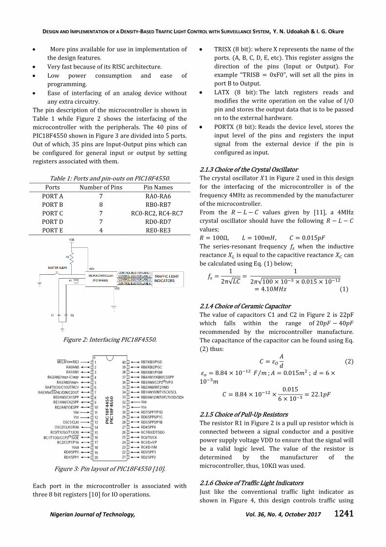
3.2.2 Complete Circuit Diagram
For the four lanes of traffic to be controlled,
requirements according to the aim as described in this
paper would demand more than 35 Input-Output pins.
For the aim to be achieved with the available pins of the
controller, the inputs from the four sensor arrays were
multiplexed using AND gates as shown in Figure 9
which is the complete PCB circuit layout as designed
using the Diptrace Schematic Capture Software; PORT
U8 represents the sensor input port for lane 1; and so
does PORT U9, U11, U12 represent the sensor input
port for lane 2, lane 3 and lane 4 respectively.
Additionally; PORT U10, U3, U4 and U5 represent the
output ports for the traffic lights of lane 1, lane 2, lane 3
and lane 4 respectively. AND gates are used to reduce
the complexity of the circuit. The surveillance camera is
interfaced with the microcontroller using PORT U14
which is the camera module, a serial communication
module as designed using the Diptrace software
because there is no representation of this in the
Proteus Software; where the connector for the camera
is placed and is operated in the 8-bit mode.
3.2.3 Mode of Operation
Once the traffic control commences operation, the
states of all the sensor arrays on each lane of traffic is
read and given as input to the microcontroller for
logical operations. The system assigns serial number to
each lane based on their density, where the lane with
the most density is assigned lane one. Accordingly, the
system sets the ready flag for lane one where the
YELLOW light shows; in preparation for the passing of
traffic in that lane and delays for a certain time before
giving the go signal with the GREEN light.

DESIGN AND IMPLEMENTATION OF A DENSITY-BASED TRAFFIC LIGHT CONTROL WITH SURVEILLANCE SYSTEM, Y. N. Udoakah & I. G. Okure
Nigerian Journal of Technology, Vol. 36, No. 4, October 2017 1245
Figure 8: Software Simulation on Proteus 7.
Going further, to implement the primary loop of the
flow chart; the system increments the counter where
the amount of time allotted for lane one is accounted
for; and takes a decision if the go time for lane one has
elapsed. If it has not, the system takes a decision on the
density of traffic on lane one by checking if the density
flag has been cleared; If no, the system increments the
counter again. After the density flag has been cleared
and time has elapsed, the system makes a decision
further to verify that the density flag has been cleared,
if not, additional time is added and the primary loop is
performed again. If the density flag for lane one is
cleared, it makes a decision by checking to see if either
lane one or any of the other three lanes are active, if
not, the program stops.
If lane one is the active lane, the ready flag for that lane
is set again and the YELLOW light shows in preparation
to stop traffic on that lane while simultaneously setting
the ready flag for lane two. Once lane one has been
stopped, the YELLOW light at lane two shows
indicating readiness and eventually the lane is passed
and the primary loop of the system could be performed
again. This process is repeated for all the other lanes
depending on which one is the active lane.
For the surveillance system, a 360º dome camera is
used and mounted on top of each traffic light. When the
GREEN light shows for a particular lane of traffic at any
instant of time, the camera automatically rotates and
faces the oncoming traffic but when the RED light
shows, the camera rotates and faces the opposite
direction that the vehicles are headed; such that if a car
beats the traffic light of the associated lane, the
surveillance camera captures the license number plate
and stores it in a memory. If a road user beats traffic
multiple times, the controller compares the captured
number plate with that which exists already in the
memory; it discards the captured image. The captured
image is sent to the memory in streams of 8-bit binary
code to match its 8-bit operating mode. The image
stored in the memory (RAM or EPROM) can be copied
to a removable storage device and given to law
enforcement agencies. All these operations are
performed by the logic operations carried out by the
microcontroller through series of codes embedded in
the controller.
DESIGN AND IMPLEMENTATION OF A DENSITY-BASED TRAFFIC LIGHT CONTROL WITH SURVEILLANCE SYSTEM, Y. N. Udoakah & I. G. Okure
Nigerian Journal of Technology, Vol. 36, No. 4, October 2017 1246
Figure 9: Complete Circuit Diagram.

DESIGN AND IMPLEMENTATION OF A DENSITY-BASED TRAFFIC LIGHT CONTROL WITH SURVEILLANCE SYSTEM, Y. N. Udoakah & I. G. Okure
Nigerian Journal of Technology, Vol. 36, No. 4, October 2017 1247
Figure 10: Stages of prototype implementation: (a) Microcontroller circuit mounted and soldered on Vero Board.
(b) Control unit of system enclosed in box. (c) Density based traffic light control system. (d) Density based traffic
light control system view through one of the lanes. (e) Density based traffic light control system in operation.
4. CONCLUSION
In this design work, a density based traffic light control
system was developed for traffic control at ‘+’ road
intersection to reduce unnecessary time wastage and
minimize road traffic casualties which the existing
conventional traffic light control system has failed to
achieve. As demonstrated by the test results in the
simulation and the prototype implementation as shown
in Figure 10 (a-e), the design has shown that the
system developed is a viable tool for traffic control and
the incorporation of a surveillance system would help
reduce road casualties caused by road users who

DESIGN AND IMPLEMENTATION OF A DENSITY-BASED TRAFFIC LIGHT CONTROL WITH SURVEILLANCE SYSTEM, Y. N. Udoakah & I. G. Okure
Nigerian Journal of Technology, Vol. 36, No. 4, October 2017 1248
ignore traffic signals. Lastly, the objectives of the design
were achieved. This paper has presented a means of
controlling traffic at ‘+’ road intersection using infrared
sensors with an embedded microcontroller chip.
Specifically, it demonstrates a working software
solution for controlling traffic based on the density of
traffic on each lane at the intersection. It provides a
means of succor away from the conventional traffic
light associated with even timing of lanes of traffic
irrespective of the number of vehicles on the lanes per
kilometer which is the density associated with that
lane. This project as resourceful as it has proven to be
can be improved upon by; the incorporation of
renewable energy sources for 24 hours performance of
the system. The system could also be designed to
transmit captured vehicle plate numbers of defaulters
in real time to relevant traffic agencies. Lastly, the
design can be modified to control more than four lanes
of traffic.
5. ACKNOWLEDGEMENT
The authors would like to thank Mr. Iyakkensemse
Okon for his immense contributions.
6. REFERENCES
[1] Day, L. and McNeil, I. Biographical dictionary of the history of technology, Taylor and Francis, 1996.
[2] Moyer, S. “Mr. Trafficlight”. Motor News. Automobile Club of Michigan: pp.14-15, 1947.
[3] Angus, P. D. ‘Modeling of Traffic Signal Control and Transit Signal Priority’. Massachusetts Institute of Technology, 2001.
[4] Ashish, J., Manisha, M., Harish, V. and Amrita R. “Traffic Density Measurement based On-road Traffic Control using Ultrasonic Sensors and GSM Technology”, in proc. AEEE 4th International Conference on Emerging Trends in Engineering and Technology, Kurushetra, Haryana, India, October 25-27, 2013, pp. 778-786.
[5] Hashim, N. M., Jaafar, A. S., Ali, N.A., Salahuddin, L., Mohamad, N. R. and Ibrahim, M. A. “Traffic Light Control System for Emergency Vehicles Using Radio Frequency”, ISOR Journal of Engineering, 3(7), pp. 43-52, 2013.
[6] Ganiyu, R. A., Arulogun, O. T. and Okediran, O. O. “Development of a Microcontroller Based Traffic Light System for Road Intersection Control”, International Journal of Scientific and Technology Research, 3(5), pp. 209-212, 2014.
[7] Kavya, P. W. and Joythi, S. “Traffic Light Control System Using Image Processing”, International Journal of Innovative Research in Computer and Communication Engineering, 2(5), pp. 288-292, 2014.
[8] Mohit, D. S., Prema, Shubhendu, S., Sumedha, S. and Utkarsh, T. “Smart Traffic Control System Using PLC and SCADA”, International Journal of Innovative Research in Science, Engineering and Technology, 1(2), pp. 169-172, 2012.
[9] Mani, T., Kumar, A. N., Dhanapal, M., Kumar, A. S., Hemalatha, R. and Vinodhini, I. “Density Based Traffic Light Control System”. International Journal of Advanced Research in Management, Architecture, Technology and Engineering, 2(9), pp. 334-339, 2016.
[10] Microchip (2007). 28/40/44-Pin, High Performance; Enhanced Flash, USB Microcontrollers with nanoWatt Technology, PIC18F2455/2550/4455/4550 datasheet, Microchip Technology Inc., Arizona, USA.
[11] Mehta, V. K. and Rohit, M. Principles of Electronics. S. Chand and Company PVT. LTD., New Delhi, India, 1980.
[12] Malik, T. and Hongchi, S. “Adaptive Traffic Light Control with Wireless Control Networks”, in 4th IEEE Consumer Communications and Networking Conference, Las Vegas, Nevada, USA, January 11-13, 2007, pp. 187-191.
[13] Khalil, Y., Al-Karaki, J. and Ali, S. “Intelligent Traffic Light Control System Using Wireless Sensors Networks”, Journal of Information Science, Engineering and Technology, 26, pp. 753-768, 2010.
[14] Osigwe, U. C., Oladipo, O. F. and Onibere, E. A. “Design and Simulation of an Intelligent Traffic Control System”, International Journal of Advances in Engineering and Technology, 1(5), pp. 47-57, 2011.
[15] Sharma, E. P., Mishra, A. and Singh, K. “Density Based Intelligent Traffic Control System Using IR Sensors”, International Journal of Scientific Research, 4(5), pp. 3-4, 2015.


![[2010] Density Based](https://img.pdfslide.us/doc/110x75/577cc4481a28aba71198c6fe/2010-density-based.jpg)


![Powerpoint_presenttation[1] on Density Based Intelligent](https://img.pdfslide.us/doc/110x75/577c823e1a28abe054b008df/powerpointpresenttation1-on-density-based-intelligent.jpg)