Embed Size (px)
Citation preview
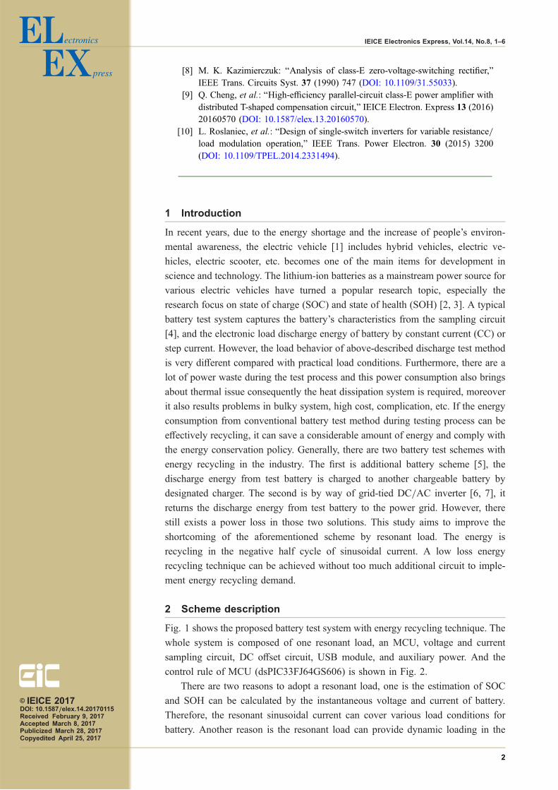
Design and implementation ofa battery test system withenergy recycling technique
Chang-Hua Lin1, Hwa-Dong Liu1, Yu-Liang Lin2a),and Tung-Chin Pan11 Department of Electrical Engineering, National Taiwan University of Science and
Technology, No. 43, Sec. 4, Keelung Rd., Da’an Dist. Taipei, Taiwan2 Institute of Nuclear Energy Research,
No. 1000, Wenhua Rd., Longtan Dist. Taoyuan, Taiwan
Abstract: In this study, a microcontroller-based battery test system for
power battery is realized. The system is composed by a microcontroller,
a sampling circuit, a human interface and a resonant load. The proposed
resonant load having wide-range slew-rate and continuous loading features
is used to verify the dynamic characteristics of the power battery thus can
recycle energy in diagnostic process. Furthermore, the system can provide
loading current according to battery specifications. The proposed system has
both low cost and portable feature. Finally, this work provides analysis of
operation principle, and test results to verify the theoretical feasibility.
Keywords: power battery, resonant load, energy recycling
Classification: Electron devices, circuits and modules
References
[1] X. Wang, et al.: “A multi-cell battery pack monitoring chip based on 0.35-µmBCD technology for electric vehicles,” IEICE Electron. Express 12 (2015)20150367 (DOI: 10.1587/elex.12.20150367).
[2] D. Gharavian, et al.: “ZEBRA battery SOC estimation using PSO-optimizedhybrid neural model considering aging effect,” IEICE Electron. Express 9(2012) 1115 (DOI: 10.1587/elex.9.1115).
[3] D. Park, et al.: “Fast battery charger MCU with adaptive PWM controller usingruntime tracking of polarization curve,” IEICE Electron. Express 13 (2016)20160131 (DOI: 10.1587/elex.13.20160131).
[4] Q. Zhang, et al.: “An area-efficient and high speed multiplexer for batterymonitor system,” IEICE Electron. Express 13 (2016) 20160120 (DOI: 10.1587/elex.13.20160120).
[5] C. H. Yang, et al.: “Switching-mode battery test system,” IEEE IS3C’14 (2014)(DOI: 10.1109/IS3C.2014.164).
[6] K. I. Hwu and Y. T. Yau: “Active load for burn-in test of buck-type DC-DCconverter with ultra-low output voltage,” IEEE APEC’08 (2008) (DOI: 10.1109/APEC.2008.4522788).
[7] H. Ma, et al.: “Energy recycling load system with a high gain DC-DC converterfor ultra low voltage power supplies,” IEEE ISIE’13 (2013) (DOI: 10.1109/ISIE.2013.6563619).
© IEICE 2017DOI: 10.1587/elex.14.20170115Received February 9, 2017Accepted March 8, 2017Publicized March 28, 2017Copyedited April 25, 2017
1
LETTER IEICE Electronics Express, Vol.14, No.8, 1–6
[8] M. K. Kazimierczuk: “Analysis of class-E zero-voltage-switching rectifier,”IEEE Trans. Circuits Syst. 37 (1990) 747 (DOI: 10.1109/31.55033).
[9] Q. Cheng, et al.: “High-efficiency parallel-circuit class-E power amplifier withdistributed T-shaped compensation circuit,” IEICE Electron. Express 13 (2016)20160570 (DOI: 10.1587/elex.13.20160570).
[10] L. Roslaniec, et al.: “Design of single-switch inverters for variable resistance/load modulation operation,” IEEE Trans. Power Electron. 30 (2015) 3200(DOI: 10.1109/TPEL.2014.2331494).
1 Introduction
In recent years, due to the energy shortage and the increase of people’s environ-
mental awareness, the electric vehicle [1] includes hybrid vehicles, electric ve-
hicles, electric scooter, etc. becomes one of the main items for development in
science and technology. The lithium-ion batteries as a mainstream power source for
various electric vehicles have turned a popular research topic, especially the
research focus on state of charge (SOC) and state of health (SOH) [2, 3]. A typical
battery test system captures the battery’s characteristics from the sampling circuit
[4], and the electronic load discharge energy of battery by constant current (CC) or
step current. However, the load behavior of above-described discharge test method
is very different compared with practical load conditions. Furthermore, there are a
lot of power waste during the test process and this power consumption also brings
about thermal issue consequently the heat dissipation system is required, moreover
it also results problems in bulky system, high cost, complication, etc. If the energy
consumption from conventional battery test method during testing process can be
effectively recycling, it can save a considerable amount of energy and comply with
the energy conservation policy. Generally, there are two battery test schemes with
energy recycling in the industry. The first is additional battery scheme [5], the
discharge energy from test battery is charged to another chargeable battery by
designated charger. The second is by way of grid-tied DC/AC inverter [6, 7], it
returns the discharge energy from test battery to the power grid. However, there
still exists a power loss in those two solutions. This study aims to improve the
shortcoming of the aforementioned scheme by resonant load. The energy is
recycling in the negative half cycle of sinusoidal current. A low loss energy
recycling technique can be achieved without too much additional circuit to imple-
ment energy recycling demand.
2 Scheme description
Fig. 1 shows the proposed battery test system with energy recycling technique. The
whole system is composed of one resonant load, an MCU, voltage and current
sampling circuit, DC offset circuit, USB module, and auxiliary power. And the
control rule of MCU (dsPIC33FJ64GS606) is shown in Fig. 2.
There are two reasons to adopt a resonant load, one is the estimation of SOC
and SOH can be calculated by the instantaneous voltage and current of battery.
Therefore, the resonant sinusoidal current can cover various load conditions for
battery. Another reason is the resonant load can provide dynamic loading in the
© IEICE 2017DOI: 10.1587/elex.14.20170115Received February 9, 2017Accepted March 8, 2017Publicized March 28, 2017Copyedited April 25, 2017
2
IEICE Electronics Express, Vol.14, No.8, 1–6
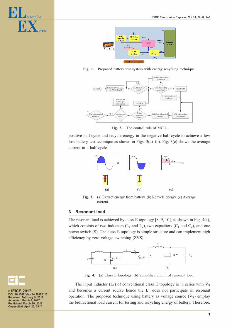
positive half-cycle and recycle energy in the negative half-cycle to achieve a low
loss battery test technique as shown in Figs. 3(a)–(b). Fig. 3(c) shows the average
current in a half-cycle.
3 Resonant load
The resonant load is achieved by class E topology [8, 9, 10], as shown in Fig. 4(a),
which consists of two inductors (L1 and L2), two capacitors (C1 and C2), and one
power switch (S). The class E topology is simple structure and can implement high
efficiency by zero voltage switching (ZVS).
The input inductor (L1) of conventional class E topology is in series with VS
and becomes a current source hence the L1 does not participate in resonant
operation. The proposed technique using battery as voltage source (VS) employ
the bidirectional load current for testing and recycling energy of battery. Therefore,
Fig. 1. Proposed battery test system with energy recycling technique.
Fig. 2. The control rule of MCU.
(a) (b) (c)
Fig. 3. (a) Extract energy from battery. (b) Recycle energy. (c) Averagecurrent
(a) (b)
Fig. 4. (a) Class E topology. (b) Simplified circuit of resonant load.
© IEICE 2017DOI: 10.1587/elex.14.20170115Received February 9, 2017Accepted March 8, 2017Publicized March 28, 2017Copyedited April 25, 2017
3
IEICE Electronics Express, Vol.14, No.8, 1–6
the L1 participates with resonant operation as shown in Fig. 4(b). Moreover, the
load (Ro) is short circuit in order to reduce power loss. For simplifying the circuit,
L2 and C2 are equivalent to a capacitive device Co, which can be represented as:
Co ¼ C2
1 � !2L2C2
ð1ÞAfterward we combine the Co and C1 to equivalent Ceq ¼ C1 þ Co and the resonant
frequency can be expressed as:
fr ¼ 1
2�ffiffiffiffiffiffiffiffiffiffiffiffiL1Ceq
p ð2Þ
The switching frequency fs of resonant load are set identical with resonant
frequency fr (in proposed case is 38 kHz). Based on the above design, the iL1 is
symmetrical in each half-cycle.
There are three distinct intervals in circuit operation.
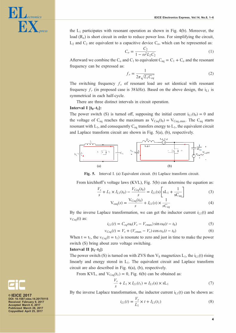
Interval I [t0–t1]:
The power switch (S) is turned off, supposing the initial current iL1ðt0Þ ¼ 0 and
the voltage of Ceq reaches the maximum as VCeqðt0Þ ¼ VCeq max. The Ceq starts
resonant with L1, and consequently Ceq transfers energy to L1, the equivalent circuit
and Laplace transform circuit are shown in Fig. 5(a), (b), respectively.
From kirchhoff’s voltage laws (KVL), Fig. 5(b) can determine the equation as:
Vs
sþ L1 � IL1ðt0Þ � VCeqðt0Þ
s¼ IL1ðsÞ sL1 þ 1
sCeq
� �ð3Þ
VceqðsÞ ¼ VCeqðt0Þs
þ IL1ðsÞ � 1
sCeqð4Þ
By the inverse Laplace transformation, we can get the inductor current iL1(t) and
vCeq(t) as:iL1ðtÞ ¼ Ceq!0ðVs � VcmaxÞ sin!0ðt � t0Þ ð5Þ
vCeqðtÞ ¼ Vs þ ðVcmax � VsÞ cos!oðt � t0Þ ð6ÞWhen t ¼ t1, the vCeqðt ¼ t1Þ is resonate to zero and just in time to make the power
switch (S) bring about zero voltage switching.
Interval II [t1–t2]:
The power switch (S) is turned on with ZVS then VS magnetizes L1, the iL1(t) rising
linearly and energy stored in L1. The equivalent circuit and Laplace transform
circuit are also described in Fig. 6(a), (b), respectively.
From KVL, and VCeqðt1Þ ¼ 0, Fig. 6(b) can be obtained as:
Vs
sþ L1 � IL1ðt1Þ ¼ IL1ðsÞ � sL1 ð7Þ
By the inverse Laplace transformation, the inductor current iL1(t) can be shown as:
iL1ðtÞ ¼ Vs
L1� t þ IL1ðt1Þ ð8Þ
(a) (b)
Fig. 5. Interval I. (a) Equivalent circuit. (b) Laplace transform circuit.
© IEICE 2017DOI: 10.1587/elex.14.20170115Received February 9, 2017Accepted March 8, 2017Publicized March 28, 2017Copyedited April 25, 2017
4
IEICE Electronics Express, Vol.14, No.8, 1–6
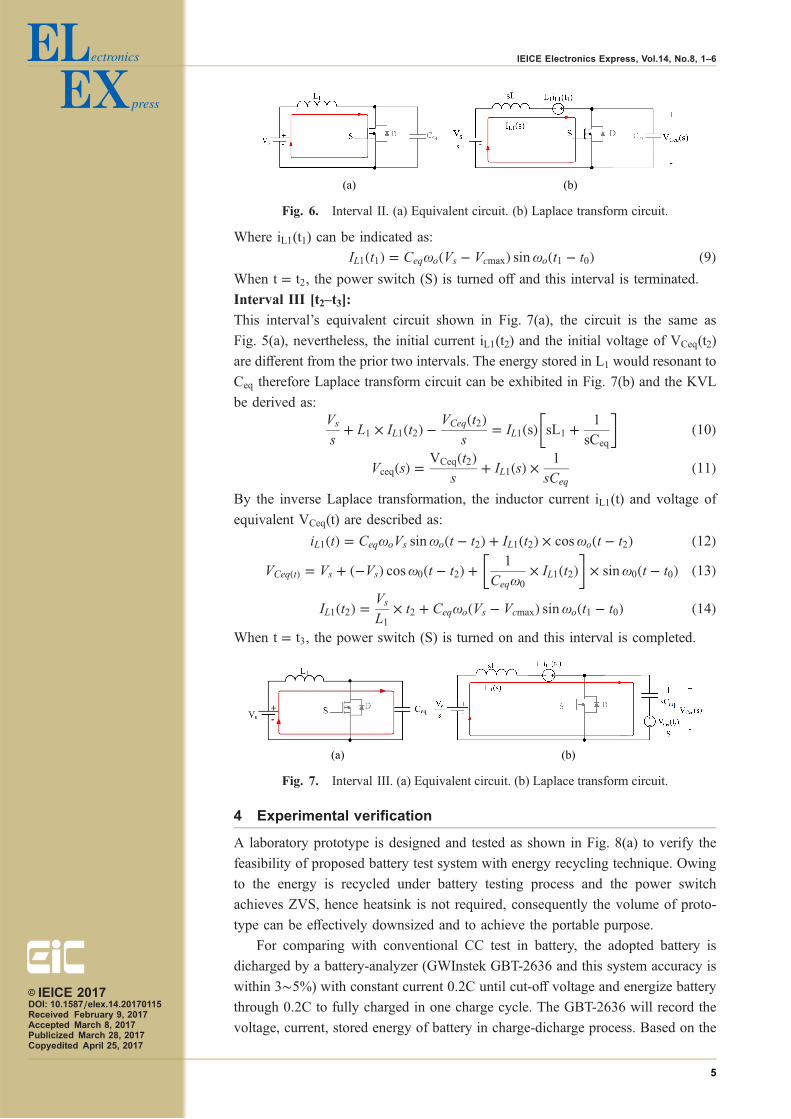
Where iL1(t1) can be indicated as:
IL1ðt1Þ ¼ Ceq!oðVs � VcmaxÞ sin!oðt1 � t0Þ ð9ÞWhen t ¼ t2, the power switch (S) is turned off and this interval is terminated.
Interval III [t2–t3]:
This interval’s equivalent circuit shown in Fig. 7(a), the circuit is the same as
Fig. 5(a), nevertheless, the initial current iL1(t2) and the initial voltage of VCeq(t2)
are different from the prior two intervals. The energy stored in L1 would resonant to
Ceq therefore Laplace transform circuit can be exhibited in Fig. 7(b) and the KVL
be derived as:Vs
sþ L1 � IL1ðt2Þ � VCeqðt2Þ
s¼ IL1ðsÞ sL1 þ 1
sCeq
� �ð10Þ
VceqðsÞ ¼ VCeqðt2Þs
þ IL1ðsÞ � 1
sCeqð11Þ
By the inverse Laplace transformation, the inductor current iL1(t) and voltage of
equivalent VCeq(t) are described as:
iL1ðtÞ ¼ Ceq!oVs sin!oðt � t2Þ þ IL1ðt2Þ � cos!oðt � t2Þ ð12ÞVCeqðtÞ ¼ Vs þ ð�VsÞ cos!0ðt � t2Þ þ 1
Ceq!0
� IL1ðt2Þ� �
� sin!0ðt � t0Þ ð13Þ
IL1ðt2Þ ¼ Vs
L1� t2 þ Ceq!oðVs � VcmaxÞ sin!oðt1 � t0Þ ð14Þ
When t ¼ t3, the power switch (S) is turned on and this interval is completed.
4 Experimental verification
A laboratory prototype is designed and tested as shown in Fig. 8(a) to verify the
feasibility of proposed battery test system with energy recycling technique. Owing
to the energy is recycled under battery testing process and the power switch
achieves ZVS, hence heatsink is not required, consequently the volume of proto-
type can be effectively downsized and to achieve the portable purpose.
For comparing with conventional CC test in battery, the adopted battery is
dicharged by a battery-analyzer (GWInstek GBT-2636 and this system accuracy is
within 3�5%) with constant current 0.2C until cut-off voltage and energize battery
through 0.2C to fully charged in one charge cycle. The GBT-2636 will record the
voltage, current, stored energy of battery in charge-dicharge process. Based on the
(a) (b)
Fig. 6. Interval II. (a) Equivalent circuit. (b) Laplace transform circuit.
(a) (b)
Fig. 7. Interval III. (a) Equivalent circuit. (b) Laplace transform circuit.
© IEICE 2017DOI: 10.1587/elex.14.20170115Received February 9, 2017Accepted March 8, 2017Publicized March 28, 2017Copyedited April 25, 2017
5
IEICE Electronics Express, Vol.14, No.8, 1–6
recorded experimental data to calculate the capacity of battery within a charging
interval is defined as Q1, and the remaining capacity of battery after a discharging
interval is defined as Q2, accordingly the energy loss is defined as Qloss. Then the
energy recycling rate is defined as:
�recycle ¼ Q2
Q1
% ð15ÞProposed resonant load is used to load sinusoidal current, therefore the energy is
sank and backed to battery in one cycle, only exits part of energy loss. From
Fig. 3(c) the average value of sinusoidal current in positive half-cycle is:
Iavg ¼
Z �
0
Im � sinð!tÞdð!tÞ�
¼ 2Im�
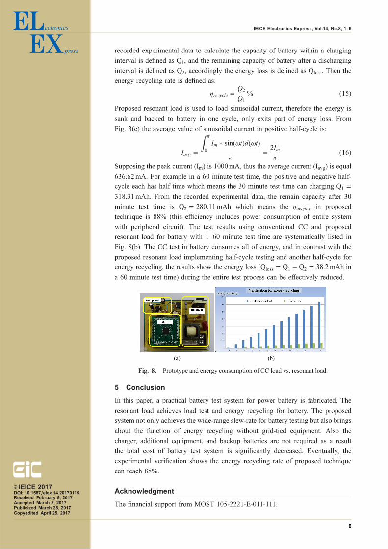
ð16ÞSupposing the peak current (Im) is 1000mA, thus the average current (Iavg) is equal
636.62mA. For example in a 60 minute test time, the positive and negative half-
cycle each has half time which means the 30 minute test time can charging Q1 ¼318:31mAh. From the recorded experimental data, the remain capacity after 30
minute test time is Q2 ¼ 280:11mAh which means the �recycle in proposed
technique is 88% (this efficiency includes power consumption of entire system
with peripheral circuit). The test results using conventional CC and proposed
resonant load for battery with 1–60 minute test time are systematically listed in
Fig. 8(b). The CC test in battery consumes all of energy, and in contrast with the
proposed resonant load implementing half-cycle testing and another half-cycle for
energy recycling, the results show the energy loss (Qloss ¼ Q1 � Q2 ¼ 38:2mAh in
a 60 minute test time) during the entire test process can be effectively reduced.
5 Conclusion
In this paper, a practical battery test system for power battery is fabricated. The
resonant load achieves load test and energy recycling for battery. The proposed
system not only achieves the wide-range slew-rate for battery testing but also brings
about the function of energy recycling without grid-tied equipment. Also the
charger, additional equipment, and backup batteries are not required as a result
the total cost of battery test system is significantly decreased. Eventually, the
experimental verification shows the energy recycling rate of proposed technique
can reach 88%.
Acknowledgment
The financial support from MOST 105-2221-E-011-111.
(a) (b)
Fig. 8. Prototype and energy consumption of CC load vs. resonant load.
© IEICE 2017DOI: 10.1587/elex.14.20170115Received February 9, 2017Accepted March 8, 2017Publicized March 28, 2017Copyedited April 25, 2017
6
IEICE Electronics Express, Vol.14, No.8, 1–6