Embed Size (px)
Citation preview
VOL. 11, NO. 5, MARCH 2016 ISSN 1819-6608
ARPN Journal of Engineering and Applied Sciences
©2006-2016 Asian Research Publishing Network (ARPN). All rights reserved.
www.arpnjournals.com
3176
DESIGN AND IMPLEMENTATION OF 3-D MULTI-BEAM ANTENNA AND FMCW S-BAND RADAR FOR FIRE CONTROL SYSTEM
J. Suryana, A. Y. Pinangkis and A. Nursyamsiah
Lab Telekomunikasi Radio dan Gelombang Mikro, Sekolah Teknik Elektro dan Informatika, Institut Teknologi Bandung, Jl. Ganesa 10 Bandung, Indonesia
E-Mail: [email protected]
ABSTRACT
This paper is to address a 3-dimensional affordable phased array antenna for multibeam surveillance and tracking radar to support a Fire Control System. This 2m x 2m x 2m phased array antenna system is implemented at S-band and equipped with multi-beam forming capability for 3D electronic scanning without mechanical motors. A beamformer based on two stage Butler matrix for azimuth and elevation control is implemented and integrated to 16 x 16 cross dipole array antenna. Furthermore, to emulate the gun turret functions, we also prepared a mini launcher model for testing purposes to determine the effectiveness of the Fire Control System to acquire, track and lock the target. Keywords: FMCW radar, phased array, microstrip, cross dipole, fire control system. INTRODUCTION
Fire Control Systems is science of offsetting the direction of fired weapon from the line of sight to the target in order to hit the target. There are two types of Fire Control Systems: tactical and technical. Tactical fire control is the ability to optimally engage threats with their weapons and technical fire control is the ability to detect, identify and acquire targets, including range, and provide an updated ballistic parameters. Today, Fire control systems become important component in battle ships, fighter aircraft, and also in modern airfield defence systems. There are three main components from a fire control system: radar, launcher or gun turret and computer. Radar of a Fire Control system measures the coordinates of a target and provides data which may be used to determine the target trajectory and to predict its future position. The radar is responsible to track the target and measure its range, bearing and speed. This target information is then forwarded to the computer for predicting the target position and its trajectory. This target position and trajectory information is sent to the launcher for directing and elevating the gun in accordance with the orders received from the computer. Figure-1 shows the main component of a Fire Control System.
Figure-1. Fire control system block diagram [1].
One of the most important subsystem in a fire control system is the multifunction radar, because it works as the sensing device for target detection, position locking, and make guidance for missiles to hit the target. This paper is to address a 3-dimensional affordable phased array-based antenna for multibeam surveillance and tracking radar to support a Fire Control System. Our research activities focus on: 1) design and implemention of a 16 x 16 x 4 sided large array antenna, which each antenna is connected to beam-former for providing 3D-scanning and tracking, 2) design and implemention of a short range FMCW radar and its interface to large-array antenna system and 3) design and implemention of a mini launcher as a gun turret model to emulate the real launcher for synchronization between information of target direction from radar and launcher direction. Each problem will be solved with these approaches: 1) S-band large array antenna will be composed of
smaller sub-array with 16 identical 4x4 crossed dipole antenna. Each sub-array has 16 simultaneous beam, therefore the total beams per side will be 256 beams.
2) S-band radar is designed based on low power FMCW waveform
3) mini launcher model uses dual motorized system to support azimuth and elevation movements
RESEARCH METHODOLOGY
This part describes the research methodology in detail. It provides a study of the process used in designing the prototype of 16 x 16 x 4 sided phased array antenna. It also discusses the details of the two stage Butler Matrix implementation of 3-D multibeam scanning with azimuth and elevation direction control. This part also covers the design process of S-band FMCW radar with low power and LPI features. At the end of this part, we will discuss about the mini launcher design to emulate the gun turret. Large array S-band antenna design
These are the problem solving methods we used in this research:
VOL. 11, NO. 5, MARCH 2016 ISSN 1819-6608
ARPN Journal of Engineering and Applied Sciences
©2006-2016 Asian Research Publishing Network (ARPN). All rights reserved.
www.arpnjournals.com
3177
2m x 2m x 2m large array design For 3D scanning and multi-target tracking, the
arrangement of 256 antennas must have a phase shifter circuit.
most of the phase shifter circuits are organized to build a multi-beam former system to support 3D scanning and multi-target tracking purpose.
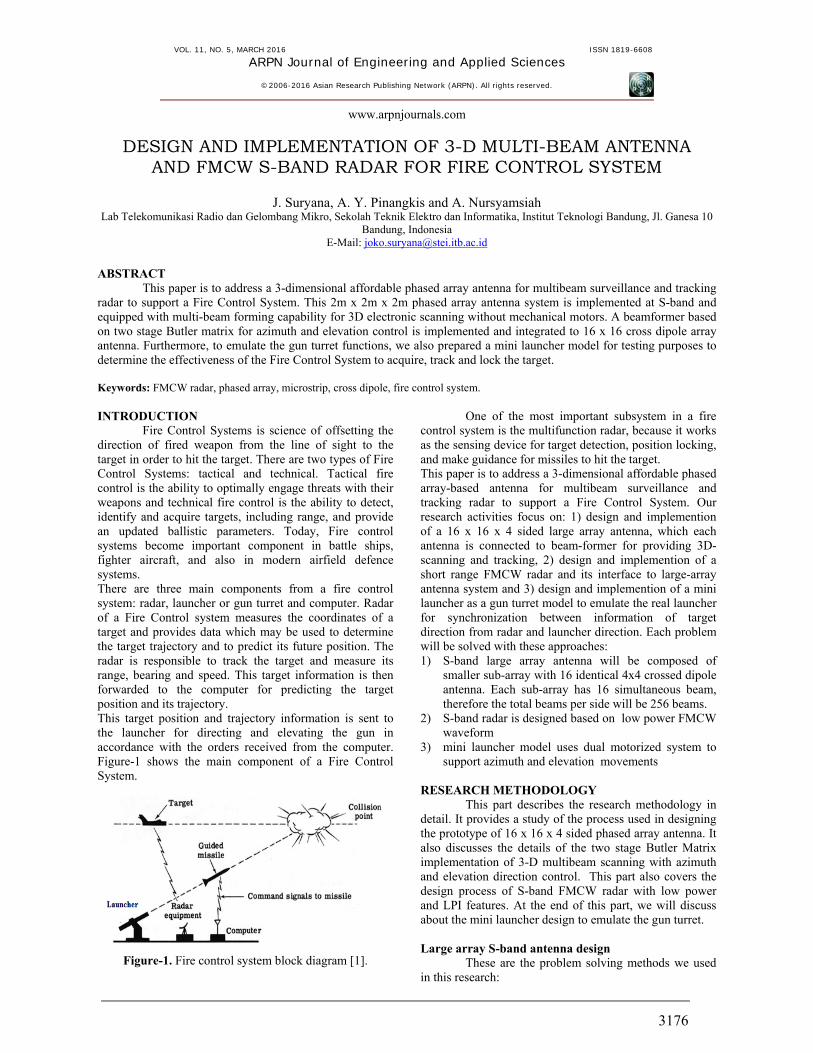
Figure-2 illustrates our proposed 4-sided phased-array antenna dome, which each side consists of 16x16 antenna array. Each side has 4 subarrays which uses cross dipole antenna elements for +45 degree and -45 degree polarization. These cross dipoles structure has circular polarization. In this case a planar dipole with its Marchand balun configuration is used as an antenna element and printed on 1.6 mm FR-4 material with relative permittivity about 4.6. Each side of dome is cover about 90 degree coverage with maximum 256 multibeam capability to support beam scanning and multi target tracking simultaneously.
Figure-2. Four-sided configuration of phased-array antenna dome.
For achieving longer detection range, antennas
are arranged in array with high number of elements. Each sub-array has 16 dB of gain, then for 16x16 array arrangement of these antennas will have 28 dB of gain. Another purpose of arranging more antenna elements is to make several beam-forms simultaneously. Figure-3 will show more details the proposed 16x16 antenna design.
For 3D scanning and multi-target tracking purpose, phase shifter circuit has to be placed on each element of 16x16 antenna array. In this research, for 3D scanning function, two 4x4 Butler Matrix [3] are needed both in vertical and also in horizontal direction. Figure-4 shows the design architecture of 4x4 Butler Matrix in 2-dimensional format. Butler matrix is a 2n x 2n network with 2n input, 2n output, 2n-1 log2 2n hybrid junctions and some phaseshifters. As the single layer microstrip printed circuit technique is used for the implementation of the matrix, there are several presences of cross lines in the planar layout, several crossovers are needed to isolate the signal.
In this study, two 4 x 4 Butler matrices have been designed to control the azimuth and elevation beam direction. Each of the matrix has four inputs and four outputs and it is implemented to excite an array of 4 cross dipole elements to produce four beams in desired directions.
Figure-3. Physical configuration of proposed 16x16 phased array antenna.
(a)
(b)
Figure-4. a) 2-stage 4x4 Butler Matrix Architecture and b) 2-stage 4x4 Butler Matrix simulation model.
S-Band FMCW radar design
In radar side, connection between S-Band FMCW Radar and phased-array antenna had been implemented. S-Band FMCW Radar implementation considers low power design but has LPI advantage. FMCW radar system design for this research is a modification of the FMCW radar that had previously been done by [4] which is a laptop based radar with center frequency 2.4 GHz and
VOL. 11, NO. 5, MARCH 2016 ISSN 1819-6608
ARPN Journal of Engineering and Applied Sciences
©2006-2016 Asian Research Publishing Network (ARPN). All rights reserved.
www.arpnjournals.com
3178
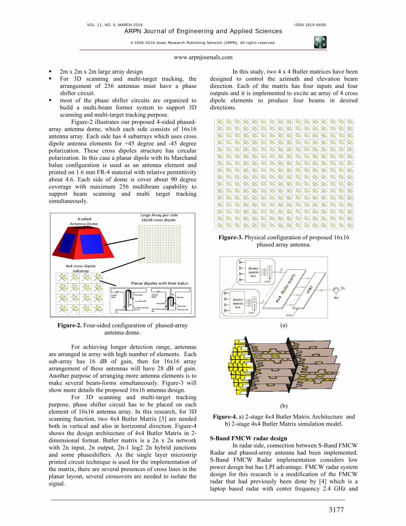
bandwidth of 300MHz. Whereas in this research the bandwidth is enlarged to 400 MHz. For radar integration with large array of 16x16 cross dipole, an interface is needed. The interface is the combination of RF switch and a T/R duplexer.
Figure-5. Antenna dome and S-Band FMCW Radar integration model diagram.
Mini Launcher design
The problem of controlling a gun-turret or launcher aim is very important in combat automation. The gun-turret or launcher control is achieved through proper combining the actuation of its azimuth and elevation inputs, which compensates for the perturbations due to motion of the military vehicle. In this research, launcher modelling will be solved by mechanical design of azimuth-elevation electric motor and gear system.
Figure-6. Dual-motorized mini launcher model. For driving those motors, a PWM (pulse width
modulation) controlled driver is used, managed by microprocessor’s control. Motor specification will consider the load’s weight of launcher. Figure-6 shows dual motorized mini launcher model design. RESULTS AND DISCUSSIONS Lab-Scale prototype of multibeam antenna system
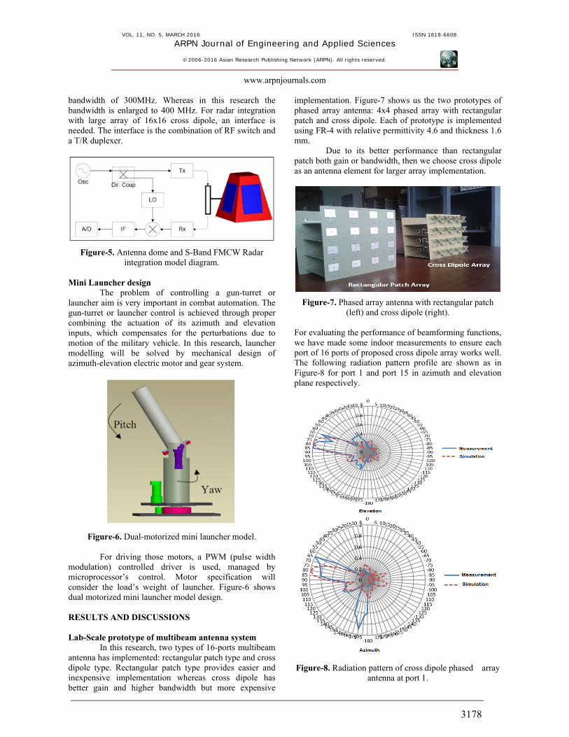
In this research, two types of 16-ports multibeam antenna has implemented: rectangular patch type and cross dipole type. Rectangular patch type provides easier and inexpensive implementation whereas cross dipole has better gain and higher bandwidth but more expensive
implementation. Figure-7 shows us the two prototypes of phased array antenna: 4x4 phased array with rectangular patch and cross dipole. Each of prototype is implemented using FR-4 with relative permittivity 4.6 and thickness 1.6 mm.
Due to its better performance than rectangular patch both gain or bandwidth, then we choose cross dipole as an antenna element for larger array implementation.
Figure-7. Phased array antenna with rectangular patch (left) and cross dipole (right).
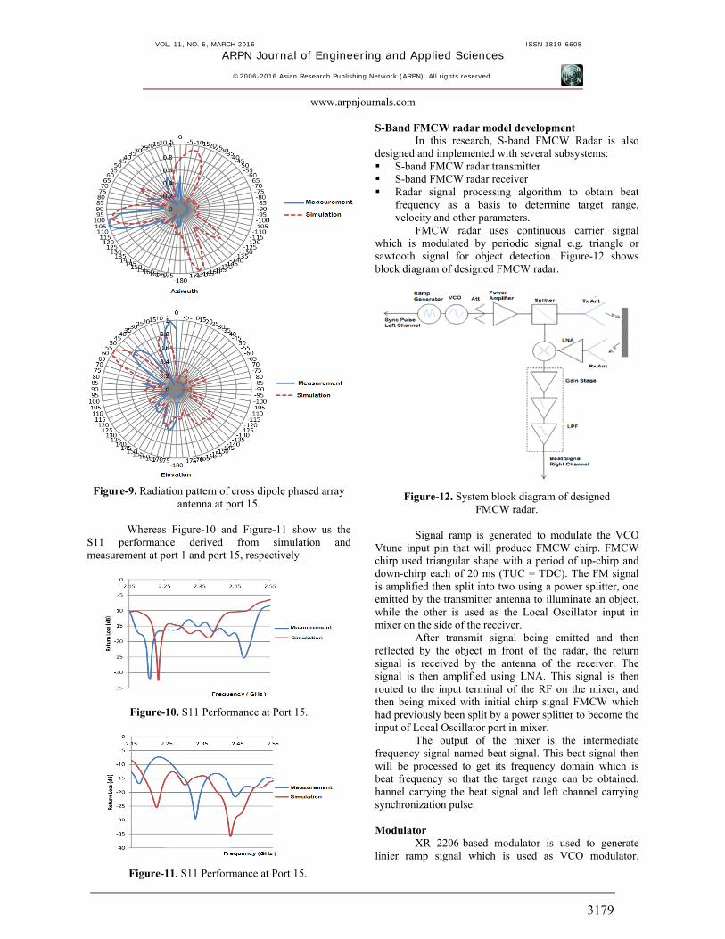
For evaluating the performance of beamforming functions, we have made some indoor measurements to ensure each port of 16 ports of proposed cross dipole array works well. The following radiation pattern profile are shown as in Figure-8 for port 1 and port 15 in azimuth and elevation plane respectively.
Figure-8. Radiation pattern of cross dipole phased array antenna at port 1.
VOL. 11, NO. 5, MARCH 2016 ISSN 1819-6608
ARPN Journal of Engineering and Applied Sciences
©2006-2016 Asian Research Publishing Network (ARPN). All rights reserved.
www.arpnjournals.com
3179
Figure-9. Radiation pattern of cross dipole phased array antenna at port 15.
Whereas Figure-10 and Figure-11 show us the
S11 performance derived from simulation and measurement at port 1 and port 15, respectively.
Figure-10. S11 Performance at Port 15.
Figure-11. S11 Performance at Port 15.
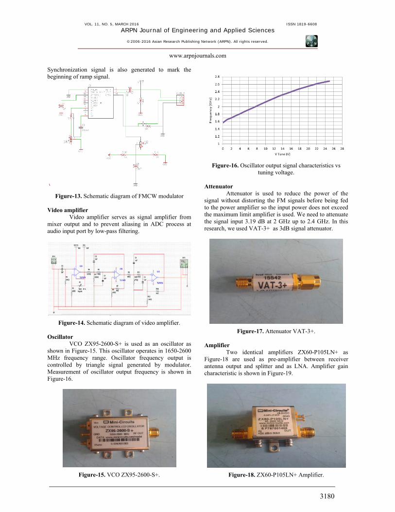
S-Band FMCW radar model development In this research, S-band FMCW Radar is also
designed and implemented with several subsystems: S-band FMCW radar transmitter S-band FMCW radar receiver Radar signal processing algorithm to obtain beat
frequency as a basis to determine target range, velocity and other parameters.
FMCW radar uses continuous carrier signal which is modulated by periodic signal e.g. triangle or sawtooth signal for object detection. Figure-12 shows block diagram of designed FMCW radar.
Figure-12. System block diagram of designed FMCW radar.
Signal ramp is generated to modulate the VCO
Vtune input pin that will produce FMCW chirp. FMCW chirp used triangular shape with a period of up-chirp and down-chirp each of 20 ms (TUC = TDC). The FM signal is amplified then split into two using a power splitter, one emitted by the transmitter antenna to illuminate an object, while the other is used as the Local Oscillator input in mixer on the side of the receiver.
After transmit signal being emitted and then reflected by the object in front of the radar, the return signal is received by the antenna of the receiver. The signal is then amplified using LNA. This signal is then routed to the input terminal of the RF on the mixer, and then being mixed with initial chirp signal FMCW which had previously been split by a power splitter to become the input of Local Oscillator port in mixer.
The output of the mixer is the intermediate frequency signal named beat signal. This beat signal then will be processed to get its frequency domain which is beat frequency so that the target range can be obtained. hannel carrying the beat signal and left channel carrying synchronization pulse. Modulator
XR 2206-based modulator is used to generate linier ramp signal which is used as VCO modulator.
VOL. 11, NO. 5, MARCH 2016 ISSN 1819-6608
ARPN Journal of Engineering and Applied Sciences
©2006-2016 Asian Research Publishing Network (ARPN). All rights reserved.
www.arpnjournals.com
3180
Synchronization signal is also generated to mark the beginning of ramp signal.
Figure-13. Schematic diagram of FMCW modulator Video amplifier
Video amplifier serves as signal amplifier from mixer output and to prevent aliasing in ADC process at audio input port by low-pass filtering.
Figure-14. Schematic diagram of video amplifier.
Oscillator VCO ZX95-2600-S+ is used as an oscillator as
shown in Figure-15. This oscillator operates in 1650-2600 MHz frequency range. Oscillator frequency output is controlled by triangle signal generated by modulator. Measurement of oscillator output frequency is shown in Figure-16.
Figure-15. VCO ZX95-2600-S+.
Figure-16. Oscillator output signal characteristics vs tuning voltage.
Attenuator
Attenuator is used to reduce the power of the signal without distorting the FM signals before being fed to the power amplifier so the input power does not exceed the maximum limit amplifier is used. We need to attenuate the signal input 3.19 dB at 2 GHz up to 2.4 GHz. In this research, we used VAT-3+ as 3dB signal attenuator.
Figure-17. Attenuator VAT-3+.
Amplifier Two identical amplifiers ZX60-P105LN+ as
Figure-18 are used as pre-amplifier between receiver antenna output and splitter and as LNA. Amplifier gain characteristic is shown in Figure-19.
Figure-18. ZX60-P105LN+ Amplifier.
VOL. 11, NO. 5, MARCH 2016 ISSN 1819-6608
ARPN Journal of Engineering and Applied Sciences
©2006-2016 Asian Research Publishing Network (ARPN). All rights reserved.
www.arpnjournals.com
3181
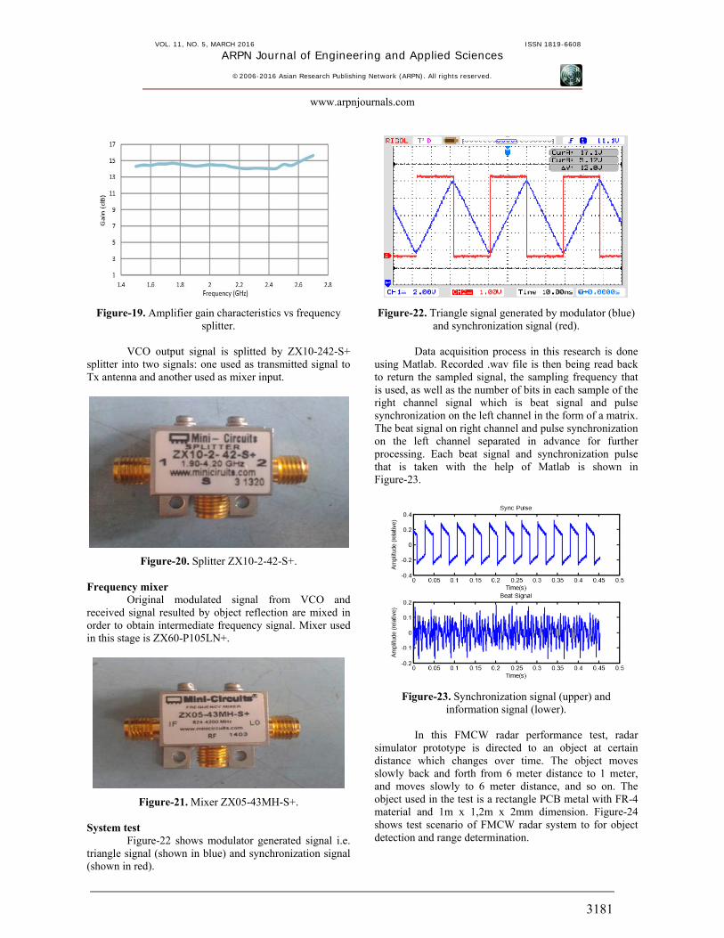
Figure-19. Amplifier gain characteristics vs frequency splitter.
VCO output signal is splitted by ZX10-242-S+
splitter into two signals: one used as transmitted signal to Tx antenna and another used as mixer input.
Figure-20. Splitter ZX10-2-42-S+. Frequency mixer
Original modulated signal from VCO and received signal resulted by object reflection are mixed in order to obtain intermediate frequency signal. Mixer used in this stage is ZX60-P105LN+.
Figure-21. Mixer ZX05-43MH-S+. System test
Figure-22 shows modulator generated signal i.e. triangle signal (shown in blue) and synchronization signal (shown in red).
Figure-22. Triangle signal generated by modulator (blue) and synchronization signal (red).
Data acquisition process in this research is done
using Matlab. Recorded .wav file is then being read back to return the sampled signal, the sampling frequency that is used, as well as the number of bits in each sample of the right channel signal which is beat signal and pulse synchronization on the left channel in the form of a matrix. The beat signal on right channel and pulse synchronization on the left channel separated in advance for further processing. Each beat signal and synchronization pulse that is taken with the help of Matlab is shown in Figure-23.
Figure-23. Synchronization signal (upper) and information signal (lower).
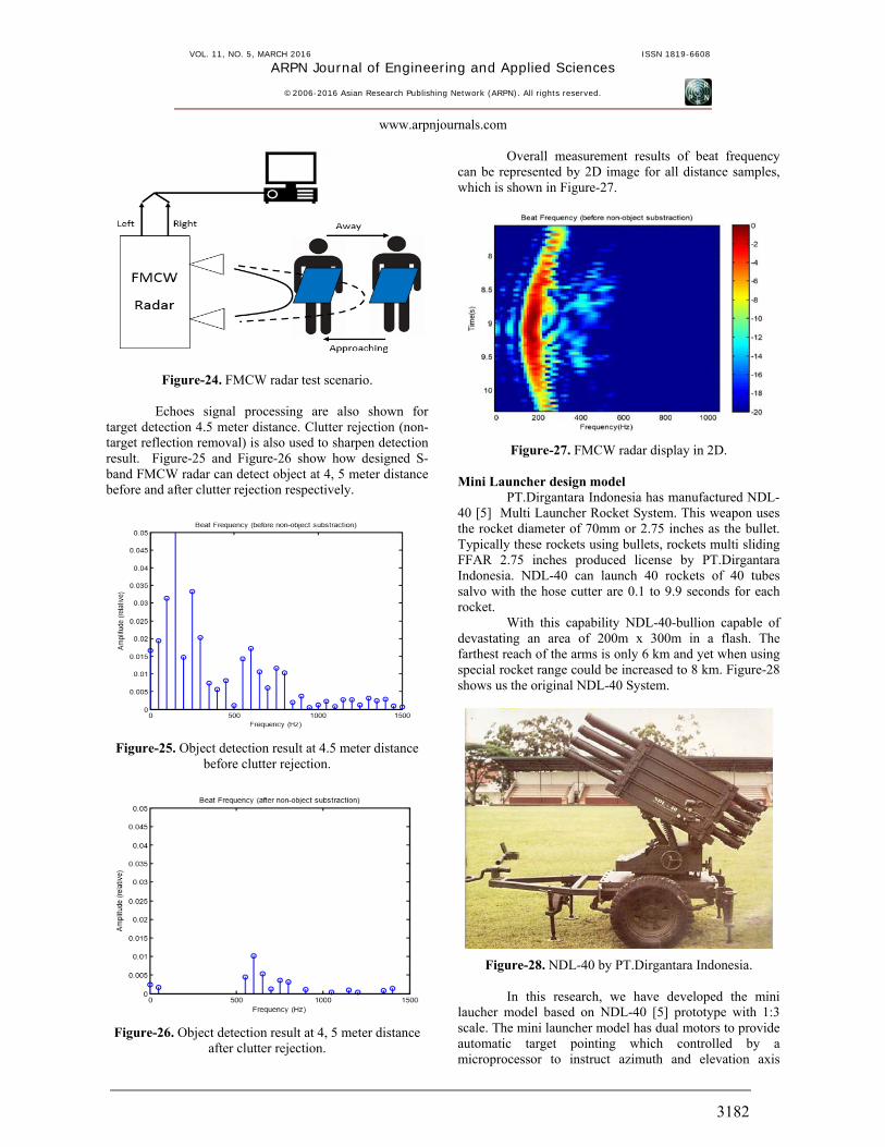
In this FMCW radar performance test, radar
simulator prototype is directed to an object at certain distance which changes over time. The object moves slowly back and forth from 6 meter distance to 1 meter, and moves slowly to 6 meter distance, and so on. The object used in the test is a rectangle PCB metal with FR-4 material and 1m x 1,2m x 2mm dimension. Figure-24 shows test scenario of FMCW radar system to for object detection and range determination.
VOL. 11, NO. 5, MARCH 2016 ISSN 1819-6608
ARPN Journal of Engineering and Applied Sciences
©2006-2016 Asian Research Publishing Network (ARPN). All rights reserved.
www.arpnjournals.com
3182
Figure-24. FMCW radar test scenario.
Echoes signal processing are also shown for target detection 4.5 meter distance. Clutter rejection (non-target reflection removal) is also used to sharpen detection result. Figure-25 and Figure-26 show how designed S-band FMCW radar can detect object at 4, 5 meter distance before and after clutter rejection respectively.
Figure-25. Object detection result at 4.5 meter distance before clutter rejection.
Figure-26. Object detection result at 4, 5 meter distance after clutter rejection.
Overall measurement results of beat frequency can be represented by 2D image for all distance samples, which is shown in Figure-27.
Figure-27. FMCW radar display in 2D. Mini Launcher design model
PT.Dirgantara Indonesia has manufactured NDL-40 [5] Multi Launcher Rocket System. This weapon uses the rocket diameter of 70mm or 2.75 inches as the bullet. Typically these rockets using bullets, rockets multi sliding FFAR 2.75 inches produced license by PT.Dirgantara Indonesia. NDL-40 can launch 40 rockets of 40 tubes salvo with the hose cutter are 0.1 to 9.9 seconds for each rocket.
With this capability NDL-40-bullion capable of devastating an area of 200m x 300m in a flash. The farthest reach of the arms is only 6 km and yet when using special rocket range could be increased to 8 km. Figure-28 shows us the original NDL-40 System.
Figure-28. NDL-40 by PT.Dirgantara Indonesia.
In this research, we have developed the mini laucher model based on NDL-40 [5] prototype with 1:3 scale. The mini launcher model has dual motors to provide automatic target pointing which controlled by a microprocessor to instruct azimuth and elevation axis
VOL. 11, NO. 5, MARCH 2016 ISSN 1819-6608
ARPN Journal of Engineering and Applied Sciences
©2006-2016 Asian Research Publishing Network (ARPN). All rights reserved.
www.arpnjournals.com
3183
motors movements according to received radar signal when radar detects target.
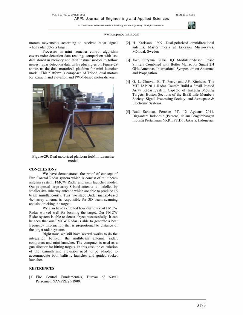
Processes in mini launcher control algorithm covers radar detection data reading, comparison with last data stored in memory and then instruct motors to follow newest radar detection data with reducing error. Figure-29 shows us the dual motorized platform for mini launcher model. This platform is composed of Tripod, dual motors for azimuth and elevation and PWM-based motor drivers.
Figure-29. Dual motorized platform forMini Launcher model.
CONCLUSIONS
We have demonstrated the proof of concept of Fire Control Radar system which is consist of multibeam antenna system, FMCW Radar and mini launcher model. Our proposed large array S-band antenna is modelled by smaller 4x4 subarray antenna which are able to produce 16 beam simultaneously. This two stage Butler matrix-based 4x4 array antenna is responsible for 3D beam scanning and also tracking the target.
We also have exhibited how our low cost FMCW Radar worked well for locating the target. Our FMCW Radar system is able to detect object successsfully. It can be seen that our FMCW Radar is able to generate a beat frequency information that is proportional to distance of the target radar systems.
Right now, we still have several works to do the integration between the multibeam antenna, radar, computers and mini launcher. The computer is used as a gun director for hitting targets. In this case the calculation of the azimuth and elevation need to be adapted to accommodate both ballistic launcher and guided rocket launcher. REFERENCES [1] Fire Control Fundamentals, Bureau of Naval
Personnel, NAVPRES 91900.
[2] H. Karlsson. 1997. Dual-polarized omnidirectional antenna. Master thesis at Ericsson Microwaves. Mölndal, Sweden
[3] Joko Suryana. 2006. IQ Modulator-based Phase
Shifters Combined with Butler Matrix for Smart 2.4 GHz Antennas, International Symposium on Antennas and Propagation.
[4] G. L. Charvat, B. T. Perry, and J.P. Kitchens. The
MIT IAP 2011 Radar Course: Build a Small Phased Array Radar System Capable of Imaging Moving Targets, Boston Sections of the IEEE Life Members Society, Signal Processing Society, and Aerospace & Electronic Systems.
[5] Budi Santoso, Peranan PT. 12 Agustus 2011.
Dirgantara Indonesia (Persero) dalam Pengembangan Industri Pertahanan NKRI, PT.DI , Jakarta, Indonesia.


![FMCW Implementation of Phase-Attached Radar …sdblunt/papers/IEEERC19-FMCW-PARC.pdf · 2019-02-22 · continuous phase frequency shift keying (CPFSK) [23]. In addition, the communication](https://img.pdfslide.us/doc/110x75/5f31a055d3a1321e870dfdc0/fmcw-implementation-of-phase-attached-radar-sdbluntpapersieeerc19-fmcw-parcpdf.jpg)