Embed Size (px)
Citation preview
• 'J!
:"n1i:..1.t J t~ ~J J i '~ 'l! :: 1 ) {
:i(':"( ;-li, ·70 .....:~ ~;m( . 1 ~ '~ r
DESIGN AND FLOW CONTROL OF SUBSURFACE 'INJECTIONSYSTEM FOR MOBILE OIL TANKS ' ,' . :
) ll
Zhang Shujing,Gu Xiujuan(Shanghai Fire Research Institut.e,60I ,Zhong Shan NanEr Road,Shanghai 200032,China)
I.INTRODUCTION
There are more than fifty oil tanks of various sizes ,i n HainanProvince,although its petrochemical industry 'i s less advanced than someotherprovinces.Among these oil tanks, Haikou Oil Tanks and 'Li n ShuiEst.at.e Oil Tanks are bot.h of a considerable scale.Evideritly it is notenough t.o just maint.ain a few fire ext.inguish,rs in the oil tanks . Whalis more,Hainanis a t.ypical heavy-t.~lnderstormarea,with long sunshineperiod and high temperature.AII ' t.hese mean very great. fire hazards.Inview of such condit.ion~ t.he fluoroprotein foam subsurface injection fireextinguishing system is adopted by Mobil Oil Tanks in Hainan Province.InChina t.he design of such a syst.em is yet. a " co·mpri.,rat.ively " ne wt.echi'alque,which involves a number of t crucial :' problems not. tullysolved.ln t.his paper,the writers explore preliminarili t.he design andflow control of this systeln as used in the l'fire protection engineeringof Mobil Oil Tanks in.Hainan.
Usually,in order to det.ermine the flow of t.he foam solution in such asyst~m,the d~signer takes the nominal flow value of the foam generatoras the basis of his calculation and takes it as a fixed value.He wouldconsider that the foam generated is only related to the foamexpa~sion,as is also so stated in the instruction book of the high backpressure foam generator.A back pressure cont.rol valve is therefore fixedto t.he outlet of the foam generator to compenste for the effects of thechange of the liquid level' in the oil tank (i.e .• the change in thest.aUc pressure of oil in the tank),so that the quantity of the flowgene~ated and the speed at which the foam flows into the oil may beregulated.But it has to be pointed out that the key to controlling theflow of the system does not lie in regulating the back pressure of thefoam generat.or.Regulating the back pressure often brings about changesin all the working parameters.Therefore.in order to control the flow ofthe system.there should be a comprehensive cont.rol of all the mainworking parameters of the system.These include parameters of the pumpoutlet pressure,the foam generate inlet pressure. foam solutionconcentration,foam solution supply intensity,quantity of foamgenerated.speed of foam flowing into the oil,speed of extinguishment ofthe fire,etc .The usual method a designer uses consists of'the following:(a) Ascertain the maximum area to be protected by the system.(b) Calculate the quantity of foam required for the prot.ectionof theare::t .(c) Choose the Lype of high back pressure foam generator.basing on therequired quantity of the foam and the flowing speed off!lhe foam solution(d) Choose the type of proportioner and fire pump.basing on the quantityof the foam solut.ion.
-348-
Copyright © International Association for Fire Safety Science
(e) Calculate the quantity of foam liquid a c t ua l l y requ ired.In selecting the right type of equipment, it is often nigh imposs ibleto find a piece of equipment whos e nominal value corresponds with thedesign parameters.It often happens that "One is not enough and two aretoo many ."The usual approach to this problem . is let there be asurplus.which means an excessive safety coefficient and a wa~te .Yet thedesigners of the subsurface in jection system for Mobil Oil Tanks haverealized the comprehensive control of the working parameters with due 'consideration 'f o r safety as well as economy . .
2.THE METHOD FOR BASICALLY CONTROLLING TilE WORKINGPARAtIETERS OF THE SUBSURFACE INJECTION FIREEXTINGUISHING SYSTEM
As is cha~acteristic of the petrochemical industry,in . t h e Mobil Oi lTanks subsurface injection system there are pipes and valves of manytypes and specifications,beside the fire pumps,the proportion~rs and thehigh back pressure foam generators. It is easily understandable that afunc £ional relation exists among the parameters of the outl~t pressureof the fire 'pump,the flow of the foam solution,the density of the foamsolution, the resistance of the pipe to the foam soluti dn,the inletpressure of the foam generat.or,the quantity of the foam generated,theresistance of the pipe to the foam,the speed of the foam flowing intothe . oil,the speed of fire extinguishment and other workingparameters.This means the designer may effect a comprehensive control ofthe working parameters by choosing the suitable types-o~equipment andregulating the valves.(1) High Back Pressure Foam Generator:This is the key ~quipmen~ of the subsurface injection fire extinguishingsystem:While designing the system people often ' take the nominal flow ofthe high back pressure foam generator as a .f i x ed one.Actually the flowis not unchangeable,because a change in either the inlet pressure or theback pressure of the foam generato~ can cause ,a chcinge in the flow.Bu~ ,
the difference between the effects caused by the inlet pressure and theback pressure is quite big.(2) Regulation of The Back Pressure of The Foam Generator:It is clearly stated in the instruction book of the foam generator thatwithin the limitation of the nominal flow,the flow of the system may beregulated through regulating the back pressure regulating valves.Suchregulation however,is in our opinion of little importance,since .i t isvery limited.The reasons of the limitation are: .(a) Mainly,the regulation of the back pressure, is to compensate thechanges in the static pressure of the oil.The magnitude and range of t.h~/change of the bech pressure are approximate to that of , the staticpressure of the oil contained in the tank,always within the range of 00.15 MPa. '.(h) In this system.the foam solution, becomes foam after passing ~hroug~
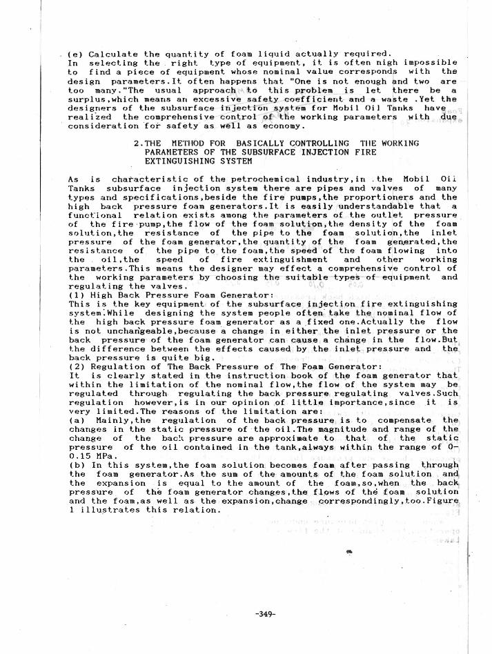
the foam generator.As the sum of the amounts of the foam solution . andthe expansion is equal to the amount of the foam,so.when the bac~pressure of th~ foam generator changes.the flows of th~ foam solutionand the foam.as well as t he expansion,change porrespondingly,too.FigureI illu~trates this relation .
I- ~ . - ...
-349-
........ ................ ""... ,,,
"\ \ \\ \'
\ \ \\ \ \
\ \ \\ \ \\ \ \
\ \ \\ \ \\ \ \\ , II \ II I I
I
0.200."0./0
I/
,.0o
2.,
2.0
Fig .l :PCY 900 high back pressure foam generator-curves showing relation between expansion andoutlet back pressure
I FoamIexpansion 1.0
Within the limited'range of the back pressure regulation.the changein foam expansion is insignificant and it is quite unnecessary toregulate the back pressure of the foam generator.(3) Regulation of The Inlet Pressure of The Foam Generator:The subsurface injection system require~ a. sufficient supply of foamsolution in quantity ahd in speed.At the same time it requires that theflow of the foam into the oil tank be of limited speed.Since the tworequirements hold each other in check.the change in the flow of the foamsolution has to be limited to a very small scope to effect only atargeted control.Otherwise the following conditions will appear:(a) A big change in the magnitude and .peed of the flow will cause achange in the concentration of the foam solution,affecting the foamquality and the efficiency of fire extinguishing.(b) A big change in the magnitude and speed of the flow will causepressure change and pressure loss in the pipes.Especially,when the flowincrease is too big,a reverse-flow back pressure may be reached;makingthe (oam generalor unable to absorb air and produce foam,thus losing itsfire extinguishing power.
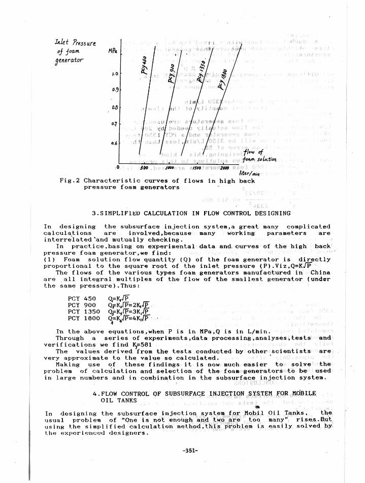
The regulation of the inlet pressure of the foam generator has agreat effect on the working parameters of the whole syst~m,as shown inFig 2.
'''hen the, LnLe L ' pr-e s s ur-e undergoes a change of 0.4 MPa during normaloperation,the change of the flow will be more than 30%,which must not betaken 1 ightly.
-350-
kle t 'tress ureoj joam. ~IPll
gen.erat or
,,0
0,6
,0,
I ,
PCY 450PCY 900PCY 1350PCY 1800
liter/l1Ii"Fig.2 Characteristic curves of flows in high back
pressure foam generators
3.SHIPLIFlt:;U CALCULATION IN FLOW CONTROL DESIGNING
I n designing the subsurface injection system,a great many complicatedcalculations are i nvo l v e d , be c a u s e many working parameters areinterre'lated 'and ,mutually checking.
In practice.basing on experimental data and curves of ~he high backpressure foam generator ,we find: <'(1) Foam solution flow quantity (Q) of the foam generator is directlyproportional t o the square root of the inlet. pressure (P).Viz,Q=KJp:~
The flows of the var ious types foam generat.ors manufactured in Chinaare , a l l integral multiples of the flow of the smallest generat.or (underthe same pressure).Thus:
Q,=K,IPQr=Kip=2K,JP , 'Q:fKJI'P=3KJPQ=K!P=4K.lP,
:+ '+
In the above equat.ions,when P is in MPa,Q is in L/min.Through a series of experiments,data processing,analyses,tests and
verifications we find ~=581
The values derived from the tests conducted by other scientists arevery approximate to the value so calculated. .
Making use of these findings it is now much easier to solve theproblem of 'calc~lation and selection of the foam generators to be usedin large numbers and in combination in the subsurface injection system ., l ,)
4.FLOW CONTROL OF SUBSURFASE INJECTI~N SYSTEM fOR ~MdB I L~OIL TANKS
In designing the subsurface injection system for Mobil Oil Tanks • . th>~:usual problem of "On~ is not enough ~nd two a~e too many" rise•. But.using the simplified calculation method :th's prcihlem is easily solv~d b~t.he e xpe r' i e ll,;ed d e s i gll'~rs .
-351-
Example:A 5000 T oil tank with a 'f i xed top has a diameter of 23 m.Clwose the
type of high back pressure foam generator and determille the inletpressure .
]l. D2
Oil tank cross section area A= =415 sq.m,4
Foam solution flow Q=Aq=3320 L/minThis is the practical quantity of the flow needed determined through
calculation. .If twoPCY 1800 foam generators are used,the flow will be 3600
L/min.more than the flow actually needed by 280 L/min .with an error of8%.If a PCY 1800 foam generator and a PCY 1350 foam generator are usedtogether,the flow will be 3150 L/min,less than the flow actually neededby 170 L/min,with an error of 5%.
In practical designing,this kind of contradiction is .unavoidable.There are two solutions to this problem:(a) If two PCY 1800 foam generators are used,the inlet pressure shouldbe suitably lowered:
Q=KJPQJ 2
(3320/2)P= = -------- =0.510 MPa
This will be th~ inlet pressure iri the case of two PCY 1800 foamgenerators being used.(b) If one PCY 1800 foam generator and onePCY 1350 foam generator areused together,the inlet pressure shouldb~ suitably raised:
Q=K[PQJ
P=-- =K'
3320 '= 0.666 MPa· . ,
-,
This is the inlet pressure in the case of one PCY 1800 and ~ne PCY1350 foam generators being used together.
On the basis of the above calculations,it can be seen that. theoretically ,either method is feasible,with the inlet pressuresr"~Rlll.r-jted respectively at 0.510 MP,'land 0.666 MP:l .Jn bot.h r.l'.IIH!:'> tho flow
' lI fH~dml Idll he avr..lilrible.However,inprrictice it I:,> nf!cr!:'>S::lr'Y 1.0 considerfully the characteristics of the pumps and the foam generators.thepressure loss in the foam generators,and the diameters and lengths ' o fthe pipes.Only after comprehensive consideration and balancing theadvantages and di sadvantages can a right choice be made' from the two
I solutions.That choice can ensure safety as well as economy .
5 .CO~CLUS IONS
(1) For the subsurface injection system for Mobil Oil Tanks not just thedesigning,but the tests and verifications of the syst e.are of crucialimportance.(2) In designing the system,to make ~re c i s e calculations of the workingparameters,to carry out comprehensive analyses, and to c hoos e the righttype of equipment are a complicated and diff.icuit process.But the
-352-
correct and appropriate installation of all the equipment.andparticularly the tests and verifications of the working of the systemafter installation,are ultimately important for the realization of thedesign.This part of the engineering can be still more difficult and ruuitbe done carefully.(3) The working experience . proves that the new technique for thesubsurface injection fire extinguishing system for Mobil Oil Tanks inHainan Province is rational and sound,meeting both demands for safetyand economy.
~ -.
-r' .. '
-353-


![Nutrient removal in tropical subsurface flow constructed wetlands [Read-Only] [Compatibility Mode]](https://img.pdfslide.us/doc/110x75/588b075f1a28abdf3b8b514f/nutrient-removal-in-tropical-subsurface-flow-constructed-wetlands-read-only.jpg)