Embed Size (px)
Citation preview
International Journal on Recent Technologies in Mechanical and Automobile Engineering (IJRMAE) ISSN: 2349-7947 Volume: 2 Issue: 6 001 – 010
_______________________________________________________________________________________________
1 IJRMEE | June 2015, Available @http://www.ijrmee.org
_______________________________________________________________________________________
Design and Fabrication of Onion Seed Sowing Machine
Nilesh N. Jadhav Lecturer
Department of E & TC
AIETP, Ashoknagar, Shrirampur
Harshal R. Aher Lecturer
Dept. Of Mech. Engg.
AIETP, Shrirampur
Amol P. Ghode Lecturer
Department of Mechanical Engineering
AIETP, Ashoknagar,Shrirampur
Abstract—Today’s era is marching towards the rapid growth of agricultural as well as industrial sector. To achieve the goal of the future food demands, the farmers have to implement the new techniques which will increase the overall crop production rate. This Paper deals with the
various sowing methods used for onion seed sowing in India for seed and fertilizer placement. The comparison between the traditional sowing
method and the new proposed machine which can perform a number of simultaneous operations and has number of advantages. The main focus
behind this machine is to reduce the human effort as well as problem of availability of labor & there cost of work. Generally this machine reduces the cost of labor, efforts and total and fertilizer placement. The seed sewing machine is a key component of agriculture field. The
performance of seed sowing device has a remarkable influence on the cost and yield of agriculture products. Presently there are many
approaches to detect the Performance of seed-sowing device. The depth of seed sowing is affect the crop yield therefore to adjust the depth of
seed sowing & head to head distance between two seed a seed metering device is the heart of seed sowing machine between seed varieties. High Precision planters have been developed for many varieties of crops, for a wide Range of seed sizes, resulting to uniform seeds distribution along
the travel path, in seed Spacing. This technique result in improvement in yield: by proper operation in the field we are increase the productivity
of seed through 5% to 10%.Plant to plant distance: We are maintaining the plant to plant distance by providing a 12 number of cells on rotor.
Saving labor cost: The transplantation of onion require lot of labor as well as charge is more so we are by using this machine able to reduce the labor cost.
Keywords- Onion, Sowing, Transplantation, seed.
__________________________________________________*****_________________________________________________
I. INTRODUCTION
In developing countries like India mechanization of
agriculture was started on the use of improved hand tools and
bullock drawn improvements. Farm mechanization aims at
higher production rate reduction in human drudgery. India’s
achievements have been increasing tremendously, but not in
mechanization. One of the barriers achieving complete
mechanization is the land holdings and its fragmentation. Due
to small land holding is not possible to mechanize all the
farming operations. Large machines cannot be operated these
small farms. Also our farmers cannot afford to buy large costly
machines.
Seed sowing machine is a device which helps in the
sowing of seeds in a desired position hence assisting the
farmers in saving time and money. The basic objective of
sowing operation is to put the seed in rows at desired depth
and seed to seed spacing, cover the seeds with soil and provide
proper compaction over the seed. The paper discusses different
aspects of seed wing machine which will be helpful for the
agriculture industry to Move towards mechanization. The
agricultural industry has always been the backbone of India’s
sustained growth. As the population of India continues to
grow, the demand for Produce grows as well. Hence, there is a
greater need for multiple cropping on the farms and this in turn
requires efficient and high-capacity machines. Mechanization
of the Agricultural Industry in India is still in a stage of
infancy due to the lack of knowledge and the unavailability of
advanced tools and machinery. In traditional methods seed
sowing is done by broadcasting manually, opening furrows by
a plough and dropping seeds by hand.
Agriculture has been the backbone of the Indian
economy and it will continue to remain so for a long time. It
has to support Almost 17 percent of world population from 2.3
percent of world geographical area and 4.2 percent of world’s
water resources. The Present cropping intensity of 137 percent
has registered an increase of only 26 Percent since 1950-51.
The net sown area is 142 MHz the basic objective of sowing
operation is to put the seed and fertilizer in rows at desired
depth and spacing, cover the seeds with soil and provide
proper compaction over the seed. The recommended row to
row spacing, seed rate, seed to seed Spacing and depth of seed
placement vary From crop to crop and for different
Agricultural and climatic conditions to achieve optimum
yields and an efficient Sewing machine should attempt to
fulfill these requirements. In addition, saving in Cost of
operation time, labor and energy are other advantages to be
derived from use of improved machinery for such operations.
A traditional method of seed sowing has many disadvantages.
This paper is about the different types of methods of seed
sowing and fertilizer placement in the soil and developing a
multifunctional seed sewing machine which can perform
simultaneous operations. [1&2]
1.2 TYPES OF SOWING
The following are the three different types of seed
sowing:-
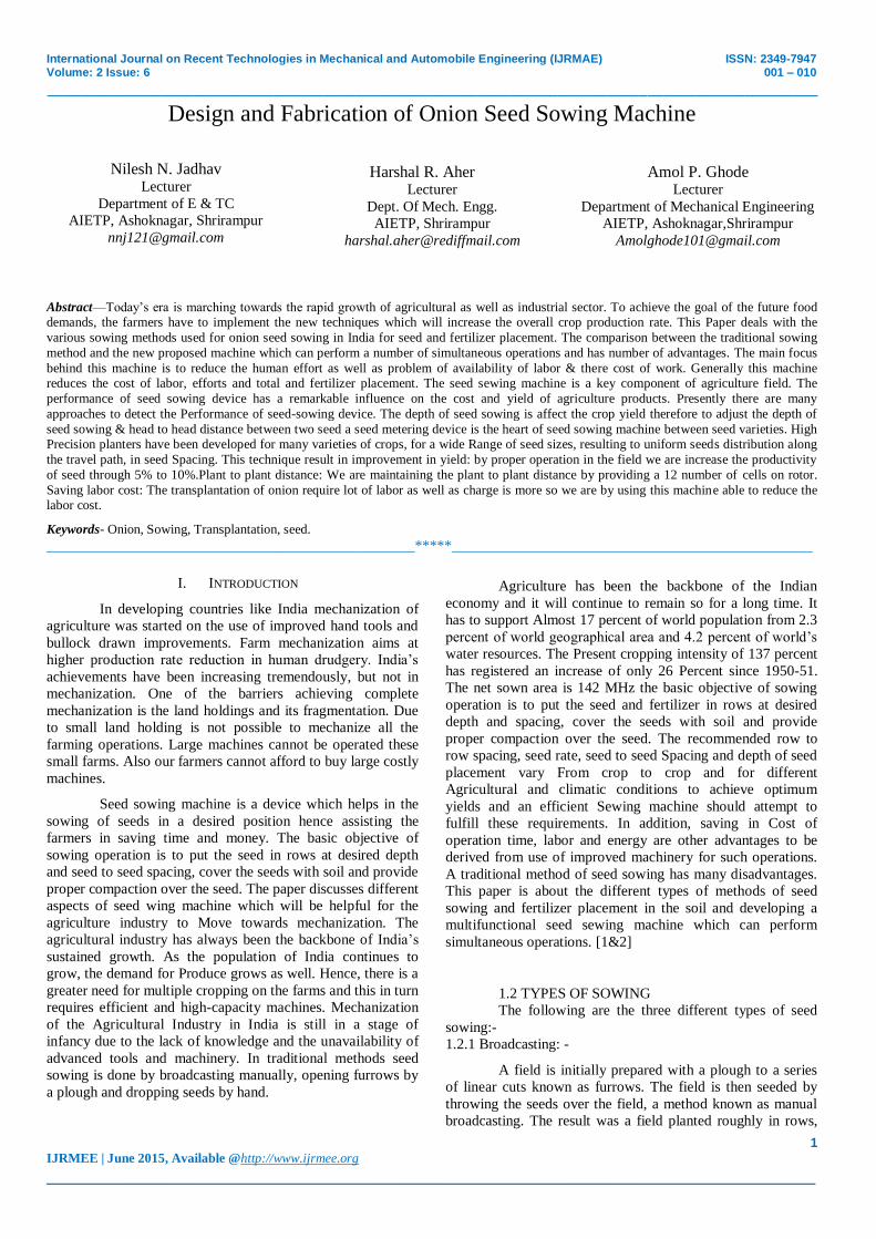
1.2.1 Broadcasting: -
A field is initially prepared with a plough to a series
of linear cuts known as furrows. The field is then seeded by
throwing the seeds over the field, a method known as manual
broadcasting. The result was a field planted roughly in rows,
International Journal on Recent Technologies in Mechanical and Automobile Engineering (IJRMAE) ISSN: 2349-7947 Volume: 2 Issue: 6 001 – 010
_______________________________________________________________________________________________
2 IJRMEE | June 2015, Available @http://www.ijrmee.org
_______________________________________________________________________________________
but having a large number of plants. When the seeds are
scattered randomly with the help of hand on the soil, the
method is called broadcasting.[2]
Figure no.1.1: Broadcasting
1.2.2 Dribbling: -
Drill sowing and dribbling (making small holes in the
ground for seeds) are better method of sowing the seeds. Once
the seeds are put in the holes, they are then covered with the
soil. This saves time and labor and prevents the damage of
seeds by birds.
3. Another method of sowing the seeds is with the
help of a simple device consisting of bamboo tube with a
funnel on it attached to a plough. As the plough moves over
the field the tube attached to it leaves the seeds kept in the
funnel at proper spacing and depth. The plough keeps making
furrows in the soil in which the seeds are dropped by the seed
drill. The above sowing methods have the some disadvantages
Which are as follows:-
a) No control over the depth of seed placement.
b) No uniformity in the distribution of seed placement.
c) Loss of seeds.
d) No proper germination of seeds
e) More labor requirement
f) Time required for sowing is more.
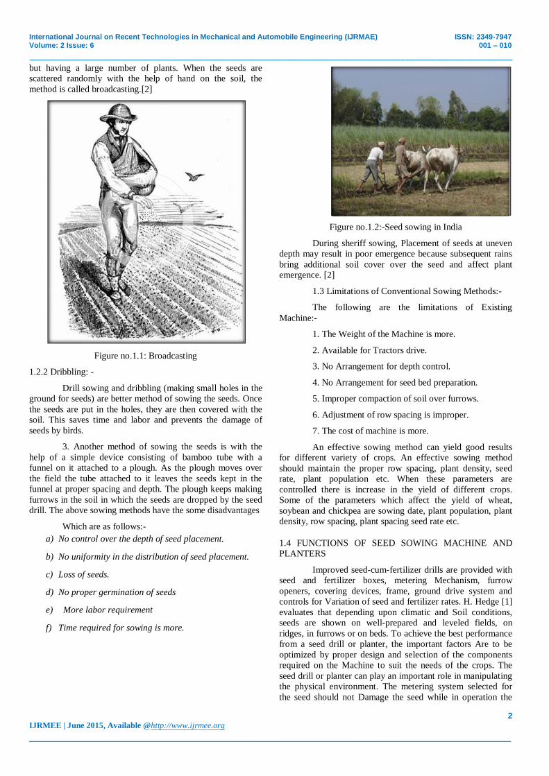
Figure no.1.2:-Seed sowing in India
During sheriff sowing, Placement of seeds at uneven
depth may result in poor emergence because subsequent rains
bring additional soil cover over the seed and affect plant
emergence. [2]
1.3 Limitations of Conventional Sowing Methods:-
The following are the limitations of Existing
Machine:-
1. The Weight of the Machine is more.
2. Available for Tractors drive.
3. No Arrangement for depth control.
4. No Arrangement for seed bed preparation.
5. Improper compaction of soil over furrows.
6. Adjustment of row spacing is improper.
7. The cost of machine is more.
An effective sowing method can yield good results
for different variety of crops. An effective sowing method
should maintain the proper row spacing, plant density, seed
rate, plant population etc. When these parameters are
controlled there is increase in the yield of different crops.
Some of the parameters which affect the yield of wheat,
soybean and chickpea are sowing date, plant population, plant
density, row spacing, plant spacing seed rate etc.
1.4 FUNCTIONS OF SEED SOWING MACHINE AND
PLANTERS
Improved seed-cum-fertilizer drills are provided with
seed and fertilizer boxes, metering Mechanism, furrow
openers, covering devices, frame, ground drive system and
controls for Variation of seed and fertilizer rates. H. Hedge [1]
evaluates that depending upon climatic and Soil conditions,
seeds are shown on well-prepared and leveled fields, on
ridges, in furrows or on beds. To achieve the best performance
from a seed drill or planter, the important factors Are to be
optimized by proper design and selection of the components
required on the Machine to suit the needs of the crops. The
seed drill or planter can play an important role in manipulating
the physical environment. The metering system selected for
the seed should not Damage the seed while in operation the

International Journal on Recent Technologies in Mechanical and Automobile Engineering (IJRMAE) ISSN: 2349-7947 Volume: 2 Issue: 6 001 – 010
_______________________________________________________________________________________________
3 IJRMEE | June 2015, Available @http://www.ijrmee.org
_______________________________________________________________________________________
functions of a well-designed seed drill or planter are as
follows:
Meter seeds of different sizes and shape, Place the
seed in the acceptable pattern of distribution in the field, Place
the seed accurately and uniformly at the desired depth in the
soilandCover the seed and compact the soil around it to
enhance germination and emergence. [2&3]
II. FUNCTIONAL COMPONENT OF MACHINE
By eliminating limitation of component of conventional seed
sowing machine we design new component and provide
special arrangement for sowing of small seed such as onion
seed. There are eleven functional components of seed sowing
machine.
Sara Machine
Ground Wheel
Furrow Opener
Sweep
Seed Rotor Shaft
Ground Wheel Shaft And Intermediate Shaft
Chain And Sprocket Arrangement
Seed Tube
Seed Covering Unit
Seed Box
Seed Rotor
3.1 SARA MACHINE:
The main frame consist of hitch unit which is use to
connect a machine to tractor. Hitch unit consist of three point
linkage hitch attachment. It consists of MS strips of 50×5 mm
in size. Upper end of hitch is 55 apart from each other and
form attachment for top link of tractor. The lower end is
welded 320 mm apart on main frame. Two supporting MS
flats are attached at the upper end to give the support and
welded at rear end of main frame. Two 370 mm MS flat 50×5
mm are welded below main frame to from a support for the
lower linkage attachment. Sara machine is shown in figure 3.1
Figure no.:-3 1 Main Frame (Sara machine)
3.2 GROUND WHEEL:
The ground wheel provided at the center of the frame
from the functional component of power transmission unit.
The diameter of the ground wheel is 280 mm. The 12 number
of 20*4 mm strips are attached at the inner periphery of
ground wheel to the hub by welding. The ground wheel rotates
along with the shaft on which they are mounted. The lugs
provided at the peripheral end help to develop better grip on
the soil. The rotation of ground wheel causes the rotation of
seed rotors in the seed box through chain and sprocket
arrangement. The ground wheel is shown in figure 3.2
Figure no:-3.2 Ground Wheel
3.3 SEED FURROW OPENER:
There are 13 furrow openers for seed fitted on the
channel frame of the planter as the desired placing. Each
furrow opener is fitted with sweep. The distance between two
furrows is 150mm. The furrow is made from M.S. strip of
dimensions 40×10 mm.
Furrow opener is shown in figure 3.3
Figure no.:-3.3. Furrow Opener.
3.4 SWEEP:

International Journal on Recent Technologies in Mechanical and Automobile Engineering (IJRMAE) ISSN: 2349-7947 Volume: 2 Issue: 6 001 – 010
_______________________________________________________________________________________________
4 IJRMEE | June 2015, Available @http://www.ijrmee.org
_______________________________________________________________________________________
There are 13 number of sweeps are fitted on the seed
furrow opener with the help of M.S. strip whose one end is
attach to the furrow by using M6 nut bolts as well as another
end attach by welding. The inclination is provide for sweep for
proper penetration in the soil. The space is provide between
the seed furrow opener and sweep for insertion of seed tube.
The sweep is shown in figure.3.4
Figure no: 3.4 Sweep
3.5 SEED ROTOR SHAFT
The power transmission shaft fitted to the seed box,
rotate inside the bush provided at the end of each seed box.
The shaft consists of MS bar of 20 mm diameter and 1260 mm
length. Both end of shaft of diameter is 15 mm up to 2mm
respectively after that provides a 2 mm slot on shaft both side
up to 36 mm for positive engagement of seed rotors. At the
centre of shaft sprocket is fixed. the seed rotor shaft is shown
in figure 3.5
Figure no.3.5 Seed Rotor shaft
3.6 GROUND WHEEL SHAFT AND INTERMEDIATE
SHAFT
Ground wheel and sprocket are rigidly mounted on
ground wheel shaft. An intermediate shaft supports two
sprockets. One sprocket is connected to the ground wheel shaft
sprocket through chain and second sprocket is connected to the
seed rotor shaft through chain.\
Figure no.3.6. Ground Wheel Shaft and Intermediate shaft
3.7 CHAIN AND SPROCKET ARRANGEMENT
The power to the shaft of the seed metering
mechanism is transmitted by means of roller chain and
sprocket arrangement. The power to the intermediate shaft
provided at center is transmitted from ground wheel shaft;
power from intermediate shaft is transmitted to the seed rotor
shaft. The four sprockets of 70 mm diameter and having 13
teeth are used to transmit power to the shaft. Two sprockets
are mounted on intermediate shaft, one sprocket on ground
wheel shaft and one on seed rotor shaft. The chain and
sprocket arrangement is shown in figure. 3.7

International Journal on Recent Technologies in Mechanical and Automobile Engineering (IJRMAE) ISSN: 2349-7947 Volume: 2 Issue: 6 001 – 010
_______________________________________________________________________________________________
5 IJRMEE | June 2015, Available @http://www.ijrmee.org
_______________________________________________________________________________________
Figure no.3.7 Chain and Sprocket arrangement
3.8 SEED TUBES
13 number of plastic tubes each having length750
mm and each having diameter 12mm. there are 7 seed tubes
are provided in first seed box and another six are attach to the
second seed box. One end is fixed to the funnel and another
end is provided in between sweep and furrow opener in order
to drain the seeds in the furrows.
3.9 SEED COVERING DEVICE
The device is used to retain sufficient loose soil over
a dropped seed to prevent moisture less and avoid a crust
formation. The strip of MS flat of size 20*4 mm and 1700 mm
long is used as a seed covering device. The strip is attached
with a nut and bolts arrangement to the extended arms of the
frame. The depth of the seed covering device is adjustable.
The seed covering device is shown in figure.3.8
Figure no.:3.9 Seed covering device
3.10 SEED BOX
It is made up of 4mm thick plastic sheet. There are
two seed box are provided in each box contain 7 rotor. The
each seed box capacity is 1.5 kg of onion seed. The overall
length and width of seed box 360 mm and 270 mm
respectively. The box is mounted on secondary frame with the
help of support. In secondary portion of the seed box a level of
seed is maintained by adjusting the screws provided at upper
side. The seed box is shown in figure.3.10
Figure no.:-3.10 Seed Box
3.11 SEED ROTORS
There are seven number of seed rotor are provided in
each seed box. The outer diameter of seed rotor is 100 mm and
thickness is 4 mm. There are 12number of seed cells are
provided at periphery of each seed rotor. A elliptical hole is
provided at the center of seed rotor. Elliptical shape of the hole
provides positive engagement of the shaft. The seed rotor is
shown in figure.3.11
Fig no:-3.11 Seed Rotor
III WORKING OF MACHINE
4.1 WORKING OF SEED SOWING MACHINE:
When the implement attaché to the tractor and
operated in the field. A tractor is drawn in forward direction
ridges are formed on either side of Sara machine at spacing of
6 feet. The space between two ridges is can be made perfectly
horizontal by adjusting top link of hitch unit attached to the
tractor.
When tractor moves in forward direction the ground
wheel in contact with the soil rotate. The lugs provided on the
outer periphery of ground wheel provide a better gripping to
the ground wheel due to which ground wheel rotate according
to the grip provided. The ground rotation of ground wheel
shaft is also rotate along with sprocket rotate. The rotary
motion of the ground wheel is transmitted to the intermediate
International Journal on Recent Technologies in Mechanical and Automobile Engineering (IJRMAE) ISSN: 2349-7947 Volume: 2 Issue: 6 001 – 010
_______________________________________________________________________________________________
6 IJRMEE | June 2015, Available @http://www.ijrmee.org
_______________________________________________________________________________________
shaft by using a chain mechanism. The intermediate shaft is
provided to reduce the vibration and fluctuation. The power or
motion from the intermediate shaft is transmitted to the
sprocket mounted on the seed rotor shaft. When sprocket on
the seed rotor shaft is rotate along with shaft also rotate.
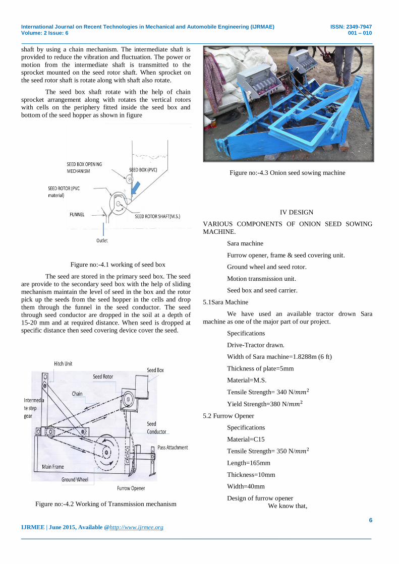
The seed box shaft rotate with the help of chain
sprocket arrangement along with rotates the vertical rotors
with cells on the periphery fitted inside the seed box and
bottom of the seed hopper as shown in figure
Figure no:-4.1 working of seed box
The seed are stored in the primary seed box. The seed
are provide to the secondary seed box with the help of sliding
mechanism maintain the level of seed in the box and the rotor
pick up the seeds from the seed hopper in the cells and drop
them through the funnel in the seed conductor. The seed
through seed conductor are dropped in the soil at a depth of
15-20 mm and at required distance. When seed is dropped at
specific distance then seed covering device cover the seed.
Figure no:-4.2 Working of Transmission mechanism
Figure no:-4.3 Onion seed sowing machine
IV DESIGN
VARIOUS COMPONENTS OF ONION SEED SOWING
MACHINE.
Sara machine
Furrow opener, frame & seed covering unit.
Ground wheel and seed rotor.
Motion transmission unit.
Seed box and seed carrier.
5.1Sara Machine
We have used an available tractor drown Sara
machine as one of the major part of our project.
Specifications
Drive-Tractor drawn.
Width of Sara machine=1.8288m (6 ft)
Thickness of plate=5mm
Material=M.S.
Tensile Strength= 340 N/𝑚𝑚2
Yield Strength=380 N/𝑚𝑚2
5.2 Furrow Opener
Specifications
Material=C15
Tensile Strength= 350 N/𝑚𝑚2
Length=165mm
Thickness=10mm
Width=40mm
Design of furrow opener
We know that,
International Journal on Recent Technologies in Mechanical and Automobile Engineering (IJRMAE) ISSN: 2349-7947 Volume: 2 Issue: 6 001 – 010
_______________________________________________________________________________________________
7 IJRMEE | June 2015, Available @http://www.ijrmee.org
_______________________________________________________________________________________
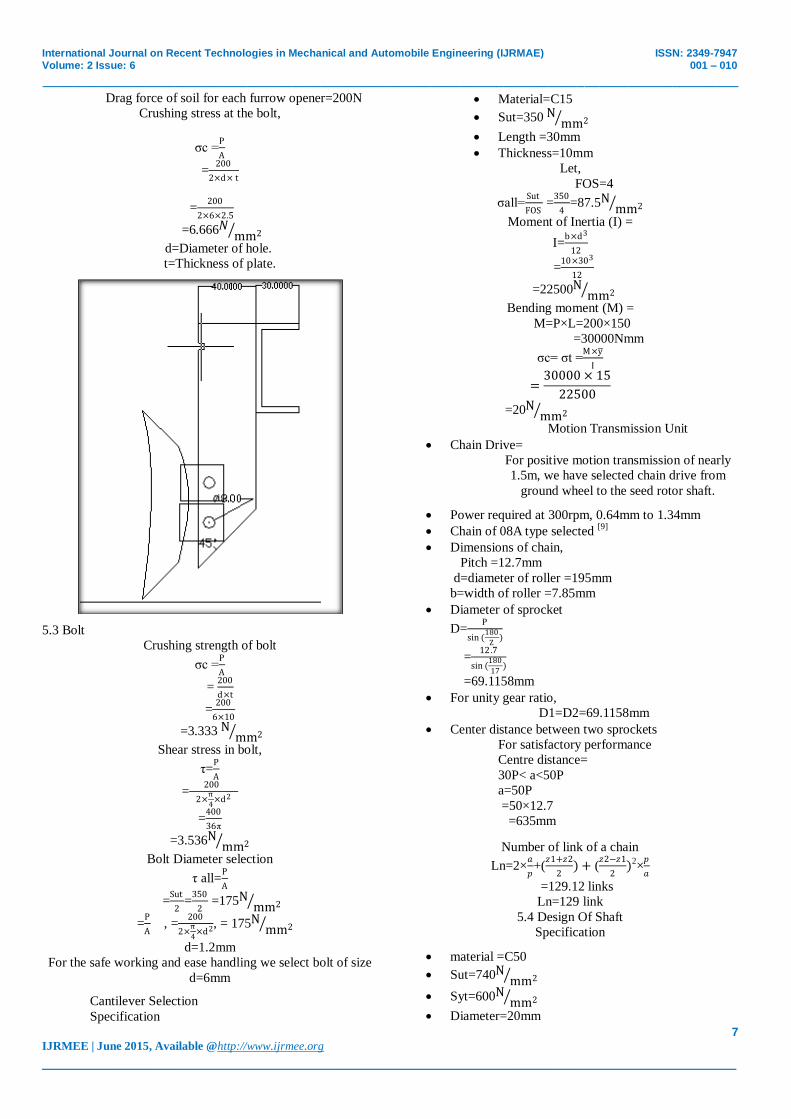
Drag force of soil for each furrow opener=200N
Crushing stress at the bolt,
σc =P
A
=200
2×d× t
=200
2×6×2.5
=6.666𝑁 mm2
d=Diameter of hole.
t=Thickness of plate.
5.3 Bolt
Crushing strength of bolt
σc =P
A
= 200
d×t
=200
6×10
=3.333 N mm2
Shear stress in bolt,
τ=P
A
= 200
2×π
4×d2
=400
36π
=3.536Nmm2
Bolt Diameter selection
τ all=P
A
=Sut
2=
350
2 =175N
mm2
=P
A , =
200
2×π
4×d2, = 175N
mm2
d=1.2mm
For the safe working and ease handling we select bolt of size
d=6mm
Cantilever Selection
Specification
Material=C15
Sut=350 N mm2
Length =30mm
Thickness=10mm
Let,
FOS=4
σall=Sut
FOS =
350
4=87.5N
mm2
Moment of Inertia (I) =
I=b×d3
12
=10×303
12
=22500Nmm2
Bending moment (M) =
M=P×L=200×150
=30000Nmm
σc= σt =M×y
I
=30000 × 15
22500
=20Nmm2
Motion Transmission Unit
Chain Drive=
For positive motion transmission of nearly
1.5m, we have selected chain drive from
ground wheel to the seed rotor shaft.
Power required at 300rpm, 0.64mm to 1.34mm
Chain of 08A type selected [9]
Dimensions of chain,
Pitch =12.7mm
d=diameter of roller =195mm
b=width of roller =7.85mm
Diameter of sprocket
D=P
sin (180
Z)
=12.7
sin (180
17)
=69.1158mm
For unity gear ratio,
D1=D2=69.1158mm
Center distance between two sprockets
For satisfactory performance
Centre distance=
30P< a<50P
a=50P
=50×12.7
=635mm
Number of link of a chain
Ln=2×𝑎
𝑝+(
𝑧1+𝑧2
2) + (
𝑧2−𝑧1
2)2
×𝑝
𝑎
=129.12 links
Ln=129 link
5.4 Design Of Shaft
Specification
material =C50
Sut=740Nmm2
Syt=600Nmm2
Diameter=20mm

International Journal on Recent Technologies in Mechanical and Automobile Engineering (IJRMAE) ISSN: 2349-7947 Volume: 2 Issue: 6 001 – 010
_______________________________________________________________________________________________
8 IJRMEE | June 2015, Available @http://www.ijrmee.org
_______________________________________________________________________________________
We selected chain drive for power transmission.
There is one tight side and one slack side.
i.e. f2=0
We design shaft according to ASME code
τs =0.75×(0.18×Sut)
=0.75×0.18×740
=99.9 N mm2
τs =0.75×(0.3×Syt)
=0.75×0.3×600
=126 N mm2
Smaller is selected.
Hence,
τs =99.9 N mm2
Torque on shaft,
Power required =0.1 kW
p=2×π×n×T
60×1000 ×1000
0.1=2×π×63.6×T
60×1000 ×1000
T=15000.47 N-mm
T=F1×Rs (Rs=Radius of sprocket)
15000.47= F1×35
F1 =428.58N
Bending moment on shaft,
RA=RB =F12 =214.29N
Maximum bending moment at point P
B.M.@P= RA ×275
=214.29×275
=58930.40Nmms
Equivalent torque,[7]
Te= (Kb × M)2 + (Kt × T)2
Te= (1.5 × 58930.40)2 + (1.25 × 15000.47)2
Te=90362.41N-mm
According to
τs=16×Te
π×d3
99.9= 16×90362 .41
π×d3
d=16.64mm
d≌20mm
Though the intermediate and ground wheel shaft is
under lower stresses, for dimensional homogeneity we have
selected the same diameter for each shaft.
5.5 Design of Ground Wheel
As per available space,
Consider,
Diameter of ground wheel=300mm
A=Perimeter of ground wheel=πd
=π×300
=942.86mm
B=plant to plant distance=75mm [10]
C=No. of seed per. revolution of ground wheel
=A
B =
942.86
75 =12.57
12
D=No. of seed cell=12
E=Gear ratio =1
S=N×G.R×Hd
Perimeter of ground wheel, S=πd,
N=No. of seed cell on seed rotor.
Hd=plant to plant distance.
Hd=12×75=900mm
So approximately our consideration is correct.
And 942
12=78.5mm
So our standard plant to plant distance =75mm
So our consideration of no. of seed cell=12 is correct.
5.6 Seed Box and Seed Rotor
Seed box=
Material=PVC
σall=8.8Nmm2
Seed storage capacity=1.2Kg
No. of seed rotor for each seed box =7
No. of seed cell for each seed rotor=12
Seed conductor
These are the tubes to convey seed from seed box
funnel to the furrow under gravity.
Diameter=12mm
Length=750mm
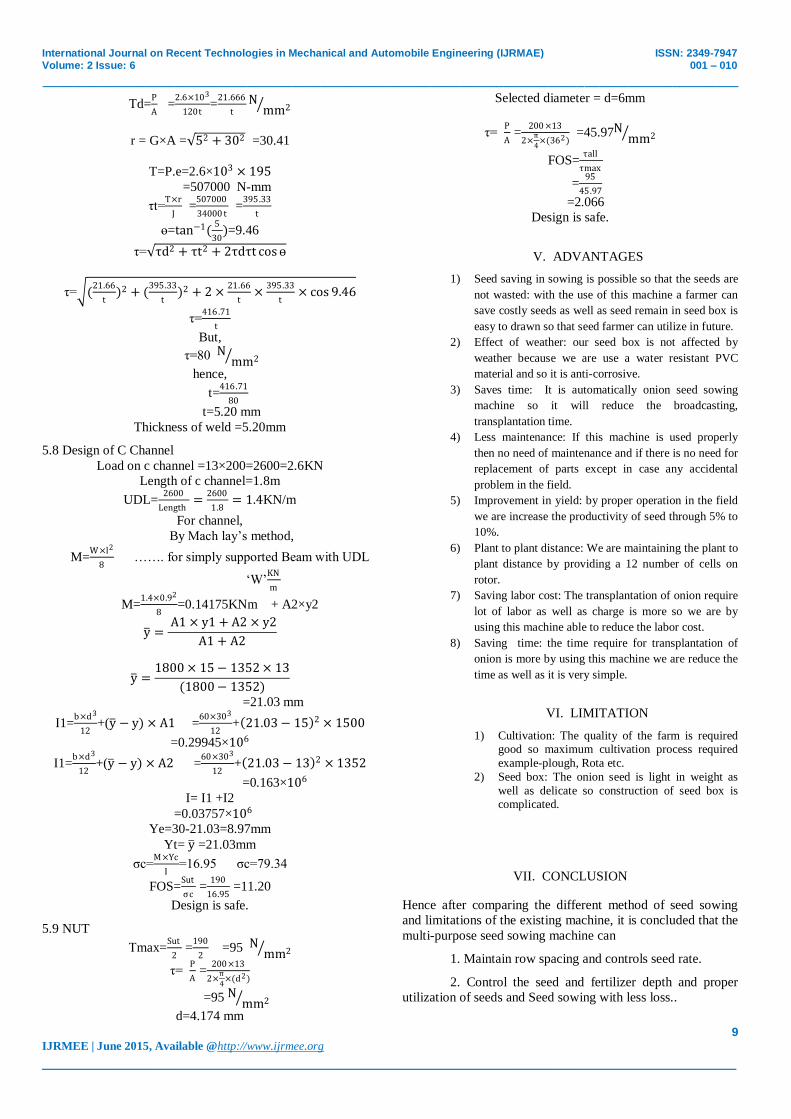
5.7 Design of Thickness of Weld
x = 30
y = 05
A=A1+A2
=60t+60t
=120t
Ixx=2×[0+ A1(y )2]
=2×60t×52
=3000t mm4
Iyy=2×(1
12) × l13 × t
=2×(1
12) × 603 × t
=36000t mm4
I=Ixx +Iyy
=39000t mm4
International Journal on Recent Technologies in Mechanical and Automobile Engineering (IJRMAE) ISSN: 2349-7947 Volume: 2 Issue: 6 001 – 010
_______________________________________________________________________________________________
9 IJRMEE | June 2015, Available @http://www.ijrmee.org
_______________________________________________________________________________________
Τd=P
A =
2.6×10³
120t=
21.666
tN
mm2
r = G×A = 52 + 302 =30.41
T=P.e=2.6×103 × 195
=507000 N-mm
τt=T×r
J =
507000
34000 t =
395.33
t
ɵ=tan−1(5
30)=9.46
τ= τd2 + τt2 + 2τdτt cosɵ
τ= (21.66
t)2 + (
395.33
t)2 + 2 ×
21.66
t×
395.33
t× cos 9.46
τ=416.71
t
But,
τ=80 N mm2
hence,
t=416.71
80
t=5.20 mm
Thickness of weld =5.20mm
5.8 Design of C Channel
Load on c channel =13×200=2600=2.6KN
Length of c channel=1.8m
UDL=2600
Length=
2600
1.8= 1.4KN/m
For channel,
By Mach lay’s method,
M=W×l2
8 ……. for simply supported Beam with UDL
‘W’KN
m
M=1.4×0.92
8=0.14175KNm + A2×y2
y = A1 × y1 + A2 × y2
A1 + A2
y =1800 × 15 − 1352 × 13
(1800 − 1352)
=21.03 mm
I1=b×d3
12+(y − y) × A1 =
60×303
12+ 21.03 − 15 2 × 1500
=0.29945×10⁶
I1=b×d3
12+(y − y) × A2 =
60×303
12+ 21.03 − 13 2 × 1352
=0.163×10⁶
I= I1 +I2
=0.03757×10⁶
Ye=30-21.03=8.97mm
Yt= y =21.03mm
σc=M×Yc
I=16.95 σc=79.34
FOS=Sut
σc =
190
16.95 =11.20
Design is safe.
5.9 NUT
Τmax=Sut
2 =
190
2 =95 N mm2
τ= P
A =
200×13
2×π
4×(d2)
=95 N mm2
d=4.174 mm
Selected diameter = d=6mm
τ= P
A =
200 ×13
2×π
4×(362)
=45.97Nmm2
FOS=τall
τmax
=95
45.97
=2.066
Design is safe.
V. ADVANTAGES
1) Seed saving in sowing is possible so that the seeds are
not wasted: with the use of this machine a farmer can
save costly seeds as well as seed remain in seed box is
easy to drawn so that seed farmer can utilize in future.
2) Effect of weather: our seed box is not affected by
weather because we are use a water resistant PVC
material and so it is anti-corrosive.
3) Saves time: It is automatically onion seed sowing
machine so it will reduce the broadcasting,
transplantation time.
4) Less maintenance: If this machine is used properly
then no need of maintenance and if there is no need for
replacement of parts except in case any accidental
problem in the field.
5) Improvement in yield: by proper operation in the field
we are increase the productivity of seed through 5% to
10%.
6) Plant to plant distance: We are maintaining the plant to
plant distance by providing a 12 number of cells on
rotor.
7) Saving labor cost: The transplantation of onion require
lot of labor as well as charge is more so we are by
using this machine able to reduce the labor cost.
8) Saving time: the time require for transplantation of
onion is more by using this machine we are reduce the
time as well as it is very simple.
VI. LIMITATION
1) Cultivation: The quality of the farm is required good so maximum cultivation process required
example-plough, Rota etc.
2) Seed box: The onion seed is light in weight as
well as delicate so construction of seed box is complicated.
VII. CONCLUSION
Hence after comparing the different method of seed sowing
and limitations of the existing machine, it is concluded that the
multi-purpose seed sowing machine can
1. Maintain row spacing and controls seed rate.
2. Control the seed and fertilizer depth and proper
utilization of seeds and Seed sowing with less loss..
International Journal on Recent Technologies in Mechanical and Automobile Engineering (IJRMAE) ISSN: 2349-7947 Volume: 2 Issue: 6 001 – 010
_______________________________________________________________________________________________
10 IJRMEE | June 2015, Available @http://www.ijrmee.org
_______________________________________________________________________________________
3. Perform the various simultaneous operations and
hence saves labor requirement, labor cost, labor time, total
cost of saving and can be affordable for the farmers.
As engineers we appreciate how does technology
affect our life in a positive way, with huge effects, since the
technology and mechanical engineering has demonstrated our
new world and we are living in the speed, where time is
important everyone everywhere are looking forward to do
their business with less effort and short time.
So we develop onion seed sowing machine to save
effort and time of human.
REFERANCE
[1] Prof. R.V. Jadhav - Performance evaluation of tractor drawn
multicrop planter for sowing of ground nut
[2] Mr. Hase Sunil. [M.P.K.V.](2008-09) – Development and
performance evaluation of multicrop planter for low HP tractor (18.5Hp)
[3] Miss Deshpande Shital. .[M.P.K.V.] (2010-11) -Performance
Evaluation of Bullock Drawn Light-Weight Jyoti multi crop
planter
[4] Design Data-PSG Publication.(page no. 1.1 to 9.7)
[5] Gupta & Khurmi.-Machine Design- (Page no. 150 to 421)
[6] V. B. Bhandari- Design of Machine Elements (Page no. 127 to
558)
[7] Ram Kharche -Food production (Page no. 32 to 58)