Embed Size (px)
Citation preview

Design and Fabrication of an Injection Tool for Neuromuscular
Microstimulators
HILTON M. KAPLAN1,2 and GERALD E. LOEB
1
1Alfred Mann Institute for Biomedical Engineering, University of Southern California, 1042 Downey Way, DRB-101,Los Angeles, CA 90089, USA; and 2PO Box 2337, Beverly Hills, CA 90213, USA
(Received 18 January 2008; accepted 6 June 2009; published online 24 June 2009)
Abstract—The injection of small implants into preciselylocalized sites within the body is a difficult task usuallyundertaken by surgeons or interventive radiologists. We havedesigned, produced and tested a simple tool for implantingBIONTM wireless microstimulators as an outpatient officeprocedure. The ability of BIONs to elicit a desired musclecontraction depends on their placement near the motor fibersthat innervate the muscle fibers, providing both the require-ment and a means for achieving accurate placement. Theimplant is preloaded into the tip of the cannula of a two-pieceinsertion tool made from non-conductive polymers. Trialstimulation pulses are generated by the implant as the tool ismanipulated into the desired position. The implant isreleased by withdrawing the cannula over the implant,preserving both the relative location of the implant’s elec-trodes with respect to the target and determining its desiredaxial orientation, which is important for implants containingmotion sensors. The BION Insertion Tool has been used forover 30 BION implants in human subjects to date.
Keywords—BION, Stimulation, Implantation, Hypodermic
needle, Finite element modeling, EMG, M-wave, Acceler-
ometer.
ABBREVIATIONS
AMI-USC Alfred Mann Institute at the Universityof Southern California
BIONTM BIOnic Neuron (an injectable, wirelessmicrostimulator)
BIT BION Insertion ToolFEA Finite Element Analysis
INTRODUCTION
The BIONTM microstimulator has a cylindricalshape and miniature size (2.1 mm diameter 9 16.0 mmlong) to facilitate nonsurgical placement of one or moreimplants via percutaneous injection rather than opensurgical procedures. The implant receives power anddigital command signals by inductive coupling to anexternal transmission coil, and it generates preciselycontrollable electrical pulses to stimulate nearby sen-sory or motor nerve fibers.10,11 The selectivity andefficacy of stimulation depends largely on the place-ment of its output electrode with respect to nearbynerve fibers. Multiple BION implants have been used toproduce coordinated contractions of individual musclesto prevent disuse atrophy,7 and to restore functionallimb movements in patients with upper motor neuronlesions (e.g., stroke and spinal cord injury).6 Weanticipate that such functional electrical stimulationwill benefit eventually from closed-loop feedback fromsensors incorporated into these implants,15 includingmultiaxial accelerometers whose axial orientation isimportant for their function.18,19
In order to inject these devices in a simple yet highlyaccurate manner, we have designed, built and tested theBION Insertion Tool (BIT) described herein, which isnow in clinical use (Figs. 1 and 2). A simple two-pieceneedle-like insertion tool houses the microstimulator,and enables stimulation pulses from the microstimula-tor to be delivered through its tip while the BIT isdirected toward the target. The basic design is suited toimplanting any cargo of similar form-factor (e.g., drugimplants, chemotherapeutic agents, transplanted tis-sues and cell cultures, radiotherapeutic beads, etc.).
Context and History
The design detailed here evolved through severaliterations based on systematic review of manufacturingand clinical experience. The resultant BIT has been
Address correspondence to Hilton M. Kaplan, PO Box 2337,
Beverly Hills, CA 90213, USA. Electronic mail: hkaplan@alumni.
usc.edu
Annals of Biomedical Engineering, Vol. 37, No. 9, September 2009 (� 2009) pp. 1858–1870
DOI: 10.1007/s10439-009-9739-5
0090-6964/09/0900-1858/0 � 2009 Biomedical Engineering Society
1858
produced by the Alfred Mann Institute for BiomedicalEngineering at the University of Southern California(AMI-USC), and has been used successfully for over30 BION implants in human subjects to date.
Previous BION Implantation Method and Concerns
Prior to the BIT, clinical implantation of BIONswas carried out using a modified intravenous drip set
(AngiocathTM; BD Medical, Franklin Lakes, NJ).Electrical stimulation was used to identify the ideallocation for the BION, via the tip of an otherwiseinsulated 17G needle that constituted a sharp, stifftrocar within a 12G, soft plastic sheath that provided acannula. The needle was then withdrawn to leave theplastic cannula in situ. The BION was manuallyinserted into the cannula and extruded from the distalend with the help of a pushrod. The cannula and
from tip
from backcannula handle peg
probe handle (outer handle)
probe
Probe Unit
Cannula Unit
cannula
cannula handle (inner handle)
10 cm
(a)
released
rotate peg along track to withdraw cannula and release / unsheathe BION
(b)
(c)
BION
probe
dimple indents
conduction holes
loaded
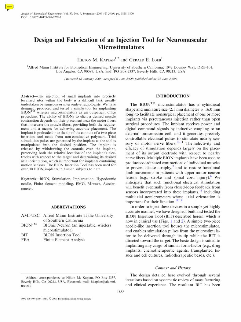
FIGURE 1. (a) The BIT comprises two units: the Cannula Unit is slid over the probe, so that its handle comes to lie within theProbe Unit’s handle. The peg screws into the cannula handle through the open track in the probe handle, where it is held by lockingresistances in that track. These lock the BIT in either of its loaded or released configurations. (b) The BION is released/unsheathedby the gunbolt action of the peg, which withdraws the cannula from over the probe and BION, while these both remain in position.(c) The BION is loaded into the distal cannula to abut against the probe tip, and is secured by opposing dimple indents from thecannula wall. The BION’s electrodes contact body fluids via the cannula’s conduction holes and distal opening. Designs preparedusing Autodesk InventorTM (Autodesk Inc., San Rafael, CA).
Microstimulator Implantation Tool: Design & Fabrication 1859
pushrod were then removed. Concerns with this tech-nique included: exposure of the BION to handlingrisks and potential for damage and contamination;drift from the implantation site during handling andextrusion; difficulty delivering the implant through anupward directed cannula; inability to predetermine theimplant’s axial orientation; and perhaps most impor-tant, the inability to test the BION in situ priorto release. The BIT described here was designed toaddress all of these issues.
Design Requirements
(1) Minimal tissue trauma(2) Small profile (no bigger than the 12G tool pre-
viously used)(3) Accurate localization (via electrical stimulation
and/or radiologic screening)(4) Complete protection of the implant throughout
delivery(5) Functional testing in situ, in real-time throughout
delivery(6) Retrieval of implant at any point prior to release(7) Ability to inject or withdraw fluids at tool tip(8) Control of axial orientation at delivery (impor-
tant for implants containing motion sensors)(9) Simple and intuitive operation
(10) Operable in any position or orientation(11) Minimal handling of the BION during implan-
tation(12) Biocompatible materials for brief contact with
tissue(13) Sterilizable by steam autoclave (current validated
method for BION implants), or gas, e.g., ethyleneoxide (ETO) for mass production
Strategy
Hypodermic needles that become disabled auto-matically after use are being developed to avoid the
hazards of unsterile re-use and accidental needle-stickinjury.3,9,17 One approach is to use thermoplastic poly-mers instead of metal because they can be dulled andsealed by applying moderate heat. Because plastic nee-dles buckle more easily than metal ones, the develop-ment of such needles to date has been limited toapplications that require short, fine needles, such as forimmunization programs and insulin delivery, e.g.,12.7 mm (0.5¢¢) length 9 22G (OD 0.7 mm (0.028¢¢), ID0.4 mm (0.016¢¢)).8 The BIT requires a much largergauge (OD 2.8 mm (0.110¢¢), ID 2.2 mm (0.085¢¢) =
12G) and shank length (100.0 mm to reach deepmuscles), posing various challenges for design andfabrication.
The main decision was to deliver the BION implantspreloaded into the tool from which they would bereleased. The BION itself would then generate the trialstimulation pulses required to determine its location byphysiological monitoring of the evoked response (e.g.,visible or palpable muscle twitch or electrophysiologi-cally recordedM-wave). For this to work, the tool mustnot interfere with the RF magnetic field that powersand controls the implant, and it must not block or shortthe stimulation pulses that it generates from passingthrough the target tissue outside the tool. These sec-ondary requirements, in turn, mandate the use ofelectrically and magnetically non-interfering materials(non-conductive and non-ferrous), plus fenestrations topermit egress of stimulation currents. Those materialsmust then provide the strength, biocompatibility andmanufacturability to achieve the rest of the require-ments. With suitable materials in hand, the rest of thedesign could focus on the ergonomics of loading andstabilizing the implant and releasing it precisely at thetarget site, which is described first to orient the readerto the mechanical analysis that follows.
The BIT has two main parts that move relative toeach other to release the implant: a plastic cannulawith a sharpened tip, and a probe within the cannulabehind the BION (Fig. 1). The probe is attached to themain body of the handle so that the operator naturallytends to stabilize this part of the tool with respect tothe target site. The cannula is attached to a gun-bolt-like assembly within the handle that allows it to bewithdrawn over the probe and implant to effect release.After assembly of the BIT, the BION is loaded via thedistal end of the cannula so that its Ir electrode abutsthe probe tip and its Ta electrode (effective cathode forstimulation pulses) lies exposed just within the bevel ofthe needle. The BION is retained in this loaded posi-tion and axial orientation by friction between its glasscapsule and two opposing dimple indents created bymechanically deforming the walls of the cannula(Fig. 1c). The BIONs axial orientation is set at loadingrelative to the cannula handle peg position (taking into
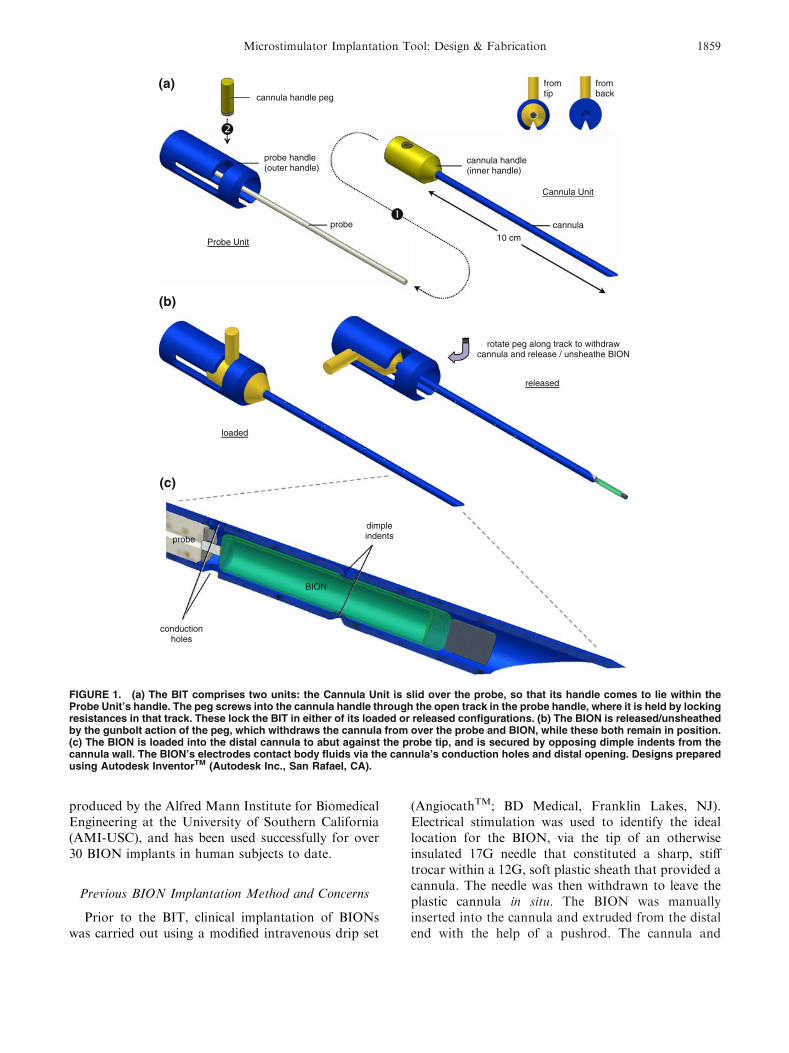
FIGURE 2. The BIT loaded with a BION, in sterile packagingready for shipping. Note the window cut-out in the cardboardtray beneath the BION chamber, to allow functional testingafter packaging and sterilization.
H. M. KAPLAN AND G. E. LOEB1860
account the 90� axial role that will be associated withdeployment), so that the clinician is able to orient theBION axially as desired at insertion. The cannula’ssharp tip is double-beveled to minimize the stress ofimplantation. The loaded BION–BIT is secured in acustomized cardboard tray, which has a window cut-out beneath the BION chamber for functional testingafter packaging and sterilization (Fig. 2). We havedetermined previously that the voltage change pro-duced on the electrodes in air when a stimulationcommand is received can be detected by capacitivecoupling to electrodes that are sufficiently close(<2.0 mm). The entire assembly is sealed in aTyvekTM pouch, sterilized and delivered for implan-tation as a single unit.
METHODS
Needle Tip Stress Profile
In order to choose an appropriate material for theBIT cannula, we needed to ascertain the forces that itwould have to withstand at its tip during insertion andmovement through muscle. A stainless ~12G steel tube(OD 2.8 mm (0.110¢¢), ID 2.0 mm (0.080¢¢)) was fash-ioned into a needle with a double-beveled tip. Twostrain gauges (BLH SR-4�; Vishay Micro-Measure-ments, Raleigh, NC) were recessed onto opposite sidesof the needle tip, and their connections brought outthrough the proximal end of the needle to an amplifiedWheatstone bridge configuration (LM6132 dual oper-ational amplifier; National Semiconductor, SantaClara, CA). The system was calibrated using a forcegauge (FG-5000; Extech Instruments, Waltham, MA)to exert lateral bending tip forces; it exhibited a linearoutput relationship up to 6.4 N. The needle was usedto measure lateral forces during four repetitions of
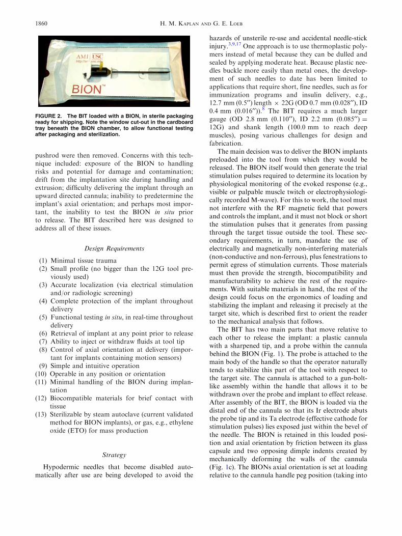
each of the following five use-cases in a large block ofporcine muscle: (1) inserting through fascia; (2) tra-versing parallel to muscle fibers; (3) traversing trans-verse to muscle fibers; (4) hitting up against bone withreasonable surgical caution; (5) hitting up against bonevigorously and recklessly (Fig. 3). The average peakforce experienced by the tip was determined for eachuse-case.
Wall Thickness Requirements and Material
In order to determine an appropriate polymericmaterial and wall thickness for the BIT, a flexuralstiffness was required that would be sufficiently strong(as determined by the section ‘‘Needle Tip Stress Pro-file’’ above), and yet would still provide similar han-dling characteristics as our original insertion tool. Thestiffness of the prior tool, based on the 12G Angiocathunit, was attributable largely to the 17G stainless steelneedle that formed a core within the soft polymericsheath. Therefore the aim for the BIT was to achieve atleast the same desired handling characteristics andsafety in bending as such a 17G stainless steel needle.The outside dimension (OD) of the BIT cannula waslimited by the 12G OD requirement (=2.8 mm(0.110¢¢)), and the inside dimension (ID) had to besufficient to clear the OD of the implant (=2.2 mm(0.085¢¢)). The required minimal flexural modulus for amaterial that would form the BIT cannula was com-puted as follows.
Basic stiffness equation for a cylinder in bending(supported at both ends; single load in center)12:
d ¼ PL3
48EIand I ¼ P
64ðD4
o �D4i Þ
where d = maximum deflection (m), P = load (N),L = length (m), E = Young’s modulus of elasticity
vigorously against bone
Fo
rce
(N
)
0
3
-3
6
Time (s) 100 20
parallel to fibers
Fo
rce
(N
)
0
3
-3
6
Time (s) 100 20
FIGURE 3. Needle tip stress profiles measured traversing parallel to muscle fibers (left) and hitting vigorously against bone(right).
Microstimulator Implantation Tool: Design & Fabrication 1861
(N m�2 or Pa), I = area moment of inertia (m4),Do = outer diameter (m), andDi = inner diameter (m).
To achieve the same desired stiffness coefficient(represented by P/d (N m�1), i.e., the force required toproduce a unit displacement) for both the givenstainless steel ‘‘S’’ cylinder at 17G and our desiredmaterial ‘‘M’’ cylinder at 12G:
PS
dS¼ PM
dM
So that ultimately:
EM ¼ ESD4
So �D4Si
D4Mo �D4
Mi
The ID that will accommodate the implant and the ODthat is required are both fixed (DMi, DMo), and theremaining variables are given for the stainless steeldevice (ES, DSo, DSi). Thus we can determine the req-uisite minimal flexural modulus for a material (EM), toform a BIT cannula with the same desired stiffness asour prior stainless steel version.
Selection and validation of the final material was aniterative process, involving a systematic search basedon the formalized requirements. The final polymerselected was a 30% glass reinforced liquid crystalpolymer (VectraTM B130; Ticona, Florence, KY). Themodels and experimental results described below arefor this material.
Conduction Hole Size and Configuration Experiments
Holes in the wall of the cannula are desirable forthree reasons: (1) to provide conduits so that the Irelectrodes of the BION become bathed with tissuefluids to allow testing during implantation; (2) to act asrule marks (10.0 mm intervals) to keep track of inser-tion depth; and (3) to permit ingress of steam or gasused to sterilize the less accessible regions of the loadedBIT. The following studies were used to ascertain theoptimal size, number, and configuration of holes thatwould meet these needs but not compromise adequatecannula wall strength:
Adequacy of Conduction Holes
The stimulus output circuitry of the BION generatescurrent-regulated pulses over the range 0.5–31.5 mAwith an available compliance voltage of 14 V. Theactual output current that it can produce will be lim-ited by the total load impedance (electrodes plus sur-rounding fluid and tissue) according to Ohm’s law.Experience has shown that it is useful for clinicians tobe able to apply test stimulus pulses of up to 10 mA atleast initially while searching for the desired low-threshold target (typically around 1 mA). The 10 mA
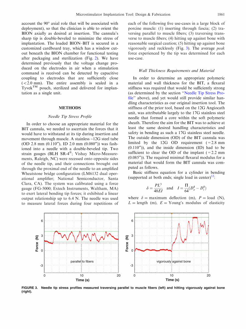
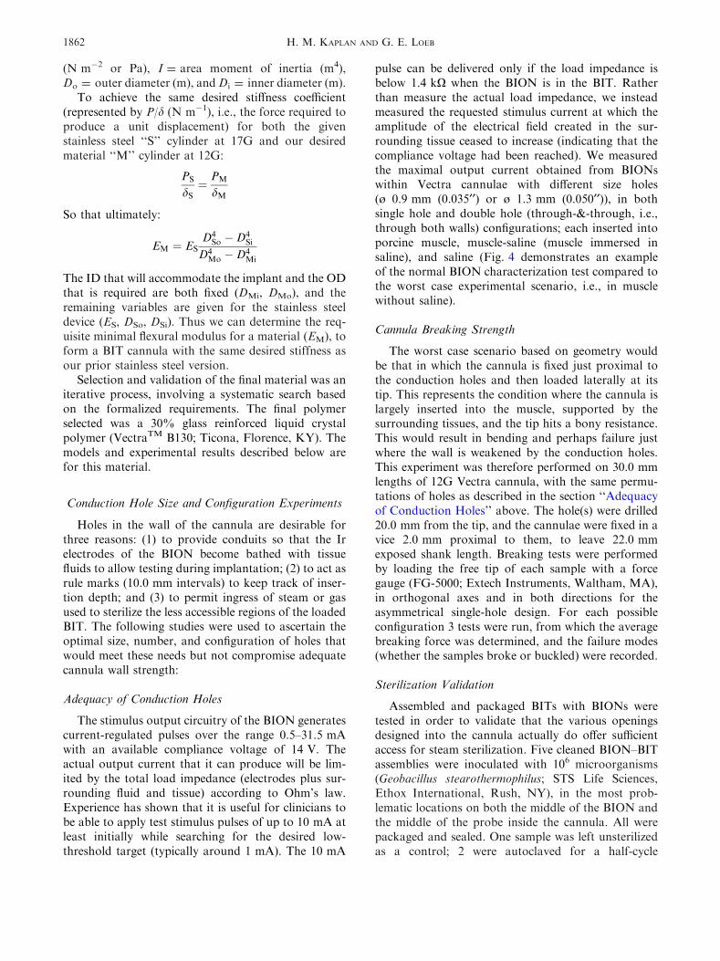
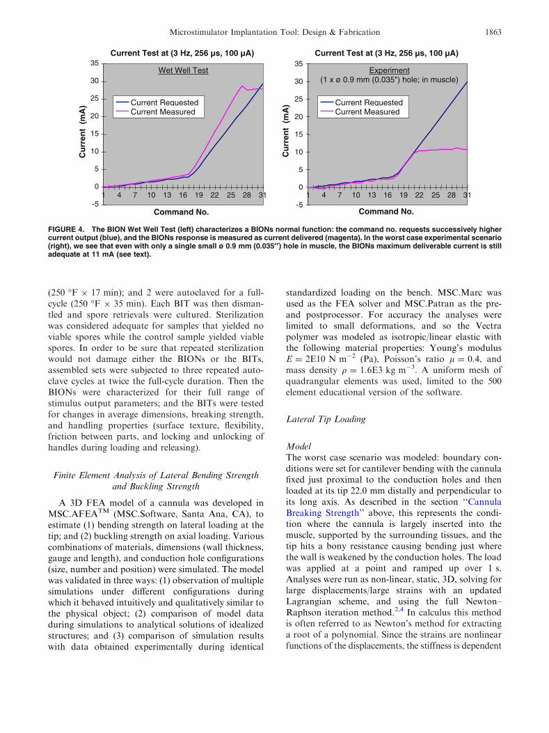
pulse can be delivered only if the load impedance isbelow 1.4 kX when the BION is in the BIT. Ratherthan measure the actual load impedance, we insteadmeasured the requested stimulus current at which theamplitude of the electrical field created in the sur-rounding tissue ceased to increase (indicating that thecompliance voltage had been reached). We measuredthe maximal output current obtained from BIONswithin Vectra cannulae with different size holes(ø 0.9 mm (0.035¢¢) or ø 1.3 mm (0.050¢¢)), in bothsingle hole and double hole (through-&-through, i.e.,through both walls) configurations; each inserted intoporcine muscle, muscle-saline (muscle immersed insaline), and saline (Fig. 4 demonstrates an exampleof the normal BION characterization test compared tothe worst case experimental scenario, i.e., in musclewithout saline).
Cannula Breaking Strength
The worst case scenario based on geometry wouldbe that in which the cannula is fixed just proximal tothe conduction holes and then loaded laterally at itstip. This represents the condition where the cannula islargely inserted into the muscle, supported by thesurrounding tissues, and the tip hits a bony resistance.This would result in bending and perhaps failure justwhere the wall is weakened by the conduction holes.This experiment was therefore performed on 30.0 mmlengths of 12G Vectra cannula, with the same permu-tations of holes as described in the section ‘‘Adequacyof Conduction Holes’’ above. The hole(s) were drilled20.0 mm from the tip, and the cannulae were fixed in avice 2.0 mm proximal to them, to leave 22.0 mmexposed shank length. Breaking tests were performedby loading the free tip of each sample with a forcegauge (FG-5000; Extech Instruments, Waltham, MA),in orthogonal axes and in both directions for theasymmetrical single-hole design. For each possibleconfiguration 3 tests were run, from which the averagebreaking force was determined, and the failure modes(whether the samples broke or buckled) were recorded.
Sterilization Validation
Assembled and packaged BITs with BIONs weretested in order to validate that the various openingsdesigned into the cannula actually do offer sufficientaccess for steam sterilization. Five cleaned BION–BITassemblies were inoculated with 106 microorganisms(Geobacillus stearothermophilus; STS Life Sciences,Ethox International, Rush, NY), in the most prob-lematic locations on both the middle of the BION andthe middle of the probe inside the cannula. All werepackaged and sealed. One sample was left unsterilizedas a control; 2 were autoclaved for a half-cycle
H. M. KAPLAN AND G. E. LOEB1862
(250 �F 9 17 min); and 2 were autoclaved for a full-cycle (250 �F 9 35 min). Each BIT was then disman-tled and spore retrievals were cultured. Sterilizationwas considered adequate for samples that yielded noviable spores while the control sample yielded viablespores. In order to be sure that repeated sterilizationwould not damage either the BIONs or the BITs,assembled sets were subjected to three repeated auto-clave cycles at twice the full-cycle duration. Then theBIONs were characterized for their full range ofstimulus output parameters; and the BITs were testedfor changes in average dimensions, breaking strength,and handling properties (surface texture, flexibility,friction between parts, and locking and unlocking ofhandles during loading and releasing).
Finite Element Analysis of Lateral Bending Strengthand Buckling Strength
A 3D FEA model of a cannula was developed inMSC.AFEATM (MSC.Software, Santa Ana, CA), toestimate (1) bending strength on lateral loading at thetip; and (2) buckling strength on axial loading. Variouscombinations of materials, dimensions (wall thickness,gauge and length), and conduction hole configurations(size, number and position) were simulated. The modelwas validated in three ways: (1) observation of multiplesimulations under different configurations duringwhich it behaved intuitively and qualitatively similar tothe physical object; (2) comparison of model dataduring simulations to analytical solutions of idealizedstructures; and (3) comparison of simulation resultswith data obtained experimentally during identical
standardized loading on the bench. MSC.Marc wasused as the FEA solver and MSC.Patran as the pre-and postprocessor. For accuracy the analyses werelimited to small deformations, and so the Vectrapolymer was modeled as isotropic/linear elastic withthe following material properties: Young’s modulusE = 2E10 N m�2 (Pa), Poisson’s ratio l = 0.4, andmass density q = 1.6E3 kg m�3. A uniform mesh ofquadrangular elements was used, limited to the 500element educational version of the software.
Lateral Tip Loading
ModelThe worst case scenario was modeled: boundary con-ditions were set for cantilever bending with the cannulafixed just proximal to the conduction holes and thenloaded at its tip 22.0 mm distally and perpendicular toits long axis. As described in the section ‘‘CannulaBreaking Strength’’ above, this represents the condi-tion where the cannula is largely inserted into themuscle, supported by the surrounding tissues, and thetip hits a bony resistance causing bending just wherethe wall is weakened by the conduction holes. The loadwas applied at a point and ramped up over 1 s.Analyses were run as non-linear, static, 3D, solving forlarge displacements/large strains with an updatedLagrangian scheme, and using the full Newton–Raphson iteration method.2,4 In calculus this methodis often referred to as Newton’s method for extractinga root of a polynomial. Since the strains are nonlinearfunctions of the displacements, the stiffness is dependent
Cu
rren
t (
mA
)
-5
0
5
10
15
20
25
30
35
1 4 7 10 13 16 19 22 25 28 31
Command No.
Current Test at (3 Hz, 256 µs, 100 µA)
Wet Well Test
Current RequestedCurrent Measured
Current Test at (3 Hz, 256 µs, 100 µA)
Command No.
Cu
rren
t (
mA
)
-5
0
5
10
15
20
25
30
35
1 4 7 10 13 16 19 22 25 28 31
Experiment(1 x ø 0.9 mm (0.035") hole; in muscle)
Current RequestedCurrent Measured
FIGURE 4. The BION Wet Well Test (left) characterizes a BIONs normal function: the command no. requests successively highercurrent output (blue), and the BIONs response is measured as current delivered (magenta). In the worst case experimental scenario(right), we see that even with only a single small ø 0.9 mm (0.035¢¢) hole in muscle, the BIONs maximum deliverable current is stilladequate at 11 mA (see text).
Microstimulator Implantation Tool: Design & Fabrication 1863
on the displacements. Therefore, the solution of thedisplacements cannot be obtained in a single step, andso a series of increments are combined with iterativeequilibrium corrections at every step.
TheoreticalUsing the Euler–Bernoulli beam equation12:
rmax ¼MbroI
where rmax = bending stress (N m�2 or Pa), Mb =
bending moment at the neutral axis (N m), ro = outerradius, i.e., perpendicular distance to the neutral axis(m), and I = area moment of inertia about the neutralaxis (m4).
Mb ¼ F� ‘
where F = tip bending force (N), and ‘ = length (m).
I ¼ P4ðr4o � r4i Þ
for a cylinder (as above).
ExperimentalStandardized lateral tip loading tests of this sameworst case scenario were performed in the section‘‘Cannula Breaking Strength’’ above, and the resultscompared with the model and theoretical data derivedabove.
Axial Loading
ModelA 100.0 mm length of cannula was modeled for axialbuckling, with and without 2 9 ø 1.3 mm (0.050¢¢)through-&-through holes 20.0 mm from the distal end.Boundary conditions were set as clamped-guided(proximal-distal). The buckling analysis was per-formed with a static linear compression step (smalldisplacements and strains), and by the full Newton–Raphson iteration method, with a Lanczos eigenvalueextraction scheme to derive the critical buckling loadPcr (N) from the eigenvalue EV and the applied loadPapplied (N):
Pcr ¼ EV� Papplied
TheoreticalUsing Euler’s buckling formula12:
Pcr ¼P2EI
L02
where E = Young’s modulus of elasticity (N m�2 orPa), I = area moment of inertia of the cross-section
(m4), and L¢ = effective length of the cylinder (m),which depends on the boundary conditions:
L0 ¼ Lffiffiffiffi
Cp
where C is a function of end constraint (for clamped-guided C = 1.0).
I ¼ P4ðr4o � r4i Þ
for a cylinder (as above).
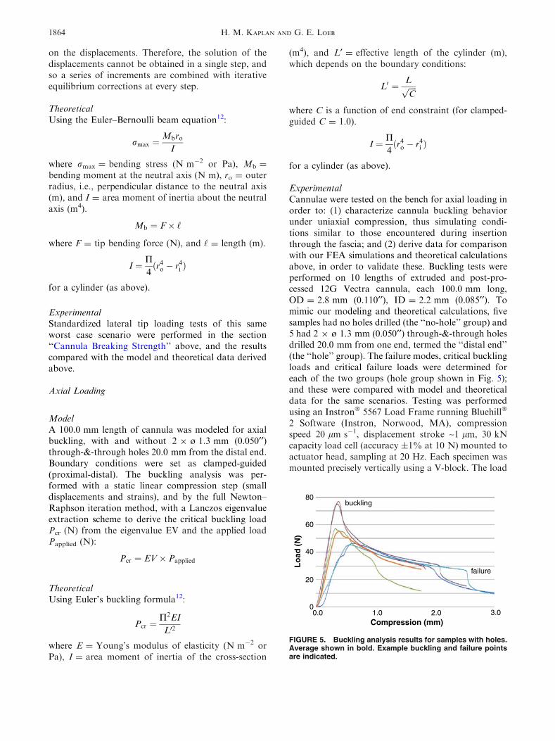
ExperimentalCannulae were tested on the bench for axial loading inorder to: (1) characterize cannula buckling behaviorunder uniaxial compression, thus simulating condi-tions similar to those encountered during insertionthrough the fascia; and (2) derive data for comparisonwith our FEA simulations and theoretical calculationsabove, in order to validate these. Buckling tests wereperformed on 10 lengths of extruded and post-pro-cessed 12G Vectra cannula, each 100.0 mm long,OD = 2.8 mm (0.110¢¢), ID = 2.2 mm (0.085¢¢). Tomimic our modeling and theoretical calculations, fivesamples had no holes drilled (the ‘‘no-hole’’ group) and5 had 2 9 ø 1.3 mm (0.050¢¢) through-&-through holesdrilled 20.0 mm from one end, termed the ‘‘distal end’’(the ‘‘hole’’ group). The failure modes, critical bucklingloads and critical failure loads were determined foreach of the two groups (hole group shown in Fig. 5);and these were compared with model and theoreticaldata for the same scenarios. Testing was performedusing an Instron� 5567 Load Frame running Bluehill�
2 Software (Instron, Norwood, MA), compressionspeed 20 lm s�1, displacement stroke ~1 lm, 30 kNcapacity load cell (accuracy ±1% at 10 N) mounted toactuator head, sampling at 20 Hz. Each specimen wasmounted precisely vertically using a V-block. The load
Compression (mm)
Lo
ad (
N)
1.00.0 2.0 3.0 0
20
40
60
80
failure
buckling
FIGURE 5. Buckling analysis results for samples with holes.Average shown in bold. Example buckling and failure pointsare indicated.
H. M. KAPLAN AND G. E. LOEB1864
response was recorded as a function of uniaxial com-pressive displacement through buckling in all samples,and until the specimens failed (kinked or broke) in ninesamples (the first sample could not be run to failure asit was used to test the set-up and subjectively assess thebehavior: this sample was run at the machine’s currentdefault setting for termination at 40% of maximalload, which was reached without failure; all subsequentspecimens were run to 20% of maximal load and allultimately failed). Buckling was assumed to occur atthe maximal recorded load for each sample. Failurewas assumed to occur at the sudden drop in loadingforce after buckling (Fig. 5).
RESULTS
Needle Tip Stress Profile
Figure 3 shows examples of measurements of forceexperienced by the tip of a 12G needle. In this way theaverage peak forces for each of the following five use-cases were found to be: (1) inserting through fas-cia = 4.2 ± 0.2 N (3.9–4.4); (2) traversing parallel tomuscle fibers = 0.9 ± 0.1 N (0.8–1.0); (3) traversingtransverse to muscle fibers = 4.9 ± 0.1 N (4.8–5.0);(4) hitting bone with reasonable surgical caution =
5.3 ± 0.2 N (5.1–5.5); and (5) hitting bone vigor-ously = >7.3 ± 0.0 N (7.3–7.3; this fell within theearly non-linear portion of the system’s force–voltagerelationship). It is recognized that as each of thesevalues is the average of the peaks of only four similarruns, the ranges are narrow and the standard deviationsare small. It was thus ascertained that a 12G needle of anon-metal material must also be able to withstand atleast these forces under these same conditions.
Wall Thickness Requirements and Material
The minimal flexural modulus for a material toform a BIT cannula with the same desired stiffness asour prior stainless steel version was found to be18.0 GPa. A variety of materials that met this speci-fication were considered for their appropriateness toour other design requirements (see Discussion). Thefinal two were: (1) a 55% glass reinforced thermo-plastic polyester resin of modified PET (polyethyleneterephthalate) with E = 17.9 GPa (RyniteTM 555;DuPont, Wilmington, DE); and (2) a 30% glassreinforced liquid crystal polymer with E = 20.0 GPa(VectraTM B130; Ticona, Florence, KY). Vectra wasultimately selected for its preferred flexural modulusas well as a variety of other design considerationsdiscussed below.
Conduction Hole Size and Configuration Experiments
Adequacy of Conduction Holes
As expected, the results were spread across a spec-trum from the worst obtained with a single smaller holein muscle (Fig. 4), to the best obtained with largerdouble holes in saline. All configurations met the10 mA requirement, however, so the design of the holeswas based on the results of studies ‘‘Cannula BreakingStrength’’ and ‘‘Sterilization Validation’’ below.
Cannula Breaking Strength
By comparing breaking strengths with the knowntip forces that the cannula must be able to withstand(as per the section ‘‘Needle Tip Stress Profile’’ above),it was found that 2 9 ø 0.9 mm (0.035¢¢) holes wouldoffer sufficient strength, while still allowing adequateconduction as per the section ‘‘Adequacy of Conduc-tion Holes’’ above. In the case of the 2 9 ø 1.3 mm(0.050¢¢) hole samples, the average breaking strengthswere 9.9 ± 4.5 N (5.0–14.1) for lateral tip forcesexerted perpendicular to the axis of the holes, and8.1 ± 0.7 N (7.3–8.7) for lateral tip forces exertedparallel to the axis of the holes (this is of relevance tovalidating our FEA model described in the section‘‘Finite Element Analysis of Lateral Bending Strengthand Buckling Strength’’ below). Whether the failuremode consisted of buckling or breaking appeared to beuncorrelated with hole pattern or loading direction.
Sterilization Validation
After spore retrieval, positive cultures were foundon all sites of the control sample and on all sites of thehalf-cycle samples (250 �F 9 17 min). Negative cul-tures were found on all sites of the full-cycle samples(250 �F 9 35 min). This effective kill cycle was dou-bled to determine a final standard autoclave protocolof 250 �F 9 70 min. Both the BION and the BIT wereshown to adequately withstand this sterilization forthree cycles without degradation of their mechanical,electrical or biomaterial properties.
Finite Element Analysis of Lateral Bending Strengthand Buckling Strength
Lateral Tip Loading
ModelIn the model without holes, a lateral tip load of 5.0 Ngenerated a maximal tensile stress rmax = 90E6 N m�2
at the fixed end. When 2 9 ø 1.3 mm (0.050¢¢) holeswere added 20.0 mm from the tip (2.0 mm from the fixedend), for the same loading conditions: the maximaltensile stress increased to 110E6 N m�2 when the tip
Microstimulator Implantation Tool: Design & Fabrication 1865
load was applied perpendicular to the axis of the holes;and to 126E6 N m�2 when applied parallel to the axis ofthe holes. The model confirms that holes increase therisk of failure, particularly for forces parallel to theiraxis. In order to compute the forces at which thecannulae would break, Vectra was assumed to be non-deformable/non-plastic with a linear stress:force rela-tionship until breaking. For each scenario the resultswere extrapolated until the maximal tensile stressexceeded the published tensile breaking stress =
205E6 N m�2 (VectraTM B130 datasheet; Ticona,Florence, KY). The cannula was projected to break at9.4 N (=207E6 N m�2 tensile stress) for perpendicularstress, and at 8.2 N (=207E6 N m�2 tensile stress) forparallel stress.
TheoreticalUsing the Euler–Bernoulli beam equation with actualBIT parameter values for the no-hole scenariodescribed in the model above, the calculatedrmax = 80E6 N m�2, in reasonable agreement with90E6 N m�2 predicted by FEA above.
ExperimentalAs per the section ‘‘Cannula Breaking Strength’’above: with 2 9 ø 1.3 mm (0.050¢¢) holes the averagebreaking strengths found experimentally were 9.9 Nfor tip forces exerted perpendicular to the axis of theholes, and 8.1 N for tip forces exerted parallel to it.The model accurately predicts similar values for thesescenarios at 9.4 and 8.2 N, respectively (above), con-firming our assumption that the stress:force relation-ship for Vectra is linear until the cannula breaks.
Axial Loading
ModelIn samples without holes, for a unit compression load,the model gives an EV = 39.4, representing a bucklingload of 39.4 N, with a lateral displacement of 24.6 mm.The addition of 2 9 ø 1.3 mm (0.050¢¢) through-&-through holes 20.0 mm from the distal end results inan EV = 38.6, representing a reduced buckling load of38.6 N, with a slight increase in lateral displacement to24.7 mm.
TheoreticalUsing Euler’s buckling formula for a no-hole cylinder,calculated Pcr = 38.0 N, matching the model’s 39.4 Nsimulation value closely (within 4%).
ExperimentalFailure Modes: Of the 9 specimens run to failure, onlyone ‘‘hole’’ specimen broke (fractured through its
holes). All other failures in both no-hole and hole groupswere by buckling. All failures occurred at widely varyinglocations in all specimens; in the hole group none wererelated to the holes in either positionor axial orientation.
Critical Buckling Loads: Mean critical buckling loadfor all samples was 55.3 ± 13.7 N, at a compression of0.6 ± 0.3 mm. The critical buckling loads fell within awide range (39.4–77.0 N), the minimum of whichcorrelates well with our model predictions and theo-retical calculations above. For the small number ofsamples tested, there was no significant differencebetween the cannulae with and without holes.
Critical Failure Loads: After buckling, failureoccurred at a mean load for all samples of 27.8 ± 4.4 N,over a much narrower load range than for buckling(22.5–34.7 N), but at more widely varying degrees ofcompression (2.4 ± 1.1 mm). For the small number ofsamples tested, there was no significant differencebetween the cannulae with and without holes.
DISCUSSION
Material Selection
Materials have been selected so as to ensure that thecombined instrument meets the design requirements,particularly regarding strength, sharpness, biocom-patibility, sterilization and electrical resistance. Of allthe parts, the cannula’s properties are the most crucial,both mechanically so that it withstands insertionstresses and strains, and electromagnetically so that itdoes not interfere with the BIONs function as amicrostimulator. The cannula also must undergo crit-ical fabrication steps to produce its sharp, beveled tip,perforations and indentations.
We have calculated that a 12G cannula with a wall-thickness of 0.32 mm (0.0125¢¢) will have the same flex-ural strength as a standard 17G stainless steel needle if itis made from a material with a flexural modulus of atleast 18.0 GPa. To obtain this high degree of stiffness, apolymeric material generally requires longitudinal fiberfilling (e.g., carbon or glass). Filled plastics are generallymore suited to injection molding than extrusion, butextrusion is more desirable for the thin-walled cannula.The cannula material must also be non-ferrous andsufficiently non-conductive (such that it does not permiteddy currents), so as not to distort the electromagneticfield used to power the implant for testing it while it isstill housedwithin the cannula. Thematerial’s resistivitymust therefore be at least greater than that of body tis-sues (~1 X m). The polymer should also be impactresistant and suited to sterilization, e.g., autoclaving(softening temperature must exceed 250 �F) or ETO(ethylene oxide) gas sterilization for mass production.
H. M. KAPLAN AND G. E. LOEB1866
Based on these considerations, VectraTM B130 waschosen for the cannula (30% glass-filled liquid crystalpolymer, black; Ticona, Florence, KY). Vectra can bemolded or extruded. For cannula production it issimultaneously drawn and extruded (Precision Extru-sion, Glens Falls, NY). The raw stock is thenpost-processed by the manufacturer in a solid statepolymerization process. After extrusion the cannulaeare re-heated and held at the curing temperatureduring which time the polymers further cross-link,resulting in increases in molecular weight, melt tem-perature, tensile strength (up to 50%) and flexuralmodulus (up to 50–100%). The process results incannulae that fail less easily, tend to kink rather thanfracture, and are left with a smooth, even and shinyouter surface. This polished outer surface minimizesdrag through the tissues, while the luminal surface isadequately suited to movement over the probe andBION. Afterward the through-&-through conductionand depth-marking holes, and the beveled tip, are lasercut (Accu-Met Laser, Cranston, RI). Laser cuttingleaves smooth, precisely formed features (accuracy to0.025 mm (0.001¢¢)). The highly localized heat flashesthe edges, fusing them and leaving no torn or looseglass fibers exposed from the sealed polymer, as wouldoccur with drilling or machine cutting. Compared withconventional machining, this method is also moreaccurate, repeatable, and time and cost efficient. Thesize of the electrical conduction openings has beendetermined to allow adequate exposure of the elec-trodes to body fluids, while still maintaining sufficientstrength for even a clumsy insertion. Finally, the twoopposing dimple indents are made to hold the BION.First a small hole is created with a dental pick at eachsite, and then a customized 25.4 mm (1¢¢) micrometer isscrewed 0.9 mm (0.035¢¢) into the cannula wall at thosepoints. This leaves opposing detents of ~0.6 mm(0.025¢¢) each, protruding into the cannula’s lumen andagainst which the BION is loaded. If reloading of aBION is required during assembly, these dimples arecleared with a 2.2 mm (0.085¢¢) calibration pin, andrecreated at another point on the cannula’s circum-ference. This method is not particularly precise but itcan be used reliably to produce friction forces in thebroadly acceptable range of 0.5–5 N. A calibrated toolis used for loading the BION into the distal end of theBIT so that an acceptable holding force can be verified.Packaged BION–BIT assemblies were tested in 6 cross-country flights to ensure that they were not damagedor dislodged by normal air freight/postal handling.
Buckling analysis of the cannula has revealed that:(1) relative to the critical buckling loads found exper-imentally, the FEA model and theoretical calculationsprovide conservative results, offering a margin ofsafety; and (2) the cannulae will fail at their weakest
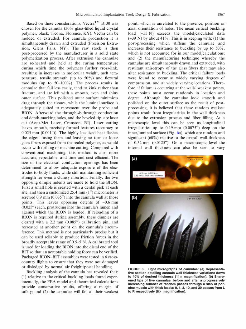
point, which is unrelated to the presence, position oraxial orientation of holes. The mean critical bucklingload (~55 N) exceeds the model/calculated data(~39 N) by about 41%. This is in keeping with: (1) thepost-processing which stiffens the cannulae andincreases their resistance to buckling by up to 50%,which is not accounted for in our model/calculations;and (2) the manufacturing technique whereby thecannulae are simultaneously drawn and extruded, withresultant anisotropy of the glass fibers that may alsoalter resistance to buckling. The critical failure loadswere found to occur at widely varying degrees ofcompression, and at widely varying locations. There-fore, if failure is occurring at the walls’ weakest points,these points must occur randomly in location anddegree. Although the cannulae look smooth andpolished on the outer surface as the result of post-processing, it is believed that these random weakestpoints result from irregularities in the wall thicknessdue to the extrusion process and fiber filling. At amicroscopic level this can be seen as longitudinalirregularities up to 0.19 mm (0.0075¢¢) deep on theinner/luminal surface (Fig. 6a), which are random andsignificant (60%) relative to the overall wall thicknessof 0.32 mm (0.0125¢¢). On a macroscopic level theinternal wall thickness can also be seen to vary
FIGURE 6. Light micrographs of cannulae: (a) Representa-tive section detailing cannula wall thickness variations downto 40% of desired thickness (113 magnification). (b) Sharp-ened tips of five cannulae, before and after a progressivelyincreasing number of random passes through a slab of por-cine muscle with thick fascia: 0, 1, 3, 10, and 30 passes from Lto R respectively (83 magnification).
Microstimulator Implantation Tool: Design & Fabrication 1867
somewhat as gentle undulations along its length (mostlikely due to subtle variations in the drawing speedduring extrusion).
The mean critical buckling load was compared toanticipated axial insertion forces for a needle in softtissue. Studies have shown that the axial load on aneedle during insertion into soft tissue is the summa-tion of different forces distributed along the needleshaft (cutting force, friction force and stiffness force),and that these forces can be modeled as functions ofposition (x) of the needle tip during insertion, to obtainresults comparable with experimental data1,5,14:
fneedleðxÞ ¼ fcuttingðxÞ þ ffrictionðxÞ þ fstiffnessðxÞ
Values for axial insertion forces range from ~1.45 Nrequired to puncture liver capsule for example (anal-ogous to fascia), up to ~14 N to puncture skin in vivo,with most published values falling in the 3–5 N rangefor needles with a ~22� bevel (the BIT bevel is 25�).13,14
The BIT is designed to be implanted via a stab incisionthrough the skin, so the largest axial forces shouldarise from penetrating fascia (1–3 N range). Even if itwere used to puncture skin directly, the ~55 N meancritical buckling load provides a safety factor of four-fold over the worst case puncture force of ~14 Nanticipated during implantation. Furthermore, in allbut one instance, the cannulae were found to kinkrather than fracture. This failure mode (large scaleplastic deformation) presents less of a hazard than thecatastrophic failures associated with buckling in morebrittle materials. Also of interest was how resilient thesharpened tip features would remain under these typesof loading. Figure 6b shows the magnified tips of 5cannulae, before and after a progressively increasingnumber of random passes through a slab of porcinemuscle with thick fascia (0, 1, 3, 10, and 30 passes). At89 magnification the tip features remained visiblyunaltered in all cases.
The role of FEA in the cannula development wasthreefold: (1) Modeling indicated that the empiricalexperimental results were consistent with expectations,as opposed to reflecting a random state of poorlycontrolled variables such as wall thickness and uni-formity. (2) Modeling predicted that it should not benecessary to include a probe or a BION within thecannula for testing, as the amount of deflection of thecannula wall before it started to fail catastrophicallyshould not exceed clearance to the implant nor theflexible probe. This was important so that the implantwould not be taking up any significant stress duringinsertion; and because these components wouldtherefore be unlikely to produce mechanical stressrisers at the probe/BION junction that could otherwisecause mechanical failures at lower force levels than
were predicted. Experimental findings also confirmedthat the failures occurred more proximally than wherethe BION would have been, i.e., where the bendingstresses were higher. (3) The validated FEA model willbe useful for future designs/other possible variants ofthe BIT.
The materials used for the remaining parts of theinstrument are less critical. We chose to make theprototypes described herein by machining and joiningof relatively simple components. The componentdesigns and materials are suitable for injection mold-ing, which would greatly reduce unit costs for massproduction:
� cannula handle and peg: polyetherimide (UltemTM,amber; SABIC Innovative Plastics, Pittsfield, MA);� probe: polycarbonate (MakrolonTM, clear/white;
Bayer MaterialScience, Pittsburgh, PA);� probe handle: carbon-filled PEEK (polyetheretherk-
etone, black; McMaster-Carr, Atlanta, GA).
The probe’s 21G central lumen, in addition toproviding injection/aspiration functionality to the BIT,also facilitates better extrusion tolerances by allowingdegassing during manufacture. Its clear color contrastswith the black cannula to enhance the visibility of thedepth-marking holes. All materials chosen interactwith each another and the cannula in a predictablefashion to meet the design requirements, e.g., to pro-vide sufficient stiffness, predictable locking andunlocking forces, friction and/or frictionless move-ments as required between parts and within tissues, etc.Further, they can easily be fused together using cya-noacrylate glue if necessary. They are also already inuse commercially for other medical applications suchas in laparoscope handles.
Preimplantation and Prerelease Testing
The two electrical conduction openings adjacent tothe BIONs Ir electrode (Fig. 1c), together with thecannula’s terminal opening adjacent to the Ta elec-trode, facilitate repeated stimulation at any point whiletraversing the tissue path so as to determine the desiredimplant location. Both the function of the implant andthe accuracy of its placement can be confirmed beforerelease. More systematic testing of incrementalrecruitment of the muscle can be obtained by recordingand measuring the M-wave produced by stimuluspulses of varying intensity above threshold. TheM-wave is the electrical potential produced by thesynchronous activity of those muscle fibers innervatedby the stimulated motor axons. The M-wave can berecorded from the skin surface or via an intramuscularEMG needle electrode. The digitized M-wave data can
H. M. KAPLAN AND G. E. LOEB1868
be used by a computer program to continuously adjustthe stimulus level to stay near threshold and to provideinformation about this threshold intensity via audiofeedback to the operator. This seems likely to speed theinsertion procedure and minimize the need for a tech-nically proficient assistant. The growth of the M-wavecan provide important information about the locationrelative to the nerve and its intramuscular branches.16
Implantation
General surgical principals teach the implantationof all foreign bodies by sterile, non-touch techniques.To that end, the transmission coil is either set uppreoperatively around but not contaminating the sur-gical field, or draped in a sterile see-through bag andbrought into the surgical field as required. In the for-mer case, the insertion site is prepared preoperativelywith antiseptic wash, the coil is placed around theperimeter of the insertion site, and the full area(including the coil) is draped with a sterile, adhesivepolyurethane film, e.g., OpSiteTM (Smith & Nephew,Largo, FL) or Steri-DrapeTM (3M, St. Paul, MN). Tominimize trauma, an EMG stimulating needle elec-trode (21G = ø ~0.8 mm (0.031¢¢) insulated may beused to locate an optimal point of stimulation beforethe larger BIT is introduced. The BIT has a largeV-shaped 45� groove (Fig. 1), aligned through bothhandles in the loaded configuration, so that it may beguided over and parallel to this stimulating electrode.Alternatively, the physician may prefer to use theEMG electrode to locate the motor point by the mostdirect route according to surface landmarks, even ifthis is perpendicular to the target nerve. The BION isthen implanted from a more distant location by tri-angulating toward the EMG electrode tip as a guide.In this way the BION can more likely be orientedparallel to the nerve and fascial planes, where it is lesslikely to experience motion or changes in recruitmentproperties during muscle activation or postural shifts.
Clinical Experience
Over the course of a year, both the BIT and theprior insertion apparatus were made available forimplants. At the discretion of the clinicians, of 33BIONs requiring implantation by injection, 30 BIONsin 16 patients were implanted using BITs. ThreeBIONs in 2 patients were implanted using the priorapparatus that permitted test stimuli to be appliedthrough its removable trocar because in these cases theexternal RF-coil was unable to activate the BIONs inthe surgical field. In general, the clinicians found theBIT preferable because it was simple, intuitive and easyto use, facilitating rapid and accurate placement.
CONCLUSIONS
The polymeric BIT described here takes advantageof very stiff, filled polymers, and laser fabricationtechniques that have only recently been developed.This permitted the design of a relatively large, long,strong and sharp needle-like tool that was both elec-trically non-conductive and electromagnetically inert(unique requirements for this particular application).The design, materials and validated analytical tech-niques can be readily adapted for other applicationswhere such properties may be desirable, e.g., drugimplants, chemotherapeutic agents, transplanted tis-sues and cell cultures, radiotherapeutic beads, etc. Thefriction fit and release mechanisms helped provide asimple, low-cost design that is easy and intuitive to use.
ELECTRONIC SUPPLEMENTARY MATERIAL
The online version of this article (doi:10.1007/s10439-009-9739-5) contains supplementary material,which is available to authorized users.
ACKNOWLEDGMENTS
Contributions to this research were made by RayPeck and Jasspreet Singh (AMI-USC, technical adviceand prototyping); Rahman Davoodi (AMI-USC,modeling); and Warren G. Haby (USC Department ofMechanical Engineering, buckling tests). All are fromthe University of Southern California, Los Angeles,CA, USA. The research has been funded predomi-nantly by the Alfred Mann Institute at the Universityof Southern California, Los Angeles, CA, USA; and inpart by NIH BRP Grant #R01EB002094. There are nofinancial relationships that may pose a conflict ofinterest.
REFERENCES
1Abolhassani, N., R. Patel, and M. Moallem. Needleinsertion into soft tissue: a survey. Med. Eng. Phys. 29(4):413–431, 2007. doi:10.1016/j.medengphy.2006.07.003.2Chandrupatla, T. R., and A. D. Belegundu. Introductionto Finite Elements in Engineering (2nd ed.). New Delhi:Prentice-Hall, 1997.3Clements, C. J., M. T. Aguado, and L. Jodar. Technologiesto improve immunisation safety [Review]. Drug Saf.24(14):1019–1026, 2001. doi:10.2165/00002018-200124140-00001.4Cook, R. D., D. S. Malkus, M. E. Plesha, and R. J. Witt.Concepts and Applications of Finite Element Analysis(4th ed.). New York: John Wiley & Sons, 2002.
Microstimulator Implantation Tool: Design & Fabrication 1869
5DiMaio, S. P., and S. E. Salcudean. Needle insertionmodeling and simulation. IEEE Trans. Robot. Autom.19(5):864–875, 2003. doi:10.1109/TRA.2003.817044.6Dupont, A. C., S. D. Bagg, L. L. Baker, J. L. Creasy,C. Romano, D. Romano, F. J. R. Richmond, andG. E. Loeb. First patients with BION implants for thera-peutic electrical stimulation. Neuromodulation 7:38–47,2004. doi:10.1111/j.1525-1403.2004.04005.x.7Dupont, A. C., F. J. R. Richmond, and G. E. Loeb. Pre-vention ofmuscle disuse atrophy by low-frequency electricalstimulation in rats. IEEE Trans. Neural Syst. Rehabil. Eng.11(3):218–226, 2003. doi:10.1109/TNSRE.2003.817674.8Kim, H., and J. S. Colton. Fabrication and analysis ofplastic hypodermic needles. J. Med. Eng. Technol. 29(4):181–186, 2005. doi:10.1080/03091900412331289898.9Lloyd, J. S., and J. B. Milstien. Auto-disable syringes forimmunization: issues in technology transfer. Bull. WorldHealth Organ. 77(12):1001–1007, 1999.
10Loeb, G. E. and F. J. R. Richmond. BION implants fortherapeutic and functional electrical stimulation. In: NeuralProstheses for Restoration of Sensor and Motor Function,edited by J. K. Chapin, K. A. Moxon, and G. Gaal.Naples, FL: CRC Press, 2001, pp. 75–99.
11Loeb, G. E., F. J. R. Richmond, and L. L. Baker. TheBION devices: injectable interfaces with peripheral nervesand muscles. Neurosurg. Focus 20(5):E2, 2006.
12Ozkaya, M., and M. Nordin. Fundamentals of Biome-chanics: Equilibrium, Motion, and Deformation (2nd ed.).New York: Springer, p. 183, 1999.
13Podder, T. K., J. Sherman, D. P. Clark, E. M. Messing,D. J. Rubens, J. G. Strang, L. Liao, R. A. Brasacchio,
Y. Zhang, W. S. Ng, and Y. Yu. Evaluation of roboticneedle insertion in conjunction with in vivo manualinsertion in the operating room. In: IEEE InternationalWorkshop on Robots and Human Interactive Communi-cation, 2005, pp. 66–72.
14Simone, C., and A. M. Okamura. Modeling of needleinsertion forces for robot-assisted percutaneous therapy.In: Proc. 2002 Int. IEEE Robotics and Automation Conf.,2002, pp. 2085–2091.
15Tan, W., Q. Zou, E. S. Kim, and G. E. Loeb. Sensinghuman arm posture with implantable sensors. In: Proc.26th Int. IEEE Eng. Med. Biol. Conf., 2004, pp. 4290–4293.
16Weber, D. J., R. B. Stein, K. M. Chan, G. E. Loeb, F. J. R.Richmond, R. Rolf, K. James, S. L. Chong, A. K.Thompson, and J. Misiaszek. Functional electrical stimu-lation using microstimulators to correct foot drop: a casestudy. Can. J. Physiol. Pharm. 82:784–792, 2004. doi:10.1139/y04-078.
17World Health Organization. Safety of injections: WHO-UNICEF-UNFPA joint statement on the use of auto-dis-able syringes in immunizations services. WHO/V&B/99.25,1999.
18Zou, Q., W. Tan, E. S. Kim, and G. E. Loeb. Single- andtriaxis piezoelectric-bimorph accelerometers. J. Microelec-tromech. Syst. 17(1):45–57, 2008. doi:10.1109/JMEMS.2007.909100.
19Zou, Q., W. Tan, E. S. Kim, J. Singh, and G. E. Loeb.Implantable biaxial piezoresistive accelerometer for senso-rimotor control. In: Proc. 26th Int. IEEE Eng. Med. Biol.Conf., 2004, pp. 4279–4282.
H. M. KAPLAN AND G. E. LOEB1870