Embed Size (px)
Citation preview

Page | 119
Design and fabrication of 90 degree
Steering Mechanism
Bachhav Ajinkya, Narsale Umesh, Attar Sohel, Kalane Kiran
Abstract—The Soft Car design proposal has swing 90 degrees. It can pull up alongside a parkingspace and drive in sideways. Conventional steering mechanism involves either the use of Ackerman or Davis steering systems. The disadvantage associated with these systems is the minimum turning radius that is possible for the steering action. This difficulty that is associated with the conventional methods of steering is eliminated by employing a four wheel 90 degree steering system. This innovation promises to ease the task of parking on narrow Cambridge streets. The most striking elements of the car are wheels that incorporate electric motors and the suspension inside their circumference. By working through the problem so logically and indeed unemotionally we will anticipate discovering new possibilities. "We want to step back and rethink the automobile from scratch.Arrange steering system at front and rear side. When steering wheel will be rotate.
Keywords-Steering,90degree,rack and pinion,zero turning radius.
————————————————————
INTRODUCTION
The advanced new technology has led to various
modifications in the automobile sector. Out Of these,
zero degree turning radius which is being analyzed in
various vehicles e.g. hurricane jeep, JCB, Nano Pixel
etc . The turning circle of a vehicle is the diameter de-
scribed by theoutside wheels when turning on full
lock. There is no hard and fast formula to calculate
the turning circle but it can be calculated using this;
Turning circle radius= (track/2) + (wheelbase/sin (av-
erage steer angle)).
Zero degree turning radius of a vehicle implies the
vehicle rotating about an axis passing through the
center of gravity of vehicle i.e. the vehicle turning at
the same place, where it is standing. No extra space is
required to turn the vehicle. So vehicle can be turned
in the space equal to the length of the vehicle itself.
This technology exists in heavy earth movers like
excavator which consists of two parts i.e. the upper
part cabin and lower part crawler chain. The upper
part of excavator can rotate about its center, so that
the direction of cabin can be changed without chang-
ing direction of lower part. Conventional steering me-
chanism involves either the use of Ackerman or Davis
steeringSystem.
The disadvantage associated with these systems is
the minimum turning radius that is possible for the
steering action. This difficulty that is associated with
the conventional methods of steering is eliminated by
employing a 90-degree wheel steering system. In this
system vehicle front wheels will turn with help of rack
and pinion as the direction of both wheels get parallel
turn with 90 degree angles. Same phenomenon oc-
curs at the rear wheels with the help of rack and pi-
nion.
International Journal of Scientific & Engineering Research Volume 11, Issue 7, July-2020 ISSN 2229-5518
97
IJSER © 2020 http://www.ijser.org
IJSER
Page | 120
PROBLEM STATEMENT:
The most frequently used type of steering, are us-
ing the front two wheels of the vehicle. This type of
steering suffers from the comparatively larger turning
circle and the extra effort required by the driver to
negotiate the turn.many of the metro and urban city
people are face problems in the traffic due to num-
bers of the vehicle and limited space for turning.
Components Used:
1. Rack and pinion: A rack and pinion is a type of
linear actuator that comprises a pair of gears
which convert rotational motion into linear mo-
tion. A circular gear called "the pinion" engages
teeth on alinear gear bar called the rack"; rota-
tional motion applied to the pinion causes the
rack to move relative to the pinion, thereby trans-
lating the rotational motion of the pinion into li-
near motion.Rack and pinion gears are used to
convert rotation into linear motion. The flat,
toothed part is the rack and the gear is the pinion.
2. Bevel gear:Bevel gears that have pitch angles of
greater than ninety degrees have teeth that point
inward and are called internal bevel gears. Bevel
gears that have pitch angles of exactly 90 degree-
shave teeth that point outward parallel with the
axis and resemble the points on a crown.
3. Motor drive:DC motor is any of a class of rotary
electrical machines that converts direct current
electrical energy into mechanical energy. The
most common types rely on the forces produced
by magnetic fields. Nearly all types of DC motors
have some internal mechanism, either electrome-
chanical or electronic, to periodically change the
direction of current flow in part of the motor.
BASIC DESIGN CALCULATIONS:
Length travelled by rack for 300
rotation
Tan 30 = Opp/Adj=X/100
X = 58 mm
For 300 of wheel rotation link has to move 58mm
Pitch of rack = 5mm
No of teeth in engagement with rack and pinion = 2
So At a time rack will move 10 mm
International Journal of Scientific & Engineering Research Volume 11, Issue 7, July-2020 ISSN 2229-5518
98
IJSER © 2020 http://www.ijser.org
IJSER
Page | 121
So 6 teeth of each rack will engage with rack to move 58 mm
As 45 no of teeth on pinion each teeth will rotate = (360/45) = 80
6 teeth will rotate pinion by 480
So shaft will also rotates by 480
The bevel gear will also rotates by 480
So, the steering wheel has also to rotate by 480.
By regression analysis values for different angles
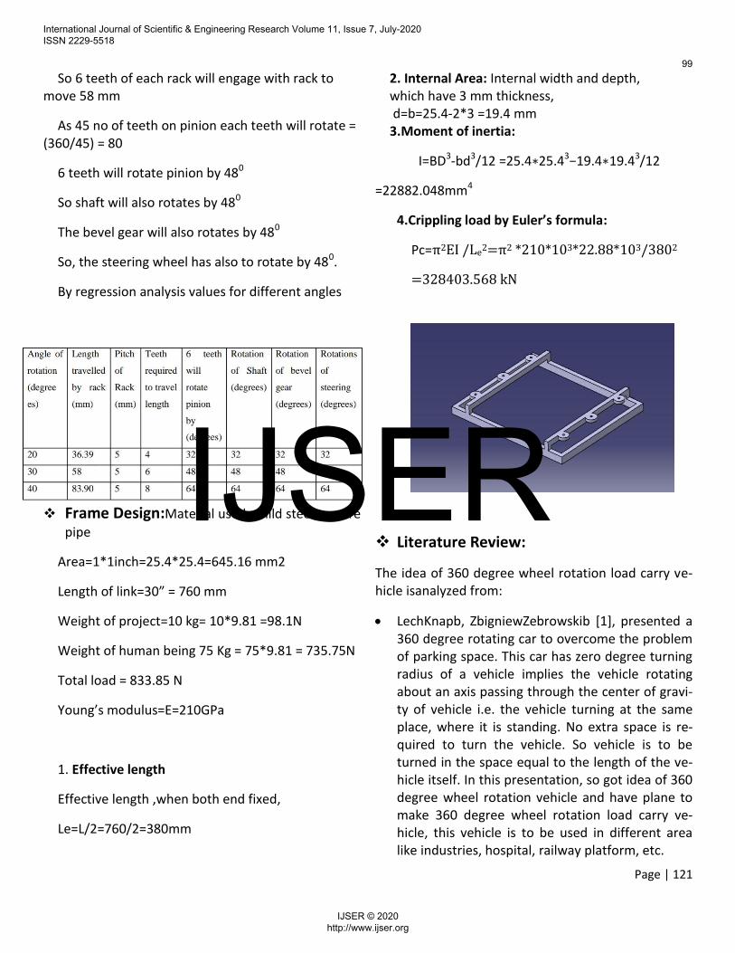
Frame Design:Material used –mild steel, square
pipe
Area=1*1inch=25.4*25.4=645.16 mm2
Length of link=30” = 760 mm
Weight of project=10 kg= 10*9.81 =98.1N
Weight of human being 75 Kg = 75*9.81 = 735.75N
Total load = 833.85 N
Young’s modulus=E=210GPa
1. Effective length
Effective length ,when both end fixed,
Le=L/2=760/2=380mm
2. Internal Area: Internal width and depth, which have 3 mm thickness, d=b=25.4-2*3 =19.4 mm 3.Moment of inertia:
I=BD3-bd3/12 =25.4∗25.43−19.4∗19.43/12
=22882.048mm4
4.Crippling load by Euler’s formula:
Pc=π2EI /Le2=π2 *210*103*22.88*103/3802
=328403.568 kN
Literature Review:
The idea of 360 degree wheel rotation load carry ve-hicle isanalyzed from:
LechKnapb, ZbigniewZebrowskib [1], presented a 360 degree rotating car to overcome the problem of parking space. This car has zero degree turning radius of a vehicle implies the vehicle rotating about an axis passing through the center of gravi-ty of vehicle i.e. the vehicle turning at the same place, where it is standing. No extra space is re-quired to turn the vehicle. So vehicle is to be turned in the space equal to the length of the ve-hicle itself. In this presentation, so got idea of 360 degree wheel rotation vehicle and have plane to make 360 degree wheel rotation load carry ve-hicle, this vehicle is to be used in different area like industries, hospital, railway platform, etc.
International Journal of Scientific & Engineering Research Volume 11, Issue 7, July-2020 ISSN 2229-5518
99
IJSER © 2020 http://www.ijser.org
IJSER
Page | 122
Prof.Avhad N.V. and Prof.Bhane A.B. [2],presented a 360 degree rotating vehicle to overcome the problem of parking space. This project is about design of 360 degree rotating car to move in all direction. This design provides bet-ter comfort and also saves the time of customers, that’s why it is also the reliable for the customer. As it is alsobattery operated car thus no fuel is re-quired. Hence it is economical to the environ-ment. This also reduces the cost of the car, and al-so got idea to use battery to operate this vehicle.
DilipChoudhari, et al. [3], presented a four wheel steering system for a car. In four wheel steering the rear wheels turn with the front wheels thus increasing the efficiency of the vehicle. The direc-tion of steering the rear wheels relative to the front wheels depends on the operating condi-tions. At low speed wheel movement is pro-nounced, so that rear wheels are steered in the opposite direction to that of front wheels with the use of DC motor to turn left and right. In this presentation, the use of DC motor is to rotate the wheels 90 degree left and 90 degree right from original position.
Er. Amitesh Kumar, et al. [4], presented zero turn four wheel steering system, the various functions of the steering wheel are, to control the angular motion the wheels, direction of motion of the ve-hicle, to provide directional stability of the vehicle while going straight ahead, to facilitate straight ahead condition of the vehicle after completing a turn, the road irregularities must be damped to the maximum possible extent. This project the use of steering is to rotate front wheels.
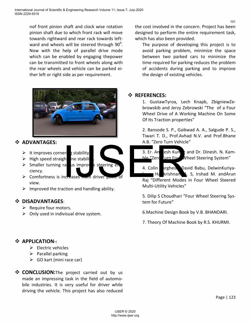
WORKING:90 degree steering mechanism basi-
cally helps to reduce the space required for a per-son to steer his vehicle. Our project of Fabrication of modified steering and drive mechanism for turning wheels through 90 degree in parallel park-ing, is a combination of four wheels steering for
90°turning. 90°steering mechanism is especially designed to decrease turning radius for parking purposes in confined spaces. For our project we are using rack and pinions, battery, bevel gears and other essential linkages .
Steering mechanism : For steering of our ve-hicle we are using a special set of rack and pi-nions joined with two sets of steering arms L1, L2, L3 and L4 attached to the wheels on each sides of vehicle i.e. front and rear side.For steering of the vehicle, the steering wheel Swill be connected through a steering shaft to steering bevel gears DS, and the shaft from DS will connect the two pinions P1 and P2.whensteering wheel is rotated in clock wise direction, the motion is transferred to the front pinion shaftwhich rotates pinion in clock wise direction due to which rack will slide to-wards left side and wheels will turn towards right side. Now the thickness of the pinions are sufficient to compensate the forward movement of rack.
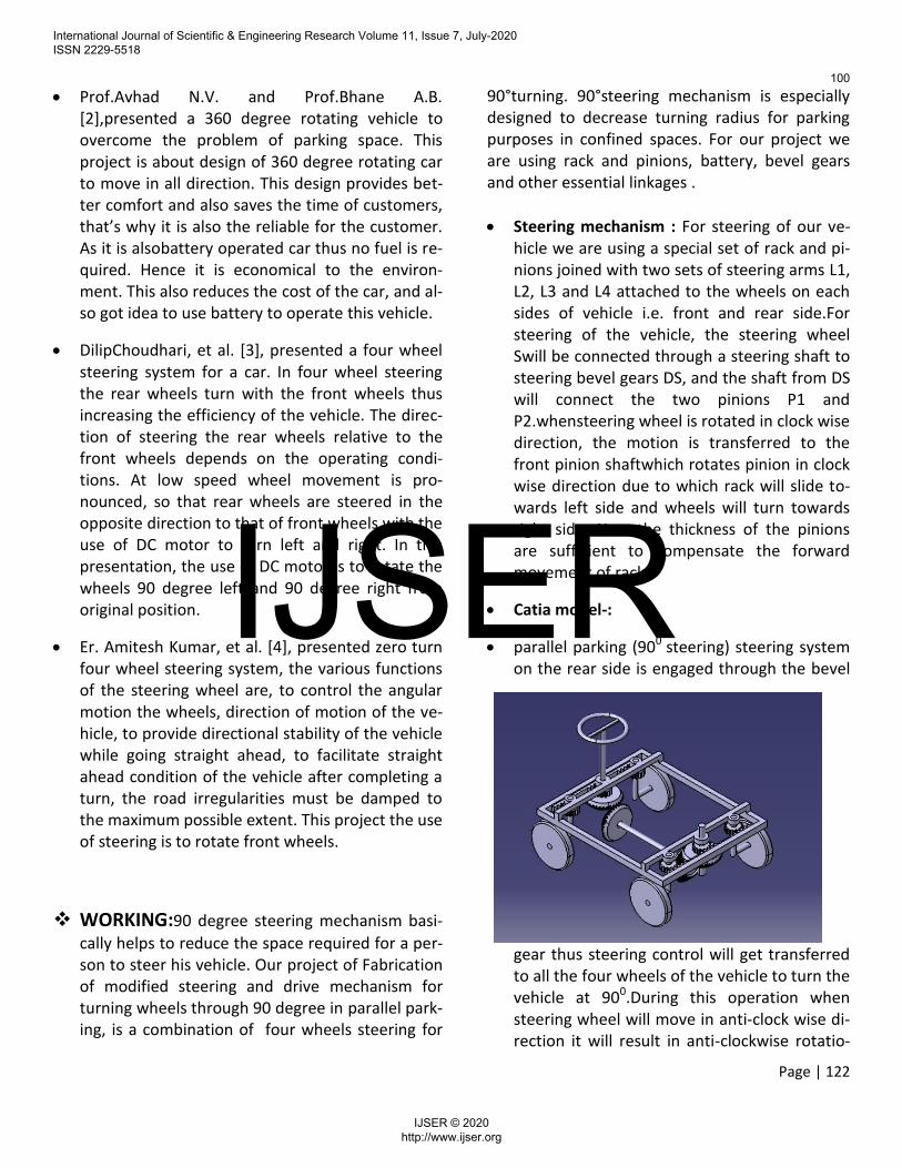
Catia model-:
parallel parking (900 steering) steering system on the rear side is engaged through the bevel
gear thus steering control will get transferred to all the four wheels of the vehicle to turn the vehicle at 900.During this operation when steering wheel will move in anti-clock wise di-rection it will result in anti-clockwise rotatio-
International Journal of Scientific & Engineering Research Volume 11, Issue 7, July-2020 ISSN 2229-5518
100
IJSER © 2020 http://www.ijser.org
IJSER
Page | 123
nof front pinion shaft and clock wise rotation pinion shaft due to which front rack will move towards rightward and rear rack towards left-ward and wheels will be steered through 900. Now with the help of parallel drive mode which can be enabled by engaging thepower can be transmitted to front wheels along with the rear wheels and vehicle can be parked ei-ther left or right side as per requirement.
ADVANTAGES:
It improves cornering stability. High speed straight line stability. Smaller turning radius improves steering effi-
ciency. Comfortness is increases from driver point of
view. Improved the traction and handling ability.
DISADVANTAGES:
Require four motors. Only used in indivisual drive system.
APPLICATION-:
Electric vehicles Parallel parking GO kart (mini race car)
CONCLUSION:The project carried out by us
made an impressing task in the field of automo-bile industries. It is very useful for driver while driving the vehicle. This project has also reduced
the cost involved in the concern. Project has been designed to perform the entire requirement task, which has also been provided.
The purpose of developing this project is to avoid parking problem, minimize the space between two parked cars to minimize the time required for parking reduces the problem of accidents during parking and to improve the design of existing vehicles.
REFERENCES: 1. GustawTyroa, Lech Knapb, ZbigniewZe-browskib and Jerzy Zebrowski “The of a Four Wheel Drive of A Working Machine On Some Of Its Traction properties”
2. Bansode S. P., Gaikwad A. A., Salgude P. S., Tiwari T. D., Prof.Avhad N.V. and Prof.Bhane A.B. “Zero Turn Vehicle”
3. Er. Amitesh Kumar and Dr. Dinesh. N. Kam-ble “Zero Turn Four Wheel Steering System”
4. Colin Varghese, David Babu, DelwinKuriya-kose, Harikrishnan. A. S, Irshad M. andArun Raj “Different Modes in Four Wheel Steered Multi-Utility Vehicles”
5. Dilip S Choudhari “Four Wheel Steering Sys-tem for Future”
6.Machine Design Book by V.B. BHANDARI.
7. Theory Of Machine Book by R.S. KHURMI.
International Journal of Scientific & Engineering Research Volume 11, Issue 7, July-2020 ISSN 2229-5518
101
IJSER © 2020 http://www.ijser.org
IJSER