Embed Size (px)
Citation preview
The Pennsylvania State University
The Graduate School
College of Engineering
DESIGN AND EXPERIMENTAL TESTING OF A BATTERY BALANCING SYSTEM
FOR LEAD-ACID BATTERIES
A Thesis in
Mechanical Engineering
by
Christopher M. Melville
2013 Christopher M. Melville
Submitted in Partial Fulfillment
of the Requirements
for the Degree of
Master of Science
August 2013
The thesis of Christopher M. Melville was reviewed and approved* by the following:
Christopher D. Rahn
Professor of Mechanical Engineering
Thesis Advisor
Eric R. Marsh
Professor of Mechanical Engineering
Karen A Thole
Professor of Mechanical Engineering
Head of the Department of Mechanical Engineering and Nuclear Engineering
*Signatures are on file in the Graduate School
iii
ABSTRACT
Lead-acid batteries are ubiquitous, comprising the most popular rechargeable battery
chemistry, widely used in stationary, EV, and HEV applications. Valve-regulated lead-acid
batteries (VRLAs) are particularly popular for a variety of characteristics including reduction of
spills and dangerous fumes, prolonged operating life and efficiency due to features such as
immobilized electrolyte and catalytic recombination of evolved hydrogen and oxygen, vibration
resistance, and resistance to lead dendrite formation. While these benefits confer a substantial
advantage to VRLAs, they are still susceptible to manufacturing flaws, progressive degradation
and user abuse. Many batteries, particularly large strings with high power and frequent cycling
requirements, have a battery management system (BMS) to monitor and protect against
overcharge, over discharge, excessive current rates, extreme temperatures, cell imbalance and
other safety factors dependent on the battery chemistry. In this thesis, a battery balancing system
is developed to demonstrate the lifetime battery benefits of maintaining cell balance. This thesis
demonstrates that the developed cell switching system (CSS) can bring the cells of a battery into
SOC balance and hold them there using an algorithm designed to charge the most unbalanced
cells first.
iv
TABLE OF CONTENTS
List of Figures .......................................................................................................................... v
Acknowledgements .................................................................................................................. vi
Chapter 1 Introduction ............................................................................................................. 1
VRLA Degradation Modes and Battery Management ..................................................... 2 Battery Management Architecture ................................................................................... 6
Chapter 2 Cell Switching System Design and Experimental Procedure .................................. 8
Chapter 3 Results and Discussion ............................................................................................ 12
Chapter 4 Conclusions and Future Work ................................................................................. 18
Appendix A The Cell Switching System Hardware and Software ......................................... 20
Hardware Design and Selection ........................................................................................ 20 Software Design ................................................................................................................ 22
Appendix B Circuit Diagrams ................................................................................................ 25
Bibliography ............................................................................................................................ 34
v
LIST OF FIGURES
Figure 1. VRLA battery configuration: cells are sealed and connected with current
collectors [1]. ................................................................................................................... 1
Figure 2. Simulation of two cells in series with different resistances [14]. ............................. 4
Figure 3. Simulation of two cells with different capacities [14]. ............................................. 5
Figure 4. Flowchart of CSS operating procedure. ................................................................... 10
Figure 5. View of the CSS. ...................................................................................................... 11
Figure 6. Chamber voltages (3-6) versus time under CSS balancing (14 hour test). ............... 12
Figure 7. Chamber voltages (3-6) versus time under CSS balancing. .................................... 13
Figure 8. Current into and out of cells 3-6, corresponding to Figure 7. ................................... 13
Figure 9. Chamber voltages (3-6) versus time under CSS balancing. ..................................... 14
Figure 10. Chamber Voltages (3-6) versus time under CSS balancing (steady state after
124 hours). ....................................................................................................................... 14
Figure 11. Chamber voltages (3-6) versus time under CSS balancing (steady state after
144 hours) ........................................................................................................................ 15
Figure 12. Chamber voltages (3-6) versus time under CSS balancing (steady state after
244 hours) ........................................................................................................................ 15
Figure 13. Solenoid switching logic. ....................................................................................... 23
Figure 14. Picture of the voltage and current sensing PCB [1]. ............................................... 25
Figure 15. Voltage and current sensing PCB drawing [1]. ...................................................... 26
Figure 16. High level view of PBTM [1]. ................................................................................ 27
Figure 17. Diagram of circuits on PBTM PCB [1]. ................................................................. 28
Figure 18. CSS switching hardware: relays, fuses, opto-isolators and transistors. .................. 29
Figure 19. CSS switching hardware: relays, fuses and relay wiring. ....................................... 29
Figure 20. CSS switching hardware: power transmission wiring of relays. ............................ 30
Figure 21. CSS switching hardware: dSpace ribbon cable, opto-isolators and transistors. ..... 30
Figure 22. Proposed CSS PCB. ................................................................................................ 31

vi
Figure 23. High-level view of the PBTM and CSS. ................................................................ 32
Figure 24. CSS Circuit Diagram. ............................................................................................. 33
vii
ACKNOWLEDGEMENTS
There are many people to whom I owe my gratitude and respect, too many to entirely
enumerate here. First and foremost I would like to thank Dr. Christopher Rahn for inviting me to
work on this project and subsequently obtain my master’s degree. He has been patient with me,
monitoring my progress from enough of a distance so as not to be restrictive while not being so
distant as to seem absent. Next I would like to thank my wife Donelle for her seemingly never
ending patience while I struggled with the challenges and milestones of getting a master’s degree;
I could not have done it without her help and support. I would like to thank my parents, Martin
and Judy, for making me who I am today, all my curiosity and drive were learned while I was
small and I certainly wouldn’t be where I am now without the sense of wonderment they instilled
in me. Similarly I would like to thank my grandparents, John and Shirley Dunkelberger, for
helping me to be inquisitive and strong and methodical and persevering; our friendship has been
extremely rewarding and meaningful to me. I would also like to thank Ying Shi for helping me
become familiar with the Mechantronics Research Laboratory equipment, both hardware and
software, the many hours of seemingly fruitless troubleshooting we had to do to keep things
running smoothly, and the opportunity to learn more about China and what life is like there. I am
equally indebted to Christopher Ferone for the excellent preceding work he did designing,
fabricating and documenting the hardware and software I had the pleasure of using in the
Mechatronics Research Laboratory. Finally I would like to thank the many friends and supporters
I have found in the Mechanical and Nuclear Engineering department: for all the lunches and
parties and hikes and words shared I would like to especially thank Bob Swope, Ben Rittenhouse,
Alex Dunbar, Michael Gouge, Max Ripepi, Andrew Barnett, Erick Froede, Taylor Blythe, and
anyone who ever joined us for lunch and offered an opinion.

1
Chapter 1
Introduction
Batteries are becoming more and more important as part of the solution to the energy
problem the world faces. Although lead-acid is the oldest rechargeable battery chemistry it still
remains popular for a variety of reasons including cost, available power, efficiency, previous
development and recycling infrastructure [2] [3]. Increasingly popular are valve-regulated lead-
acid batteries (VRLAs), characterized by immobilized electrolyte and an internal oxygen cycle
[4]. These batteries are effectively sealed, although they do have a pressure relief valve for
extensive gassing which is where they get the name “valve-regulated.” There are several benefits
to VRLAs over traditional flooded cell lead-acid batteries: acid spills are no longer possible; acid
fumes cannot escape the battery; explosive hydrogen cannot escape the battery and is catalytically
recombined with the evolved oxygen, preventing water loss; and in gel and absorbent glass-mat
(AGM) VRLAs the electrolyte is virtually immobile so electrolyte stratification is greatly reduced
[5] [4] [6]. The development of glass fibers in the micrometer range that could be formed into
Figure 1. VRLA battery configuration: cells are sealed and connected with current collectors [1].

2
mats and wetted with sulfuric acid has lead to AGM VRLAs that were not susceptible to lead
dendrites, had better hydrogen-oxygen recombination due to better gas transport, and could keep
the active materials in compression [4]. In spite of the myriad advantages of VRLAs they are still
susceptible to failure; much research has been done to enumerate and prevent these failure modes.
VRLA Degradation Modes and Battery Management
Battery failures can be roughly broken into two categories: catastrophic failures and
progressive failures. Catastrophic failures such as plate short circuits, loose terminals,
undercharging, overcharging, low electrolyte level, entry of harmful species and physical damage
such as broken containers and covers that lead to the immediate cessation of battery usage [7].
Progressive failures follow from the general use and not necessarily abuse of a battery and
include corrosion of the grid, irreversible sulfation, plate shedding, active mass degradation, cell
dehydration, and electrolyte stratification [6]. These failures are related to composition of grids,
plate thickness, composition of electrolyte, storage time, depth of discharge, current density of
discharge and recharge, degree of overcharge, temperature and uniformity of electrolyte
concentration [7]. Some of these failure modes can be remedied relatively easily, provided action
is taken before permanent damage is done, e.g. electrolyte stratification can be solved in a flooded
battery with the occasional heavy overcharge to mix the electrolyte through gassing, and
dehydration can be solved in flooded batteries simply by adding more water [4] [6]. There are a
variety of ways manufactures and users of batteries try to keep them in good health as long as
possible.
Battery state of charge (SOC) and state of health (SOH) are used as parameters to
determine when a battery is fully charged, what its available capacity is at any given time, and
how close to the end of life condition the battery is. More strictly SOC is ‘the ratio between the
3
difference of the rated capacity and the net amount of charge discharged from a battery since the
last full SOC on the one hand, and the rated capacity on the other hand’ [8]. It is accepted that for
lead-acid batteries open circuit voltage (OCV) is an acceptable surrogate for SOC [5]. There are
several methods to keep track of a battery’s SOC. Some of the more popular are: direct
measurement of OCV – which generally precludes a dynamic environment, book-keeping or
current counting which is susceptible to error over time, and adaptive methods which fuse OCV,
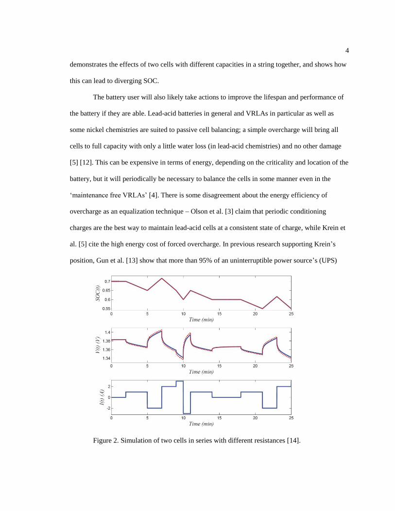
current counting and modeling to arrive at the SOC [10]. The impetus to track SOC is to
accurately predict when a battery powered device will run out of power and need to be recharged,
thus preventing overcharging and over discharging. Additionally, the ability to monitor the SOC
of individual cells in a string can prevent damage to individual cells that could incapacitate the
whole string. Figure 2 shows how internal resistance complicates dynamic SOC determination.
To improve battery and cell life, cells should be maintained at as close to the same SOC as
possible.
State of health is a more complex concept which monitors the degradation of the battery
over time. The primary way that SOH is determined is by comparing the total capacity of the
battery under consideration to the capacity of a new battery, ‘taking into account such factors as
charge acceptance, internal resistance, voltage, and self-discharge rate’ [10].
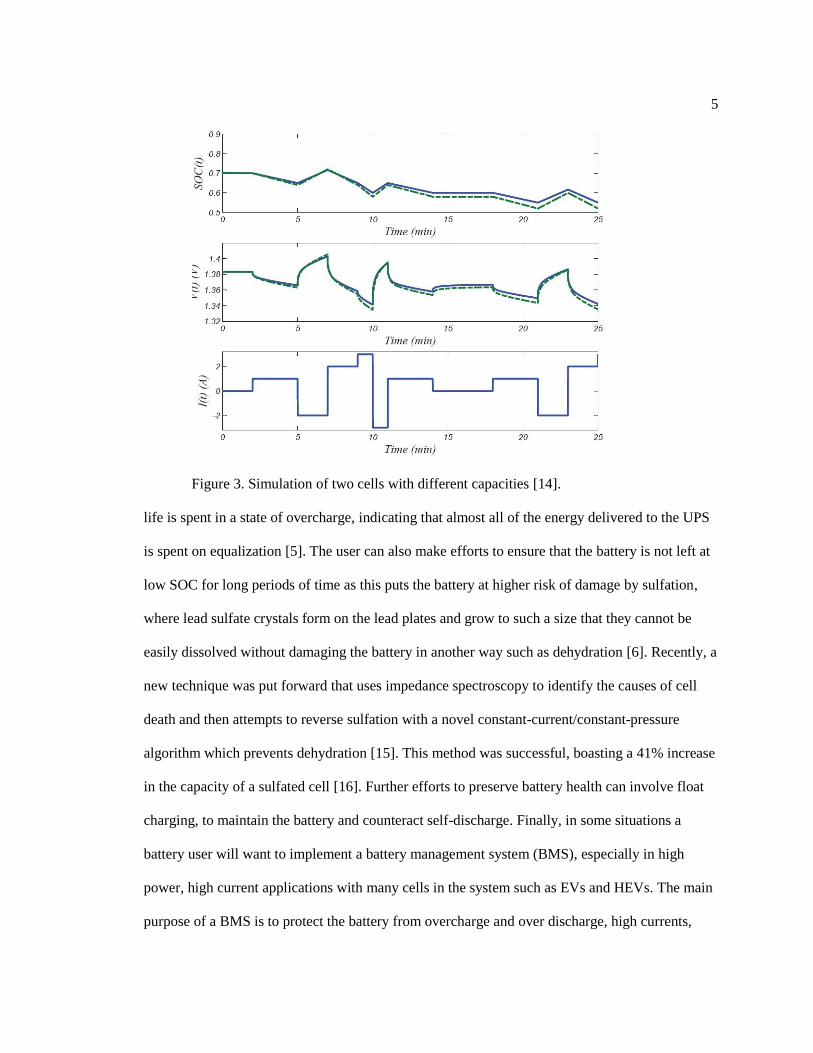
To improve lifespan, manufacturers take pains to ensure that all cells of a battery are as
similar as possible to each other in order to prevent cell imbalance. Generally, cell imbalance is
when the SOC of cells in a string are mismatched either due to inconsistent capacities or uneven
initial SOC, resulting in either ‘degraded pack performance relative to the weakest cell or the
abuse of the weak cell by the operation of the rest of the pack’ [3]. Since no two cells are exactly
identical due to ‘differences in SOC, self-discharge rate, capacity, impedance, and temperature
characteristics’ SOC divergence is a distinct possibility within a string of cells [11]. Figure 3
4
demonstrates the effects of two cells with different capacities in a string together, and shows how
this can lead to diverging SOC.
The battery user will also likely take actions to improve the lifespan and performance of
the battery if they are able. Lead-acid batteries in general and VRLAs in particular as well as
some nickel chemistries are suited to passive cell balancing; a simple overcharge will bring all
cells to full capacity with only a little water loss (in lead-acid chemistries) and no other damage
[5] [12]. This can be expensive in terms of energy, depending on the criticality and location of the
battery, but it will periodically be necessary to balance the cells in some manner even in the
‘maintenance free VRLAs’ [4]. There is some disagreement about the energy efficiency of
overcharge as an equalization technique – Olson et al. [3] claim that periodic conditioning
charges are the best way to maintain lead-acid cells at a consistent state of charge, while Krein et
al. [5] cite the high energy cost of forced overcharge. In previous research supporting Krein’s
position, Gun et al. [13] show that more than 95% of an uninterruptible power source’s (UPS)
Figure 2. Simulation of two cells in series with different resistances [14].
5
Figure 3. Simulation of two cells with different capacities [14].
life is spent in a state of overcharge, indicating that almost all of the energy delivered to the UPS
is spent on equalization [5]. The user can also make efforts to ensure that the battery is not left at
low SOC for long periods of time as this puts the battery at higher risk of damage by sulfation,
where lead sulfate crystals form on the lead plates and grow to such a size that they cannot be
easily dissolved without damaging the battery in another way such as dehydration [6]. Recently, a
new technique was put forward that uses impedance spectroscopy to identify the causes of cell
death and then attempts to reverse sulfation with a novel constant-current/constant-pressure
algorithm which prevents dehydration [15]. This method was successful, boasting a 41% increase
in the capacity of a sulfated cell [16]. Further efforts to preserve battery health can involve float
charging, to maintain the battery and counteract self-discharge. Finally, in some situations a
battery user will want to implement a battery management system (BMS), especially in high
power, high current applications with many cells in the system such as EVs and HEVs. The main
purpose of a BMS is to protect the battery from overcharge and over discharge, high currents,
6
high temperatures, cell imbalance and to address any other applicable safety concerns [17] [14].
Kuhn et al. cite the economic benefits of active balancing as generating a cost savings of at least
30% on maintenance – and potentially higher savings depending on various factors – motivating
the usefulness of BMS technology [18].
Battery Management Architecture
Battery management systems perform active or passive cell balancing. In passive
balancing, current is directed around cells which are ‘full’ – at 100% SOC – and shunted through
resistors. This method is very cheap to implement but not very effective at balancing batteries
with substantial variation in SOC, as well as being wasteful of energy [17]. Ostensibly, one of the
main purposes of a BMS is to prevent the loss of energy that could be stored, so while this
method is good for protecting the health and lifespan of the battery it may be undesirable
depending on the application. Some authors also consider conditioning charges to be a form of
passive balancing, since they serve that purpose; this is also not particularly energy efficient, as
discussed previously [18] [3]. Typically passive balancers only function during the charge cycle.
Sorted by circuit topology there are three types of active balancers: the shunting method,
the shuttling method, and the energy converter method [17]. The shunting method is similar to the
passive shunting method described above but instead of changing current flow immediately upon
reaching a certain voltage for a given cell the current is proportionally shunted away through
resistors [17]. The shuttling method involves capacitive or inductive charge shuttling from cells
with high SOC to cells with low SOC, and can be much more efficient for batteries with frequent
charge-discharge cycling [17] [11]. The energy converter method is defined by Cao et al. as
‘isolated converters’ where ‘the input and output side of the converters have isolated grounds’
[17]. However, the power wasted in standby may be greater for active balancing than for passive
7
balancing due to the need to power the control hardware [9]. The additional hardware and non-
recurring engineering costs of an active balancer make it significantly more expensive, although
the promised energy and battery life savings may outweigh the costs [11].
For this project a switching system will be added to the programmable battery testing
machine (PBTM) developed by Ferone in [1] for the purpose of testing the effects of balancing on
battery life. Krein et al. [5] note that a hole exists in the literature: no study so far has confirmed
the battery life benefits of external equalization methods. To date they all start with large,
prearranged cell mismatches, which is unrealistic and not representative of what an actual
balancing circuit would hope to achieve. This research aims to enable the Mechatronics Research
Laboratory at The Pennsylvania State University to fill that void.
8
Chapter 2
Cell Switching System Design and Experimental Procedure
The cell switching system (CSS) was designed to allow the PBTM to automatically
switch the LVC5050 mass charger between cells of an AGM VRLA battery. The battery has been
specially outfitted with contacts going into the current collectors of cells 2-5 (refer to Figure 1),
as well as pressure transducers for measuring the pressure in each cell. The ‘cells’ actually consist
of 18 parallel lead-acid voltaic cells, but since they are all the same voltage and not differentiated
in this discussion they will be referred to as cells [1]. The CSS switching hardware consists of 12
solenoids, six transistors to switch the solenoids, and six opto-isolators to isolate the dSpace data
acquisition ground from the noise of the solenoids as well as to prevent large currents from
burning out the sensitive DAQ channels. Cells 2-5 are connected to two solenoids each, staggered
so that, for example, when the cell two solenoids are turned on cell two is connected, and when
the cell three solenoids are turned on cell three is connected, but each cell makes only one
connection to the CSS. The highest and lowest voltage-potential connectors of the battery are
only connected to one solenoid, because they do not have a cell above or below them
respectively. The CSS has a 12 V power supply to supply power to the solenoids, transistors,
opto-isolators and cooling fans. There is also a sensing circuit, cannibalized from work previously
done in the laboratory, that measures the voltage of a second leg of the mass charger, and a
current sensor. This PCB has its own voltage rectifier, taking 120 V power down to 5 V, and +/-
12 V; this is because the instrumentation op-amps require a particularly clean DC power supply.
The design of the CSS was a fairly linear process with only a few iterative changes
necessary. The most notable design change was an adjustment from transistor switches to
solenoid switches. This was done because the dSpace DAQ was running out of available channels
for sensing, mass charger control, and solenoid switching. To use transistors, which can only flow

9
current one direction, would have required twice as many TTL channels. After this change
solenoids were selected that operated on the voltage of the chosen fans, and that could withstand
the required current. A prototype was mocked up on a breadboard; it was confirmed that manual
cell switching was possible, that no current was flowing between cells of the battery, and that the
staggered solenoid connection functioned in the desired manner. Next the prototype was
transferred to hobbyist’s pin-board. It was confirmed that the selected cell voltage was measured
at the terminals of the CSS, and that the circuit still functioned as desired. Finally, the fans,
sensing PCB, shielded banana-connectors, fuse box, CSS hardware board and 12V power supply
were all assembled into a rack-mount enclosure.
Modifications were made to the PBTM control code. This code is written in the Matlab
data-flow GUI called SimuLink, compiled into an executable real-time interface (RTI) and loaded
onto the dSpace DAQ. Real-time adjustments can be made through the ControlDesk GUI
experiment manager; this is also the software that compiles the data into files for processing at a
later date. The primary modifications to the control code were: creating the subsystem to select
which cell to charge or discharge, including grabbing the cell number and voltage; creating a
subsystem to control the mass charger voltage matching, connection, current flowing and
disconnection; the logic to send TTL signals to switch the CSS solenoids was added to an
existing subsystem; switches were also added throughout the program to allow automatic
balancing to be turned on and off while retaining program functionality in manual mode. An
additional subsystem was added to control a second leg of the LVC5050, but this block is not
currently in use. For each variable that could conceivably need to be adjusted in real-time the
ControlDesk GUI had to be modified. The ControlDesk GUI was also modified to reflect which
cell the CSS was connected to, so that the user could ascertain the state of the program.
Specifically, sometimes the code would select a cell, but then the algorithm would change which
cell had been selected before the cell voltage could be passed on; this made it so the code to

10
connect the mass charger to the battery would get stuck trying to match the wrong command
voltage to a given cell voltage. To counteract this, a reset button was added to the ControlDesk
GUI to send the connection code back to the start point and re-select a cell number and voltage.
In this study the CSS was connected to cells 3-6 of a 75 Ah AGM VRLA battery. The
actual capacity of the battery had fallen to approximately 70 Ah [1]. The CSS selected cells based
on which cell had the maximum error from a selected operating point, chosen as approximately
the average voltage of the four cells, 2.080 V in this case. The CSS then matched the voltage of
the mass charger with the voltage of the cell to within 5% before connecting the cell and the mass
charger. The cell was then subjected to current of 3 A for 2-5 s to bring the cell voltage closer to
the average. There was a half-second delay between cells to allow the cell to return to something
closer to OCV, as well as for safety to ensure that multiple cells were never connected to the
PBTM at the same time, which could allow unwanted current flow.
Figure 4. Flowchart of CSS operating procedure.

11
Due to the dynamics of the feedback controller in the PBTM the current did not jump as
a step function but had some ramp rate. As the test progressed the time that the current was
flowing decreased to reduce the cell voltage jump due to the cells internal resistance. The test was
stopped when the voltage of the cells stayed within .5% of the operating point, which amount to
approximately 10 mV. The error from this operating point was chosen such that the maximum
variation from the operating point was 5 mV and the maximum variation between any two cells
would not exceed 10 mV; when using voltage for SOC matching voltage differences must be kept
small, in the 10-15 mV range [5].
Figure 5. View of the CSS.

12
Chapter 3
Results and Discussion
The CSS and PBTM perform their function and bring the cells of the battery into equilibrium
with similar voltages. Without knowing the capacities of the cells a priori it cannot be said how
well balanced the cells actually are. The experimental results for cells 3-6 are presented in
Figure 6 - Figure 12 and discussed in the following paragraphs.
Figure 6. Chamber voltages (3-6) versus time under CSS balancing (14 hour test).

13
Figure 7. Chamber voltages (3-6) versus time under CSS balancing.
Figure 8. Current into and out of cells 3-6, corresponding to Figure 7.

14
Figure 9. Chamber voltages (3-6) versus time under CSS balancing.
Figure 10. Chamber Voltages (3-6) versus time under CSS balancing (steady state after
124 hours).

15
Figure 11. Chamber voltages (3-6) versus time under CSS balancing (steady state after 144 hours)
Figure 12. Chamber voltages (3-6) versus time under CSS balancing (steady state after 244 hours)

16
In Figure 6 it can be seen that the cells which have the largest voltage differences are
brought to the same voltage and held there. Also visible in Figure 6, shortly after the one hour
mark, one can see a time where the cell voltages are relaxing because the program had gotten
stuck – it had selected a cell voltage not matching the cell it was trying to connect to so the mass
charger voltage didn’t come within 5% of the cell voltage which would initiate current transfer;
this problem was fixed by improving the feedback control and adding a reset button for manual
reset. Figure 7 shows a very zoomed-in view of the test around hour five, showing discharging of
cell 5, and charging of cells 3 and 6. Corresponding to Figure 7, Figure 8 shows the current into
and out of cells 3-6; for example at minute 306 of the test cell 6 is being charged, followed by cell
3 being charged, then cell 6 is charged two more times before cell 5 is discharged. Cell 4 is not
being discharged because it is not the cell with the maximum error from the operating point. In
Figure 9 one can see, in the voltage of cell 3, that the algorithm would charge the cell and then,
before the OCV had relaxed, the algorithm would again select the cell but for discharge this time.
This problem was fixed by shortening the amount of time that current was flowing, which
lowered the voltage jump enough so the behavior stopped. Figure 10, Figure 11, and Figure 12
show the CSS balancing at 124, 144 and 244 hours respectively. The main point of interest here is
to notice that the frequency of current flow is lessening, particularly compared to Figure 7,
although the change in charging between 144 and 244 hours is not noticeable.
The algorithm for balancing was exceptionally simple. For the purpose of studying the
lifetime effects of preserving a battery’s equilibrium this may be acceptable, but if there is interest
in experimenting with different balancing algorithms the current hardware may be inadequate.
The switching speeds of the current hardware are insufficient to emulate a PWM balancing
architecture, for example. It should be a fairly simple thing to replace the solenoids in the circuit
with IGBTs. Another change that could influence the performance of the CSS is to improve the
17
performance of the control algorithm, so the current ramp rate would be faster. It would also be
beneficial to automate the end condition and the charge-time decrease.
The performance of the CSS as a battery balancer is adequate. While the cell voltages were
brought close to each other relatively quickly (5-6 hours, see
Figure 6 the actual SOC equilibrium is still not very close, as evidenced by the
rapidity with which the cell voltages begin to diverge after getting a shot of charge. It is
interesting to note that cells 4 and 5, which had smaller internal resistance and smaller voltage
spikes when current is flowing, approached and stayed at the operating point much faster than
cells with higher internal resistance, cells 3 and 6. While cells 4 and 5 stopped requiring current
relatively early, cells 3 and 6 continued to need current for a very long time – on the order of
several days.
It seems unlikely that this balancer would be very effective in practice if it takes over ten
days to balance 4 cells that initially are not terribly out of balance. The algorithm almost needs a
CV mode to finish the charge to the operating point. As an example, to balance an Optima G34
Yellow Top within 5% SOC the charge difference between cells could still be as high as 2.5 A-h
[3]. At 3 A it would take nearly an hour of continuous charging to bring a cell to the operating
point plus the CV finishing time, and the CSS is not nearly continuous. The current algorithm
does not have any architecture to allow it to change its behavior during a CC-CV charge cycle
either; it cannot be predicted how the program would act during such a cycle, although it seems
likely that it could cause potentially damaging cell overvoltage. It is possible that a newer battery
would balance fast enough for this balancer to be practical, and that it could maintain the battery
at a level of health where the BMS would still function acceptably.
18
Chapter 4
Conclusions and Future Work
In conclusion, the CSS allows the PBTM to be employed to balance four cells of an
AGM VRLA. While the CSS brought the cell voltages together relatively quickly it would take a
long time to bring the cells into SOC balance. Excessive runtime of the current architecture
makes it hard to judge the usefulness of the CSS. There are exciting possibilities for the
application of the CSS: the possibility to emulate, evaluate and quantify the potential cost savings
of varying BMS architectures. The use of IGBTs instead of solenoids would make the CSS
dramatically faster, which in turn would allow for the modeling and emulation of alternative
BMS architectures.
Future work includes experimenting with BMS architecture emulation, efficiency studies,
and the side by side comparison of actively balanced versus passively balanced or untended
batteries. Swapping the solenoids for IGBTs would drastically improve the ability of the CSS to
mimic other BMS architectures, since the current switching speeds of the CSS are below 40 Hz
and a typical PWM system operates above 100 Hz. Architecture emulation would involve
studying the previously documented behavior of BMSs, doing some system identification on the
CSS, and changing the cell selection code to approximate the charging and discharging behavior
of the selected BMSs. If no documentation is available for the behavior of certain BMS
architectures data may have to be generated as part of the investigation. Once the CSS can
sufficiently emulate a variety of BMSs, efficiency studies could be done to determine if the
anticipated power consumption of the balancing power electronics offsets the power saved by the
BMS. Because the researcher will know the current and voltage into and out of cells in the string
they will be able to determine, based on the models of the architecture they are testing, how much
energy is being saved. The energy consumption of the power electronics could be estimated based

19
on the power consumption of the components; while this might not be a terribly exact estimate,
no current research endeavors to estimate the in situ usefulness of BMSs. The selection of BMS
architectures could benefit from quantifiable evidence as to the efficiency of one system
compared to another. A side-by-side test is also an exciting application for the CSS. While there
is plenty of intuitive evidence to support the usefulness of BMSs, there is a dearth of quantifiable,
empirical evidence supporting battery management. To learn more about just how much a BMS
can improve the lifespan of a battery the CSS could be used to balance a battery undergoing some
pre-defined cycle on a separate mass charger while the CSS balances the cells of the battery. For
a control several batteries could be subjected to the same pre-defined cycle without the benefit of
the CSS to hold the cells in balance. This could shed light on both the reduced capital expenditure
resulting from longer battery lifespan, as well as potential efficiency gains that result from charge
shuttling, which could result in significantly lower energy costs over the life of a battery. While it
may seem counter-intuitive that the capital cost of the battery would be outweighed by the cost of
the energy cycled through the battery, over the life of said battery it is likely that the energy costs
are significantly higher.

20
Appendix A
The Cell Switching System Hardware and Software
The cell switching system was designed with several key functionalities in mind.
Foremost, it had to interface with the existing hardware and software. The PBTM consisted of a
dSpace control module for all DAQ, D/A, and A/D performed during the experiment, a series of
sensing circuits using instrumentation op-amps to measure current into and out of the battery as
well as cell voltages, a series of power electronics to switch the mass charger on and off as well
as add resistors to the circuit for more efficient charging and discharging, and a linear amplifier
for the mass charger. The CSS also needed to be able to switch between cells both automatically
and manually, for individual cell cycling as well as automatic balancing. The CSS needed to be
able to transmit the requisite current to satisfy the needs of automatic and manual cell balancing.
Finally there was the need for safety features such as fusing, shielding, and heat rejection.
Hardware Design and Selection
The primary purpose of the hardware was to enable automatic switching between cells
for charge and discharge. Solenoids were selected to do the switching for their current carrying
capacity. The solenoids are switched by transistors, which are switched through opto-isolators by
the dSpace controller. The opto-isolators are to ensure that the dSpace module is protected from
large voltages and currents. The inputs on the dSpace module are rated for tens of milliamps,
while the battery is capable of supplying hundreds of amps. Care was also taken to ensure that no
ground loops were formed between the dSpace module, the sensing PCB, the fan and relay power
source, and the mass charger.

21
Due to a lack of additional channels on the dSpace module a creative circuit was
designed whereby only one digital output was necessary to turn on two power solenoids to
connect the mass charger to only one cell at a time. Initially transistors were selected, but since
current can only flow through them one way it would have doubled the number of control outputs
from the dSpace module that were needed. In retrospect IGBTs would have been a better choice
as current can flow through them both ways and they have switching speeds on the order of
nanoseconds, but the researcher did not have that knowledge at the time the selection was made.
Hardware was cannibalized from the PBTM project for current sensing and mass charger
voltage sensing. The circuit was designed to generate its own low-ripple power supple but the
selected transformer was mismatched to the power requirements of the circuit and a power
resistor had to be added to draw down the voltage of the rectified power supply. Additional heat
rejection was also added, both to the existing sensing PCB and the cannibalized PCB in the form
of TIP-220 bolt-on heat sinks; linear voltage regulators kept burning up and wreaking havoc with
the instrumentation op-amps.
The cell switching relays are TE RTD34012F 16A 12V relays selected for their current
carrying capacity; the max operate/release time for this relay under load is 8 ms excluding bounce
[19]. This makes the maximum switching speed 62.5 Hz. The power relay in the PBTM which
switches between charge and discharge mode (shunting extra current through resistors to the load
the mass charger sees is smaller) has an operate /release time of 30 ms, excluding bounce [20].
The slew rate of the LVC5050 mass charger is >30 V/μs, but the dynamics of the feedback
control system make the current response much slower [21].
The power supply for the fans and relays was selected simply out of convenience; it was
the same unit used in the PBTM.
22
Software Design
The control software for the PBTM was modified so both the PBTM and the CSS could
be controlled by the dSpace module. The control software consists of a SimuLink model which is
built into an RTI and loaded onto the dSpace module. A ControlDesk GUI allows for assigned
variables within the model to be changed in real-time. The switching algorithm was designed to
maintain the cell voltages around an operating point near the cell average, eventually bringing
them into SOC equilibrium. Initially the software was designed to supply +/-3 A for 5 seconds,
but as the CSS approached the operating point the charging or discharging caused the cell voltage
to shoot far enough past the operating point that the algorithm would immediately reverse the
current direction through the cell which it had just been connected to. This effect was particularly
noticeable with cells that had lower internal resistance – the immediate cell voltage jump upon
mass charger connection/disconnection was slower, causing confusion for the switching
algorithm. To ameliorate this, the charge time was changed to 3 s, then to 2 s, but this
dramatically increases the equalization time. Ideally the hardware would be modified with
(IGBTs) putting the battery in parallel with shunt resistors for PWM charging, and the software
would be modified so that the charge/discharge switch was only done occasionally.
The main changes to the model from PBTM operation allow for the automated selection
of a cell, the matching of the mass charger voltage to the cell voltage, switching on relays to
connect the mass charger and the battery cell, the addition or removal of current, disconnecting
the mass charger and the battery, and selection of a new cell. Cell selection is done in a non-
graphical function within Simulink by taking the cell voltages and the operating point voltage and
determining which cell has the maximum error. That cell number and voltage is then passed to a
Simulink StateFlow state machine which neatly allows for the logical progression (match voltage,
connect, current on, disconnect) described above. The code to switch on the solenoids to connect

23
the mass charger to the battery is designed so that, barring a mechanical failure, there is no
possible way for multiple cells to be switched ‘on’ at any time (see Figure 13). Only when the
cell selector equals 1-6 – which comes from the error determining function – and the cell_ON
variable is HIGH – this comes from the StateFlow code – can the mass charger be connected to
the battery. The final substantial change to the PBTM control code was to add a sensing and
control subsystem to control the low voltage leg of the mass charger. Since this function was not
used that subsystem block remains unused.
Figure 13. Solenoid switching logic.
24
One of the tremendous advantages of having the switching algorithm coded instead of
hardwired is that, within the limits of the mass charger and the solenoid switching speed, the
PBTM and CSS can be used to emulate many different architectures. The actual circuit topology
is most similar to a single switched capacitor, but instead of a capacitor there is another mass
charger. This system is not a particularly efficient – all sunk current is dumped into resistors – but
that is not the main concern of the CSS, which is purely for laboratory testing.

25
Appendix B
Circuit Diagrams
Figure 14. Picture of the voltage and current sensing PCB [1].

26
Figure 15. Voltage and current sensing PCB drawing [1].
27
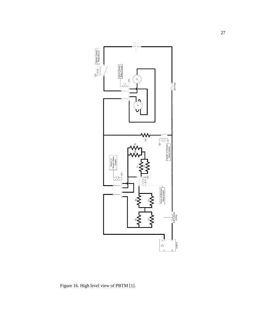
Figure 16. High level view of PBTM [1].
28
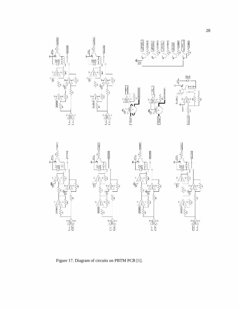
Figure 17. Diagram of circuits on PBTM PCB [1].

29
Figure 18. CSS switching hardware: relays, fuses, opto-isolators and transistors.
Figure 19. CSS switching hardware: relays, fuses and relay wiring.

30
Figure 20. CSS switching hardware: power transmission wiring of relays.
Figure 21. CSS switching hardware: dSpace ribbon cable, opto-isolators and transistors.
31
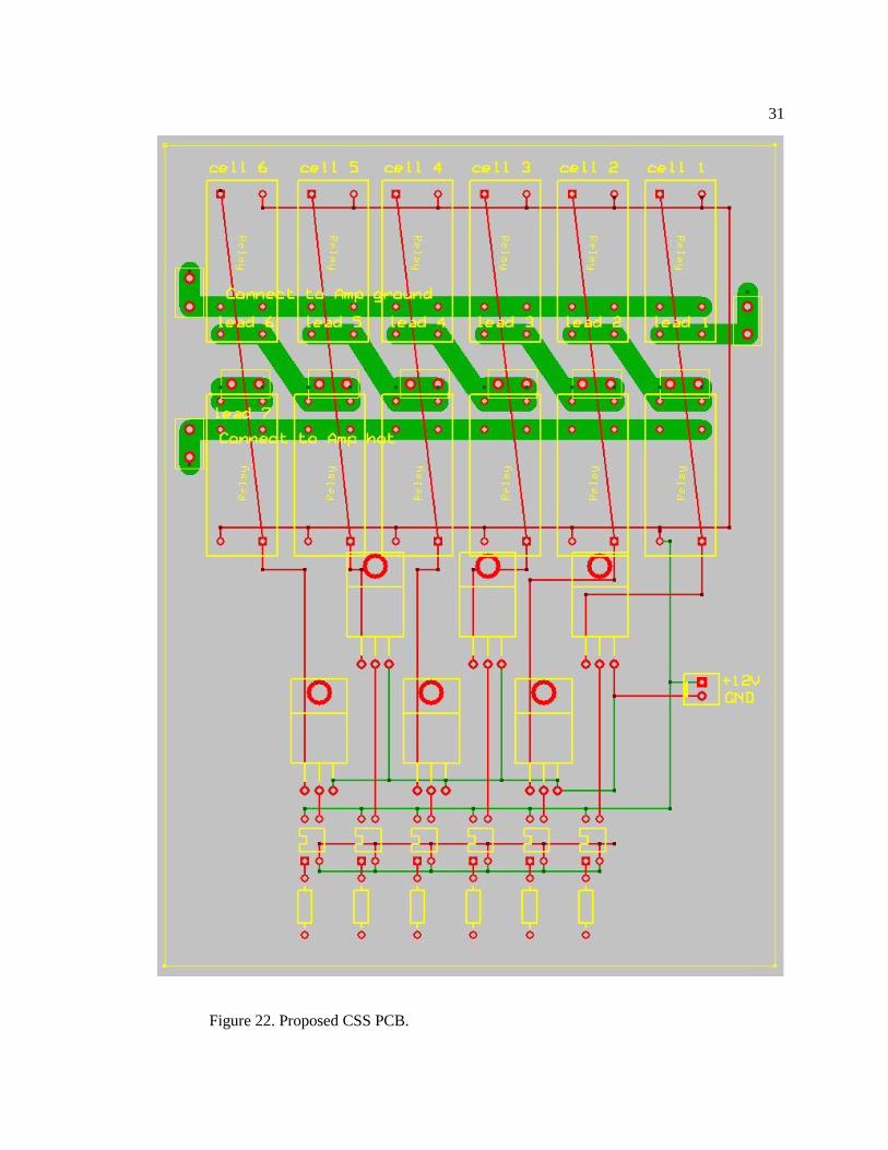
Figure 22. Proposed CSS PCB.

32
Figure 23. High-level view of the PBTM and CSS.

33
Figure 24. CSS Circuit Diagram.

34
Bibliography
1. Ferone, C.A., NONDESTRUCTIVE FORENSIC PATHOLOGY OF LEAD-ACID
BATTERIES, in College of Engineering. 2012, The Pennsylvania State University:
University Park, PA.
2. Buchmann, I. Can the Lead-Acid Battery Compete in Modern Times? Battery University
2010 [cited 2013 6/21/13].
3. Olson, J.B. and E.D. Sexton. Operation of lead-acid batteries for HEV applications. in
Battery Conference on Applications and Advances, 2000. The Fifteenth Annual. 2000.
IEEE.
4. Berndt, D. A look back at forty years of lead-acid-battery development; A survey
especially regarding stationary applications. in Telecommunications Conference, 2005.
INTELEC'05. Twenty-Seventh International. 2005. IEEE.
5. Krein, P.T., S. West, and C. Papenfuss. Equalization requirements for series VRLA
batteries. in Applications and Advances, 2001. The Sixteenth Annual Battery Conference
on. 2001. IEEE.
6. Bindner, H., et al., Lifetime modelling of lead acid batteries. 2005.
7. Culpin, B. and D. Rand, Failure modes of lead/acid batteries. Journal of power sources,
1991. 36(4): p. 415-438.
8. Piller, S., M. Perrin, and A. Jossen, Methods for state-of-charge determination and their
applications. Journal of power sources, 2001. 96(1): p. 113-120.
9. Munwaja, S., B. Tanboonjit, and N.H. Fuengwarodsakul. Development of cell balancing
algorithm for LiFePO< inf> 4</inf> battery in electric bicycles. in Electrical
Engineering/Electronics, Computer, Telecommunications and Information Technology
(ECTI-CON), 2012 9th International Conference on. 2012. IEEE.
10. Pop, V., et al., State-of-the-art of battery state-of-charge determination. Measurement
Science and Technology, 2005. 16(12): p. R93.
11. Wen, S., Cell balancing buys extra run time and battery life. Analog Applications, 2009.
12. Moore, S.W. and P.J. Schneider, A review of cell equalization methods for lithium ion
and lithium polymer battery systems. SAE Publication, 2001: p. 01-0959.
13. Gun, J.-P., et al. Increasing UPS battery life main failure modes, charging and
monitoring solutions. in Telecommunications Energy Conference, 1997. INTELEC 97.,
19th International. 1997. IEEE.
14. Rahn, C.D. and C.-Y. Wang, Battery systems engineering. 2012: Wiley.
15. Shi, Y., et al. Nondestructive forensic pathology of lead-acid batteries. in American
Control Conference (ACC), 2012. 2012. IEEE.
16. Shi, Y., C.A. Ferone, and C.D. Rahn, Identification and remediation of sulfation in lead-
acid batteries using cell voltage and pressure sensing. Journal of Power Sources, 2012.
17. Cao, J., N. Schofield, and A. Emadi. Battery balancing methods: A comprehensive
review. in Vehicle Power and Propulsion Conference, 2008. VPPC'08. IEEE. 2008.
IEEE.
18. Kuhn, B., R. Spée, and P.T. Krein. Lifetime Effects of Voltage and Voltage Imbalance on
VRLA Batteries in Cable TV Network Power. in Telecommunications Conference, 2005.
INTELEC'05. Twenty-Seventh International. 2005. IEEE.
19. TE-Connectivity, Power PCB Relay RT1. 2011, Tyco Electronics Corporation:
http://www.te.com/catalog/results/en/web?t=y&q=rtd34012F. p. 3.

35
20. Panasonic. HG Relays datasheet. 2012 [cited 2013 June 27]; Datasheet].
21. Techron, LVC5050 Power Supply Amplifier Technical Manual. 2002, AE Techron: 2507
Warren St. Elkhart IN 46516 U.S.A.