Embed Size (px)
Citation preview

8/10/2019 Design and Development of Shell and Tube Heat Exchanger for Harar Brewery Company Pasteurizer Application (…
http://slidepdf.com/reader/full/design-and-development-of-shell-and-tube-heat-exchanger-for-harar-brewery-company 1/11
Amer ican Journal of Engineer ing Research (AJER) 2014
w w w . a j e r . o r g Page 99
American Journal of Engineering Research (AJER)
e-ISSN : 2320-0847 p-ISSN : 2320-0936
Volume-03, Issue-10, pp-99-109
www.ajer.org
Research Paper Open Access
Design and Development of Shell and Tube Heat Exchanger for
Harar Brewery Company Pasteurizer Application (Mechanical
and Thermal Design)
Dawit Bogale Lecturer in School of Mechanical and Industrial Engineering Bahir Dar Institute of Technology,Bahir Dar, Ethiopia
ABSTRACT: A heat exchanger is a device that is used to transfer thermal energy (enthalpy) between two ormore fluids, between a solid surface and a fluid, or between solid particulates and a fluid, at differenttemperatures and in thermal contact [1] .From different types of heat exchangers the shell and tube heat
exchangers with straight tubes and single pass is to be under study. Here the redesign takes place because oftemperature fluctuation at the 9
th zone of the pasteurizer in the Harar Brewery Company. Thermal and
mechanical design is run in order to optimize the output temperature of the cold fluid at the last heat exchanger
in which it is sprayed on the beer ready for customer use. In thermal design part geometry optimization is donethrough trial and error. And for Mechanical design part the natural frequency& vortex shedding of differentcomponents of heat exchangers are investigated through governing equations of vibrations under dynamic fluid
with in tubes. Using computational fluid dynamics (CFD) the heat transfer of the two fluid is investigated using FEM simulation software’s Gambit 1.3 and Fluent 6.1 and the performance of the STHEx determined in termsof variables such as pressure, temperature, flow rate, energy input/output, mass flow rate and mass transfer ratethat are of particular interest in STHEx analysis.
KEYWORDS: Enthalpy, Gambit 2.4.6 and Fluent 6.1, Simulation, CFD, STHEx, Pasteurizer
I. INTRODUCTIONIn heat exchangers, there are usually no external heat and work interactions. Typical applications
involve heating or cooling of a fluid stream of concern and evaporation or condensation of single- ormulticomponent fluid streams. In other applications, the objective may be to recover or reject heat, or sterilize, pasteurize, fractionate, distill, concentrate, crystallize, or control a process fluid. In a few heat exchangers, the
fluids exchanging heat are in direct contact. In most heat exchangers, heat transfer between fluids takes place
through a separating wall or into and out of a wall in a transient manner. In many heat exchangers, the fluids areseparated by a heat transfer surface, and ideally they do not mix or leak [1].But because of vibration induced due
to the dynamics of the fluid in the tube there may be linkage in the baffle and the shell wall. The use of the baffles in heat exchangers is to enhance heat transfer through turbulence of the shell side flow and to reduce thevibration (Natural frequency) of the tube.
The STHEx under study for this paper is found in Harar Brewery Company at the 9th zone of the
pasteurizer. Here the pasteurizer works in engineering principle’s in order to make the bottles adopt for waterwith maximum temperature and that of minimum temperature. The detail of the working principle of machine isshown in Figure 1 below.
Here for the STHEx in Harar brewery company the two system fluids in which heat is going to beexchanged is water and steam(H2O in gas state). Steam with mass flow rate of 6000kg/hr enters at 160
0C shell
side in which a cool water at 250C enters the tube side and out at a designed temperature of 35.5 0C and steam
with outlet temperature of shell side at 800C but the problem is the out let temperature of the cold fluid will
fluctuates frequently and this result in undesirable test in the beer. Having the above information at handgeometry optimization is run using general thermal equations for STHEx heat transfer Q (heat load), pressuredrop across the system and optimum insulation insulation cost is calculated. And geometry optimization is done

8/10/2019 Design and Development of Shell and Tube Heat Exchanger for Harar Brewery Company Pasteurizer Application (…
http://slidepdf.com/reader/full/design-and-development-of-shell-and-tube-heat-exchanger-for-harar-brewery-company 2/11
Design and Development of Shell and Tube Heat Exchanger for Harar Brewery Company ….
w w w . a j e r . o r g Page 100
considering tube length, thickness and tube patterns (Triangular or Rectangular Pattern) by doing so the overall
heat transfer, Pressure drop and cost are studied and the allowable design is chosen from thermal design point ofview. This paper is different from the other papers on STHEx is that here both mechanical design and thermaldesign is considered including Simulation to investigate the heat transfer of the two fluids.Simulation refers to
process of comparing information on the behavior &characteristics of the real system by analyzing,
studying or observing the model of the system such a model may be subjected to a variety of operating andenvironmental conditions and theperformance of the of STHEx determined in terms of variables such as pressure, temperatureflow rate, energy input/output, mass flow rate and mass transfer rate that are of particular
interest in STHEx analysis.
Figure1. Shows a) 9 Zone Temperature (0C) Vs. Time (min) b) 9
th zone bottle pasteurized using STHEx9
II. LITERATUREShell-and-tube heat exchangers are commonly used in petro-chemical and energy industries for
their relatively simple manufacture and adaptability to different operating conditions. Many thermalengineers try to increase the efficiency STHEx by considering different parameters which affects heat
transfer between the shell and the tubes.An experimental investigation of heat transfer enhancement for STHExhas been done by the Xi’an Jiootong University, Xi’an, China, Department of Refrigeration andCryogenics Engineering, School of Energy and Power Engineering[2].For the purpose of heat transferenhancement, the configuration of a STHEx was improved through the installation of sealer in the shell side
.the gaps between the baffle plates and shell is blocked by the sealers, which effectively decrease theshort-circuit flow in the shell side.The result of heat transfer experiment show that the shell-side heattransfer coefficient of the improved heat exchanger increased by 18.2-25.5%, the overall coefficient ofheat transfer increased by 15.6-19.7%, and the exergy efficiency increased by 12.9-14.1%.pressure lossesincreased by 44.6-48.8% with the sealer installation, but the increments of required pump power can beneglected compared with the increment of heat flux. The heat transfer performance of the improved heatexchanger is intensified, which is an obvious benefit to the optimizing of heat exchanger design for
energy conservation[2].Other experimental investigation on heat transfer enhancement for STHEx has been done by Amirkabir
university of technology, faculty of technology, Teheran iran they tried to obtain experimentally the heattransfer coefficient and pressure drop on STHEx for three different types of copper tubes (smooth, corrugated
and with micro-fin) also experimental data has been compared with theoretical data available. andcorrelation have been suggested for both Nusseltnumber for the three tube types the experimental setup has
three STHEx in conjunction with electric boilers and chiller as well as air cooled condenserFor comparison ofexperimental and theoretical results bell’s method is used variation of Nu and Eu with respect to Re.Pr is shownand they tried to conclude the following points, first the experimental values of Nu are higher than the predicted values, especially for smooth and corrugated tubes, but are closer for micro fin tubes, two the
experimental values for pressure drop are higher than those of predicted empirically this is due to complicatedflow pattern at low Reynolds number is given it is seen that micro-fin having the lowest Nu this is may be due totrap of the fluid inside tiny space between fins which prevent mixing of main streams when the flow is not
turbulent[3].The 3Rd
project in STHEx is enhancing the heat transfer performance of triangular pitch and tubeevaporators using an spray technique by southern Taiwan university , department of
mechanical engineering this study show that in compact STHEx the dry out problem can be delayed by use of an interior spray method in which each heater tube within the bundle is sprayed
simultaneously by to nozzles. The experimental results show that the shell side heat transfer coefficientobtained using the proposed spray technique are significantly higher than conventional flooded type
evaporator the experimental setup was a refrigerant flow loop to circulate it through the test section the

8/10/2019 Design and Development of Shell and Tube Heat Exchanger for Harar Brewery Company Pasteurizer Application (…
http://slidepdf.com/reader/full/design-and-development-of-shell-and-tube-heat-exchanger-for-harar-brewery-company 3/11
Design and Development of Shell and Tube Heat Exchanger for Harar Brewery Company ….
w w w . a j e r . o r g Page 101
refrigerant is HCFC and the test section was fabricated from stainless steel the copper heater tube and nozzle
tube fastened at opposite sides plates[4].
III. METHODOLOGYDesign is an activity aimed at providing complete descriptions of an engineering system, part of a
system, or just of a single system component design methodology for a heat exchanger as a component must beconsistent with the life-cycle design of a system.
There are two main design for this paper even for general design of STHEx
3.1. Thermal DesignHeat exchanger thermal/hydraulic design procedures top in involve exchanger rating (quantitative heat
transfer and pressure drop evaluation)and/or exchanger sizing. Only two important relationships constitute theentire thermal design.Two of the simplest (and most important) problems are referred to as the rating and sizing problems.
3.1.1. Rating ProblemDetermination of heat transfer and pressure drop performance of either an existing exchanger or an
already sized exchanger (to check vendor’s design) is referred to as a rating problem. Inputs to the rating
problem are the heat exchanger construction, flow arrangement and overall dimensions, complete details on thematerials and surface geometries on both sides, including their non-dimensional heat transfer and pressure dropcharacteristics ( j or Nu and f vs. Re),{ fluid flow rates, inlet temperatures, and fouling factors. The fluid outlet
temperatures, total heat transfer rate, and pressure drops on each side of the exchanger are then determined inthe rating problem. The rating problem is also sometimes referred to as the performance orsimulation problem.
3.1.2. Sizing ProblemIn a broad sense, the design of a new heat exchanger means thedetermination/selection of an exchanger
construction type, flow arrangement, tube/plate and fin material, and the physical size of an exchanger to meet
the specifiedheat transfer and pressure drops within all specifiedconstraints. However, in a sizingproblem for anextended surface exchanger, we will determine the physical size (length,width, height, and surface areas on eachside) of an exchanger.For a STHEx a sizing problem in general refers to the determination of shell type,diameter and length, tube diameter and number, tube layout, pass arrangement, and so on. Inputs to the sizing
problem are surface geometries (including their dimensionless heat transfer and pressure drop characteristics),fluid flow rates, inlet and outlet fluid temperatures, fouling factors, and pressure drops on each fluid side.
Figure2. Shows shell and tube heat exchanger [5]
IV. RESULTS AND DISCUSSION ANALYSIS AND DESIGN EQUATIONS OF STHEX
The beer from the 8th zone enters the 9th zone at 460C which is the desired temperature let us calculatethe out let temperatures of the hot water in which it is going to be used to cool(decrease the final temperature)the beer for the final processing. Let us compute the mass flow rate of the beer in our zone. HBSC produce 90
million bottles of beer per year it works 6 days per week and 16 hours per day. so it works for(365-(13+4*12))/16=4864 hr\year the volume flow rate of the beer in this zone isV b=90e6*0.33/48640=6160.0855lit/hr or V b=6.1258kg/sec.
1.1. Determination Of hiThe mass flow of water (hot water comes out of HEx) is determined from(Mcp)beer=(Mcp)waterEquation1 but the specific heat of 2.16 and that of water is 4.186 the percentage presence of alcohol is 4.25% andthe rest is water. so that the specific heat of Harar beer is determined from
Cpb=0.0425*2.16+0.9575*4.186=4100 J/kg`cHence the mass flow rate of the water to this zone per second is

8/10/2019 Design and Development of Shell and Tube Heat Exchanger for Harar Brewery Company Pasteurizer Application (…
http://slidepdf.com/reader/full/design-and-development-of-shell-and-tube-heat-exchanger-for-harar-brewery-company 4/11
Design and Development of Shell and Tube Heat Exchanger for Harar Brewery Company ….
w w w . a j e r . o r g Page 102
Mw=6kg/sec
The heat lost from the beer during heat transfer process with the hot water in which the hot water absorbs heat.In the9th zone the total heat loss
=301392W Equation2
To know the lost from one bottle beer the diameter at the base of the bottle is 6 cm so that the number of beer
along the length and width of the 9th zone pasteurizer respectively is NobL=3/0.06=50 bottles Nobw=4/0.06=66.03 bottles
The heat lost from one bottle = total heat lost/ total no of bottles=30139w/ 6600 =45.64 wThe convective heat transfer coefficient for the beer if we take the 9th zone as one system and the heat filmcondensation take place on the vertical bottles of beer as in tubes the beer is at a saturation temperature of 460CandAssumptions-
steady operation condition exists
the bottles of beer is isothermalthe bottles considered as a cylinderthe convective heat transfer coefficient for the beer and the water is the same and also be the same
properties each bottle are maintained at a surface temperature of 360C
Properties:-The properties of water at the saturation temperature of 460C are
hfg=2393e3 J/kg ρv=0.069 kg/mThe properties of liquid at the film temperature of
=410CEquation3
The modified latent heat of vaporization Equation4
Hfg*
Nothing that ρv<<<ρl(since 0.06<<<991) the heat transfer coefficient for a condensation on a single vertical(bottles) is determined and laminar film condensation takes place and the height of the bottle h=10.8cm
Now let us compute the temp at which the hot water leaves the heat exchanger and sprayed on the beer.We know that the heat lost by the hot beer is equal to the conduction heat transfer along the thickness of the bottle and the convective heat transfer to the hot water. This is given by
Qlost/bottle=hi*Ainternal*∆Ti=k*Aaverage*∆T0=ho*Aexter *∆T0
=hi*Aint*(T b-Tsi)=k*Aavg*(Ts,i-Ts,o)/∆x=ho*Aexter *(Ts,o-Tw,o)
The temperature of the internal surface Ts,i isQ loss/bottle=hi*Aint (T b-Ts,i) Equation5The conduction heat transfer
Qloss/bottle= ho*Aext *∆Tc/∆x Equation6
And the convection heat transfer
Qloss/bottle=ho*Aext*∆TconvhenceTw0=320C
Figure3. Shows bottle beer under showering by hot H2O
And from the first law of thermodynamics the heat lost by beer is equal to the heat absorbed by the hot water sothat
Mb=C pb*∆Tw Equation7So the inlet temperature of water is Twi=26.240C which is inlet temperature for the 9th zone tank and outlet
temperature for this STHEx. So the out let temperature of the water from the tube becomes T wi=26.240C which
is the heat exchanger designed(desired) temperatureSteam with mass flow rate of 6000kg/hr enters at 1600C shell side and in which a cool water at 150C enters thetube side and out at a designed temperature of 26.24
0C and the shell side at 80oc the shell and tube heat
exchanger used now is Lm in length and parameters(Datas) from the company STHEx at the 9th
zone tank is asfollowstube outer dia Do=19.05mm pt=25.4mm shell inner dia Ds-i=155.18mm
length L=1.01m Clearance C=Pt-Do=6.35mm pressure drop due friction during heat transfer
Equation8
1 pass tube &shell

8/10/2019 Design and Development of Shell and Tube Heat Exchanger for Harar Brewery Company Pasteurizer Application (…
http://slidepdf.com/reader/full/design-and-development-of-shell-and-tube-heat-exchanger-for-harar-brewery-company 5/11
Design and Development of Shell and Tube Heat Exchanger for Harar Brewery Company ….
w w w . a j e r . o r g Page 103
Nud=hDh/k=0.023*Red0.8*Pr 0.4
hi=Nud*k/Dh &f=(0.79lnRed-1.64)from the above equations we have the following result in thetable1 below
From the table by optimization it is selected a row with tube
internal diameter of 18mm and tube number of 28 and pressuredrop of 199.54 (less ).
1.1.1.
Shell side design (Estimation of ho)
First the tube side layout is to be selected considering different important points which enhance heattransferand from maintenance point of view in our case the HBScSTHEx has triangular pitch arrangements,so from table for 1 pass shell and tube and tube outer diameter of 19.05mm has Pt=25.4mm
Calculating the hydraulic diameter of the triangular pitch
Equation9
Now let us estimate the shell side Pressure drop & the heat transfer coefficient but the cross sectionalarea
Equation10
but the optimum baffle spacing from TEMA standardization the baffle spacing is somewhere between0.4 and 0.6 of shell inner dia (Ds). With optimum design baffle spacing of 0.5Ds so thatB=0.5*0.2205=0.11026m
We know that the shell side velocity is limited to 0.6 - 1.5 m/s &assuming Vs=1.5 m/s maximum shellcharacteristics area using equation
1.1.2.
The mass velocityThe velocity in the shell in the range of 0.6 - 1.5, taking 1.5 m/s let us calculate ho by countercheckin2e3<Res<1e6
Equation11
From the above equation ho can be calculated
Equation12
Since the heat exchanger operates in counter flow manner so that the mean temperature difference ∆Tlm
relation is different unlike the parallel flow and others types of flow and derivate by the factor Ft which iscalled temperature correction factor
In our case Ft=<1 Equation13
F can be found by calculating first the S&R ratios which are called temperatures effectiveness and heat capacityratio respectively where
and Equation14
Since our HEx is a single shell, single tube pass so that the temperature correction factor is calculated from
Equation15
∆T1=Ti-to and ∆T2= To-ti from the figure4 below Equation16 And the log mean temperature differenceis evaluated from the relation
Equation17
But the flow includes both counter flow and cross flow so that

8/10/2019 Design and Development of Shell and Tube Heat Exchanger for Harar Brewery Company Pasteurizer Application (…
http://slidepdf.com/reader/full/design-and-development-of-shell-and-tube-heat-exchanger-for-harar-brewery-company 6/11
Design and Development of Shell and Tube Heat Exchanger for Harar Brewery Company ….
w w w . a j e r . o r g Page 104
∆T1m=Ft *∆T1m*cfTherefore let us calculate the desired length at the out lettemperatures of tube by counter check methodFigure4. Shows temperature of cold and hot fluid[5]
Q=UA∆T1m.cf = UNπPoL∆T1n Equation18 The overall heat transfer Co-efficient
Equation19
Table2. Shows design of the STHEx total length
The final design length at the assumed V=1.5 m/s is
L=1.87m Res=109800.73 Nus= 240.67 ho=9132.11 U=2027
1.1.3. Tube side pressure dropTube side pressure drop is a quantity of interest in shell & tube heat exchanger, in the analysis of tube
flow is important parameter. Since this quantity is directly related to the power requirement of the pump tomaintain flow then the required pumping power for this HEx to over come
A specified pressure drop ∆P is determined fromWpump=V*∆P= m*∆P/ρ Equation20
The Reynolds number from the calculation result at the corresponding velocity is greater than 4000. Sothat the flow is turbulent in this shell& tube HEx design. which is much shorter than the total lengthof the tube therefore, we can assume fully developed turbulent flow in the entire length tube. The surface
temperature Ts of the tube at any location can be determined from the tube cross sectional and heat transfer area
Ac= π*Di2/4Ahta=PLqs= Q/ATs= Tm+qs/hi Equation21
1.1.4. The shell side pressure dropPressure drop for the shell side is given by
∆Ps= f*(Nb+1)Ds/De*ρV2/2gc Equation22
The number of baffles is determined from(Nb+1)B=LEquation23
1.2.
MECHANICAL DESIGN
1.2.1.
STRESS ANALYSIS ON SHELLConsidering our cylindrical shell as a pressure vessel of thin shell in which the wall thickness
of the shell (t) is less than 1/10 of the internal diameter of the shell (d) or the internal fluid pressure is less than1/6 of th e allowable stress then it is called a thin shell. In our case the shell are and there are pipes in which
water flowing outside the pipe so that our shell is an example of open and pressure vessel, so that thecircumferential or hoop stresses are induced by the fluid pressure when a thin cylinder shell is subjected to aninternal pressure , it is likely to fail in the following two ways1.
It may fail along the longitudinal section (i.e. circumferentially) splitting the cylinder into two troughs
as shown in figure below

8/10/2019 Design and Development of Shell and Tube Heat Exchanger for Harar Brewery Company Pasteurizer Application (…
http://slidepdf.com/reader/full/design-and-development-of-shell-and-tube-heat-exchanger-for-harar-brewery-company 7/11
Design and Development of Shell and Tube Heat Exchanger for Harar Brewery Company ….
w w w . a j e r . o r g Page 105
Figure5. Circumferential failure[6] Figure6. Transverse section (longitudinally)[6]
2. It may fail across the transverse section (longitudinally) splitting the cylindrical in two cylinder shellCircumferential or hoop stress a tensile stress acting in a direction tangential to the circumferential orhoop stress
Equation24
In case of ductile materials circumferential stress
For brittle material
1.2.1.1.
Longitudinal stressConsider a thin cylindrical shell subjected to an internal pressure. Tensile stress acting in the direction of the
axis is called longitudinal stress in this case the total force acting on the transverse section (along Y-Y)
Intensity of pressure cross sectional area is
Equation25
From the above we see that the longitudinal stress is half of the circumferential stress therefore the design of ashell pipe must be based on the maximum stress i.e. hoop stress
1.2.1.2.
Maximum shear stressWe know that according to maximum shear stress theory the maximum shear stress is one half the the
algebraic difference between the maximum and minimum principal stress i.e the hoop stress andlongitudinal stress. Therefore maximum shear stress
Equation26
1.2.2.
INTEGRAL FLANGE DESIGN FOR TUBE SHEETDimensions of A flange joint for a stainless steel shell pipe 220mm dia to carry a pressure of 0.4 N/mm
2and from table for stainless steel allowable tensile stress t=14 N/mm
2c=9mm
Therefore thickness of the pipe
Equation27
Other dimensions of a flanged joint for a cast iron shell pipes may be fixed as follows. Nominal dimensions ofthe boltd=0.75t+10 Equation28
Number of bolts n= 0.0275D+1.6, Thickness of the flange, tf =1.5t+3, Width of the flange, B=2.3d, Outside
diameter of the flange Do=d+2t+2B, Circumferential pitch of the bolts Pc=πDp/n = π*300/8Pc =117.8 mm. In
order to make the joint lack proof the value of Pc should be between where di is the bolt
holedia
Since the circumferential pitch as obtained (117.8mm) above is within 100 to 150 therefore the design is safe.
Equation29
Equation30
While there is an enormous variety of specific design features that can be used in shell and tube exchangers, thenumber of basic components is relatively small. These are shown and identified.
1.2.3. VIBRATION ANALYSIS
1.2.3.1.
Flow Induced Vibrations (FEI) In STHExOf the different excitation mechanism of flow induced vibration, only fluid elastic instability is the primaryconcern in all flow mediums. Others mechanisms have less importance in certain flow media. For exampleturbulent buffering is not primary concern in gas flow since the low of the gas does not result in a very high
hydrodynamic force.Hence, design restrictions are imposed to limit acoustic resonance and FEI.
1.2.3.1.1. Approaches to fiv analysisTwo approaches are normally followed to predict FIV effect of shell and tube heat exchanger:
Finite element method modeling techniqueThis model simulates the time- dependent motion of amulti-span heat exchanger tube in the presence of tube and baffle plate clearance, and the resulting wear isdetermined. This approach is normally followed for heat exchanger especially STHEx.

8/10/2019 Design and Development of Shell and Tube Heat Exchanger for Harar Brewery Company Pasteurizer Application (…
http://slidepdf.com/reader/full/design-and-development-of-shell-and-tube-heat-exchanger-for-harar-brewery-company 8/11
Design and Development of Shell and Tube Heat Exchanger for Harar Brewery Company ….
w w w . a j e r . o r g Page 106
Limiting amplitude of vibrationThis approach linearizes the structural by assuming as classical
beams with support plates offering simple support at the intermediate points and clamped at the tube sheet ends.
1.2.3.1.2.
Empirical Nature of FIV AnalysisIt is important to note that flow-induced vibration of shell and tube heat exchanger is physical phenomenon that
cannot be explained by simple empirical correlations. It is most difficult to analyze due to reasons like:Tube bank dynamic is a multi-body problem. The tubes are supported by multiple baffles with holesslightly larger than the tube diameter.
The interaction between the tube and the support plates is characterized by impacting as well as slidingmotion. This makes the system nonlinear in nature.
The tube and surrounding fluid form a fluid form a fluid-structure coupling that results in motion-dependent fluid forces that rise to added mass, couple models, and damping.
Generally the flow field is quite complex, non- uniform, and quite unsteady, and the incidence of flowon the tubes is at variable angles to the longitudinal axis.
Structural complexity arises due to time-variant flow-dependent boundary conditions. Mechanicaltolerances, initial straightness, fit-up, and tube buckling due to manufacturing process add complexities indefining boundary conditions.
Effect of tube bundle parameters such as transverse and longitudinal pitches, tube layout pattern, pass
partition lanes, shell to tube bundle clearance, number of tube rows, etc. on the Occurrence of FIV cannot becorrectly evaluated. For this reasons, most of the method in the analysis of the tube bank dynamics are semi-empirical in nature. To render the problem amenable for most analytical studies and experimental investigation.
The flow conditions are idealized as:The flow is uniform and steadyThe incident of the flow is either axial or normal to the tubesThe tube motion is linearized and it is assumed that the frequencies are well defined.
The baffles support provides a simply supported condition.
1.2.3.1.3.
Fiv (Flow Induced Vibration) mechanismsSome of the mechanisms in shell and tube heat exchanger are as follows:
1.2.3.1.3.1.
Vortex sheddingConsider a bluff body such as cylinder in cross flow with the tube axis perpendicular to the flow. As the fluidflows past the tube the wake behind the tube is no longer regular as a result of vortex shedding the followingconditions happened.
The vortex shedding frequency shifts to the structural frequency, developing the condition called “lock -in” or “synchronization.” The lock in phenomena leads to high-amplitude vibration with substantial energy inputto the tube.
The lift force becomes a function of structural amplitude.
The drag force on the structure increases. However, the magnitude of the oscillating drag force issmaller than the oscillating lift force.
The strength of the shed vortices increases.The criteria for avoiding lock-in due to vortex shedding in the first two to three rows in a tube bank are :a.
If the reduced velocity for the fundamental vibration mode (n=1) is satisfied by the relation
For n=1 Equation31
Both lift and drag direction lock-in are avoided. b.
For a given vibration mode if the reduced damping Cn is large enough,Cn>64
Then lock-in will be suppressed in that vibration mode.c.
If for a given vibration mode
Cn> 1.2then lift direction lock-in is avoided and drag direction lock-in is suppressed.
d.
The reduced damping Cn is calculated by the equation
Equation32

8/10/2019 Design and Development of Shell and Tube Heat Exchanger for Harar Brewery Company Pasteurizer Application (…
http://slidepdf.com/reader/full/design-and-development-of-shell-and-tube-heat-exchanger-for-harar-brewery-company 9/11
Design and Development of Shell and Tube Heat Exchanger for Harar Brewery Company ….
w w w . a j e r . o r g Page 107
1.2.3.1.3.2. TURBULENCE-INDUCED EXITATION MECHANISM
1.2.3.1.3.2.1. TurbulenceIn general, higher flow rates promote and maintain high turbulence in the fluid, which is desirable for enhanced
heat transfer, but the high turbulence is a source of structural excitation. STHEx tubes responds in a random
manner to turbulence in the flow field. In addition to structural excitation, turbulence in the flow can affect theexistence and strength of other excitation mechanism, namely, vortex shedding.
Figure7. shows vortex shedding past single tube[6]
1.2.3.1.3.3. FLUID ELASTIC INSTABILITYFluid flow across an array of elastic tubes can induce a dynamic instability, resulting in very large
amplitude tube vibrations once the critical cross-flow velocity is exceeded. This is a relatively common
occurrence in shell and tube heat exchangers. Once the critical cross flow velocity is exceeded, vibrationamplitude increases very rapidly with cross flow velocity V, usually as Vnwhere n=4 or more compared with an
exponent in the range 1.5 <n< 2.5 below the instability threshold.
A sudden change in vibration patterns within the tube array indicates instability and is attained when the energyinput to the tube mass-damping system exceeds the energy dissipated by the system.
1.2.3.1.3.3.1.
ACCEPTANCE CRITERIA TO AVOID FEITo avoid FEI, acceptance criteria are: Normal criterionUcr< UEquation33
Conservative criterion <= 0.5 Equation34
1.3. Simulations (Computational Fluid Dynamics CFD)of STHEXSimulation refers to process of comparing information on the behavior &characteristics of the
real system by analyzing, studying or observing the model of the system such a model may be subjected to avariety of operating and environmental conditions and the performance of the of STHEx determined in terms of
variables such as pressure, temperature flow rate, energy input/output, mass flow rate and mass transfer rate thatare of particular interest in STHEx analysis.There are several reasons for simulating a system behavior through its mathematical &numerical model in thisrespect simulation can be used to
Evaluate different designs for selection of an acceptable designStudy system behavior under design conditionsDetermine the effects of different design behavior variables for optimizationImproving or modifying existing systemsInvestigate the sensitivity of the design to different variables with regards to the extent of their
influenced or significance
In this case simulated 2D of the shell and tube heat exchanger and we have observed the different parameters that affect the operation of exchanger. The following are some of them; first to simulate we havestart with creating geometry.Let us start by drawing the two dimensional geometry of the problem (STHEx) which is done by simple sketch
by hand and then drawn and defined on the gambit software to be meshed
Figure8. a).STHEx drawn by hand b).STHEx drawn on Gambit c). STHEX Meshed on Gambit
8/10/2019 Design and Development of Shell and Tube Heat Exchanger for Harar Brewery Company Pasteurizer Application (…
http://slidepdf.com/reader/full/design-and-development-of-shell-and-tube-heat-exchanger-for-harar-brewery-company 10/11
Design and Development of Shell and Tube Heat Exchanger for Harar Brewery Company ….
w w w . a j e r . o r g Page 108
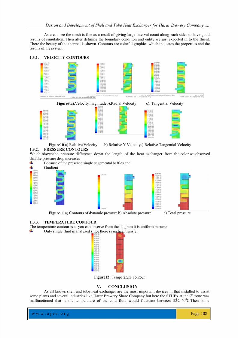
As u can see the mesh is fine as a result of giving large interval count along each sides to have good
results of simulation. Then after defining the boundary condition and entity we just exported in to the fluent.There the beauty of the thermal is shown. Contours are colorful graphics which indicates the properties and theresults of the system.
1.3.1.
VELOCITY CONTOURS
Figure9.a).Velocity magnitudeb).Radial Velocity c). Tangential Velocity
Figure10.a).Relative Velocity b).Relative Y Velocityc).Relative Tangential Velocity
1.3.2. PRESSURE CONTOURSWhich shows the pressure difference down the length of the heat exchanger from the color we observedthat the pressure drop increases
Because of the presence single segemental baffles andGradient
Figure11.a).Contours of dynamic pressure b).Absolute pressure c).Total pressure
1.3.3. TEMPERATURE CONTOURThe temperature contour is as you can observe from the diagram it is uniform becuose
Only single fluid is analyzed since there is no heat transfer
Figure12. Temperature contour
V. CONCLUSIONAs all knows shell and tube heat exchanger are the most important devices in that installed to assist
some plants and several industries like Harar Brewery Share Company but here the STHEx at the 9th
zone wasmalfunctioned that is the temperature of the cold fluid would fluctuate between 35
0C-40
0C.Then some

8/10/2019 Design and Development of Shell and Tube Heat Exchanger for Harar Brewery Company Pasteurizer Application (…
http://slidepdf.com/reader/full/design-and-development-of-shell-and-tube-heat-exchanger-for-harar-brewery-company 11/11
Design and Development of Shell and Tube Heat Exchanger for Harar Brewery Company ….
w w w . a j e r . o r g Page 109
optimization and redesign of the machine is done for both mechanical and thermal designs and the simulation fo
the heat transfer between the two fluid is analyzed using the concept of CFD (Computational Fluid Dynamics)using Gambit and Fluent software’s. The final result of the STHEx in HBSC which is the redesigned STHEXcan achieve or efficiently work to achieve the required outlet temperature 34 0C the temp at which the beer is
ready for customer for use.
REFERNCES[1]. Ramesh K. Shah, D. P. (2003). Fundamentals of Heat Exchanger Design. New Jercy and Canada: John Wiley & sons Inc
[2]. ZHANG Xiao-jun1, W. X.-L.-R. (2010). Numerical Simulation of Flow Field in Shellside of Heat Exchanger in Nuclear Power
Plant. CNKI, 50-62.
[3]. R. Hosseinia, A. H.-G. (April 2007). Experimental determination of shell side heat transfer coefficient and pressure drop for an oil
cooler shell-and-tube heat exchanger with three different tube bundles. Science Direct-ELSEVIER, 1001 – 1008.
[4]. Chang, T.-B. (2009). Enhancing the heat transfer performance of triangular-pitch shell-and-tube evaporators using an interior spray
technique. Research Gate, 14-19.
[5]. Boles, Y. A. (2006). Thermodynamics: An Engineering Approach. McGraw-Hill.
[6]. Kurmi, 2006. Design of Machine Elements
BibliographyDawit Bogale is currently working as a Lecturer in School of Mechanical and Industrial Engineering, Bahirdar University,
Bahirdar, Ethiopia. He did his BSc in Mechanical Engineer ing
at Jimma Universisty,Eth iopia and Special ized his MSc in
Applied Mechanics at Addis Ababa Institute of Technology
(AAiT) in the year 2012 and 2013 respectively.
“There's no place like home except Grandma's. This paper is dedicated to
My Grandmother who spent 15 years of her life with me. I love you my
grandmother Yeshiye Wedneh.”