Embed Size (px)
Citation preview

Design and Development of Quad-Band H-Shaped Microstrip Patch
Antenna for WiFi and LTE Applications
P.JOTHILAKSHMI1, R.K.VIGNESHWARAN
2, R.NARASIMMAN
3, B.PRAVEEN
4
1Assistant Professor
2,3,4 UG Students
Department of Electronics and Communication Engineering
Sri Venkateswara College of Engineering, Chennai, Tamilnadu, India
Sriperumbudur, Chennai
INDIA
Abstract: - The increasing demand in portable devices with wireless connectivity provides a challenge to design
a RF front antenna. Microstrip patch antennas are widely used because they are of light weight, compact, easy
to integrate. However the serious problem of patch antenna is their narrow band due to surface losses and large
size of patch for better performance. So for the antenna miniaturization and bandwidth improvement H-shaped
microstrip patch antenna was used. In this paper proposed a design of small sized, low profile patch antenna for
wireless applications. The antenna multiband capability could be achieved by introducing a slot in the
rectangular patch portion of h shaped patch antenna. The proposed antenna structure operates at four frequency
bands of 2.2 GHz, 2.4 GHz, 2.8 GHz, and 2.9 GHz for WiFi and LTE applications. The performance measures
of antenna return loss, voltage standing wave ratio, radiation pattern, gain, directivity and power were measured
and tabulated, which shows that the antenna performance was good and results obtained were optimum. The
simulation tool used for this design was Advanced Design System (ADS).
Key-Words: - Microstrip patch, Multiband Antenna, Gain, Return loss, Directivity, Radiation pattern.
1 Introduction
An antenna is an essential part of a radio system, is
defined as a device which can radiate and receive
electromagnetic energy in an efficient and desired
manner. Antenna is actually a transformer that
transforms electrical signals into electromagnetic
waves or vice versa. Requirements for conformal
antennas for airborne systems, increased bandwidth
requirements, and multi functionality have led to
heavy exploitation of printed (patch) or other slot-
type antennas and the use of powerful
computational tools for designing such antenna.
Needless to say, the commercial mobile
communications industry has been the catalyst for
the recent explosive growth in antenna design needs.
Certainly, the past decade has seen an extensive use
of antennas by the public for cellular, GPS, satellite,
wireless LAN for computers Wi-Fi, Bluetooth
technology, Radio Frequency ID devices, WiMAX,
and so on. However, future needs will be even
greater when a multitude of antennas are integrated
into say automobiles for all sorts of communication
needs and into a variety of portable devices and
sensors for monitoring and information gathering.
The concept of microstrip radiators was first
proposed by Deschamps in 1953. A patent was
issued in France in 1955 in the names of Gutton and
Baissinot. However, twenty years passed before
practical antennas were fabricated. Development
during the 1970 was accelerated by the availability
of good substrates with low loss tangent and
attractive thermal and mechanical properties,
improved photolithographic techniques, and better
theoretical models. The first practical antennas were
developed by Howell and Munson. Since then,
extensive research and development of microstrip
antennas and arrays, aimed at exploiting their
numerous advantages such as light weight, low
volume, low cost, conformal configuration,
compatibility with integrated circuits, and so on,
have led to diversified applications and to the
establishment of the topic as a separate entity within
the broad field of microwave antennas. The
importance of multiband antenna design was
discussed in the literature [1-10]. Microstrip
antennas have some distinct properties [11-12,21]
The bandwidth is directly proportional to
substrate thickness and width
The resonant input resistance is almost
independent of the substrate thickness
The resonant input resistance is proportional to
εr
The directivity is fairly insensitive to the
substrate thickness
WSEAS TRANSACTIONS on COMMUNICATIONSP. Jothilakshmi, R. K. Vigneshwaran, R. Narasimman, B. Praveen
E-ISSN: 2224-2864 234 Volume 13, 2014

The radiation efficiency is less than 100% due
to conductor loss, dielectric loss and surface
wave power.
2 Structure and design equation of
Microstrip patch antenna
A microstrip antenna in its simplest
configuration consists of a radiating patch on one
side of a dielectric substrate, which has a ground
plane on the other side. The patch conductors,
normally of copper or gold, can assume virtually
any shape, but regular shapes are generally used to
simplify analysis and performance prediction.
Ideally, the dielectric constant of the substrate
should be low to enhance the fringe fields that
account for the radiation. However, other
performance requirements may dictate the use of
substrate materials whose dielectric constants can be
greater than, say, and four. Various types of
substrates having a large range of dielectric constant
and loss tangent values have been developed. Some
of these substrates are flexible in nature, which
makes them suitable for conformal wraparound
antennas. Microstrip antennas are widely used in the
microwave frequency region because of their
simplicity and compatibility with printed-circuit
technology, making them easy to manufacture either
as stand-alone elements or as elements of arrays. A
Microstrip antenna consists of a planar radiating
structure over a ground plane separated by an
electrically thin layer of dielectric substrate. The
rectangular and circular patches are the basic and
most commonly used microstrip antennas. These
patches can be used for the simplest and the most
demanding applications. For an efficient radiator, a
practical width that leads to good radiation
efficiencies is given in equation 1. Equation 2 to
Equation 9 are used to calculate the design
parameters of microstrip patch antenna. These
equations are used to calculate any shape of patch
antenna.
2
12
r
rf
CW
(1)
Where c is the velocity of light, 3*108m/s,
εr is the dielectric constant of the substrate.
fr is the resonant frequency.
Effective Dielectric constant of the microstrip is
determined as
2
1
1212
)1(
2
)1(
W
hrrreff
(2)
Where εr is the dielectric constant of the substrate,
4.3mm,
h is the height of the substrate,
W is the width of the substrate.
Once width is found, Extension of the length
ΔL can be determined and denoted as,
)8.0)(258.0(
)264.0)(3.0(*412.0
h
Wreff
h
Wreffh
L
(3)
Where, εreff is the effective dielectric constant. Actual Length of the patch and also the substrate
can now be determined by using effective length as,
reffrf
ceffL
`2 (4)
LeffLL 2 (5)
Where, Leff is the effective length.
ΔL is the extension of length.
Feed line width can be modelled using the
transmission characteristics and the impedance
is given by,
A
W
r
W
h
r
Z'
4
11
814
4ln
122
1200
(6)
22
11
'
4
11
814
2
r
W
hrA
(7)
Where
'' WWW (8)
2
11
rWW
(9)
.
3 Structure and design equation of
Microstrip patch antenna
For designing H-shaped patch antenna first the
basic rectangular patch has been designed. From
that the L shaped patch has been developed and then
combined four L shaped patch to form a h shaped
patch antenna. For designing rectangular patch the
following design values had been adopted. In the
layout window of Advanced Design System the
design of multiband antenna is made and then
synthesised by giving a 50 Ω microstrip feed line.
The antenna parameters can be calculated using the
equation (1) to equation (9). The calculated design
parameters for the rectangular patch was shown in
Table1.
WSEAS TRANSACTIONS on COMMUNICATIONSP. Jothilakshmi, R. K. Vigneshwaran, R. Narasimman, B. Praveen
E-ISSN: 2224-2864 235 Volume 13, 2014
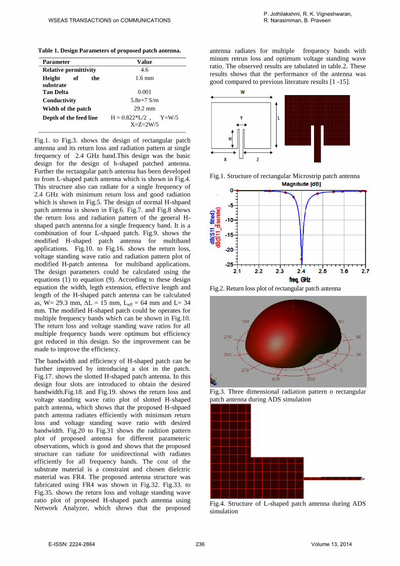
Table 1. Design Parameters of proposed patch antenna.
Parameter Value
Relative permittivity 4.6
Height of the
substrate
1.6 mm
Tan Delta 0.001
Conductivity 5.8e+7 S/m
Width of the patch 29.2 mm
Depth of the feed line H = 0.822*L/2 , Y=W/5
X=Z=2W/5
Fig.1. to Fig.3. shows the design of rectangular patch
antenna and its return loss and radiation pattern at single
frequency of 2.4 GHz band.This design was the basic
design for the design of h-shaped patched antenna.
Further the rectangular patch antenna has been developed
to from L-shaped patch antenna which is shown in Fig.4.
This structure also can radiate for a single frequency of
2.4 GHz with minimum return loss and good radiation
which is shown in Fig.5. The design of normal H-shpaed
patch antenna is shown in Fig.6. Fig.7. and Fig.8 shows
the return loss and radiation pattern of the general H-
shaped patch antenna.for a single frequency band. It is a
combination of four L-shpaed patch. Fig.9. shows the
modified H-shaped patch antenna for multiband
applications. Fig.10. to Fig.16. shows the return loss,
voltage standing wave ratio and radiation pattern plot of
modified H-patch antenna for multiband applications.
The design parameters could be calculated using the
equations (1) to equation (9). According to these design
equation the width, legth extension, effective length and
length of the H-shaped patch antenna can be calculated
as, W= 29.3 mm, ∆L = 15 mm, Leff = 64 mm and L= 34
mm. The modified H-shaped patch could be operates for
multiple frequency bands which can be shown in Fig.10.
The return loss and voltage standing wave ratios for all
multiple frequency bands were optimum but efficiency
got reduced in this design. So the improvement can be
made to improve the efficiency.
The bandwidth and efficiency of H-shaped patch can be
further improved by introducing a slot in the patch.
Fig.17. shows the slotted H-shaped patch antenna. In this
design four slots are introduced to obtain the desired
bandwidth.Fig.18. and Fig.19. shows the return loss and
voltage standing wave ratio plot of slotted H-shaped
patch antenna, which shows that the proposed H-shpaed
patch antenna radiates efficiently with minimum return
loss and voltage standing wave ratio with desired
bandwidth. Fig.20 to Fig.31 shows the radition pattern
plot of proposed antenna for different parameteric
observations, which is good and shows that the proposed
structure can radiate for unidirectional with radiates
efficiently for all frequency bands. The cost of the
substrate material is a constraint and chosen dielctric
material was FR4. The proposed antenna structure was
fabricated using FR4 was shown in Fig.32. Fig.33. to
Fig.35. shows the return loss and voltage standing wave
ratio plot of proposed H-shaped patch antenna using
Network Analyzer, which shows that the proposed
antenna radiates for multiple frequency bands with
minum retrun loss and optimum voltage standing wave
ratio. The observed results are tabulated in table.2. These
results shows that the performance of the antenna was
good compared to previous literature results [1 -15].
Fig.1. Structure of rectangular Microstrip patch antenna
Fig.2. Return loss plot of rectangular patch antenna
Fig.3. Three dimensional radiation pattern o rectangular
patch antenna during ADS simulation
Fig.4. Structure of L-shaped patch antenna during ADS
simulation
WSEAS TRANSACTIONS on COMMUNICATIONSP. Jothilakshmi, R. K. Vigneshwaran, R. Narasimman, B. Praveen
E-ISSN: 2224-2864 236 Volume 13, 2014

Fig.5. Return loss plot of L-shaped patch antenna
Fig.6. Structure of normal H-shaped patch antenna during
ADS simulation
Fig.7. Return loss plot of normal H-shaped patch antenna
during ADS simulation
Fig.8. 3-D radiation pattern of normal H-shaped patch
antenna during ADS simulation
Fig.9. Structure of modified H-shaped patch antenna
during ADS simulation
Fig.10. Return loss plot of modified H-shaped patch antenna
during ADS simulation
Fig.11. Voltage Standing Wave Ratio (VSWR) plot of
modified H-shaped patch antenna during ADS simulation
Fig.12. 3-D radiation pattern of modified H-shaped patch
antenna during ADS simulation
WSEAS TRANSACTIONS on COMMUNICATIONSP. Jothilakshmi, R. K. Vigneshwaran, R. Narasimman, B. Praveen
E-ISSN: 2224-2864 237 Volume 13, 2014

Fig.13. Polar plots of Gain, radiated power of a modified
H patch antenna at 1.38 GHz.
Fig.14. Polar plots of Gain, radiated power of a modified
H patch antenna at 2.18 GHz.
Fig.15. Polar plots of Gain, radiated power of a modified
H patch antenna at 2.78 GHz.
Fig.16. Polar plots of Gain, radiated power of a modified
H patch antenna at 3.48 GHz.
Fig.17. Structure of slotted H-shaped patch antenna during
ADS simulation
Fig.18. Return loss plot of slotted H-shaped patch antenna
during ADS simulation
Fig.19. Voltage Standing Wave Ratio plot of slotted H-
shaped patch antenna during ADS simulation.
Fig.20. Polar and 3-D radiation pattern of H –shaped slotted
microstrip patch for 2.2GHz operating frequency.
WSEAS TRANSACTIONS on COMMUNICATIONSP. Jothilakshmi, R. K. Vigneshwaran, R. Narasimman, B. Praveen
E-ISSN: 2224-2864 238 Volume 13, 2014
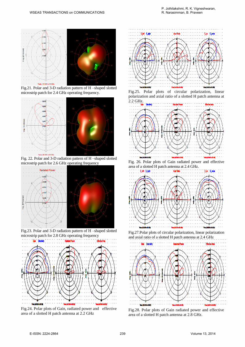
Fig.21. Polar and 3-D radiation pattern of H –shaped slotted
microstrip patch for 2.4 GHz operating frequency.
Fig. 22. Polar and 3-D radiation pattern of H –shaped slotted
microstrip patch for 2.6 GHz operating frequency
Fig.23. Polar and 3-D radiation pattern of H –shaped slotted
microstrip patch for 2.8 GHz operating frequency
Fig.24. Polar plots of Gain, radiated power and effective
area of a slotted H patch antenna at 2.2 GHz
Fig.25. Polar plots of circular polarization, linear
polarization and axial ratio of a slotted H patch antenna at
2.2 GHz.
Fig. 26. Polar plots of Gain radiated power and effective
area of a slotted H patch antenna at 2.4 GHz.
Fig.27.Polar plots of circular polarization, linear polarization
and axial ratio of a slotted H patch antenna at 2.4 GHz
Fig.28. Polar plots of Gain radiated power and effective
area of a slotted H patch antenna at 2.8 GHz.
WSEAS TRANSACTIONS on COMMUNICATIONSP. Jothilakshmi, R. K. Vigneshwaran, R. Narasimman, B. Praveen
E-ISSN: 2224-2864 239 Volume 13, 2014

Fig.29. Polar plots of circular polarization, linear
polarization and axial ratio of a slotted H-shaped patch
antenna at 2.8 GHz.
Fig. 30. Polar plots of Gain radiated power and effective
area of a slotted H-shaped patch antenna at 2.9 GHz.
Fig.31. Polar plots of circular polarization, linear
polarization and axial ratio of a slotted H-shaped patch
antenna at 2.9 GHz.
Fig.32. Fabricated multiband slotted H-shaped patch
antenna.
Fig.33. Fabricated multiband slotted H-shaped patch antenna
tested using network analyser
Fig.34. Return loss VBA file of H-shaped patch antenn
tested using network analyser.
Fig.35. Voltage standing wave ratio (VSWR) VBA file of
H-shaped patch antenna tested using net analyser.
WSEAS TRANSACTIONS on COMMUNICATIONSP. Jothilakshmi, R. K. Vigneshwaran, R. Narasimman, B. Praveen
E-ISSN: 2224-2864 240 Volume 13, 2014

Table.2. Observed Parameters of proposed slotted H-shaped
patch antenna.
Table.2 shows the observed return loss, VSWR
power, directivity and intensity observed during
simulation and measurement. The measured and
simulated and measured return loss and VSWR
shows that the proposed antenna structure radiates
efficiently for entire frequency band.
4 Conclusion The simulated and fabricated antenna results show
that the proposed antenna structure can be used for
WiFi and LTE applications. The H-shaped patch
antenna can also be used for higher bandwidth and
efficiency applications. The performance of the
proposed antenna structure can be further
improvised using Rogers substrate material. The
structure can be further miniaturized to perform for
UWB applications.
References: [1]. S.C. Gao, L. W. Li, M.-S. Leong, and T.S. Yeo, Analysis of an H-
shaped patch antenna by using the FDTD method, Progress In Electro Magnetic Research, vol.34, 2013, pp.165-187.
[2]. Hossein Msalekpoor and shahrokh Jam, Enhanced bandwidth of shorted patch antenna using folded patch techniques, IEEE Antennas and Wireless propagation Letters,2013,vol.12.
[3]. B. Davor, R. Bojan, Small H-shaped shorted patch antennas, Radio Engineering, vol. 17,2008 pp. 77.
[4]. U. Chakraborty, S. Chatterjee, S. K. Chowdhury and P. P. Sarkar, A Compact Microstrip Patch Antenna for Wireless Communication, Progress in Electromagnetics Research C, vol. 18, 2011, pp. 211-220.
[5]. Adenen Rajhi, Said Ghnimi and Ali Garssallah, Electrical Characteristics of a Dual-Band Microstrip Patch Antenna for GSM/ UMTS / WLAN”, International Journal of Communication Networks and Information Security (IJCNIS) , vol. 2, No. 1, 2010, pp.54-57.
[6]. L.Y. Cai, Y. Li, G. Zeng and H.C. Yang, Compact wideband antenna with double-fed structure having band notched characteristics, Electronics Letters, 11th November 2010, vol. 46, no. 23.
[7]. M. T. Islam, M. N. Shakib and N. Misran, Broadband E-H Shaped Microstrip Patch Antenna for Wireless Systems, Progress in Electromagnetics Research, vol. 98, 2009, pp. 163-173.
[8]. J.A.Ansari, Satya Kesh Dubey, Prabhakar Singh, R.U.Khan, and Babau R. Vishvakarma, Analysis of compact H-shaped microstrip antenna, Microwave Optical Technology Letters, vol. 50,2008, pp. 1779-1784.
[9]. A.A. Eldek, A.Z. Elsherbini, and C.E.Smith, Square slot antenna for dual wideband wireless communication systems, Journal of Electromagnetic Waves and Applications, USA, vol. 19, No. 12, 2005, pp. 1572-1581.
[10]. A.K.Shackelford, K.F.Lee and K.M.Luk, Design of small-size wideband width microstrip-patch antennas, IEEE Antennas Propagation. Magazine, vol.45, No.1,2003, pp.75–83.
[11]. A.F. Sheta, A novel H-shaped patch antenna, Microwave Optical Technology Letters, vol.29, 2001, pp.62–65.
[12]. F. Yang, X. X. Zhang, X. Ye, and Y. Rahmat-Samii, Wide-band Eshaped patch antennas for wireless communications, IEEE Transactions on Antennas Propagation, vol. 49, no. 7, pp. 1094–1100, Jul. 2001.
[13] D.Guha, Resonant frequency of circular microstrip antenna with and without air gaps, IEEE Transactions on Antennas and Propagation, vol.49, 2001, pp.55-59.
[14]. S.C. Gao, L.W.Li, T.S.Yeo and M.S. Leong, Low-cost, dual linearly-polarized microstrip patch array, IEE Proc. Microwave. Antennas and Propagation, vol. 148, 2001,pp.21–25.
[15]. C.S. Lee and K. H. Tseng, Size reduction of microstrip antennas, Electronic Letters, vol. 37, 2001, pp.1274-1275.
[16]. Waterhouse, R.B., “Broadband stacked shorted patch”, Electron. Letters, 1999, 35, (2), pp. 98–100.
[17]. W.S.Chen, Single-feed dual-frequency rectangular microstrip antenna with square slot, Electronics Letters, vol. 34, No. 3, 1998, 231–232.
[18]. D.H. Schaubert and K.S. Yngvesson, Experimental study of a microstrip array on high permittivity substrate, IEEE Transactions on Antennas and Propagation, 1986, pp. 92–97.
[19]. Y. Lo, D. Solomon, and W. Richards, Theory and experiment on microstrip antennas,” IEEE Trans. Antennas Propagation, vol. 27, pp. 137–145, Mar. 1979.
[20]. G.kumar, K.P.RAY, Broadband Microstrip Antennas. Norwood (MA, USA): Artech House, 2003.
[21]. J.D. Krauss, Antenna for All applications, Mcgraw-Hill Education Ltd, 2008.
Mrs.P.Jothilakshmi has received her
B.E. degree in Electronics and
Communication Engineering from
Thanthai Periyar Govt. Institute of
Technology,Vellore, India in 1996
and M.E degree from Mepco
Schlenk Engineering College,
Sivakasi, India in 2000. Currently
working as an Assistant Professor in Electronics and
Communication Engineering Department at Sri
Venkateswara College of Engineering, Chennai, India.
She has been a teacher for the past 15 years and has
guided more than thirty five B.E and M.E Students
projects. She has published more than thirty seven
conference and Journal papers both National and
International level. Pursuing Ph.D in the area wireless
antenna under the supervision of Dr.Mrs (S).Raju,
Professor and Head of the Department, Electronics and
Communication Engineering, Thiagarajar College of
Engineering, Madurai, India. She is a member in
professional societies ISTE , IETE and IAENG.
Parameters Frequency in GHz
2.2 2.4 2.8 2.9
Return loss
(below zero dB
scale)
Simulated
26.12 26.912 40.232 55.41
Return loss
(below zero dB
scale)
Measured
15.1 22 17.70 11.9
Voltage Standing
Wave Ratio
(Simulated)
1:2 1:1.22 1:1.194 1:1:12
Voltage Standing
Wave Ratio
(Measured)
1:1.38 1:1.122 1:1.287 1:1.65
Power radiated
(Watts)
0.002 0.0005 0.00269 0.0026
Directivity (dBi) 8.4 10.765 8.43216 10.590
Gain(dBi) 1 2.6716 2.88665 4.3345
Maximum
intensity
(Watts/steradian)
0.001 0.0005 0.00149 0.0022
WSEAS TRANSACTIONS on COMMUNICATIONSP. Jothilakshmi, R. K. Vigneshwaran, R. Narasimman, B. Praveen
E-ISSN: 2224-2864 241 Volume 13, 2014