Embed Size (px)
Citation preview

International Journal of Scientific Research and Engineering Development-– Volume 4 Issue 4, July- Aug 2021
Available at www.ijsred.com
ISSN : 2581-7175 ©IJSRED: All Rights are Reserved Page 258
Design and Development of Prototype Model of Pneumatic Bench Vice
M. Rajesh*1
,S.Ganesh Kumar Reddy*2
, P.H.Lokesh*3
, A.Adarsh Raj*4
, P.Pavan Kalyan*5
,
V.Kiran Kumar*6
*1Assistant Professor, Department of ME,GATES Institute of Technology, Department of Mechanical
Engineering, Gooty. A. P *2,3,4,5,6
UG Students, GATES Institute of Technology, Department of Mechanical Engineering, Gooty. A. P
ABSTRACT
Pneumatic systems are safer than electromotive systems because they may operate in flammable conditions without igniting or
exploding. Overloading a pneumatic system, on the other hand, will merely cause it to slide or stop working. When pneumatic
components are overworked, unlike electromotive components, they do not burn or become hot.Pneumatic systems do not emit
pollutants when they are in use. The air that is released is also treated differently. As a result, pneumatic systems can work in
areas where a high level of cleanliness is required. The production lines for integrated circuits are one example.the Pneumatic
plain vice used in drilling machine. Here the loading and unloading is quick. The job can be held more rigidly.
Keywords:PNEUMATIC BENCH VICE, DESIGN AND DRAWINGS BENCH WISE,
I. INTRODUCTION
Pneuma is a Greek word that means "breathing wind." The term pneumatics refers to the study of air movement and
phenomena. It is derived from the Greek word pneuma, which means "air." Today pneumatics is mainly understood to means
the application of air as a working medium in industry especially the driving and controlling of machines and equipment.
The moveable jaw is actuated by the screw rod in the mechanical type. The movable jaw is attached to one end, which goes
through a fixed type nut. When one end of the screw rod is rotated, it rotates in the nut, which moves the moveable jaw. The
reciprocating motion is converted here from the rotational motion.
One end of the piston rod is attached to the moveable jaw in the hydraulic type, and the piston slides in the cylinder. The
hydraulic fluid moves the piston, which moves the moveable jaw. Only a reciprocating movement is used here as the main
movement. The hydraulic and pneumatic types are the same. Instead of hydraulic fluid, air is employed in this application.
Pneumatics has for some considerable time between used for carrying out the simplest mechanical tasks in more recent times
has played a more important role in the development of pneumatic technology for automation.
Pneumatic systems operate on a supply of compressed air which must be made available in sufficient quantity and at a
pressure to suit the capacity of the system. When the pneumatic system is being adopted for the first time, however it wills
indeed the necessary to deal with the question of compressed air supply.Compressor capacity is the actual quantity of air
compressed and delivered and the volume expressed is that of the air at intake conditions namely at atmosphere pressure and
normal ambient temperature.
The compressibility of the air was first investigated by Robert Boyle in 1962 and that found that the product of pressure and
volume of a particular quantity of gas.
The usual written as
PV = C (or) PıVı = P2V2
RESEARCH ARTICLE OPEN ACCESS

International Journal of Scientific Research and Engineering Development-– Volume 4 Issue 4, July- Aug 2021
Available at www.ijsred.com
ISSN : 2581-7175 ©IJSRED: All Rights are Reserved Page 259
In this equation the pressure is the absolute pressured which for free is about 14.7 Psi and is of courage capable of maintaining
a column of mercury, nearly 30 inches high in an ordinary barometer. Any gas can be used in pneumatic system but air is the
mostly used system now a days
Pneumatic systems use pressurized gases to transmit and control power. Pneumatic systems typically use air as the fluid
medium because air is safe, low cost and readily available.
The Advantages of Pneumatics
1.Air used in pneumatic systems can be directly exhausted back in to the surrounding environment and hence the need of
special reservoirs and no- leak system designs are eliminated.
2.Pneumatic systems are simple and economical.
3.Control of pneumatic systems is easier.
The Disadvantages of Pneumatics:
1.Pneumatic systems exhibit spongy characteristics due to compressibility of air.
2.Pneumatic pressures are quite low due to compressor design limitations (less that 250 psi)..
II. SELECTION OF PNEUMATICS
Mechanization is broadly defined as the replacement of manual effort by mechanical power. Pneumatic is an attractive
medium for low cost mechanization particularly for sequential (or) repetitive operations. Many factories and plants
already have a compressed air system, which is capable of providing the power (or) energy requirements and the control
system (although equally pneumatic control systems may be economic and can be advantageously applied to other forms
of power).
The main advantage of an all-pneumatic system are usually economic and simplicity the latter reducing maintenance to a
low level. It can also have out standing advantages in terms of safety.
III. SELECTION CRITERIA FOR COMPRESSORS
A number of factors are involved in the selection criteria of a suitable air compressor.
These are dealt here briefly
1.Pressure: First of all, the pressure needed must be determined. Most air operated system and tools are designed to operate at a
pressure from 6 3105 to 7 3105 N/m2. A compressor ofnormal make and type would normally be suitable if this can assure a
pressure 6 3105 N/m2 in the distribution line laid down for a pneumatic tools and system.
2.Capacity: Another important factor in compressor selection is the capacity or volume of air required. This factor is sometimes
extremely difficult to evaluate.
Obviously, the unit selected should be large enough to supply all the air devices, which will be operating at any given time? If all
the air operation is continuous, the capacity required is simply the sum of air compression of each individual tool.
The main function of the air compressor is to compress the air up to the required pressure. The maximum capacity of the
compressor is 10 3105 to 12 3105 N/m2. This is a two stages or two-cylinder reciprocating air compressor. The two cylinders are
for low and high compression. The air pressure is measured at various places by the use of pressure gauges. V-belt and pulley are
used to drive the compressor.
3.Pressure Gauge: Pressure gauge is used for measuring the outlet pressure of air from the compressor. The gauge used is
Bourdon type pressure gauge. The maximum capacity of this gauge is 10 3105 to 12 3105 N/m2. The gauge is fitted at the outlet
of the air compressor.
International Journal of Scientific Research and Engineering Development-– Volume 4 Issue 4, July- Aug 2021
Available at www.ijsred.com
ISSN : 2581-7175 ©IJSRED: All Rights are Reserved Page 260
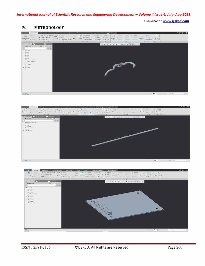
IV. METHODOLOGY

International Journal of Scientific Research and Engineering Development-– Volume 4 Issue 4, July- Aug 2021
Available at www.ijsred.com
ISSN : 2581-7175 ©IJSRED: All Rights are Reserved Page 261

International Journal of Scientific Research and Engineering Development-– Volume 4 Issue 4, July- Aug 2021
Available at www.ijsred.com
ISSN : 2581-7175 ©IJSRED: All Rights are Reserved Page 262

International Journal of Scientific Research and Engineering Development-– Volume 4 Issue 4, July- Aug 2021
Available at www.ijsred.com
ISSN : 2581-7175 ©IJSRED: All Rights are Reserved Page 263
Fig: Detailed Drawing of Pneumatic setup

International Journal of Scientific Research and Engineering Development-– Volume 4 Issue 4, July- Aug 2021
Available at www.ijsred.com
ISSN : 2581-7175 ©IJSRED: All Rights are Reserved Page 264
Fig: circuit diagram
Fig: work table arrangement

International Journal of Scientific Research and Engineering Development-– Volume 4 Issue 4, July- Aug 2021
Available at www.ijsred.com
ISSN : 2581-7175 ©IJSRED: All Rights are Reserved Page 265
Fig: PROTOTYPE MODEL OF PNEUMATIC BENCH VICE
V.ADVANTAGES AND DISADVANTAGES ADVANTAGES:
Idle time of the machine is reduced.
When compared with the mechanical vices, it consumes less time for clamping and unclamping the job.
It reduces the manual labour
Hence, production rate is higher
In this mechanism there is no backlash.
DISADVANTAGES:
Initial higher cost.
May be a choice of air leakage.
Cylinder stroke length is constant
• VI.APPLICATIONS AND SUGGESTION
APPLICATIONS:
To hold the job rigidly while machining.
For quick clamping and unclamping of the job.
SUGGESTION:
This is not only meant for drilling machine vice, using a large capacity cylinder and vice it can be used for clamping and
unclamping of the job for most of the machining processes.
VII. CONCLUSION
We conclude that this project made by us will be very helpful to all the machine tools for clamping and unclamping the
jobs, it may also be made as a standard available part in the market.
The design of this machine can be improved to reduce further manual work by incorporating the following ideas and
attachments.
By incorporating FRL (Filter, Regulator, and Lubrication) unit, the functioning of the machine can be improved.
The hand operated valves can be replaced by solenoid valves.
Limit switches can also be used to get the variable strokes.

International Journal of Scientific Research and Engineering Development-– Volume 4 Issue 4, July- Aug 2021
Available at www.ijsred.com
ISSN : 2581-7175 ©IJSRED: All Rights are Reserved Page 266
ACKNOWLEDGEMENT
We thank Mr. Rajesh M, who is the assistant professor of mechanical engineering department at Gates Institute of
technology, gooty. for hisguidance andsupport.
REFERENCES
1. AntonioEsposito-Fluidpowerwithapplication.PrenticehallofIndiaprivatelimited,1980.
2. Bolton,W.,Pneumaticandhydraulicsystems,Butterworth-Heinemann,JordanHill,Oxford,1997.
3. CatalogueofJanaticspneumaticproduct,JanaticsPrivateLimitedCoimbatore.
4. P.S.G.collegeoftechnology,Coimbatore
5. FestoDidacticKG–Fundamentalsofcontroltechnology,Esslingen-1998.
6. WernerDeppert/KurtStoll.,CuttingCostWithPneumatics,VogelBuchverlagWurzburg,1998
7. “Pneumaticvice”byMathankuma
8. “Pneumaticvice”bySaateh
9. “Pneumatic vice”byVijayGanapathi
10. “Pneumatic vice” by AmithMohapathra
11. “Pneumatic vice” by Chokalingam athilingam
12. https://www.youtube.com/watch?v=RkMY_b3vYtA
13.https://nevonprojects.com/design-and-fabrication-of-pneumatic-vice-project/
14. https://freeprojectsforall.com/pneumatic-vice/
15. https://youtu.be/UW2RkEROeME