Embed Size (px)
Citation preview
4
Design and Development of PID Controller-Based Active Suspension
System for Automobiles
Senthilkumar Mouleeswaran Department of Mechanical Engineering
PSG College of Technology Coimbatore
India
1. Introduction
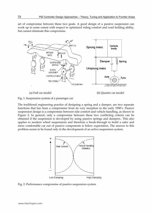
Suspension systems have been widely applied to vehicles, right from the horse-drawn carriage with flexible leaf springs fixed at the four corners, to the modern automobile with complex control algorithms. Every vehicle moving on the randomly profiled road is exposed to vibration which is harmful both for the passengers in terms of comfort and for the durability of the vehicle itself. Different disturbances occur when a vehicle leans over during cornering (rolling) and dives to the front during braking (pitching). Also, unpleasant vertical vibrations (bouncing) of the vehicle body can occur while driving over road irregularities. These dynamic motions do not only have an adverse effect on comfort but can also be unsafe, because the tyres might lose their grip on the road. Therefore the main task of a vehicle suspension is to ensure ride comfort and road holding for a variety of road conditions and vehicle maneuvers. This in turn would directly contribute to the safety of the user.
A typical suspension system used in automobiles is illustrated in Figure 1. In general, a good suspension should provide a comfortable ride and good handling within a reasonable range of deflection. Moreover, these criteria subjectively depend on the purpose of the vehicle. Sports cars usually have stiff, hard suspension with poor ride quality while luxury sedans have softer suspensions but with poor road handling capabilities. From a system design point of view, there are two main categories of disturbances on a vehicle, namely road and load disturbances. Road disturbances have the characteristics of large magnitude in low frequency (such as hills) and small magnitude in high frequency (such as road roughness). Load disturbances include the variation of loads induced by accelerating, braking and cornering. Therefore, in a good suspension design, importance is given to fairly reduce the disturbance to the outputs (e.g. vehicle height etc). A suspension system with proper cushioning needs to be “soft” against road disturbances and “hard” against load disturbances.
A heavily damped suspension will yield good vehicle handling, but also transfers much of the road input to the vehicle body, whereas a lightly damped suspension will yield a more comfortable ride, but would significantly reduce the stability of the vehicle at turns, lane change maneuvers, or during negotiating an exit ramp. Therefore, a suspension design is an
www.intechopen.com
PID Controller Design Approaches – Theory, Tuning and Application to Frontier Areas
72
art of compromise between these two goals. A good design of a passive suspension can work up to some extent with respect to optimized riding comfort and road holding ability, but cannot eliminate this compromise.
(a) Full car model (b) Quarter car model
Fig. 1. Suspension system of a passenger car
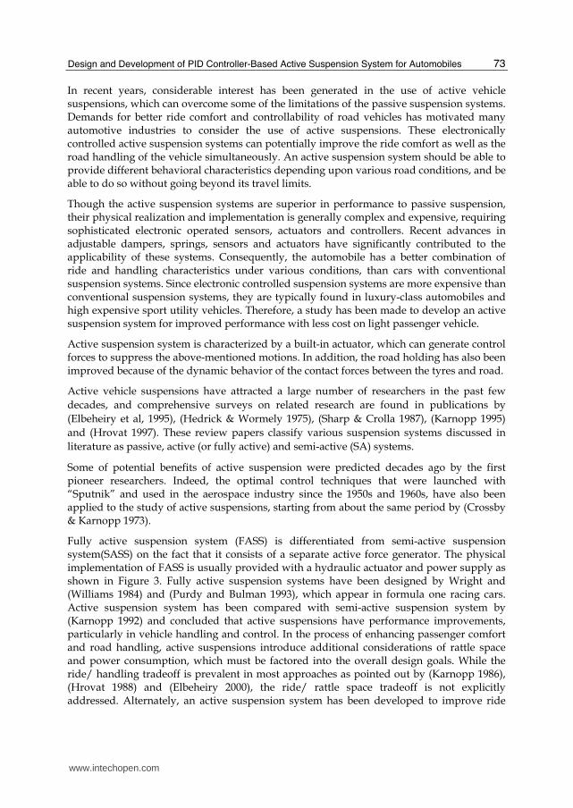
The traditional engineering practice of designing a spring and a damper, are two separate functions that has been a compromise from its very inception in the early 1900’s. Passive suspension design is a compromise between ride comfort and vehicle handling, as shown in Figure 2. In general, only a compromise between these two conflicting criteria can be obtained if the suspension is developed by using passive springs and dampers.. This also applies to modern wheel suspensions and therefore a break-through to build a safer and more comfortable car out of passive components is below expectation. The answer to this problem seems to be found only in the development of an active suspension system.
Fig. 2. Performance compromise of passive suspension system
www.intechopen.com
Design and Development of PID Controller-Based Active Suspension System for Automobiles
73
In recent years, considerable interest has been generated in the use of active vehicle suspensions, which can overcome some of the limitations of the passive suspension systems. Demands for better ride comfort and controllability of road vehicles has motivated many automotive industries to consider the use of active suspensions. These electronically controlled active suspension systems can potentially improve the ride comfort as well as the road handling of the vehicle simultaneously. An active suspension system should be able to provide different behavioral characteristics depending upon various road conditions, and be able to do so without going beyond its travel limits.
Though the active suspension systems are superior in performance to passive suspension, their physical realization and implementation is generally complex and expensive, requiring sophisticated electronic operated sensors, actuators and controllers. Recent advances in adjustable dampers, springs, sensors and actuators have significantly contributed to the applicability of these systems. Consequently, the automobile has a better combination of ride and handling characteristics under various conditions, than cars with conventional suspension systems. Since electronic controlled suspension systems are more expensive than conventional suspension systems, they are typically found in luxury-class automobiles and high expensive sport utility vehicles. Therefore, a study has been made to develop an active suspension system for improved performance with less cost on light passenger vehicle.
Active suspension system is characterized by a built-in actuator, which can generate control forces to suppress the above-mentioned motions. In addition, the road holding has also been improved because of the dynamic behavior of the contact forces between the tyres and road.
Active vehicle suspensions have attracted a large number of researchers in the past few
decades, and comprehensive surveys on related research are found in publications by
(Elbeheiry et al, 1995), (Hedrick & Wormely 1975), (Sharp & Crolla 1987), (Karnopp 1995)
and (Hrovat 1997). These review papers classify various suspension systems discussed in
literature as passive, active (or fully active) and semi-active (SA) systems.
Some of potential benefits of active suspension were predicted decades ago by the first pioneer researchers. Indeed, the optimal control techniques that were launched with “Sputnik” and used in the aerospace industry since the 1950s and 1960s, have also been applied to the study of active suspensions, starting from about the same period by (Crossby & Karnopp 1973).
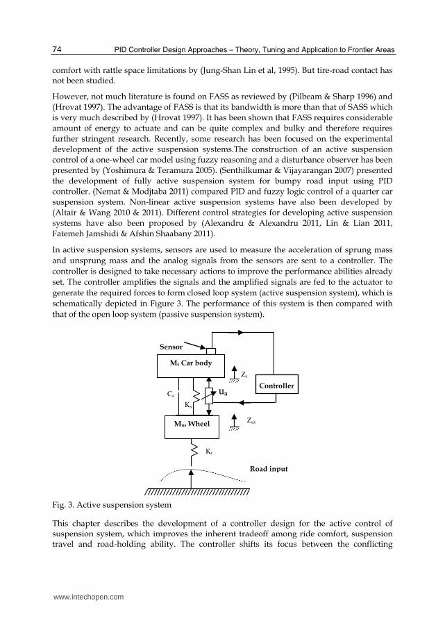
Fully active suspension system (FASS) is differentiated from semi-active suspension system(SASS) on the fact that it consists of a separate active force generator. The physical implementation of FASS is usually provided with a hydraulic actuator and power supply as shown in Figure 3. Fully active suspension systems have been designed by Wright and (Williams 1984) and (Purdy and Bulman 1993), which appear in formula one racing cars. Active suspension system has been compared with semi-active suspension system by (Karnopp 1992) and concluded that active suspensions have performance improvements, particularly in vehicle handling and control. In the process of enhancing passenger comfort and road handling, active suspensions introduce additional considerations of rattle space and power consumption, which must be factored into the overall design goals. While the ride/ handling tradeoff is prevalent in most approaches as pointed out by (Karnopp 1986), (Hrovat 1988) and (Elbeheiry 2000), the ride/ rattle space tradeoff is not explicitly addressed. Alternately, an active suspension system has been developed to improve ride
www.intechopen.com
PID Controller Design Approaches – Theory, Tuning and Application to Frontier Areas
74
comfort with rattle space limitations by (Jung-Shan Lin et al, 1995). But tire-road contact has not been studied.
However, not much literature is found on FASS as reviewed by (Pilbeam & Sharp 1996) and
(Hrovat 1997). The advantage of FASS is that its bandwidth is more than that of SASS which
is very much described by (Hrovat 1997). It has been shown that FASS requires considerable
amount of energy to actuate and can be quite complex and bulky and therefore requires
further stringent research. Recently, some research has been focused on the experimental
development of the active suspension systems.The construction of an active suspension
control of a one-wheel car model using fuzzy reasoning and a disturbance observer has been
presented by (Yoshimura & Teramura 2005). (Senthilkumar & Vijayarangan 2007) presented
the development of fully active suspension system for bumpy road input using PID
controller. (Nemat & Modjtaba 2011) compared PID and fuzzy logic control of a quarter car
suspension system. Non-linear active suspension systems have also been developed by
(Altair & Wang 2010 & 2011). Different control strategies for developing active suspension
systems have also been proposed by (Alexandru & Alexandru 2011, Lin & Lian 2011,
Fatemeh Jamshidi & Afshin Shaabany 2011).
In active suspension systems, sensors are used to measure the acceleration of sprung mass
and unsprung mass and the analog signals from the sensors are sent to a controller. The
controller is designed to take necessary actions to improve the performance abilities already
set. The controller amplifies the signals and the amplified signals are fed to the actuator to
generate the required forces to form closed loop system (active suspension system), which is
schematically depicted in Figure 3. The performance of this system is then compared with
that of the open loop system (passive suspension system).
Fig. 3. Active suspension system
This chapter describes the development of a controller design for the active control of suspension system, which improves the inherent tradeoff among ride comfort, suspension travel and road-holding ability. The controller shifts its focus between the conflicting
ua
Zs
Ks
Controller
Road input
Kt
Zus
Ca
Mus Wheel
Ms Car body
Sensor
www.intechopen.com
Design and Development of PID Controller-Based Active Suspension System for Automobiles
75
objectives of ride comfort, rattle space utilization and road-holding ability, softening the suspension when rattle space is small and stiffening it as it approaches the travel limits. The developed design allows the suspension system to behave differently in different operating conditions, without compromising on road-holding ability. The effectiveness of this control method has been explained by data from time domains. Proportional-Integral-Derivative (PID) controller including hydraulic dynamics has been developed. The displacement of hydraulic actuator and spool valve is modeled. The Ziegler – Nichols tuning rules are used to determine proportional gain, reset rate and derivative time of PID controller (Ogata 1990). Simulink diagram of active suspension system is developed and analyzed using MATLAB software. The investigations on the performance of the developed active suspension control are demonstrated through comparative simulations in this chapter.
2. Active suspension system
Active suspension systems add hydraulic actuators to the passive components of suspension system as shown in Figure 3. The advantage of such a system is that even if the active hydraulic actuator or the control system fails, the passive components come into action. The equations of motion are written as,
M z + K (z - z ) + C (z - z ) - u = 0s s s s us a s us aM z + K (z - z ) + C (z - z ) + K (z - z ) + u = 0us us s us s a us s t us r a
(1)
where ua is the control force from the hydraulic actuator. It can be noted that if the control force ua = 0, then Equation (1) becomes the equation of passive suspension system.
Considering ua as the control input, the state-space representation of Equation (1) becomes,
- -
- - -
1 2
2 s 1 3 a 2 4s
3 4
4 s 1 3 a 2 4 t 3 rus
z z
1z - [K (z z ) C (z z )]
M
z z
1z [K (z z ) C (z z ) K (z z )]
M
(2)
where , 1 2 3 usz z , z S Sz z z and 4 usz z
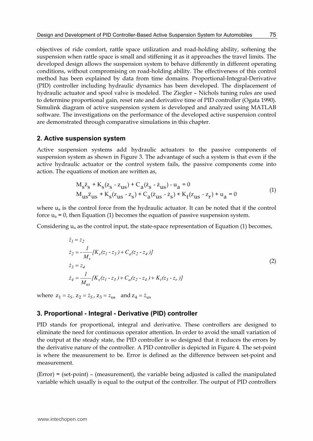
3. Proportional - Integral - Derivative (PID) controller
PID stands for proportional, integral and derivative. These controllers are designed to
eliminate the need for continuous operator attention. In order to avoid the small variation of
the output at the steady state, the PID controller is so designed that it reduces the errors by
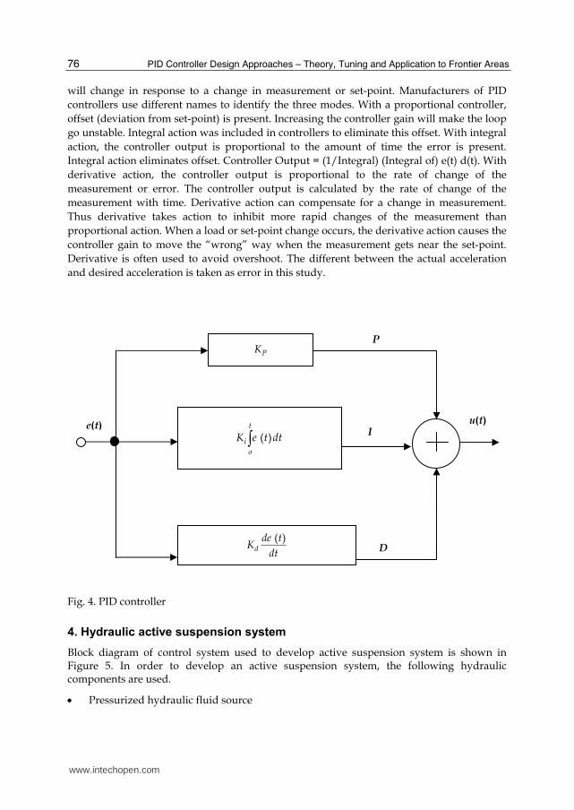
the derivative nature of the controller. A PID controller is depicted in Figure 4. The set-point
is where the measurement to be. Error is defined as the difference between set-point and
measurement.
(Error) = (set-point) – (measurement), the variable being adjusted is called the manipulated
variable which usually is equal to the output of the controller. The output of PID controllers
www.intechopen.com
PID Controller Design Approaches – Theory, Tuning and Application to Frontier Areas
76
will change in response to a change in measurement or set-point. Manufacturers of PID
controllers use different names to identify the three modes. With a proportional controller,
offset (deviation from set-point) is present. Increasing the controller gain will make the loop
go unstable. Integral action was included in controllers to eliminate this offset. With integral
action, the controller output is proportional to the amount of time the error is present.
Integral action eliminates offset. Controller Output = (1/Integral) (Integral of) e(t) d(t). With
derivative action, the controller output is proportional to the rate of change of the
measurement or error. The controller output is calculated by the rate of change of the
measurement with time. Derivative action can compensate for a change in measurement.
Thus derivative takes action to inhibit more rapid changes of the measurement than
proportional action. When a load or set-point change occurs, the derivative action causes the
controller gain to move the “wrong” way when the measurement gets near the set-point.
Derivative is often used to avoid overshoot. The different between the actual acceleration
and desired acceleration is taken as error in this study.
Fig. 4. PID controller
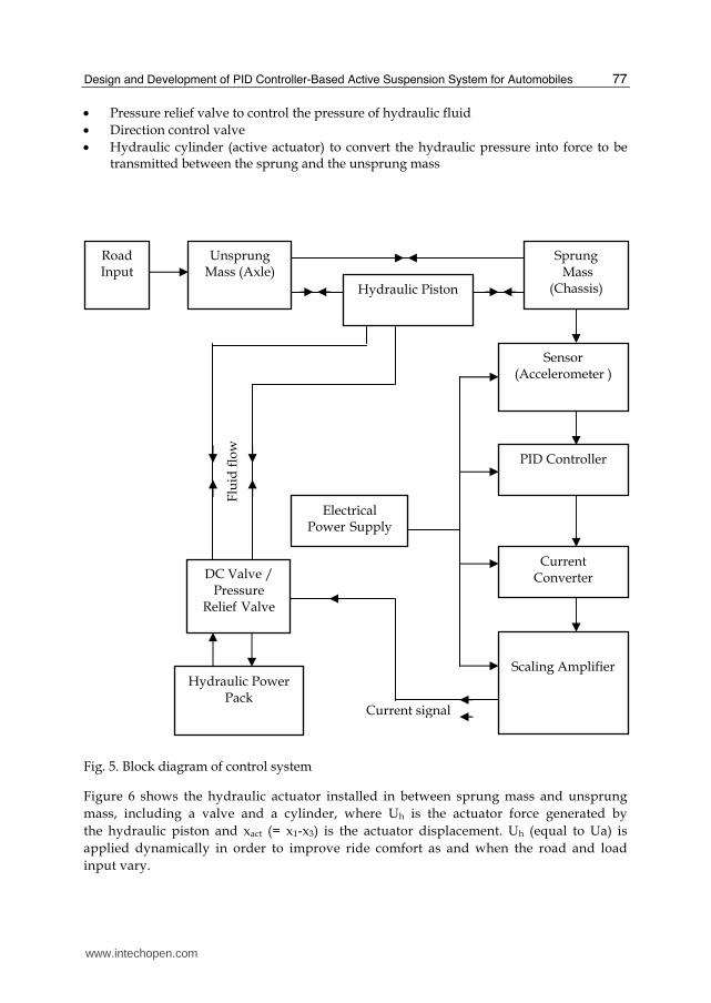
4. Hydraulic active suspension system
Block diagram of control system used to develop active suspension system is shown in Figure 5. In order to develop an active suspension system, the following hydraulic components are used.
Pressurized hydraulic fluid source
PK
( ) t
i
o
K e t dt
( ) d
de tK
dt
e(t)
P
I
D
u(t)
www.intechopen.com
Design and Development of PID Controller-Based Active Suspension System for Automobiles
77
Pressure relief valve to control the pressure of hydraulic fluid
Direction control valve
Hydraulic cylinder (active actuator) to convert the hydraulic pressure into force to be transmitted between the sprung and the unsprung mass
Fig. 5. Block diagram of control system
Figure 6 shows the hydraulic actuator installed in between sprung mass and unsprung
mass, including a valve and a cylinder, where Uh is the actuator force generated by
the hydraulic piston and xact (= x1-x3) is the actuator displacement. Uh (equal to Ua) is
applied dynamically in order to improve ride comfort as and when the road and load
input vary.
Current signal
Unsprung Mass (Axle)
Hydraulic Piston
Sensor (Accelerometer )
PID Controller
Current Converter
Scaling Amplifier
Road Input
Electrical Power Supply
DC Valve / Pressure
Relief Valve
Hydraulic Power Pack
Sprung Mass
(Chassis)
Flu
id f
low
www.intechopen.com
PID Controller Design Approaches – Theory, Tuning and Application to Frontier Areas
78
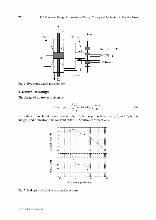
Fig. 6. Hydraulic valve and cylinder
5. Controller design
The design of controller is given by,
p
0
K e(t)t
pc p d
i
K de(t)U e(t)dt K T
T dt (3)
Uc is the current input from the controller, Kp is the proportional gain, Ti and Td is the integral and derivative time constant of the PID controller respectively.
Fig. 7. Bode plot of passive suspension system
Au
Uh
x6
ql
xact
Uh
Vl x5
Vu
Ps Supply
Return
Return
qu
Frequency (rad/sec)
Ph
ase
(deg
) M
agn
itu
de
(dB
)
www.intechopen.com
Design and Development of PID Controller-Based Active Suspension System for Automobiles
79
The values of gain margin and phase margin obtained from the frequency response plot of car body displacement of the passive suspension system shown in Figure 7 are used to determine the tuning parameters of the PID controller for the active quarter car model. The Ziegler-Nichols tuning rules are used to determine proportional gain, reset rate and derivative time of PID controller.
5.1 Tuning of PID controller
The process of selecting the controller parameters to meet given performance specification is known as controller tuning. Zeigler and Nichols suggested rules for tuning PID controllers (meaning to set values Kp, Ti, Td) based on experimental step responses or based on the values of Kp that results in marginal stability when only proportional control action is used. Ziegler-Nichols rules, which are briefly presented in the section 5.1.1 are very much useful. Such rules suggest a set of values of Kp, Ti, and Td that will give a stable operation of the system. However, the resulting system may exhibit a large maximum overshoot in the step response, which is unacceptable. In such a case we need a series of fine tunings until an acceptable results is obtained. In fact, the Zeigler-Nichols tuning rules give an educated guess for the parameter values and provide a starting point for fine tuning, rather than giving the final settings for Kp, Ti, and Td in a single shot.
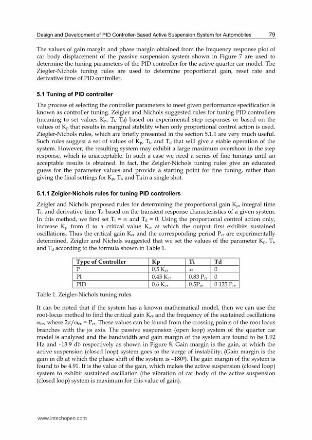
5.1.1 Zeigler-Nichols rules for tuning PID controllers
Zeigler and Nichols proposed rules for determining the proportional gain Kp, integral time Ti, and derivative time Td based on the transient response characteristics of a given system.
In this method, we first set Ti = and Td = 0. Using the proportional control action only, increase Kp from 0 to a critical value Kcr at which the output first exhibits sustained oscillations. Thus the critical gain Kcr and the corresponding period Pcr are experimentally determined. Zeigler and Nichols suggested that we set the values of the parameter Kp, Ti, and Td according to the formula shown in Table 1.
Type of Controller Kp Ti Td
P 0.5 Kcr 0
PI 0.45 Kcr 0.83 Pcr 0
PID 0.6 Kcr 0.5Pcr 0.125 Pcr
Table 1. Zeigler-Nichols tuning rules
It can be noted that if the system has a known mathematical model, then we can use the root-locus method to find the critical gain Kcr and the frequency of the sustained oscillations
cr, where 2/cr = Pcr. These values can be found from the crossing points of the root locus
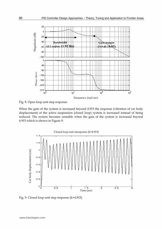
branches with the j axis. The passive suspension (open loop) system of the quarter car model is analyzed and the bandwidth and gain margin of the system are found to be 1.92 Hz and –13.9 db respectively as shown in Figure 8. Gain margin is the gain, at which the active suspension (closed loop) system goes to the verge of instability; (Gain margin is the gain in db at which the phase shift of the system is –1800). The gain margin of the system is found to be 4.91. It is the value of the gain, which makes the active suspension (closed loop) system to exhibit sustained oscillation (the vibration of car body of the active suspension (closed loop) system is maximum for this value of gain).
www.intechopen.com
PID Controller Design Approaches – Theory, Tuning and Application to Frontier Areas
80
Fig. 8. Open loop unit step response
When the gain of the system is increased beyond 4.915 the response (vibration of car body
displacement) of the active suspension (closed loop) system is increased instead of being
reduced. The system becomes unstable when the gain of the system is increased beyond
4.915 which is shown in Figure 9.
Fig. 9. Closed loop unit step response (k>4.915)
Bandwidth
12.1 rad/sec (1.92 Hz)
Gain margin
-13.9 db (4.91)
Frequency (rad/sec)
Mag
nit
ud
e (d
B)
Ph
ase
(deg
)
Time (sec)
Car
bo
dy
dis
pla
cem
ent
(cm
)
Closed loop unit steesponse (k=4.915)
www.intechopen.com
Design and Development of PID Controller-Based Active Suspension System for Automobiles
81
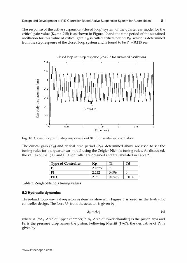
The response of the active suspension (closed loop) system of the quarter car model for the critical gain value (Kcr = 4.915) is as shown in Figure 10 and the time period of the sustained oscillation for this value of critical gain Kcr is called critical period Pcr, which is determined from the step response of the closed loop system and is found to be Pcr = 0.115 sec.
Fig. 10. Closed loop unit step response (k=4.915) for sustained oscillation
The critical gain (Kcr) and critical time period (Pcr), determined above are used to set the
tuning rules for the quarter car model using the Zeigler-Nichols tuning rules. As discussed,
the values of the P, PI and PID controller are obtained and are tabulated in Table 2.
Type of Controller Kp Ti Td
P 2.4575 0
PI 2.212 0.096 0
PID 2.95 0.0575 0.014
Table 2. Zeigler-Nichols tuning values
5.2 Hydraulic dynamics
Three-land four-way valve-piston system as shown in Figure 6 is used in the hydraulic controller design. The force Uh from the actuator is given by,
h LU AP (4)
where A (=Au, Area of upper chamber; = Al, Area of lower chamber) is the piston area and PL is the pressure drop across the piston. Following Merritt (1967), the derivative of PL is given by
Tu = 0.115
Time (sec)
Car
bo
dy
dis
pla
cem
ent
(cm
)
Closed loop unit step response (k=4.915 for sustained oscillation)
www.intechopen.com
PID Controller Design Approaches – Theory, Tuning and Application to Frontier Areas
82
2 44
tL tp L
VP Q C P A(x x ) (5)
where Vt is the total actuator volume, is the effective bulk modulus of the fluid, Q is the
hydraulic load flow (Q = qu+ql), where qu and ql are the flows in the upper and lower
chamber respectively and Ctp is the total leakage coefficient of the piston. In addition, the
valve load flow equation is given by
-1
6 6 5Q C ωx P sgn(x )xd sρ (6)
where Cd is the discharge coefficient, is the spool valve area gradient, x5 is the pressure inside the chamber of hydraulic piston and x6 = xsp is the valve displacement from its closed
position, is the hydraulic fluid density and Ps is the supply pressure, Since, the term 6 5sP sgn(x )x may become negative, Equation (6) is replaced with the corrected flow
equation as,
6 5 6 6 51
s d sQ sgn P sgn(x )x C x P sgn(x )x (7)
Finally, the spool valve displacement is controlled by the input to the valve Uc, described by
Equation (3), which could be a current or voltage signal. Equations (2) to (7) used to derive
the equation of the active suspension system, including the hydraulic dynamics are
rewritten as Equation (8).
1 2
s a s a l2 1 2 3 4 5
s s s s s
3 4
s a s t a l t4 1 2 3 4 5
us us us us us us
5 5 2 4 6 3
66 c
x = x
K C K C Ax = x + x + x + x + x
M M M M M
x =x
K C K +K C A Kx = x + x + x + x + x + r
M M M M M M
x =βx +A(x -x )+x ┱x
x = +Uτ
(8)
where, 3 6 5 6 5s ssgn P sgn(x )x P sgn(x )x
Thus Equation (8) becomes state feedback model of active suspension system including
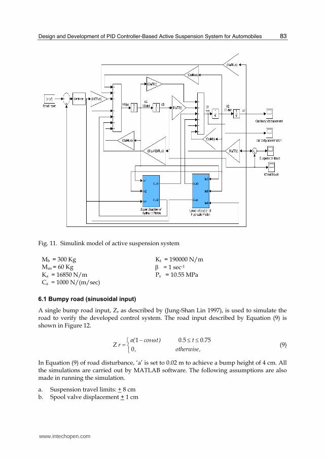
hydraulic dynamics. Figure 11 represents the Simulink model of active suspension
system.
6. Simulation
To ensure that our controller design achieves the desired objective, the open loop passive and closed loop active suspension system are simulated with the following values.
www.intechopen.com
Design and Development of PID Controller-Based Active Suspension System for Automobiles
83
Fig. 11. Simulink model of active suspension system
Mb = 300 Kg Kt = 190000 N/m Mus = 60 Kg = 1 sec-1 Ka = 16850 N/m Ps = 10.55 MPa Ca = 1000 N/(m/sec)
6.1 Bumpy road (sinusoidal input)
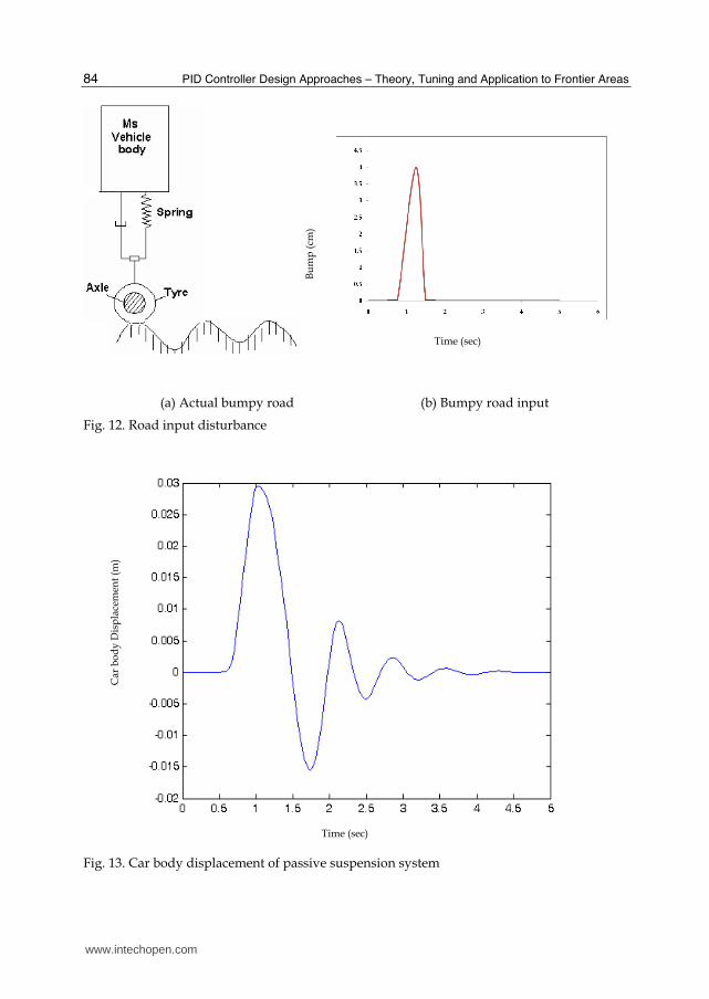
A single bump road input, Zr as described by (Jung-Shan Lin 1997), is used to simulate the road to verify the developed control system. The road input described by Equation (9) is shown in Figure 12.
Z1 0 5 0 75
0
a( cos t) . t .r
, otherwise,
(9)
In Equation (9) of road disturbance, ‘a’ is set to 0.02 m to achieve a bump height of 4 cm. All the simulations are carried out by MATLAB software. The following assumptions are also made in running the simulation.
a. Suspension travel limits: + 8 cm b. Spool valve displacement + 1 cm
www.intechopen.com
PID Controller Design Approaches – Theory, Tuning and Application to Frontier Areas
84
(a) Actual bumpy road (b) Bumpy road input
Fig. 12. Road input disturbance
Fig. 13. Car body displacement of passive suspension system
Time (sec)
Bu
mp
(cm
)
Car
bo
dy
Dis
pla
cem
ent
(m)
Time (sec)
www.intechopen.com
Design and Development of PID Controller-Based Active Suspension System for Automobiles
85
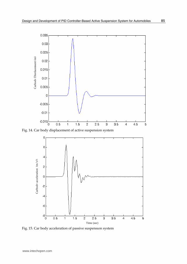
Fig. 14. Car body displacement of active suspension system
Fig. 15. Car body acceleration of passive suspension system
Time (sec)
Car
bo
dy
Dis
pla
cem
ent
(m)
Car
bo
dy
acc
eler
atio
n (
m/
s2)
www.intechopen.com
PID Controller Design Approaches – Theory, Tuning and Application to Frontier Areas
86
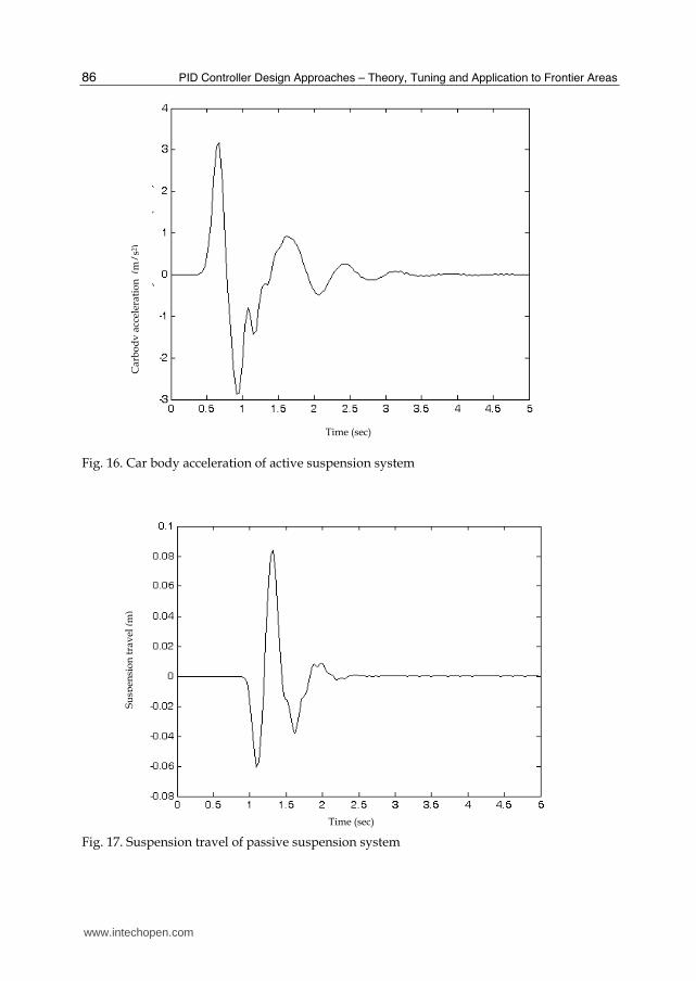
Fig. 16. Car body acceleration of active suspension system
Fig. 17. Suspension travel of passive suspension system
Car
bo
dy
acc
eler
atio
n (
m/
s2)
Time (sec)
Time (sec)
Su
spen
sio
n t
rav
el (
m)
www.intechopen.com
Design and Development of PID Controller-Based Active Suspension System for Automobiles
87
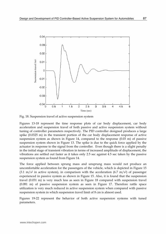
Fig. 18. Suspension travel of active suspension system
Figures 13-18 represent the time response plots of car body displacement, car body acceleration and suspension travel of both passive and active suspension system without tuning of controller parameters respectively. The PID controller designed produces a large spike (0.0325 m) in the transient portion of the car body displacement response of active suspension system as shown in Figure 14, compared to the response (0.03 m) of passive suspension system shown in Figure 13. The spike is due to the quick force applied by the actuator in response to the signal from the controller. Even though there is a slight penalty in the initial stage of transient vibration in terms of increased amplitude of displacement, the vibrations are settled out faster as it takes only 2.5 sec against 4.5 sec taken by the passive suspension system as found from Figure 14.
The force applied between sprung mass and unsprung mass would not produce an
uncomfortable acceleration for the passengers of the vehicle, which is depicted in Figure 15
(3.1 m/s2 in active system), in comparison with the acceleration (6.7 m/s2) of passenger
experienced in passive system as shown in Figure 15. Also, it is found that the suspension
travel (0.031 m) is very much less as seen in Figure 18 compared with suspension travel
(0.081 m) of passive suspension system as seen in Figure 17. Therefore rattle space
utilization is very much reduced in active suspension system when compared with passive
suspension system in which suspension travel limit of 8 cm is almost used.
Figures 19-22 represent the behavior of both active suspension systems with tuned parameters.
Time (sec)
Su
spen
sio
n t
rav
el (
m)
www.intechopen.com
PID Controller Design Approaches – Theory, Tuning and Application to Frontier Areas
88
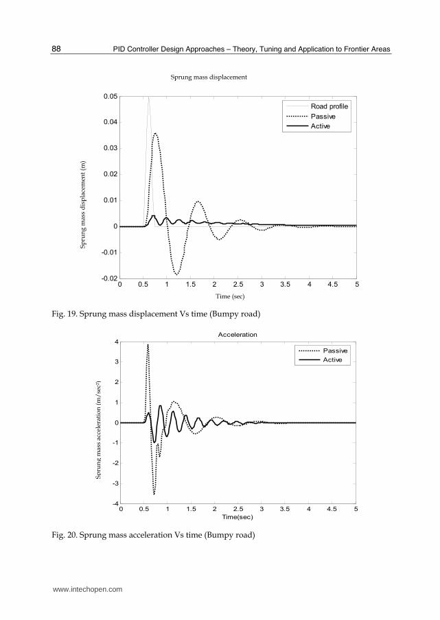
Fig. 19. Sprung mass displacement Vs time (Bumpy road)
Fig. 20. Sprung mass acceleration Vs time (Bumpy road)
0 0.5 1 1.5 2 2.5 3 3.5 4 4.5 5-0.02
-0.01
0
0.01
0.02
0.03
0.04
0.05p
gp
()
Road profile
Passive
Active
Time (sec)
Sp
run
g m
ass
dis
pla
cem
ent
(m)
0 0.5 1 1.5 2 2.5 3 3.5 4 4.5 5-4
-3
-2
-1
0
1
2
3
4
Time(sec)
Accele
ration(m
/sec
2)
Acceleration
Passive
Active
Sp
run
g m
ass
acce
lera
tio
n (
m/
sec2
)
Sprung mass displacement
www.intechopen.com
Design and Development of PID Controller-Based Active Suspension System for Automobiles
89
0 0.5 1 1.5 2 2.5 3 3.5 4 4.5 5-0.05
-0.04
-0.03
-0.02
-0.01
0
0.01
0.02
0.03
0.04
Time(sec)
Suspensio
n t
ravel(m
)
Suspension travel
Passive
Active
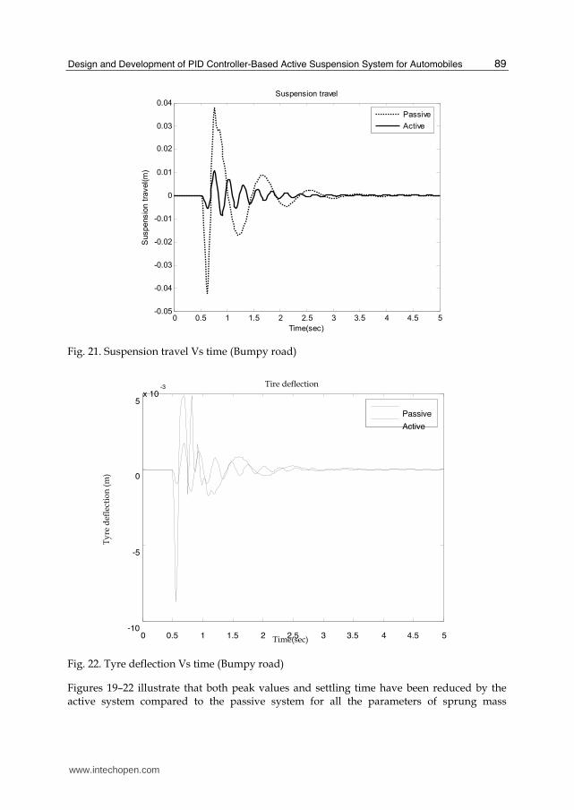
Fig. 21. Suspension travel Vs time (Bumpy road)
Fig. 22. Tyre deflection Vs time (Bumpy road)
Figures 19–22 illustrate that both peak values and settling time have been reduced by the active system compared to the passive system for all the parameters of sprung mass
0 0.5 1 1.5 2 2.5 3 3.5 4 4.5 5-10
-5
0
5x 10
-3
Time(sec)
Tire deflection
PassiveActive
Ty
re d
efle
ctio
n (
m)
www.intechopen.com
PID Controller Design Approaches – Theory, Tuning and Application to Frontier Areas
90
displacement, sprung mass acceleration (ride comfort), suspension travel and tyre deflection (road holding). Table 3 gives the percentage reduction in peak values of the various parameters for the sinusoidal bumpy road input.
Parameter Passive Active % Reduction
Sprung Mass Acceleration 3.847 m/s2 0.845m/s2 78.03
Suspension Travel 0.038 m 0.011 m 71.05
Tyre Deflection 0.005 m 0.002 m 60.00
Table 3. Reduction in peak values different parameters (Bumpy road)
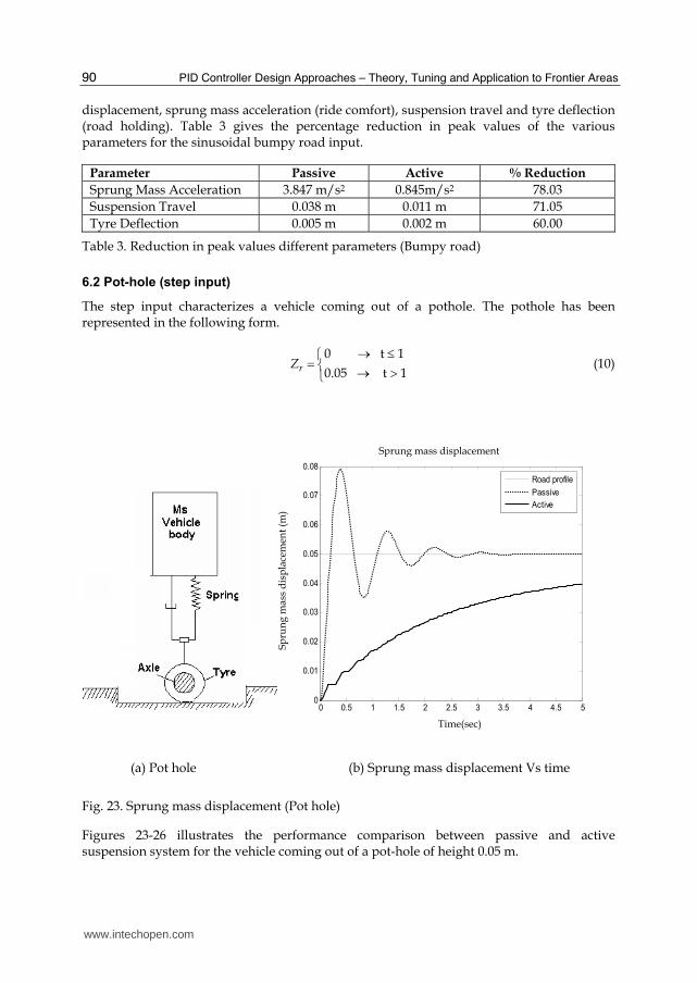
6.2 Pot-hole (step input)
The step input characterizes a vehicle coming out of a pothole. The pothole has been represented in the following form.
0 t 1
0.05 t 1rZ (10)
(a) Pot hole (b) Sprung mass displacement Vs time
Fig. 23. Sprung mass displacement (Pot hole)
Figures 23-26 illustrates the performance comparison between passive and active suspension system for the vehicle coming out of a pot-hole of height 0.05 m.
Sp
run
g m
ass
dis
pla
cem
ent
(m)
0 0.5 1 1.5 2 2.5 3 3.5 4 4.5 50
0.01
0.02
0.03
0.04
0.05
0.06
0.07
0.08Sprung Mass Displacement
Road profile
Passive
Active
Sprung mass displacement
Time(sec)
www.intechopen.com
Design and Development of PID Controller-Based Active Suspension System for Automobiles
91
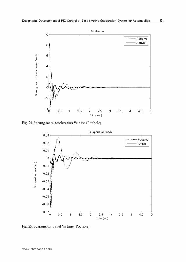
Fig. 24. Sprung mass acceleration Vs time (Pot hole)
Fig. 25. Suspension travel Vs time (Pot hole)
Sp
run
g m
ass
acce
lera
tio
n (
m/
sec2
)
Time(sec)
0 0.5 1 1.5 2 2.5 3 3.5 4 4.5 5-4
-2
0
2
4
6
8
10
Passive
Active
Acceleratio
Su
spen
sio
n t
rav
el (
m)
0 0.5 1 1.5 2 2.5 3 3.5 4 4.5 5-0.07
-0.06
-0.05
-0.04
-0.03
-0.02
-0.01
0
0.01
0.02
0.03Suspension travel
Passive
Active
Time (sec)
www.intechopen.com
PID Controller Design Approaches – Theory, Tuning and Application to Frontier Areas
92
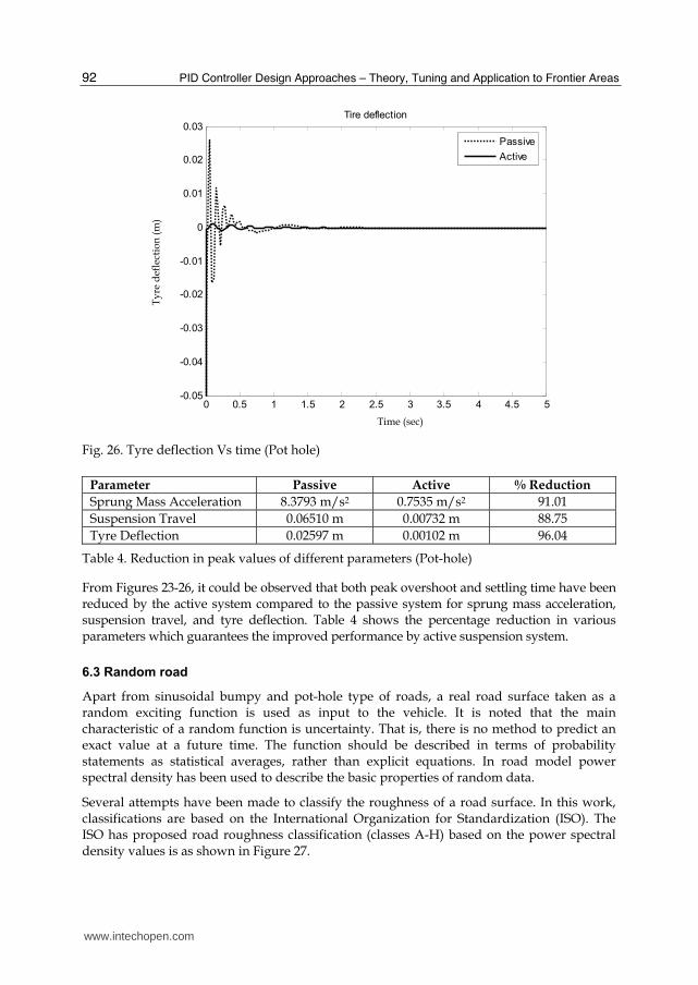
Fig. 26. Tyre deflection Vs time (Pot hole)
Parameter Passive Active % Reduction
Sprung Mass Acceleration 8.3793 m/s2 0.7535 m/s2 91.01
Suspension Travel 0.06510 m 0.00732 m 88.75
Tyre Deflection 0.02597 m 0.00102 m 96.04
Table 4. Reduction in peak values of different parameters (Pot-hole)
From Figures 23-26, it could be observed that both peak overshoot and settling time have been reduced by the active system compared to the passive system for sprung mass acceleration, suspension travel, and tyre deflection. Table 4 shows the percentage reduction in various parameters which guarantees the improved performance by active suspension system.
6.3 Random road
Apart from sinusoidal bumpy and pot-hole type of roads, a real road surface taken as a random exciting function is used as input to the vehicle. It is noted that the main characteristic of a random function is uncertainty. That is, there is no method to predict an exact value at a future time. The function should be described in terms of probability statements as statistical averages, rather than explicit equations. In road model power spectral density has been used to describe the basic properties of random data.
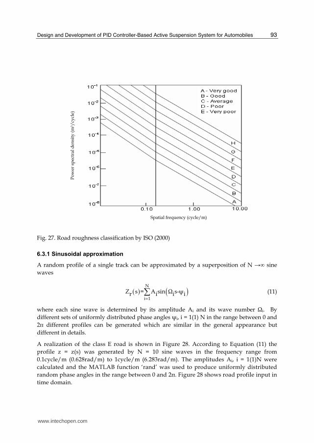
Several attempts have been made to classify the roughness of a road surface. In this work, classifications are based on the International Organization for Standardization (ISO). The ISO has proposed road roughness classification (classes A-H) based on the power spectral density values is as shown in Figure 27.
Ty
re d
efle
ctio
n (
m)
Time (sec)
0 0.5 1 1.5 2 2.5 3 3.5 4 4.5 5-0.05
-0.04
-0.03
-0.02
-0.01
0
0.01
0.02
0.03Tire deflection
Passive
Active
www.intechopen.com
Design and Development of PID Controller-Based Active Suspension System for Automobiles
93
Fig. 27. Road roughness classification by ISO (2000)
6.3.1 Sinusoidal approximation
A random profile of a single track can be approximated by a superposition of N →∞ sine
waves
N
i 1
Z s = A sin Ω s-┰r i i i (11)
where each sine wave is determined by its amplitude Ai and its wave number Ωi. By
different sets of uniformly distributed phase angles ┰i, i = 1(1) N in the range between 0 and
2π different profiles can be generated which are similar in the general appearance but
different in details.
A realization of the class E road is shown in Figure 28. According to Equation (11) the
profile z = z(s) was generated by N = 10 sine waves in the frequency range from
0.1cycle/m (0.628rad/m) to 1cycle/m (6.283rad/m). The amplitudes Ai, i = 1(1)N were
calculated and the MATLAB function ‘rand’ was used to produce uniformly distributed
random phase angles in the range between 0 and 2π. Figure 28 shows road profile input in
time domain.
Spatial frequency (cycle/m)
Po
wer
sp
ectr
al d
ensi
ty (
m3/
cycl
e)
www.intechopen.com
PID Controller Design Approaches – Theory, Tuning and Application to Frontier Areas
94
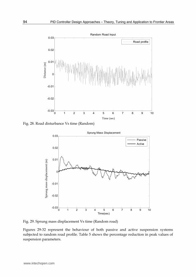
Fig. 28. Road disturbance Vs time (Random)
0 1 2 3 4 5 6 7 8 9 10-0.03
-0.02
-0.01
0
0.01
0.02
0.03
Time(sec)
Spru
ng M
ass D
ispla
cem
ent(
m)
Sprung Mass Displacement
Passive
Active
Fig. 29. Sprung mass displacement Vs time (Random road)
Figures 29-32 represent the behaviour of both passive and active suspension systems
subjected to random road profile. Table 5 shows the percentage reduction in peak values of
suspension parameters.
Dis
tan
ce (
m)
Time (sec)
0 1 2 3 4 5 6 7 8 9 10-0.03
-0.02
-0.01
0
0.01
0.02
0.03Random Road Input
Road profile
Sp
run
g m
ass
dis
pla
cem
ent
(m)
www.intechopen.com
Design and Development of PID Controller-Based Active Suspension System for Automobiles
95
0 1 2 3 4 5 6 7 8 9 10-4
-3
-2
-1
0
1
2
3
4
Time(sec)
Accele
ration
(m/s
ec
2)
Acceleration
Passive
Active
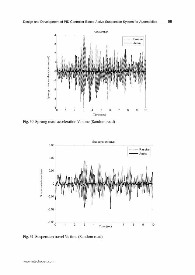
Fig. 30. Sprung mass acceleration Vs time (Random road)
0 1 2 3 4 5 6 7 8 9 10-0.03
-0.02
-0.01
0
0.01
0.02
0.03
Time(sec)
Suspensio
n t
ravel(m
)
Suspension travel
Passive
Active
Fig. 31. Suspension travel Vs time (Random road)
Sp
run
g m
ass
acce
lera
tio
n (
m/
sec2
)
Su
spen
sio
n t
rav
el (
m)
Time (sec)
Time (sec)
www.intechopen.com
PID Controller Design Approaches – Theory, Tuning and Application to Frontier Areas
96
0 1 2 3 4 5 6 7 8 9 10-0.03
-0.02
-0.01
0
0.01
0.02
0.03
Time(sec)
Tire d
eflection(m
)
Tire deflection
Passive
Active
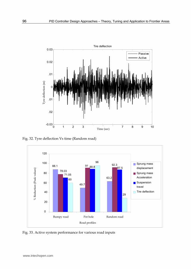
Fig. 32. Tyre deflection Vs time (Random road)
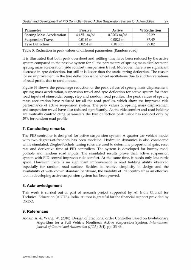
Fig. 33. Active system performance for various road inputs
88.1
49.7
63.2
78.03
91 92.3
71.05
88.8 87.5
60
96
29
0
20
40
60
80
100
120
Bumpy road Pot hole Random road
Road profiles
% R
edu
ctio
n (
Pea
k v
alu
es)
Sprung mass
displacement
Sprung mass
Acceleration
Suspension
travel
Tire deflection
Ty
re d
efle
ctio
n (
m)
Time (sec)
www.intechopen.com
Design and Development of PID Controller-Based Active Suspension System for Automobiles
97
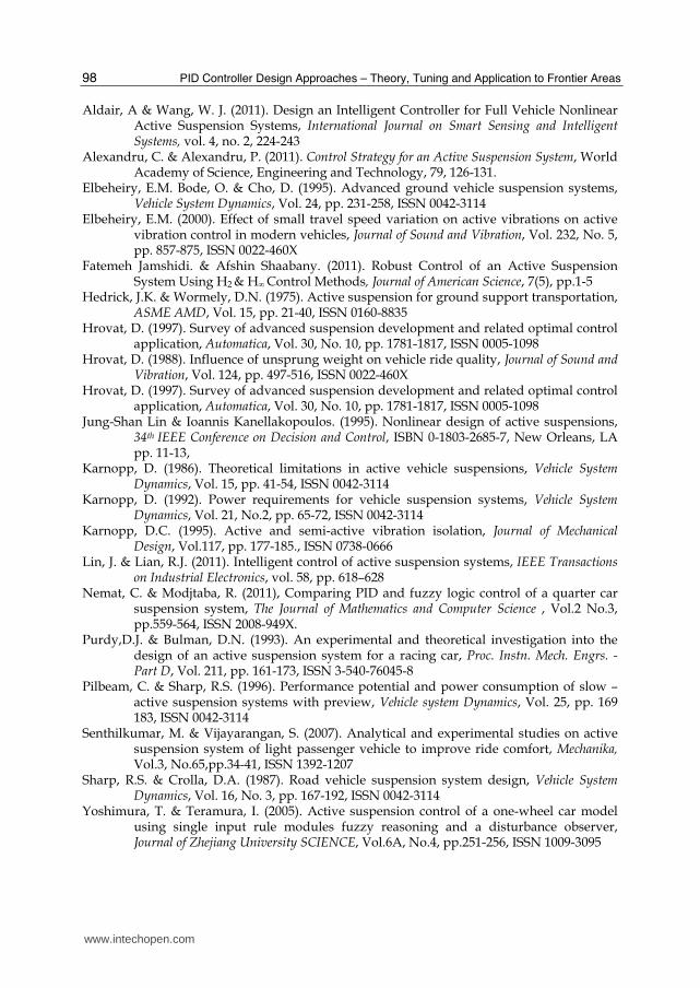
Parameter Passive Active % Reduction
Sprung Mass Acceleration 4.1551 m/s2 0.3203 m/s2 92.29
Suspension Travel 0.0195 m 0.0024 m 87.45
Tyre Deflection 0.0254 m 0.018 m 29.02
Table 5. Reduction in peak values of different parameters (Random road)
It is illustrated that both peak overshoot and settling time have been reduced by the active system compared to the passive system for all the parameters of sprung mass displacement, sprung mass acceleration (ride comfort), suspension travel. Moreover, there is no significant decrease in tyre deflection, but still it is lesser than the static spring deflection. The reason for no improvement in the tyre deflection is the wheel oscillations due to sudden variations of road profile due to randomness.
Figure 33 shows the percentage reduction of the peak values of sprung mass displacement, sprung mass acceleration, suspension travel and tyre deflection for active system for three road inputs of sinusoidal bump, step and random road profiles. The peak values of sprung mass acceleration have reduced for all the road profiles, which show the improved ride performance of active suspension system. The peak values of sprung mass displacement and suspension travel have also reduced significantly. As the ride comfort and road holding are mutually contradicting parameters the tyre deflection peak value has reduced only by 29% for random road profile.
7. Concluding remarks
The PID controller is designed for active suspension system. A quarter car vehicle model with two-degrees-of-freedom has been modeled. Hydraulic dynamics is also considered while simulated. Ziegler-Nichols tuning rules are used to determine proportional gain, reset rate and derivative time of PID controllers. The system is developed for bumpy road, pothole and random road inputs. The simulated results prove that, active suspension system with PID control improves ride comfort. At the same time, it needs only less rattle space. However, there is no significant improvement in road holding ability observed especially for random road surface. Besides its relative simplicity in design and the availability of well-known standard hardware, the viability of PID controller as an effective tool in developing active suspension system has been proved.
8. Acknowledgement
This work is carried out as part of research project supported by All India Council for Technical Education (AICTE), India. Author is grateful for the financial support provided by DRDO.
9. References
Aldair, A. &. Wang, W. (2010). Design of Fractional order Controller Based on Evolutionary Algorithm for a Full Vehicle Nonlinear Active Suspension System, International journal of Control and Automation (IJCA), 3(4). pp. 33-46.
www.intechopen.com
PID Controller Design Approaches – Theory, Tuning and Application to Frontier Areas
98
Aldair, A & Wang, W. J. (2011). Design an Intelligent Controller for Full Vehicle Nonlinear Active Suspension Systems, International Journal on Smart Sensing and Intelligent Systems, vol. 4, no. 2, 224-243
Alexandru, C. & Alexandru, P. (2011). Control Strategy for an Active Suspension System, World Academy of Science, Engineering and Technology, 79, 126-131.
Elbeheiry, E.M. Bode, O. & Cho, D. (1995). Advanced ground vehicle suspension systems, Vehicle System Dynamics, Vol. 24, pp. 231-258, ISSN 0042-3114
Elbeheiry, E.M. (2000). Effect of small travel speed variation on active vibrations on active vibration control in modern vehicles, Journal of Sound and Vibration, Vol. 232, No. 5, pp. 857-875, ISSN 0022-460X
Fatemeh Jamshidi. & Afshin Shaabany. (2011). Robust Control of an Active Suspension System Using H2 & H∞ Control Methods, Journal of American Science, 7(5), pp.1-5
Hedrick, J.K. & Wormely, D.N. (1975). Active suspension for ground support transportation, ASME AMD, Vol. 15, pp. 21-40, ISSN 0160-8835
Hrovat, D. (1997). Survey of advanced suspension development and related optimal control application, Automatica, Vol. 30, No. 10, pp. 1781-1817, ISSN 0005-1098
Hrovat, D. (1988). Influence of unsprung weight on vehicle ride quality, Journal of Sound and Vibration, Vol. 124, pp. 497-516, ISSN 0022-460X
Hrovat, D. (1997). Survey of advanced suspension development and related optimal control application, Automatica, Vol. 30, No. 10, pp. 1781-1817, ISSN 0005-1098
Jung-Shan Lin & Ioannis Kanellakopoulos. (1995). Nonlinear design of active suspensions, 34th IEEE Conference on Decision and Control, ISBN 0-1803-2685-7, New Orleans, LA pp. 11-13,
Karnopp, D. (1986). Theoretical limitations in active vehicle suspensions, Vehicle System Dynamics, Vol. 15, pp. 41-54, ISSN 0042-3114
Karnopp, D. (1992). Power requirements for vehicle suspension systems, Vehicle System Dynamics, Vol. 21, No.2, pp. 65-72, ISSN 0042-3114
Karnopp, D.C. (1995). Active and semi-active vibration isolation, Journal of Mechanical Design, Vol.117, pp. 177-185., ISSN 0738-0666
Lin, J. & Lian, R.J. (2011). Intelligent control of active suspension systems, IEEE Transactions on Industrial Electronics, vol. 58, pp. 618–628
Nemat, C. & Modjtaba, R. (2011), Comparing PID and fuzzy logic control of a quarter car suspension system, The Journal of Mathematics and Computer Science , Vol.2 No.3, pp.559-564, ISSN 2008-949X.
Purdy,D.J. & Bulman, D.N. (1993). An experimental and theoretical investigation into the design of an active suspension system for a racing car, Proc. Instn. Mech. Engrs. - Part D, Vol. 211, pp. 161-173, ISSN 3-540-76045-8
Pilbeam, C. & Sharp, R.S. (1996). Performance potential and power consumption of slow – active suspension systems with preview, Vehicle system Dynamics, Vol. 25, pp. 169 183, ISSN 0042-3114
Senthilkumar, M. & Vijayarangan, S. (2007). Analytical and experimental studies on active suspension system of light passenger vehicle to improve ride comfort, Mechanika, Vol.3, No.65,pp.34-41, ISSN 1392-1207
Sharp, R.S. & Crolla, D.A. (1987). Road vehicle suspension system design, Vehicle System Dynamics, Vol. 16, No. 3, pp. 167-192, ISSN 0042-3114
Yoshimura, T. & Teramura, I. (2005). Active suspension control of a one-wheel car model using single input rule modules fuzzy reasoning and a disturbance observer, Journal of Zhejiang University SCIENCE, Vol.6A, No.4, pp.251-256, ISSN 1009-3095
www.intechopen.com
PID Controller Design Approaches - Theory, Tuning andApplication to Frontier AreasEdited by Dr. Marialena Vagia
ISBN 978-953-51-0405-6Hard cover, 286 pagesPublisher InTechPublished online 28, March, 2012Published in print edition March, 2012
InTech EuropeUniversity Campus STeP Ri Slavka Krautzeka 83/A 51000 Rijeka, Croatia Phone: +385 (51) 770 447 Fax: +385 (51) 686 166www.intechopen.com
InTech ChinaUnit 405, Office Block, Hotel Equatorial Shanghai No.65, Yan An Road (West), Shanghai, 200040, China
Phone: +86-21-62489820 Fax: +86-21-62489821
First placed on the market in 1939, the design of PID controllers remains a challenging area that requires newapproaches to solving PID tuning problems while capturing the effects of noise and process variations. Theaugmented complexity of modern applications concerning areas like automotive applications, microsystemstechnology, pneumatic mechanisms, dc motors, industry processes, require controllers that incorporate intotheir design important characteristics of the systems. These characteristics include but are not limited to:model uncertainties, system's nonlinearities, time delays, disturbance rejection requirements and performancecriteria. The scope of this book is to propose different PID controllers designs for numerous moderntechnology applications in order to cover the needs of an audience including researchers, scholars andprofessionals who are interested in advances in PID controllers and related topics.
How to referenceIn order to correctly reference this scholarly work, feel free to copy and paste the following:
Senthilkumar Mouleeswaran (2012). Design and Development of PID Controller-Based Active SuspensionSystem for Automobiles, PID Controller Design Approaches - Theory, Tuning and Application to FrontierAreas, Dr. Marialena Vagia (Ed.), ISBN: 978-953-51-0405-6, InTech, Available from:http://www.intechopen.com/books/pid-controller-design-approaches-theory-tuning-and-application-to-frontier-areas/design-and-development-of-active-suspension-system-using-pid-controller