Embed Size (px)
Citation preview
DESIGN AND DEVELOPMENT OF DIGITAL PID CONTROLLER TO CONTROL SPEED OF PERMANENT MAGNET DC MOTOR FOR PCB DRILLING
OPERATION
MUHAMMAD ALTAF BIN A JALIL
A report submitted in partial fulfillment of the
requirement for the award of the degree of
Bachelor of Mechanical Engineering
Faculty of Mechanical Engineering
Universiti Malaysia Pahang
NOVEMBER 2007
ABSTRACT
Every mechanical system in this world will always be affected by the
environment that prevents it from working as wanted. Normally, there are always has
differences between experiment result and actual result. Drilling operation is one
example of a mechanical system that is always been effected by environment during
actual process. During drilling operation, the speed of the motor that rotate the cutting
tool will tend to be slower from the initial speed due to the friction causes when the
cutting tool makes contact with the workpiece. The reduction of speed during drilling
operation will decrease the performance of the drilling operation and make it less
efficient. In order to solve this problem, a controller can be use to control the speed of
the motor. Digital PD controller is one of the examples. Using Digital P11), it can
eliminate steady-state error and improve transient response of the system response of the
motor. The theory is, when the speed of the motor become decreasing during drilling
operation, the Digital PD will detect the error and will tried to eliminate it. To
eliminate the error, the Digital PD will increase the voltage supplied to the motor to
maintain the speed of the motor. When the speed of the motor is maintained, the
performance of the drilling operation can also be maintain and become more efficient.
In
ABSTRAK
Setiap sistem mekanikal di dalain dunia akan selalu terkesan dengan persekitaran
yang akan menghalang sistem tersebut beroperasi seperti yang dikehendaki. Selalunya
terdapat perbezaan di antara keputusan daripada eksperimen dengan keputusan yang
sebenar. Salah satu contoh sistem mekanikal yang sering terkesan dengan persekitaran
semasa operasi sebenar adalah proses menebuk lubang. Semasa operasi menebuk
lubang, kelajuan motor yang memutarkan mata alat akan berkurangan disebabkan oleh
geseran yang terhasil daripada pertemuan antara permukaan mata alat dengan bahan
kerja. Pengurangan kelajuan mi akan menyebabkan proses menebuk lubang tersebut
kurang efisien. Untuk mengatasi masalah mi, satu sistem kawalan boleh digunakan
untuk megawal kelajuan motor tersebut. Salah satu contoh sistem kawalan yang boleh
digunakan adalah PID Digital. Dengan menggunakan PID Digital, kesilapan tahap stabil
dapat dihilangkan dan respons transisi untuk sistem motor tersebut dapat dipercepatkan.
Secara teori, semasa proses menebuk lubang dijalankan, kelajuan motor akan
berkurangan. PID Digital akan mengesan pengurangan mi dan akan menghilangkan
perbezaan diantara kelajuan asal dengan kelajuan semasa. Untuk itu, PB) Digital akan
meningkatkan voltan yang dibekalkan kepada motor untuk memastikan kelajuan motor
sentiasa setara dengan kelajuan asal. Apabila kelajuan motor berjaya di setarakan, mutu
proses menebuk lubang juga akan dapat di setarakan dan efisiensi proses akan
meningkat.
A
TABLE OF CONTENTS
TITLE I
DECLARATION
II
DEDICATION
111
ACKNOWLEDGEMENT
IV
ABSTRACT
V
ABSTRAK
VI
TABLE OF CONTENTS
VII
LIST OF TABLES x
LIST OF FIGURES xi
LIST OF SYMBOLS
XII'
LIST OF APPENDICES
Xiv
VII
CHAPTER
TITLE
PAGE
1
INTRODUCTION
I
1.1 Project Background
I
1.2 Project Problem Statement
3
1.3 Project Objectives 4
1.4 Project Scopes 4
2 LITERATURE REVIEW
6
2.1 Drilling Machines 6
2.2 DC Motor 9
2.3 Control System 13
2.4 Control System Controller 17
VIII
2.4.1 Type of Controller 18
2.4.2 PID Controller 18
2.5 Sensors 19
2.5.1 Tachometer 20
2.5.2 Encoder 21
2.6 Feedback Control Type 22
2.6.1 Sampled-Data System 22
2.6.2 Phase-Locked Control 23
2.7 Driver Techniques 24
2.7.1 Continuous Driver 24
2.7.2 Pulse-Width Modulation 25
3 METHODOLOGY 27
3.0 Introduction 27
3.1 Building Digital P11) Hardware Circuit 28
3.2 Creating the Program for the Digital PD 28
3.3 Calculating The Mathematical Model for The DC
Motor. 29
3.4 Digital PID Tuning 30
3.5 Test The System Performance with Digital PID
Compensated During Drilling The PCB. 32
4 RESULTS AND DISCUSSION 33
4.0 Introduction 33
4.1 Building The Digital P11) Hardware 34
4.1.1 The Programmable Integrated Circuit (PlC) 35
4.1.2 The Digital to Analog Converter (DAC) 38
4.1.3 DC Motor Driver 40
4.1.4 The Encoder and the Light Sensor 42
4.2 The Digital PID C Program 43
4.3 The Mathematical Model of the DC Motor 45
Ix
4.4 The PD Tuning 49
4.5 The System Performance with Digital PD
Compensated During Drilling the PCB 55
5 CONCLUSION 56
5.1 Conclusion 56
5.2 Recommendation 57
REFERENCES 58
Appendices A-G 59-67
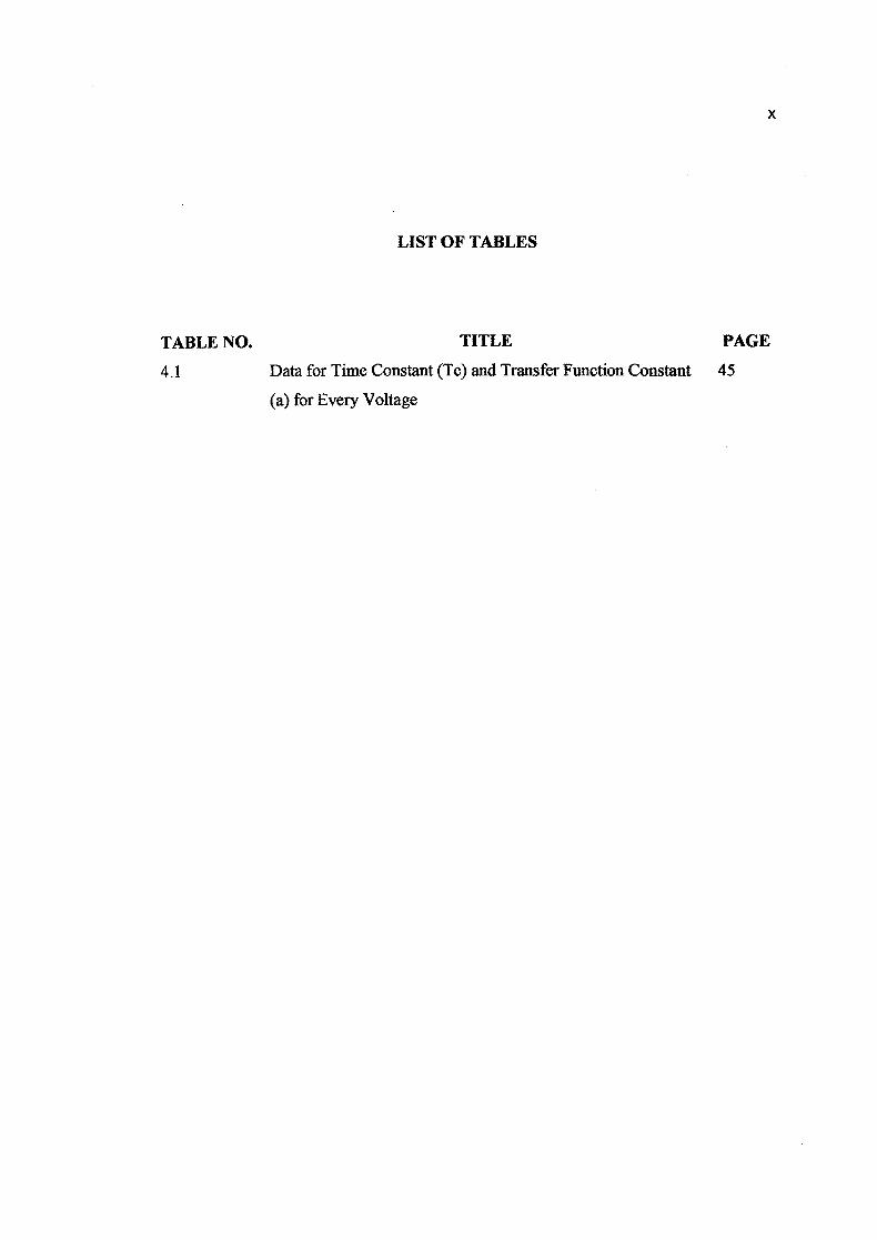
LIST OF TABLES
TABLE NO. TITLE PAGE
4.1 Data for Time Constant (Tc) and Transfer Function Constant 45
(a) for Every Voltage
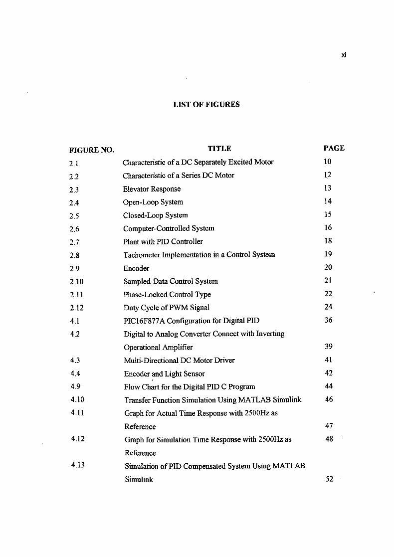
LIST OF FIGURES
FIGURE NO. TITLE PAGE
2.1 Characteristic of a DC Separately Excited Motor 10
2.2 Characteristic of a Series DC Motor 12
2.3 Elevator Response 13
2.4 Open-Loop System 14
2.5 Closed-Loop System 15
2.6 Computer-Controlled System 16
2.7 Plant with PID Controller 18
2.8 Tachometer Implementation in a Control System 19
2.9 Encoder 20
2.10 Sampled-Data Control System 21
2.11 Phase-Locked Control Type 22
2.12 Duty Cycle of PWM Signal 24
4.1 P1C16F877A Configuration for Digital PID 36
4.2 Digital to Analog Converter Connect with Inverting
Operational Amplifier 39
4.3 Multi-Directional DC Motor Driver 41
4.4 Encoder and Light Sensor 42
4.9 Flow Chart for the Digital PU) C Program 44
4.10 Transfer Function Simulation Using MATLAB Simulink 46
4.11 Graph for Actual Time Response with 2500Hz as
Reference
4.12 Graph for Simulation Time Response with 250011z as 48
Reference
4.13 Simulation of PID Compensated System Using MATLAB
Simulmk 52
XI
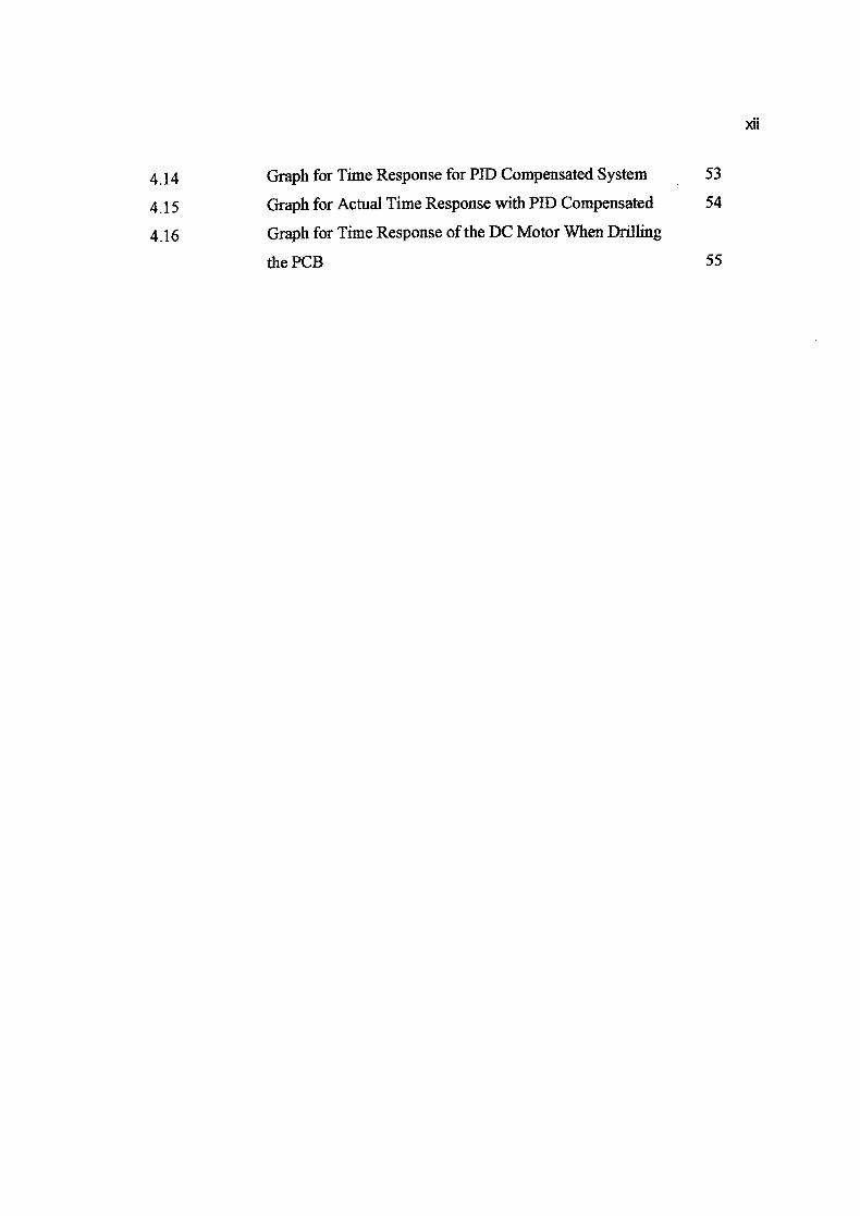
xfl
4.14 Graph for Time Response for PD Compensated System 53
4.15 Graph for Actual Time Response with PID Compensated 54
4.16 Graph for Time Response of the DC Motor When Drilling
the PCB 55
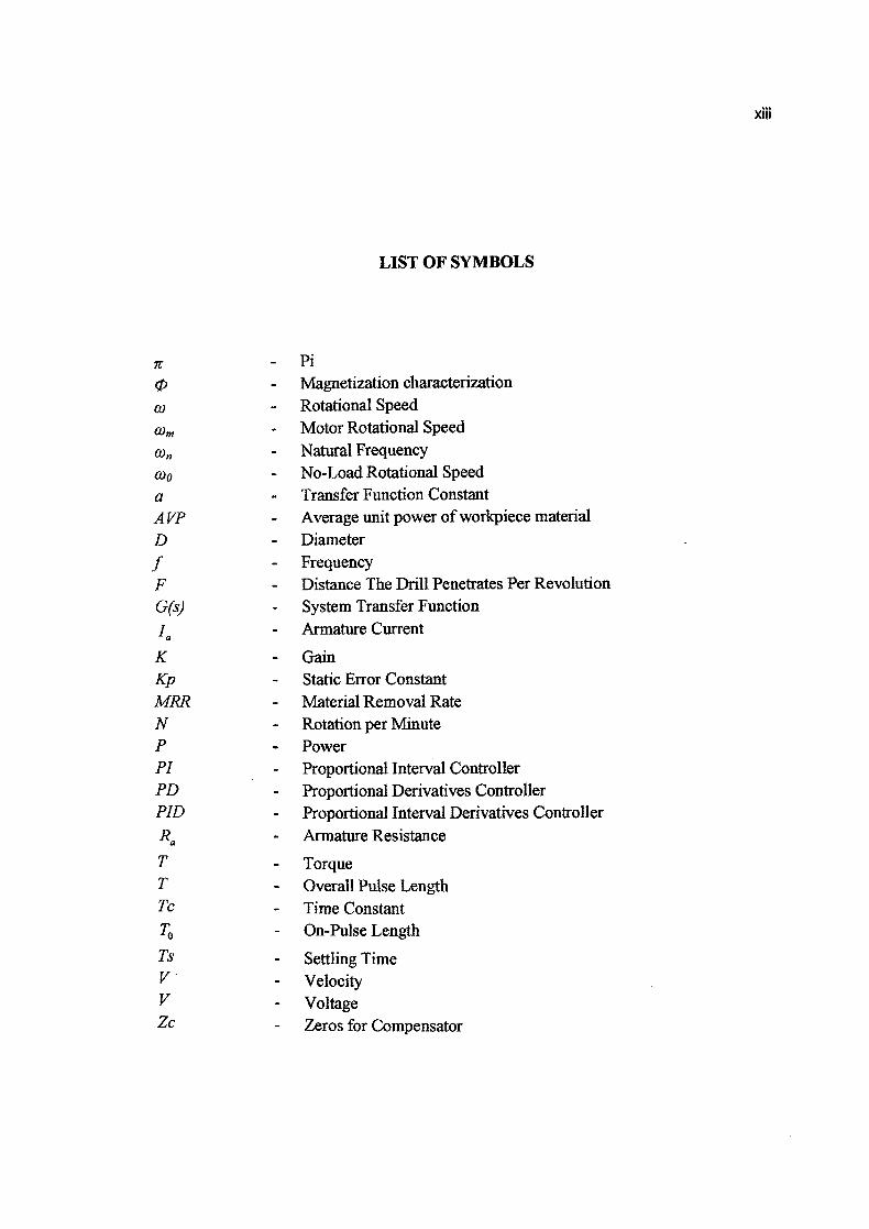
LIST OF SYMBOLS
it - Pi ç/) - Magnetization characterization
co - Rotational Speed
Wm - Motor Rotational Speed - Natural Frequency
(1)0 - No-Load Rotational Speed a - Transfer Function Constant A VP - Average unit power of workpiece material D - Diameter
f - Frequency F - Distance The Drill Penetrates Per Revolution G(s) - System Transfer Function
1. - Armature Current
K - Gain Kp - Static Error Constant MRR - Material Removal Rate N - Rotation per Minute P - Power P1' - Proportional Interval Controller PD - Proportional Derivatives Controller PID - Proportional Interval Derivatives Controller R. - Armature Resistance
T - Torque T - Overall Pulse Length Tc - Time Constant
TO - On-Pulse Length
Ts - Settling Time V - Velocity V - Voltage Zc - Zeros for Compensator
XIII
LIST OF APPENDICES
APPENDIX TITLE PAGE
A Methodology Flowchart 59
B Digital P11) Circuit Schematic Diagram 60
C C Program For Digital PID 61
D Root Locus For Actual DC Motor System 64
E Root Locus For DC Motor System With Digital PD
Compensated 65
F Gantt Chart For Final Year Project 1 66
G Gantt Chart For Final Year Project 2 67
xiv
CHAPTER 1
INTRODUCTION
1.1 Project Background
Drilling machines is the most common machine use to make a hole and it is
widely use in the industry [5]. Drilling machines comes in a lot of type depending on its
usage. The types of the drilling machines are Drill Press type, Bench-Type are Radial
Drill. The Drill Press type is the common type. Bench type is for drilling small
diameter holes and Radial Drill use to drill large diameter of holes [5].
The drilling machine performance is based on some criteria which are; how large
of the work piece of the machine can handle, how many holes it can drill at one time and
how accurate the holes can be drilled regarding its position and size.
Drilling machine comes in 9 parts (regarding the drill press type) which are fixed
head, spindle, adjustable head, spindle, chuck, table, base, hand and column. The motor
that rotate the drill is installed in the fixed head and it is the most important part in the
drilling machines. It is because the motor will be effecting how fast the drill can rotate.
2
Electric motor comes in 2 type which are DC motor and AC motor. Different
between DC motor and AC motor is the current use to rotate the motor. DC motor use
direct current and AC motor use alternate current. The DC motor operates using an
electromagnetic field that occurs when the wire coil inside the motor is given an electric
current. The magnetic field of a permanent magnet in the DC motor will collide with the
electromagnetic field to create a rotation for the motor. Basically, the rotation of the DC
motor is based on the electrical current supplied to the motor. Zero volts mean zero
speed and maximum volts means maximum speed.
To control the speed of the motor, Proportional Integral Derivatives (PID)
controller can be use in the drilling machines control system. The PB) controller is an
active controller which eliminates steady-state error and improves the system transient
response [6].
There are two types of controller; analog and digital [6]. Analog controller is
simple and cheaper than digital controller. The digital control system use a computer to
supervise and control the system which made the system more reliable in handling varies
parameters and has immunity to noise [6].
In this project, an efficient and reliable PB) will be design and build based on
digital control system to control the speed of the DC motor in the drilling machine.
3
1.2 Project Problem Statement
The problem in this project is to control the speed of the DC motor. During the
drilling process, when the drill is press onto the work piece to create holes, the speed of
the motor tends to decrease slightly. This phenomenon occurs because there is friction
force between the drill and the work piece due to the load given.
By the definition, friction is defined as the resistance to relative motion. Motion
has connection with speed, so the higher the friction, the higher the resistance to the
motion and decreasing in speed. The decreased of the speed will affect the speed the
feed rate of the drilling process and there will be an error for the motor output.
Normally user will calculate the speed needed for the drill machine theoretically before
the drilling process [5]. Then, the drilling machine speed is set to a speed that larger
than the calculated speed. This process required estimation by the user to get the exact
speed for the drilling machine which is obviously impossible.
The problem for this project is that to correct the error of the speed of the motor
cause by the friction forces during the drilling process.
4
1.3 Project Objectives
i. To build a digital system PU) controller for the DC motor speed control.
ii. To make a C programming code for the digital PU)
iii. To use PCB as the test material for the drilling operation.
1.4 Project Scopes
First, this project will be focusing on building a digital P1]) controller as the
controller in the control system. Even there are other more high performances
controllers that can be use like fuzzy-logic, this project only based on designing a digital
P1]) controller to correct the error for the drilling process.
The only parameter that will be study is only the speed of the motor before,
during and after the drilling process. Any other parameter such as accuracy and position
of the drill will not be discussed.
DC motor comes in a large variety of type depending on its usage such as; Series
DC motor, Separately Excited DC motor and Permanent Magnet DC motor. Permanent
Magnet DC motor is the type of DC motor that will be use in this project.
5
There are two types of control system that can be use which is digital system and
analog system. In this project, the type of control structure that will be implements is
the digital control system type structure.
In the system structure, there are two type of structure form which is open-loop
system and closed-loop system. A closed-loop system will be use for this project.
In the control system, the feedback control type come in two which are; sampled
data feedback system and phase locked feedback system. In this project a phase locked
feedback system will be apply for the feedback control type.
The sensor is a device to detect any changes between the input and output of the
system. Sensor can be a tachometer or encoder. The sensor that will be use in this
project is encoder.
The material use for drilling in this project is PCB. This Project only focus on to
study how to control speed of the DC motor when use to drill the PCB. Also the use of
the PCB is because this project focus is for light drilling process.
CHAPTER 2
LITERATURE REVIEW
2.1 Drilling Machines
In fabricating process, Holemaking is one of the important processes to make a
hole. Holes are use to put a fastener for joining, or to insert shaft [5]. Drilling is the
most common process to make holes [5]. There are a lot of drilling machine type use in
industry based on its usage and capabilities. The most common type is the Drill Press
type [5]. Other than that is the Bench-Type use for light drilling to drill small diameter
holes and Radial Drill use to drill large diameter holes. The drilling machines are design
to have an adjustable drill speed to suit various kinds of drill and workpiece [S].
There are a lot of type of drill use in drilling processes which are Twist, Straight-
Flute, Spade, Gun Drill, Drill with Bozel Carbide Tip and Drill with Indexable Carbide
Insert. The Drill also has a high length to diameter ratio which made it easier to drill
deeper holes [5]. Other than drilling, a drilling machines also capable to do other
process such as Tapping, Reaming and Small Diameter Boring [5]. For the drilling
process, the workpiece is located on an adjustable table fix with a holder or vise to
secure it. The drill is lower manually by hand or automatically by using press feed.
Drilling a workpiece manually need a higher operator skill.
7
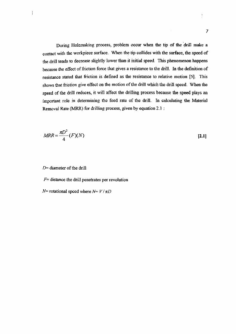
During Holemaking process, problem occur when the tip of the drill make a
contact with the workpiece surface. When the tip collides with the surface, the speed of
the drill tends to decrease slightly lower than it initial speed. This phenomenon happens
because the effect of friction force that gives a resistance to the drill. In the definition of
resistance stated that friction is defined as the resistance to relative motion [5]. This
shows that friction give effect on the motion of the drill which the drill speed. When the
speed of the drill reduces, it will affect the drilling process because the speed plays an
important role in determining the feed rate of the drill. In calculating the Material
Removal Rate (MRR) for drilling process, given by equation 2.1
MRR= ,zD2
(F)(N)
[2.11
D= diameter of the drill
F= distance the drill penetrates per revolution
N= rotational speed where N= VI rcD
8
So, it is clear that speed give impact on the material removal rate for the drilling.
Reduce of the speed mean reducing its MRR too. When the MRR reduces, it will affect
the performance of the drilling process and make it less efficient and less power. This
effect can be seen by the power of the drilling machine given by equation 2.2:
P = MRRXAVP
[2.2J
P = Power
MRR = Material Removal Rate
A VP = average unit power of workpiece material
Other than that, speed also affects the Torque on the drill. In calculating torque
for the drilling process, power and rotational speed is the main criteria in determining
the torque of the drill. From the equation of torque for rotational speed in the equation
2.3:
T=Co
[2.3J
= rotational speed of the drill.
P = Power
T = Torque
9
From equation 2.1, 2.2, and 2.3, it can be concluded that the criteria in
determining the performance of the drilling process required the MRR, speed, Torque,
diameter of drill, and distance of the drill penetrates per revolution.
In this project, the criteria that will be manipulated to improve the performance
of the drilling process are speed. The workpiece to be drill will be PCB using a light
drilling process.
2.2 DC Motor
In a traditional drilling process, an electrical motor is use to rotate the drill to
make a hole at the workpiece. An electrical motor is a device that converts electrical
energy into mechanical energy [7]. During the operation of an electrical motor, the
electrical energy will be converted into a rotary mechanical energy.
There are two types of electrical motor which are DC motor and AC motor.
Basically DC motor is an electrical motor that use direct current to operate while AC
motor use alternating current to operate. The basic principle for the motor is the same
for both type of motor. It works when an electromagnet from the coil in the motor
collide with the field magnet in the motor. As remember about the magnet law that
when both same pole are facing, the magnet will be rejecting each other. In the motor,
the situation is just the same, the electromagnetic field that occur when the coil in the
motor is given an electrical current collide with the field magnet in the motor, both
magnet will be pushing each other and create a torque for the motor to rotate.
10
In a DC motor, there are two main parts that keep the motor running which are
the stator and rotor. Stator is always being the field magnet that is fixed in the motor [7]
and rotor is movable parts that create torque while the motor operate. Normally a rotor
can be in a cylindrical or disc-shaped. The other part is the commutator. A commutator
is a rotary switch that reverses the current supplied to the motor at each cycle [3] to
make sure that the motor is rotating at a same direction during the operation.
There are a lot of types of DC motor which include Permanent Magnet DC
motor, Separately Excited DC motor, Series DC motor. These all types are use in
different application based on each motor characteristic.
Permanent magnet DC motor as like its name is a DC motor that uses a
permanent magnet as the stator. A suitable permanent magnet is installed in the motor
as a field excitation. The type of permanent magnet can be ferrites or rare earth
depended on the motor application. A ferrites permanent magnet normally is low in cost
but come in a bulky size and low retentivity. A rare earth permanent magnet has high
retentivity which allows large reduction but it also very expensive.
By the use of the permanent magnet in the DC motor, it can eliminate field
copper loss that needed for field supply. The permanent magnet DC motor is more
efficient, reliable, sturdy and compact because the field fluxes remain constant for all
loads. It is also more linear to speed torque character. The disadvantage of permanent
magnet DC motor is that its speed can't be controlled when above the base speed. The
application of permanent magnet DC motor is at drilling machine, forklift truck and
wheel chair.
Speed Torque Graph Torque-Current Graph
COrn I
I 'a
I
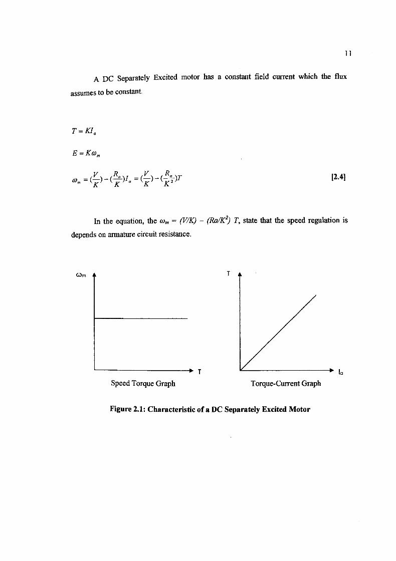
A DC Separately Excited motor has a constant field current which the flux
assumes to be constant.
T = KIa
E=K(üm
VR V (---)T = -a = () - 2
In the equation, the O.)m = (V/K) - (Ra/K2) T, state that the speed regulation is
depends on armature circuit resistance.
12.41
Figure 2.1: Characteristic of a DC Separately Excited Motor
12
The Figure 2.1 shows the behavior of the DC Separately Excited motor when it
operates. The no-load COo is determined by armature voltage and field excitation since
we cannot determine it from the graph. The most application of the DC Separately
Excited motor is that in an application that need a good speed regulation and adjustable
speed.
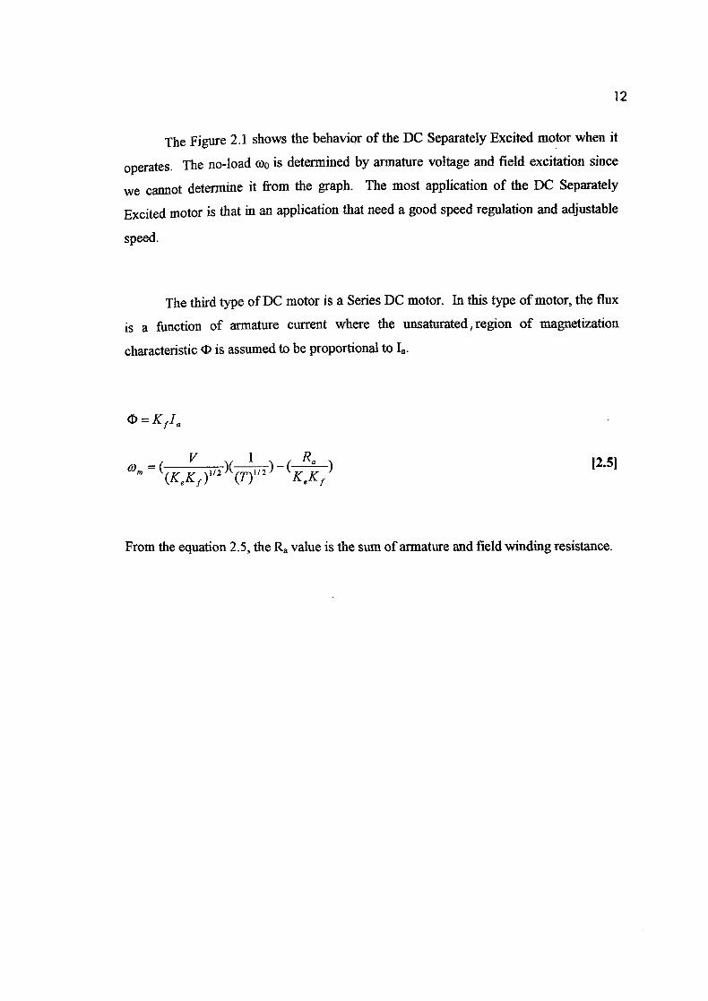
The third type of DC motor is a Series DC motor. In this type of motor, the flux
is a function of armature current where the unsaturated, region of magnetization
characteristic t is assumed to be proportional to 'a
= K1I
Om=()(_1 Ra
112 112
(.K,, Kf
From the equation 2.5, the Ra value is the sum of armature and field winding resistance.
[2.5J
13
Torque-Current Graph
T
(A)m
Speed Torque Graph
I
'a
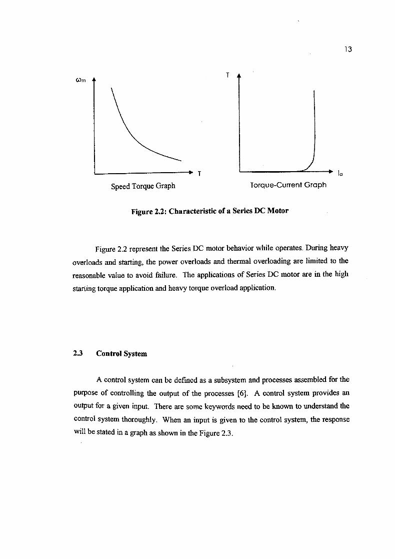
Figure 2.2: Characteristic of a Series DC Motor
Figure 2.2 represent the Series DC motor behavior while operates. During heavy
overloads and starting, the power overloads and thermal overloading are limited to the
reasonable value to avoid failure. The applications of Series DC motor are in the high
starting torque application and heavy torque overload application.
2.3 Control System
A control system can be defined as a subsystem and processes assembled for the
purpose of controlling the output of the processes [6]. A control system provides an
output for a given input. There are some keywords need to be known to understand the
control system thoroughly. When an input is given to the control system, the response
will be stated in a graph as shown in the Figure 2.3.