Embed Size (px)
Citation preview

materials
Article
Design and Development of an E-Textile Mat for Assuring theComfort of Bedridden Persons
Daniela Sofronova 1, Radostina A. Angelova 1,* and Yavor Sofronov 2
Citation: Sofronova, D.; Angelova,
R.A.; Sofronov, Y. Design and
Development of an E-Textile Mat for
Assuring the Comfort of Bedridden
Persons. Materials 2021, 14, 5437.
https://doi.org/10.3390/ma14185437
Academic Editor: Barbara Simoncic
Received: 12 August 2021
Accepted: 17 September 2021
Published: 20 September 2021
Publisher’s Note: MDPI stays neutral
with regard to jurisdictional claims in
published maps and institutional affil-
iations.
Copyright: © 2021 by the authors.
Licensee MDPI, Basel, Switzerland.
This article is an open access article
distributed under the terms and
conditions of the Creative Commons
Attribution (CC BY) license (https://
creativecommons.org/licenses/by/
4.0/).
1 Centre of Competence MIRACle—Mechatronics, Innovation, Robotics, Automation, Clean Technologies,Laboratory “Intelligent Mechatronic Solutions in the Field of Textiles and Clothing”, Technical University ofSofia, 1000 Sofia, Bulgaria; [email protected]
2 Laboratory “CAD/CAM/CAE in Industry”, Technical University of Sofia, 1000 Sofia, Bulgaria;[email protected]
* Correspondence: [email protected]
Abstract: An e-textile mat with capacitive textile sensors was designed and manufactured to monitorbody position and prevent decubitus ulcers in the case of bedridden people. The sensors wereincorporated through a process of machine embroidery with electrically conductive threads. A newproduction method for the conductive threads is still expected to be developed, resulting in goodconductive properties, high wear resistance and durability. Samples of five variants of motifswithout cross-stitching were studied, and the capacity and electrical resistance were determinedexperimentally. A prototype of the e-textile mat was made with a motif showing the best ratiobetween the inserted thread and the measured capacity. A hardware solution and a softwareapplication for collecting, processing and visualising the received information were developed. Testswere performed in real conditions, which clearly showed that the designed e-textile mat could besuccessfully applied for non-invasive and continuous control of the position of the human body in asupine position to prevent decubitus ulcers.
Keywords: e-textiles; health care; multifunctional textiles; bedridden persons; decubitus ulcers;human comfort; body position; textile sensors; conductive threads; monitoring system
1. Introduction
Decubitus ulcers are a severe medical problem that is difficult to treat. They are usuallythe result of some tissue nutrition disorder; the most common cause is lying sick for a longtime. In places of contact of the body with a hard pad (mattress), the perfusion with thetissue’s blood worsens. As a result, its nutrition hampers, leading to the appearance ofnecrosis and concomitant wound [1]. The main principle for avoiding decubitus ulcers isprevention, which is expressed in frequent changes in the body position of a bedriddenpatient or the use of an anti-decubitus mattress.
The firmness of the mattress, temperature and humidity are the main physico-mechanicaland physiological factors that affect the quality of sleep and the comfort of the body lying inbed [2]. The use of e-textiles with sensors to monitor body pressure on the mattress has beeninvestigated in [3,4]. However, the pressure sensors were used to provide information onthe areas with the most active wear for each person, depending on the weight, gender andsleeping position as well as for the improvement of the mattress’ ergonomics and sleepingquality.
At present, there are many examples of developed textile sensors [5–13], but few areused to monitor the distribution of pressure and, respectively, hardness, in the process ofoperation. In [5], some commercially available systems and devices for beds and cushionswere discussed. It should be mentioned, however, that the price impedes the large-scaleapplication of these products. The authors of [10] presented technology for smart jacketproduction. In [12], the possibility of measuring the sitting posture via textile pressure
Materials 2021, 14, 5437. https://doi.org/10.3390/ma14185437 https://www.mdpi.com/journal/materials

Materials 2021, 14, 5437 2 of 11
sensors was investigated. A new resistive pressure sensing principle was applied in [6].The authors used conductive yarns and different technologies, such as embroidery, handsewing, and weaving, for textile sensor production. Textile capacitive pressure sensorswere developed in [7,8]. In [7], foam was used as a layer between the electrodes. In [8], the3D compressible spacer fabric of Mueller Textil, Germany, was applied, the compressibilityof which affected the sensor’s performance. Some examples for smart textiles productionusing the embroidery technique are described in [9]. Detailed analyses of the methods forobtaining textile pressure control sensors are presented in [14,15].
Various technologies are used to produce e-textiles with sensors, one of which ismachine embroidery of electrically conductive threads [16]. The main advantage of thistechnology is that it can change the functionality of a finished traditional textile product ina less expensive, labour-consuming and time-consuming process.
Our study was dedicated to designing and developing an e-textile mat with textilesensors, incorporated by embroidery, applied for the movement monitoring of bedriddenpeople. The continuous data from sensors would give information about the period ofimmobility of the individual parts of the body. As a result, the position of a bedriddenperson could be regularly changed in situations where a caregiver is not necessarily presentat the bedside or when the medical staff shifts. Communications and programs are alsobuilt to collect and process the data from the sensors and provoke reactions. The designede-textile mat could have a great social impact.
2. Materials and Methods2.1. The Design Idea
The design idea was to incorporate textile capacitive sensors in a thin mat, whichought to be set under the body of the bedridden person. The sensors should have theability to register the movement of the body. The designed mat does not involve the zoneof the head, as, usually, there is a pillow under the head.
The selection of the structure of the e-textile mat was carried out in three main direc-tions:
• Selection of the sensors and measuring system;• Selection of the textile system;• Embedding of the sensors in the textile system through embroidery.
2.2. Sensors and Measuring System
Of the three possible options for choosing the type of textile, sensor-resistive, capacitiveand piezo-resistive–capacitive sensors have been found to be the most suitable for thedesign of the e-textile. The capacitive sensors have low power consumption, high accuracyand a lack of requirements for special equipment and operating conditions. At the sametime, the capacitive sensors are affected by environmental conditions: temperature andhumidity. That is why the MPR121 controller of the capacitive sensors was chosen. Thecontroller allows continuous and independent calibration of the inputs of each electrode,i.e., the current data obtained are compared with a base value that changes based on thevariation of the background capacity. In addition, the data sampling rate was 64 ms, andits sensitivity was high, which significantly improves the capabilities of the filter system.It is possible to separate each electrode’s touch and release thresholds, which ensuresindependence from hysteresis.
Figure 1 illustrates the data flow in the MPR121 capacitive sensors controller. The rawdata outputs run through 3 levels of digital filtering to remove the encountered high- andlow-frequency noises. After the first and second filtering, the result was the immediatecapacitance of each sensing input. The reference value represents the capacitance variationover a long period caused by environmental changes such as atmospheric moisture anddirt. The data from the 2nd filter and the reference value were compared, and then themeasured value was presented.
Materials 2021, 14, 5437 3 of 11
Materials 2021, 14, x FOR PEER REVIEW 3 of 11
and dirt. The data from the 2nd filter and the reference value were compared, and then
the measured value was presented.
Figure 1. Data flow in the MPR121 capacitive sensor controller.
The number and location of the sensors were determined according to the critical
areas of the human body where decubitus ulcers occur. They are found in the neck, shoul‐
ders, elbow, pelvis, thigh, legs and heel [17]. Therefore, when designing the sensor array,
it was not necessary to fill the entire area of the mat regularly. The location of the sensors
could be tailored to the anatomical features of the human body.
Three zones were built in the designed e‐textile mat following this strategy and the
sizes of the most common human figures (Figure 2). The first two zones contained three
rows of sensors, and the third‐two rows. Thus, the designed prototype could be used by
individuals with a different build. The zones with three rows of sensors were located
along the lines of the back and hips. The zone with two rows was along the line of the
calves. The width of the e‐textile was 700 mm, which can be used in a single bed.
Figure 3 shows a diagram of the designed measuring system, which consisted of tex‐
tile sensors (1), multiplexers (2), a controller (3), a microcontroller (4) and a screen (5). The
need to include multiplexers was due to the large group of sensors which have data that
must be collected and processed simultaneously in real time.
Figure 2. Scheme of the sensors’ arrangement.
Figure 1. Data flow in the MPR121 capacitive sensor controller.
The number and location of the sensors were determined according to the critical areasof the human body where decubitus ulcers occur. They are found in the neck, shoulders,elbow, pelvis, thigh, legs and heel [17]. Therefore, when designing the sensor array, it wasnot necessary to fill the entire area of the mat regularly. The location of the sensors couldbe tailored to the anatomical features of the human body.
Three zones were built in the designed e-textile mat following this strategy and thesizes of the most common human figures (Figure 2). The first two zones contained threerows of sensors, and the third-two rows. Thus, the designed prototype could be used byindividuals with a different build. The zones with three rows of sensors were located alongthe lines of the back and hips. The zone with two rows was along the line of the calves.The width of the e-textile was 700 mm, which can be used in a single bed.
Materials 2021, 14, x FOR PEER REVIEW 3 of 11
and dirt. The data from the 2nd filter and the reference value were compared, and then
the measured value was presented.
Figure 1. Data flow in the MPR121 capacitive sensor controller.
The number and location of the sensors were determined according to the critical
areas of the human body where decubitus ulcers occur. They are found in the neck, shoul‐
ders, elbow, pelvis, thigh, legs and heel [17]. Therefore, when designing the sensor array,
it was not necessary to fill the entire area of the mat regularly. The location of the sensors
could be tailored to the anatomical features of the human body.
Three zones were built in the designed e‐textile mat following this strategy and the
sizes of the most common human figures (Figure 2). The first two zones contained three
rows of sensors, and the third‐two rows. Thus, the designed prototype could be used by
individuals with a different build. The zones with three rows of sensors were located
along the lines of the back and hips. The zone with two rows was along the line of the
calves. The width of the e‐textile was 700 mm, which can be used in a single bed.
Figure 3 shows a diagram of the designed measuring system, which consisted of tex‐
tile sensors (1), multiplexers (2), a controller (3), a microcontroller (4) and a screen (5). The
need to include multiplexers was due to the large group of sensors which have data that
must be collected and processed simultaneously in real time.
Figure 2. Scheme of the sensors’ arrangement. Figure 2. Scheme of the sensors’ arrangement.
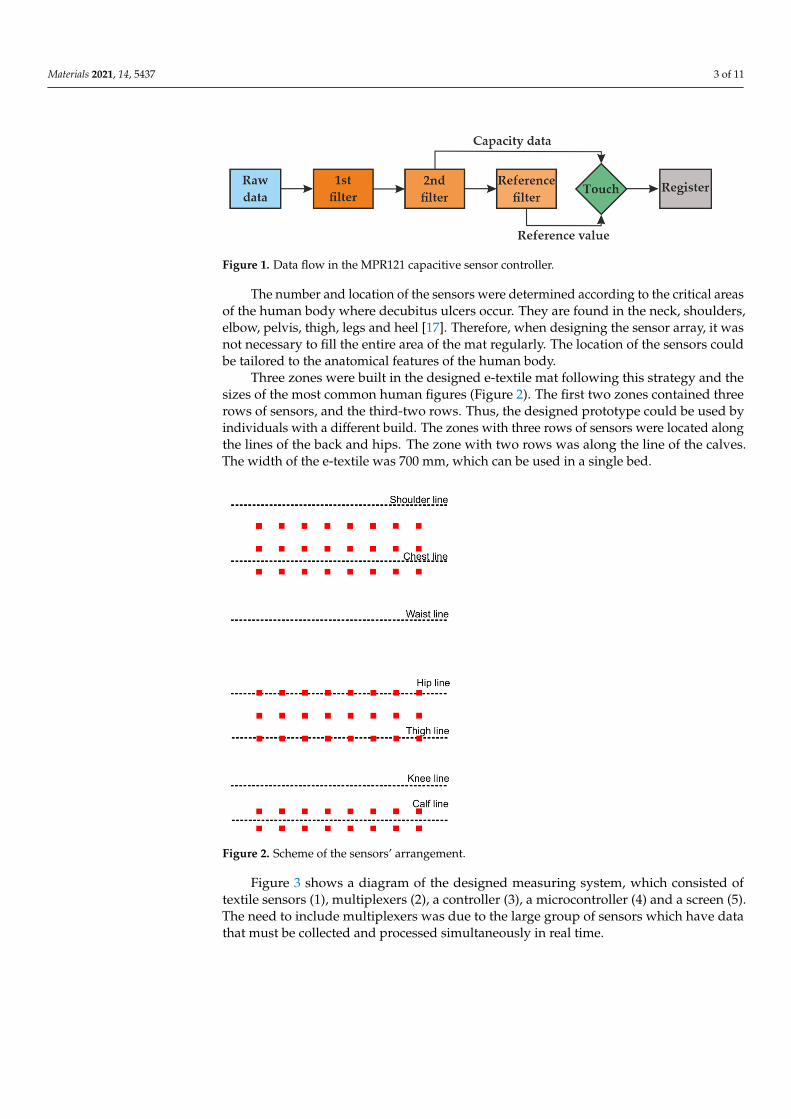
Figure 3 shows a diagram of the designed measuring system, which consisted oftextile sensors (1), multiplexers (2), a controller (3), a microcontroller (4) and a screen (5).The need to include multiplexers was due to the large group of sensors which have datathat must be collected and processed simultaneously in real time.
Materials 2021, 14, 5437 4 of 11Materials 2021, 14, x FOR PEER REVIEW 4 of 11
Figure 3. Scheme of the measuring system: 1—sensors, 2—multiplexers, 3—controller, 4—micro‐
controller, and 5—screen.
The multiplexer has several inputs and one output. It acts as a circuit breaker, where
the connection is not mechanical, but is made through an integrated semiconductor cir‐
cuit.
The entire development kit consists of a 12 bit ADC, Raspberry Pi 4 and 5” display.
The first module was the Pi HAT version of the Adafruit MPR121 capacitive sensor. It
measured 65 × 56 mm2 and had 12 sensor channels. It can be mounted on a Raspberry Pi
4.
The Raspberry Pi 4 minicomputer with dimensions of 85 × 56 mm2 works with an
ARM processor. It has 2 GB of memory and multiple interfaces: 2 × micro‐HDMI, TV/Au‐
dio OUT, 300 mbps ethernet, dual‐band Wi‐Fi, Bluetooth 5, micro‐SD, 2 × USB 3.0, 2 × USB
2.0, over 20 GPIO ports, I2C, SPI, UART, I2S, CSI, DSI, and USB 3.0 ports and is powered
by 5 V.
Connecting a display to the minicomputer makes it easier for the user to monitor the
results of the measuring system. It is compatible with Raspberry Pi 4.
2.3. The Textile Phase
The textile system, which plays the role of a carrier phase, can be developed from
layers of different types and thicknesses, which can vary in number. The most important
properties for the upper layer of the system are high wear resistance, low elongation un‐
der tensile load, good air permeability, lack of peeling and the possibility of trouble‐free
machine embroidery. The woven macrostructures had better performance than the knit‐
ted macrostructures in terms of low elongation under tensile load. Therefore, a woven
fabric of 100% cotton with mass per unit area of 230 g/m2 was chosen for the e‐textile mat.
The requirements for the second layer were good air permeability, good absorption
and low cost.
2.4. Embedding of the Sensors
2.4.1. Machine Embroidering
From the analysis of the motifs applied so far for developing resistive and capacitive
textile sensors by machine embroidery [6–8,12,13], it was found that the motif’s shape was
usually rectangular, filled with weave stitch line. The weave stitch line (Figure 4) is used
in objects where covering stitches are needed or in combination with other types of un‐
derlay stitches. Only the authors of a recent publication [13] studied five motifs in which
Figure 3. Scheme of the measuring system: 1—sensors, 2—multiplexers, 3—controller, 4—microcontroller, and 5—screen.
The multiplexer has several inputs and one output. It acts as a circuit breaker, wherethe connection is not mechanical, but is made through an integrated semiconductor circuit.
The entire development kit consists of a 12 bit ADC, Raspberry Pi 4 and 5” display. Thefirst module was the Pi HAT version of the Adafruit MPR121 capacitive sensor. It measured65 × 56 mm2 and had 12 sensor channels. It can be mounted on a Raspberry Pi 4.
The Raspberry Pi 4 minicomputer with dimensions of 85 × 56 mm2 works withan ARM processor. It has 2 GB of memory and multiple interfaces: 2 × micro-HDMI,TV/Audio OUT, 300 mbps ethernet, dual-band Wi-Fi, Bluetooth 5, micro-SD, 2 × USB 3.0,2 × USB 2.0, over 20 GPIO ports, I2C, SPI, UART, I2S, CSI, DSI, and USB 3.0 ports and ispowered by 5 V.
Connecting a display to the minicomputer makes it easier for the user to monitor theresults of the measuring system. It is compatible with Raspberry Pi 4.
2.3. The Textile Phase
The textile system, which plays the role of a carrier phase, can be developed fromlayers of different types and thicknesses, which can vary in number. The most importantproperties for the upper layer of the system are high wear resistance, low elongationunder tensile load, good air permeability, lack of peeling and the possibility of trouble-freemachine embroidery. The woven macrostructures had better performance than the knittedmacrostructures in terms of low elongation under tensile load. Therefore, a woven fabricof 100% cotton with mass per unit area of 230 g/m2 was chosen for the e-textile mat.
The requirements for the second layer were good air permeability, good absorptionand low cost.
2.4. Embedding of the Sensors2.4.1. Machine Embroidering
From the analysis of the motifs applied so far for developing resistive and capacitivetextile sensors by machine embroidery [6–8,12,13], it was found that the motif’s shape wasusually rectangular, filled with weave stitch line. The weave stitch line (Figure 4) is used inobjects where covering stitches are needed or in combination with other types of underlaystitches. Only the authors of a recent publication [13] studied five motifs in which thedistance between the electrodes was constantly preserved and the length of the conductivethread was significantly reduced.

Materials 2021, 14, 5437 5 of 11
Materials 2021, 14, x FOR PEER REVIEW 5 of 11
the distance between the electrodes was constantly preserved and the length of the con‐
ductive thread was significantly reduced.
Figure 4. Object with a weave stitch line.
The machine embroidery of the sensors was made with an MB4 Janome machine with
one head and four needles. Madeira Germany conductive HC 12 thread was used for the
upper and lower threads. HC 12 is a twisted polyester polyfilament with silver coating, a
linear density of 235 × 2 dtex and an electrical resistance < 100 Ω/m. The main disad‐
vantage of this thread is its durability, which according to [18], is approximately 10 wash‐
ing cycles. The best performance had the stainless‐steel microfibre thread, but there were
difficulties with its application in machine embroidery.
A crucial feature of the embroidery of electrically conductive threads is that the work
process is not interrupted due to the fact of thread break; otherwise, the electrical circuit
also breaks. It is also essential to avoid the accumulation of stitches on top of each other.
The test samples with the embroidered sensors were made with a woven macrostruc‐
ture in a twill weave (120 g/m2 mass per unit area) using a non‐woven macrostructure on
the backside (70 g/m2 mass per unit area).
2.4.2. Electrical Resistance and Capacitance Measuring
The measurement of the electrical resistance and capacitance was conducted with a
digital LCR‐819 m of GW Instek with an accuracy of 0.05%, capacity range from 0.00001
pF to 99.999 nF, electrical resistance ranging from 0.00001 to 99.999 Ω, and measurement
speed of 68 ms. The resistance was determined in five zones (1 to 5) of the embroidered
element according to the scheme in Figure 5.
Figure 5. Scheme for the electrical resistance measurement of the embroidered element: starting in
zone 1 and finishing in zone 5.
The experimental scheme for the capacitance measurement is presented in Figure 6.
The first electrode was the embroidered sensor, and the second was a flat parallel end
measure made of stainless steel with dimensions 30 × 32 × 8 mm3. A standard test was
performed at a voltage of 1 V and a frequency of 1 kHz.
Figure 4. Object with a weave stitch line.
The machine embroidery of the sensors was made with an MB4 Janome machinewith one head and four needles. Madeira Germany conductive HC 12 thread was usedfor the upper and lower threads. HC 12 is a twisted polyester polyfilament with silvercoating, a linear density of 235 × 2 dtex and an electrical resistance < 100 Ω/m. The maindisadvantage of this thread is its durability, which according to [18], is approximately 10washing cycles. The best performance had the stainless-steel microfibre thread, but therewere difficulties with its application in machine embroidery.
A crucial feature of the embroidery of electrically conductive threads is that the workprocess is not interrupted due to the fact of thread break; otherwise, the electrical circuitalso breaks. It is also essential to avoid the accumulation of stitches on top of each other.
The test samples with the embroidered sensors were made with a woven macrostruc-ture in a twill weave (120 g/m2 mass per unit area) using a non-woven macrostructure onthe backside (70 g/m2 mass per unit area).
2.4.2. Electrical Resistance and Capacitance Measuring
The measurement of the electrical resistance and capacitance was conducted with adigital LCR-819 m of GW Instek with an accuracy of 0.05%, capacity range from 0.00001pF to 99.999 nF, electrical resistance ranging from 0.00001 to 99.999 Ω, and measurementspeed of 68 ms. The resistance was determined in five zones (1 to 5) of the embroideredelement according to the scheme in Figure 5.
Materials 2021, 14, x FOR PEER REVIEW 5 of 11
the distance between the electrodes was constantly preserved and the length of the con‐
ductive thread was significantly reduced.
Figure 4. Object with a weave stitch line.
The machine embroidery of the sensors was made with an MB4 Janome machine with
one head and four needles. Madeira Germany conductive HC 12 thread was used for the
upper and lower threads. HC 12 is a twisted polyester polyfilament with silver coating, a
linear density of 235 × 2 dtex and an electrical resistance < 100 Ω/m. The main disad‐
vantage of this thread is its durability, which according to [18], is approximately 10 wash‐
ing cycles. The best performance had the stainless‐steel microfibre thread, but there were
difficulties with its application in machine embroidery.
A crucial feature of the embroidery of electrically conductive threads is that the work
process is not interrupted due to the fact of thread break; otherwise, the electrical circuit
also breaks. It is also essential to avoid the accumulation of stitches on top of each other.
The test samples with the embroidered sensors were made with a woven macrostruc‐
ture in a twill weave (120 g/m2 mass per unit area) using a non‐woven macrostructure on
the backside (70 g/m2 mass per unit area).
2.4.2. Electrical Resistance and Capacitance Measuring
The measurement of the electrical resistance and capacitance was conducted with a
digital LCR‐819 m of GW Instek with an accuracy of 0.05%, capacity range from 0.00001
pF to 99.999 nF, electrical resistance ranging from 0.00001 to 99.999 Ω, and measurement
speed of 68 ms. The resistance was determined in five zones (1 to 5) of the embroidered
element according to the scheme in Figure 5.
Figure 5. Scheme for the electrical resistance measurement of the embroidered element: starting in
zone 1 and finishing in zone 5.
The experimental scheme for the capacitance measurement is presented in Figure 6.
The first electrode was the embroidered sensor, and the second was a flat parallel end
measure made of stainless steel with dimensions 30 × 32 × 8 mm3. A standard test was
performed at a voltage of 1 V and a frequency of 1 kHz.
Figure 5. Scheme for the electrical resistance measurement of the embroidered element: starting inzone 1 and finishing in zone 5.
The experimental scheme for the capacitance measurement is presented in Figure 6.The first electrode was the embroidered sensor, and the second was a flat parallel endmeasure made of stainless steel with dimensions 30 × 32 × 8 mm3. A standard test wasperformed at a voltage of 1 V and a frequency of 1 kHz.

Materials 2021, 14, 5437 6 of 11Materials 2021, 14, x FOR PEER REVIEW 6 of 11
Figure 6. Scheme for the capacitance measurement.
3. Results and Discussion
3.1. Selection of the Textile Sensors
When incorporating the sensors using embroidery with conductive threads, it is cru‐
cial to follow specific rules:
Avoid overlapping stitches;
Minimum thread length;
Making the motif without breaking/cutting the threads.
Five motifs were developed to incorporate the sensors in the textile systems: concen‐
tric circles, cobweb, spiral, five‐pointed star and Hilbert curve. They were designed based
on known mathematical functions and fractals and observed work conditions with con‐
ductive threads. These variants have not been proposed in the literature yet. The sensor
designs were made with 3D modelling software, after which the embroideries were cre‐
ated with Digitizer MB V 3.0 (Figure 7).
Figure 7. Design of the sensor patterns: (a) concentric circles; (b) cobweb; (c) five‐pointed star; (d)
spiral; (e) Hilbert curve.
All motifs were designed with the same overall size of 20 mm, which is in full ac‐
cordance with the literature. Straight double‐sided stitch line, which consumes less thread
Figure 6. Scheme for the capacitance measurement.
3. Results and Discussion3.1. Selection of the Textile Sensors
When incorporating the sensors using embroidery with conductive threads, it iscrucial to follow specific rules:
• Avoid overlapping stitches;• Minimum thread length;• Making the motif without breaking/cutting the threads.
Five motifs were developed to incorporate the sensors in the textile systems: concentriccircles, cobweb, spiral, five-pointed star and Hilbert curve. They were designed based onknown mathematical functions and fractals and observed work conditions with conductivethreads. These variants have not been proposed in the literature yet. The sensor designswere made with 3D modelling software, after which the embroideries were created withDigitizer MB V 3.0 (Figure 7).
Materials 2021, 14, x FOR PEER REVIEW 6 of 11
Figure 6. Scheme for the capacitance measurement.
3. Results and Discussion
3.1. Selection of the Textile Sensors
When incorporating the sensors using embroidery with conductive threads, it is cru‐
cial to follow specific rules:
Avoid overlapping stitches;
Minimum thread length;
Making the motif without breaking/cutting the threads.
Five motifs were developed to incorporate the sensors in the textile systems: concen‐
tric circles, cobweb, spiral, five‐pointed star and Hilbert curve. They were designed based
on known mathematical functions and fractals and observed work conditions with con‐
ductive threads. These variants have not been proposed in the literature yet. The sensor
designs were made with 3D modelling software, after which the embroideries were cre‐
ated with Digitizer MB V 3.0 (Figure 7).
Figure 7. Design of the sensor patterns: (a) concentric circles; (b) cobweb; (c) five‐pointed star; (d)
spiral; (e) Hilbert curve.
All motifs were designed with the same overall size of 20 mm, which is in full ac‐
cordance with the literature. Straight double‐sided stitch line, which consumes less thread
Figure 7. Design of the sensor patterns: (a) concentric circles; (b) cobweb; (c) five-pointed star; (d)spiral; (e) Hilbert curve.
All motifs were designed with the same overall size of 20 mm, which is in fullaccordance with the literature. Straight double-sided stitch line, which consumes less
Materials 2021, 14, 5437 7 of 11
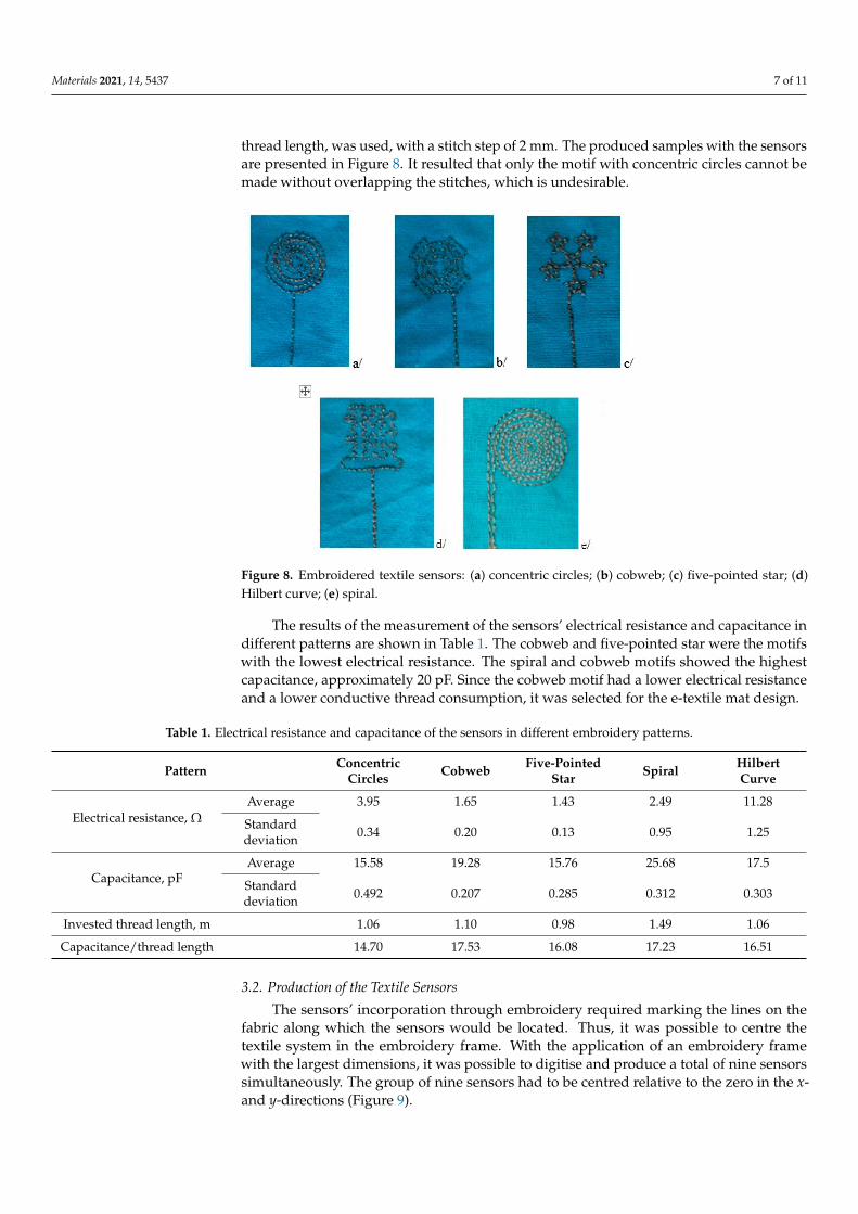
thread length, was used, with a stitch step of 2 mm. The produced samples with the sensorsare presented in Figure 8. It resulted that only the motif with concentric circles cannot bemade without overlapping the stitches, which is undesirable.
Figure 8. Embroidered textile sensors: (a) concentric circles; (b) cobweb; (c) five-pointed star; (d)Hilbert curve; (e) spiral.
The results of the measurement of the sensors’ electrical resistance and capacitance indifferent patterns are shown in Table 1. The cobweb and five-pointed star were the motifswith the lowest electrical resistance. The spiral and cobweb motifs showed the highestcapacitance, approximately 20 pF. Since the cobweb motif had a lower electrical resistanceand a lower conductive thread consumption, it was selected for the e-textile mat design.
Table 1. Electrical resistance and capacitance of the sensors in different embroidery patterns.
Pattern ConcentricCircles Cobweb Five-Pointed
Star Spiral HilbertCurve
Electrical resistance, ΩAverage 3.95 1.65 1.43 2.49 11.28
Standarddeviation 0.34 0.20 0.13 0.95 1.25
Capacitance, pFAverage 15.58 19.28 15.76 25.68 17.5
Standarddeviation 0.492 0.207 0.285 0.312 0.303
Invested thread length, m 1.06 1.10 0.98 1.49 1.06
Capacitance/thread length 14.70 17.53 16.08 17.23 16.51
3.2. Production of the Textile Sensors
The sensors’ incorporation through embroidery required marking the lines on thefabric along which the sensors would be located. Thus, it was possible to centre thetextile system in the embroidery frame. With the application of an embroidery framewith the largest dimensions, it was possible to digitise and produce a total of nine sensorssimultaneously. The group of nine sensors had to be centred relative to the zero in the x-and y-directions (Figure 9).

Materials 2021, 14, 5437 8 of 11
Materials 2021, 14, x FOR PEER REVIEW 8 of 11
largest dimensions, it was possible to digitise and produce a total of nine sensors simulta‐
neously. The group of nine sensors had to be centred relative to the zero in the x‐ and y‐
directions (Figure 9).
Figure 10 presents the embroidered textile sensors for body position. Because the
photo was taken at an angle, the rows of embroidered image sensors seem to be located
at an angle, resulting in image distortion.
Figure 9. The development of a program for the sensors’ incorporation with Digitizer MB.
Figure 10. The e‐textile mat with the embroidered textile sensors.
When incorporating the sensors, a certain length of the upper thread (approximately
15–20 cm) was left free to be connected with the flat ribbon cable passing from the reverse
side of the mat. The ribbon cable passed through the entire width of the product, ensuring
that an equal length of conductive thread was used for each sensor. Figure 11 shows an
image of the connected sensors with the flat ribbon cable using a cable lug. The width of
the ribbon cable was consistent with the number of sensors in the three groups. The ap‐
plication of a second layer in the mat ensured the preservation of the comfort and stability
of the product (to avoid the mat’s wrinkle when the body turns) during operation. An
ethylene‐vinyl acetate (EVA) foam could also be used for a second mat layer.
Figure 9. The development of a program for the sensors’ incorporation with Digitizer MB.
Figure 10 presents the embroidered textile sensors for body position. Because thephoto was taken at an angle, the rows of embroidered image sensors seem to be located atan angle, resulting in image distortion.
Materials 2021, 14, x FOR PEER REVIEW 8 of 11
largest dimensions, it was possible to digitise and produce a total of nine sensors simulta‐
neously. The group of nine sensors had to be centred relative to the zero in the x‐ and y‐
directions (Figure 9).
Figure 10 presents the embroidered textile sensors for body position. Because the
photo was taken at an angle, the rows of embroidered image sensors seem to be located
at an angle, resulting in image distortion.
Figure 9. The development of a program for the sensors’ incorporation with Digitizer MB.
Figure 10. The e‐textile mat with the embroidered textile sensors.
When incorporating the sensors, a certain length of the upper thread (approximately
15–20 cm) was left free to be connected with the flat ribbon cable passing from the reverse
side of the mat. The ribbon cable passed through the entire width of the product, ensuring
that an equal length of conductive thread was used for each sensor. Figure 11 shows an
image of the connected sensors with the flat ribbon cable using a cable lug. The width of
the ribbon cable was consistent with the number of sensors in the three groups. The ap‐
plication of a second layer in the mat ensured the preservation of the comfort and stability
of the product (to avoid the mat’s wrinkle when the body turns) during operation. An
ethylene‐vinyl acetate (EVA) foam could also be used for a second mat layer.
Figure 10. The e-textile mat with the embroidered textile sensors.
When incorporating the sensors, a certain length of the upper thread (approximately15–20 cm) was left free to be connected with the flat ribbon cable passing from the reverseside of the mat. The ribbon cable passed through the entire width of the product, ensuringthat an equal length of conductive thread was used for each sensor. Figure 11 shows animage of the connected sensors with the flat ribbon cable using a cable lug. The widthof the ribbon cable was consistent with the number of sensors in the three groups. Theapplication of a second layer in the mat ensured the preservation of the comfort andstability of the product (to avoid the mat’s wrinkle when the body turns) during operation.An ethylene-vinyl acetate (EVA) foam could also be used for a second mat layer.

Materials 2021, 14, 5437 9 of 11Materials 2021, 14, x FOR PEER REVIEW 9 of 11
Figure 11. The reverse side of the e‐textile mat with the embroidered textile sensors.
3.3. The Software Connection
Part of the project was developing specific software (application) for control of the
multiplexers, collecting the data from the controller of the capacitive sensors and sending
them in a protocol on a serial port. The application was created in the processing environ‐
ment for visualisation of the results. A more straightforward interface was offered to sim‐
plify the data reading by the user. A mesh of squares (visualising the sensors) was used,
which changed from black for the passive sensors to light green for the active. The depth
of the green colour varied according to the change in the capacitance, which represented
the pressure that the person exerted on the sensors. Therefore, it shows that the air gap
between the body and the sensors decreased or the overlapping area increased. This way,
the user (caregiver, medical staff) could be informed about the bedridden person’s posi‐
tion, which had not been changed.
To verify the data obtained from the sensors, experimental studies were performed
with an individual in two postures, essential for the human body in a supine position:
posture one, on the back (Figure 12), and posture two, in a sideways pose.
Figure 12. The experimental setup for the measurement with the e‐textile mat.
The sensor readings were displayed on the screen of the Raspberry Pi 4 minicom‐
puter. The squares with the darkest colour corresponded to the passive sensors, and those
with lighter ones to the activated ones. The motives that were obtained in the two postures
of the human body are presented in Figure 13.
Figure 11. The reverse side of the e-textile mat with the embroidered textile sensors.
3.3. The Software Connection
Part of the project was developing specific software (application) for control of themultiplexers, collecting the data from the controller of the capacitive sensors and sendingthem in a protocol on a serial port. The application was created in the processing envi-ronment for visualisation of the results. A more straightforward interface was offered tosimplify the data reading by the user. A mesh of squares (visualising the sensors) was used,which changed from black for the passive sensors to light green for the active. The depthof the green colour varied according to the change in the capacitance, which representedthe pressure that the person exerted on the sensors. Therefore, it shows that the air gapbetween the body and the sensors decreased or the overlapping area increased. This way,the user (caregiver, medical staff) could be informed about the bedridden person’s position,which had not been changed.
To verify the data obtained from the sensors, experimental studies were performedwith an individual in two postures, essential for the human body in a supine position:posture one, on the back (Figure 12), and posture two, in a sideways pose.
Materials 2021, 14, x FOR PEER REVIEW 9 of 11
Figure 11. The reverse side of the e‐textile mat with the embroidered textile sensors.
3.3. The Software Connection
Part of the project was developing specific software (application) for control of the
multiplexers, collecting the data from the controller of the capacitive sensors and sending
them in a protocol on a serial port. The application was created in the processing environ‐
ment for visualisation of the results. A more straightforward interface was offered to sim‐
plify the data reading by the user. A mesh of squares (visualising the sensors) was used,
which changed from black for the passive sensors to light green for the active. The depth
of the green colour varied according to the change in the capacitance, which represented
the pressure that the person exerted on the sensors. Therefore, it shows that the air gap
between the body and the sensors decreased or the overlapping area increased. This way,
the user (caregiver, medical staff) could be informed about the bedridden person’s posi‐
tion, which had not been changed.
To verify the data obtained from the sensors, experimental studies were performed
with an individual in two postures, essential for the human body in a supine position:
posture one, on the back (Figure 12), and posture two, in a sideways pose.
Figure 12. The experimental setup for the measurement with the e‐textile mat.
The sensor readings were displayed on the screen of the Raspberry Pi 4 minicom‐
puter. The squares with the darkest colour corresponded to the passive sensors, and those
with lighter ones to the activated ones. The motives that were obtained in the two postures
of the human body are presented in Figure 13.
Figure 12. The experimental setup for the measurement with the e-textile mat.
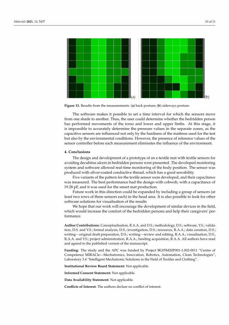
The sensor readings were displayed on the screen of the Raspberry Pi 4 minicomputer.The squares with the darkest colour corresponded to the passive sensors, and those withlighter ones to the activated ones. The motives that were obtained in the two postures ofthe human body are presented in Figure 13.
Materials 2021, 14, 5437 10 of 11Materials 2021, 14, x FOR PEER REVIEW 10 of 11
Figure 13. Results from the measurements: (a) back posture; (b) sideways posture.
The software makes it possible to set a time interval for which the sensors move from
one shade to another. Thus, the user could determine whether the bedridden person has
performed movements of the torso and lower and upper limbs. At this stage, it is impos‐
sible to accurately determine the pressure values in the separate zones, as the capacitive
sensors are influenced not only by the hardness of the mattress used for the test but also
by the environmental conditions. However, the presence of reference values of the sensor
controller before each measurement eliminates the influence of the environment.
4. Conclusions
The design and development of a prototype of an e‐textile mat with textile sensors
for avoiding decubitus ulcers in bedridden persons were presented. The developed mon‐
itoring system and software allowed real‐time monitoring of the body position. The sen‐
sor was produced with silver‐coated conductive thread, which has a good sewability.
Five variants of the pattern for the textile sensor were developed, and their capaci‐
tance was measured. The best performance had the design with cobweb, with a capaci‐
tance of 19.28 pF, and it was used for the smart mat production.
Future work in this direction could be expanded by including a group of sensors (at
least two rows of three sensors each) in the head area. It is also possible to look for other
software solutions for visualisation of the results
We hope that our work will encourage the development of similar devices in the
field, which would increase the comfort of the bedridden persons and help their caregiv‐
ers’ performance.
Author Contributions: Conceptualisation, R.A.A. and D.S.; methodology, D.S.; software, Y.S.; vali‐
dation, D.S. and Y.S.; formal analysis, D.S.; investigation, D.S.; resources, R.A.A.; data curation, D.S.;
writing—original draft preparation, D.S.; writing—review and editing, R.A.A.; visualisation, D.S.,
R.A.A. and Y.S.; project administration, R.A.A.; funding acquisition, R.A.A. All authors have read
and agreed to the published version of the manuscript.
Funding: The study and the APC was funded by Project BG05M20P001-1.002-0011 “Centre of Com‐petence MIRACle—Mechatronics, Innovation, Robotics, Automation, Clean Technologies”, Labor‐
atory 3.4 “Intelligent Mechatronic Solutions in the Field of Textiles and Clothing”.
Institutional Review Board Statement: Not applicable.
Informed Consent Statement: Not applicable.
Data Availability Statement: Not applicable.
Conflicts of Interest: The authors declare no conflict of interest.
Figure 13. Results from the measurements: (a) back posture; (b) sideways posture.
The software makes it possible to set a time interval for which the sensors movefrom one shade to another. Thus, the user could determine whether the bedridden personhas performed movements of the torso and lower and upper limbs. At this stage, itis impossible to accurately determine the pressure values in the separate zones, as thecapacitive sensors are influenced not only by the hardness of the mattress used for the testbut also by the environmental conditions. However, the presence of reference values of thesensor controller before each measurement eliminates the influence of the environment.
4. Conclusions
The design and development of a prototype of an e-textile mat with textile sensors foravoiding decubitus ulcers in bedridden persons were presented. The developed monitoringsystem and software allowed real-time monitoring of the body position. The sensor wasproduced with silver-coated conductive thread, which has a good sewability.
Five variants of the pattern for the textile sensor were developed, and their capacitancewas measured. The best performance had the design with cobweb, with a capacitance of19.28 pF, and it was used for the smart mat production.
Future work in this direction could be expanded by including a group of sensors (atleast two rows of three sensors each) in the head area. It is also possible to look for othersoftware solutions for visualisation of the results
We hope that our work will encourage the development of similar devices in the field,which would increase the comfort of the bedridden persons and help their caregivers’ per-formance.
Author Contributions: Conceptualisation, R.A.A. and D.S.; methodology, D.S.; software, Y.S.; valida-tion, D.S. and Y.S.; formal analysis, D.S.; investigation, D.S.; resources, R.A.A.; data curation, D.S.;writing—original draft preparation, D.S.; writing—review and editing, R.A.A.; visualisation, D.S.,R.A.A. and Y.S.; project administration, R.A.A.; funding acquisition, R.A.A. All authors have readand agreed to the published version of the manuscript.
Funding: The study and the APC was funded by Project BG05M20P001-1.002-0011 “Centre ofCompetence MIRACle—Mechatronics, Innovation, Robotics, Automation, Clean Technologies”,Laboratory 3.4 “Intelligent Mechatronic Solutions in the Field of Textiles and Clothing”.
Institutional Review Board Statement: Not applicable.
Informed Consent Statement: Not applicable.
Data Availability Statement: Not applicable.
Conflicts of Interest: The authors declare no conflict of interest.

Materials 2021, 14, 5437 11 of 11
References1. Vgontzas, A.N.; Chrousos, G.P. Sleep, the hypothalamic–pituitary–adrenal axis, and cytokines: Multiple interactions and
disturbances in sleep disorders. Endocrinol. Metab. Clin. 2002, 31, 15–36. [CrossRef]2. Bansal, C.; Scott, R.; Stewart, D.; Cockerell, C.J. Decubitus ulcers: A review of the literature. Int. J. Dermatol. 2005, 44, 805–810.
[CrossRef] [PubMed]3. Buckle, P.; Fernandes, A. Mattress evaluation—Assessment of contact pressure, comfort and discomfort. Appl. Ergon. 1998, 29,
35–39. [CrossRef]4. Chen, Y.X.; Shen, L.M.; Guo, Y.; Shao, T.T.; Fang, F.; Sun, Y.; Zhong, S.; Lu, T. Relationship between mattress comfort and sleep
quality. J. Anhui Agric. Univ. 2012, 3, 115–120.5. Orcioni, S.; Conti, M.; Martínez Madrid, N.; Gaiduk, M.; Seepold, R. A review of health monitoring systems using sensors on bed
or cushion. In Proceedings of the International Workshop “Smart-Future-Living-Bodensee”, Konstanz, Germany, 24 November2017; HTWG: Konstanz, Germany, 2018; pp. 45–48.
6. Parzer, P.; Perteneder, F.; Probst, K.; Rendl, C.; Leong, J.; Schuetz, S.; Vogl, A.; Schwoediauer, R.; Kaltenbrunner, M.; Bauer, S.; et al.RESi: A Highly Flexible, Pressure-Sensitive, Imperceptible Textile Interface Based on Resistive Yarns. In Proceedings of the 31stAnnual ACM Symposium on User Interface Software and Technology, Berlin Germany, 14–17 October 2018; pp. 745–756.
7. Sergio, M.; Manaresi, N.; Tartagni, M.; Guerrieri, R.; Canegallo, R. A textile based capacitive pressure sensor. In Proceedings ofthe SENSORS, 2002 IEEE, Orlando, FL, USA, 12–14 June 2002; Volume 2, pp. 1625–1630.
8. Meyer, J.; Arnrich, B.; Schumm, J.; Troster, G. Design and modeling of a textile pressure sensor for sitting posture classification.IEEE Sens. J. 2010, 10, 1391–1398. [CrossRef]
9. Post, E.R.; Orth, M.; Russo, P.R.; Gershenfeld, N. E-broidery: Design and fabrication of textile-based computing. IBM Syst. J. 2000,39, 840–860. [CrossRef]
10. Poupyrev, I.; Gong, N.W.; Fukuhara, S.; Karagozler, M.E.; Schwesig, C.; Robinson, K.E. Project Jacquard: Interactive digital textilesat scale. In Proceedings of the 2016 CHI Conference on Human Factors in Computing Systems, San Jose, CA, USA, 7–12 May2016; pp. 4216–4227.
11. Rofouei, M.; Xu, W.; Sarrafzadeh, M. Computing with uncertainty in a smart textile surface for object recognition. In Proceedingsof the 2010 IEEE Conference on Multisensor Fusion and Integration, Salt Lake City, UT, USA, 5–7 September 2010; pp. 174–179.
12. Xu, W.; Huang, M.C.; Amini, N.; He, L.; Sarrafzadeh, M. eCushion: A textile pressure sensor array design and calibration forsitting posture analysis. IEEE Sens. J. 2013, 13, 3926–3934. [CrossRef]
13. Aigner, R.; Pointner, A.; Preindl, T.; Parzer, P.; Haller, M. Embroidered resistive pressure sensors: A novel approach for textileinterfaces. In Proceedings of the 2020 CHI Conference on Human Factors in Computing Systems, Honolulu, HI, USA, 25–30April 2020; pp. 1–13.
14. Sofronova, D. Application and technologies for textile sensors production used in pressure distribution measurement-a criticalreview. E3S Web Conf. 2020, 207, 03001. [CrossRef]
15. Orth, M. Defining flexibility and sewability in conductive yarns. MRS Online Proc. Libr. (OPL) 2002, 736, D1.4. [CrossRef]16. Sofronova, D.; Angelova, R.A. Embedding Sensors by E-embroidery: Practical Steps for Smart Textiles Production. In Proceedings
of the 2021 6th International Symposium on Environment-Friendly Energies and Applications (EFEA), Sofia, Bulgaria, 24–26March 2021; pp. 1–5.
17. Angelova, R.A.; Sofronova, D. E-textile for non-invasive control of the body movement of bedridden patients. IOP Conf. Ser.Mater. Sci. Eng. 2021, 1031, 012029. [CrossRef]
18. Briedis, U.; Valisevskis, A.; Ziemele, I.; Abele, I. Study of Durability of Conductive Threads Used for Integration of Electronicsinto Smart Clothing. Key Eng. Mater. 2019, 800, 320–325. [CrossRef]


![[XLS] for the month Apr... · Web viewMargin MarketType MarketType MarketType MarketType MarketType_Text MarketType_Text Mast Mast Mat Mat Mat Mat Mat Mat Mat Mat Mat Mat Mat Match1](https://img.pdfslide.us/doc/110x75/5ab4774c7f8b9a2f438b92c4/xls-for-the-month-aprweb-viewmargin-markettype-markettype-markettype-markettype.jpg)