Embed Size (px)
Citation preview
DESIGN AND DEVELOPMENT OF AN AGV USING RF
MODULE
A THESIS SUBMITTED IN PARTIAL FULFILLMENT
OF THE REQUIREMENTS FOR THE DEGREE OF
Bachelor of Technology
In
Mechanical Engineering
By
PRADEEP KUMAR PATI
Department of Mechanical Engineering
National Institute of Technology
Rourkela
2007
DESIGN AND DEVELOPMENT OF AN AGV USING RF
MODULE
A THESIS SUBMITTED IN PARTIAL FULFILLMENT
OF THE REQUIREMENTS FOR THE DEGREE OF
Bachelor of Technology
In
Mechanical Engineering
By
PRADEEP KUMAR PATI
Under the Guidance of
Prof. C. K. Biswas
Department of Mechanical Engineering
National Institute of Technology
Rourkela
2007

National Institute of Technology
Rourkela
CERTIFICATE
This is to certify that the thesis entitled, “Design and Development of an AGV using RF
Module” submitted by Sri Pradeep Kumar Pati in partial fulfillment of the requirements for the
award of Bachelor of Technology Degree in Mechanical Engineering at the National Institute of
Technology, Rourkela (Deemed University) is an authentic work carried out by him under my
supervision and guidance.
To the best of my knowledge, the matter embodied in the thesis has not been submitted to any
other University / Institute for the award of any Degree or Diploma.
Date Prof. C.K. Biswas
Dept. of Mechanical Engineering
National Institute of Technology
Rourkela - 769008
i

National Institute of Technology
Rourkela
ACKNOWLEDGEMENT
I would like to articulate my deep gratitude to my project guide Dr. C.K. Biswas who has always
been my motivation for carrying out the project.
I also extend my thanks to my seniors Mr. Ramana Reddy N. and Mr. Ware Shivkumar who
furthered this project to this extent and documented the whole process.
It is my pleasure to refer Microsoft word 2003 of which the compilation of this report would
have been impossible.
An assemblage of this nature could never have been attempted without reference to and
inspiration from the works of others whose details are mentioned in reference section. I
acknowledge my indebtedness to all of them.
Last but not the least to all of my friends who were patiently extended all sorts of help for
accomplishing this undertaking.
Date Pradeep Kumar Pati
Dept. of Mechanical Engineering
National Institute of Technology
Rourkela - 769008
ii
CONTENTS
Sl. No. Topic Page
1 Certificate i
2 Acknowledgement ii
3 Contents iii
4 Abstract iv
5 List of figures v
7 Chapter 1 : Introduction
History
Benefits
Cost
1
3
4
4
8 Chapter 2 : Design
Objectives
ATMEGA16 Microcontroller
Navigation
Drive/Steering
Power Supply
5
5
5
10
11
14
9 Chapter 3 : Communication Systems
Various Communication Systems
RF Communication
Digital RF Communication
Chosen RF Solution
15
15
17
19
22
10 Chapter 4 : USART on ATMEGA16
Introduction
Registers
23
23
24
11 Chapter 5 : Conclusion
Results and Discussion
Conclusion
Scope for further Enhancement
27
27
27
28
12 Appendix : A : Program for the main microcontroller
B : Program for the auxiliary microcontroller
C : Control program for the PC
30
39
41
13 Reference 45
National Institute of Technology
Rourkela
ABSTRACT
Automated guided vehicles play an important role in the flexible manufacturing system. The
project mainly deals with the design and development of an AGV and controlling it with
computer through RF signals.
This includes several steps�
• Design of microcontroller on robot. Here ATMEGA 16 (AVR series of microcontroller)
is used as it is enabled with all sorts of required features.
• Design of driving systems. Stepper motors are used.
• Design of communication systems. RF modules are to be used to communicate data
between computer and AGV.
Driving system�
Stepper motors are used to drive the AGV. They are controlled by ATMEGA 16 microcontroller
and a driver chip to amplify the current to the motor.
Communication�
The details of position and feedback should be sent to the central computer and instructions
received to proceed to do further tasks. The communication has to be wireless to make things
easier. Available RF modules are to be used which are serial in nature .But before that, the
parallel data has to be converted into the serial data.
iv
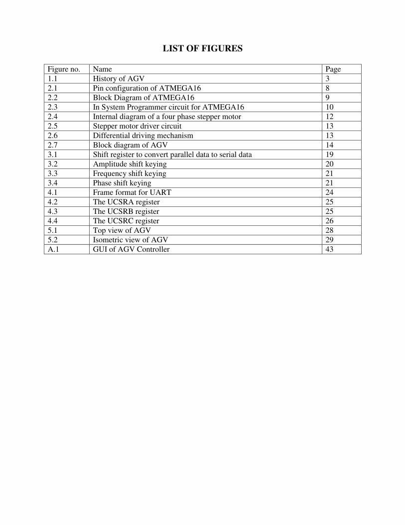
LIST OF FIGURES
Figure no. Name Page
1.1 History of AGV 3
2.1 Pin configuration of ATMEGA16 8
2.2 Block Diagram of ATMEGA16 9
2.3 In System Programmer circuit for ATMEGA16 10
2.4 Internal diagram of a four phase stepper motor 12
2.5 Stepper motor driver circuit 13
2.6 Differential driving mechanism 13
2.7 Block diagram of AGV 14
3.1 Shift register to convert parallel data to serial data 19
3.2 Amplitude shift keying 20
3.3 Frequency shift keying 21
3.4 Phase shift keying 21
4.1 Frame format for UART 24
4.2 The UCSRA register 25
4.3 The UCSRB register 25
4.4 The UCSRC register 26
5.1 Top view of AGV 28
5.2 Isometric view of AGV 29
A.1 GUI of AGV Controller 43

INTRODUCTION
History
Benefits
Cost
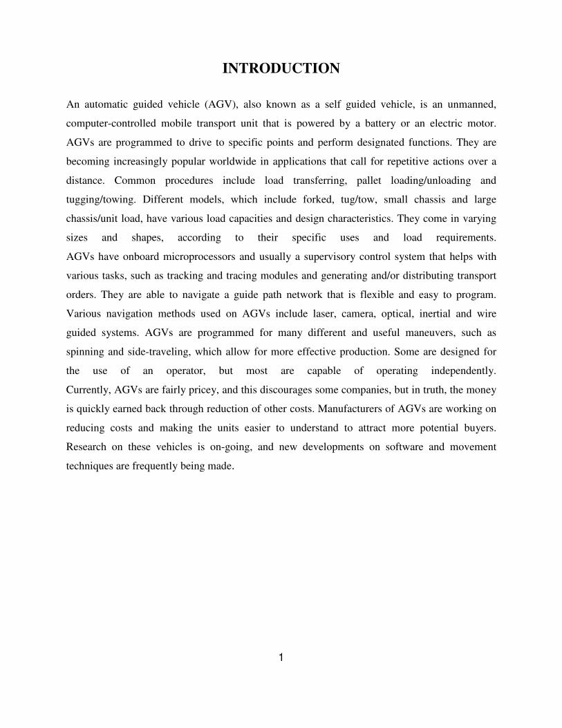
INTRODUCTION
An automatic guided vehicle (AGV), also known as a self guided vehicle, is an unmanned,
computer-controlled mobile transport unit that is powered by a battery or an electric motor.
AGVs are programmed to drive to specific points and perform designated functions. They are
becoming increasingly popular worldwide in applications that call for repetitive actions over a
distance. Common procedures include load transferring, pallet loading/unloading and
tugging/towing. Different models, which include forked, tug/tow, small chassis and large
chassis/unit load, have various load capacities and design characteristics. They come in varying
sizes and shapes, according to their specific uses and load requirements.
AGVs have onboard microprocessors and usually a supervisory control system that helps with
various tasks, such as tracking and tracing modules and generating and/or distributing transport
orders. They are able to navigate a guide path network that is flexible and easy to program.
Various navigation methods used on AGVs include laser, camera, optical, inertial and wire
guided systems. AGVs are programmed for many different and useful maneuvers, such as
spinning and side-traveling, which allow for more effective production. Some are designed for
the use of an operator, but most are capable of operating independently.
Currently, AGVs are fairly pricey, and this discourages some companies, but in truth, the money
is quickly earned back through reduction of other costs. Manufacturers of AGVs are working on
reducing costs and making the units easier to understand to attract more potential buyers.
Research on these vehicles is on-going, and new developments on software and movement
techniques are frequently being made.
1
Types of AGV�
Automated guided vehicle systems consist of the computer, software and technology that are the
“brains” behind the AGV. Without computer software systems and communications networks,
only the simplest AGV functions can be performed.
• Camera guided AGVs are used when precise guidance accuracy is needed, such as in
crowded environments and smaller sized facilities. An on-board camera focuses and
guides the AGV while performing.
• Forked AGVs are used to pick up and deliver various loads, such as pallets, carts, rolls
and others. These can be manually driven as well as used automatically, and have the
ability to lift loads to many levels.
• Inertial guided AGVs use a magnet sensing device, a gyroscope that measures the unit’s
heading and a wheel odometer that calculates the distance traveled. Magnets mounted
beneath the floor are detected by the on-board magnetic sensing device and combine with
the first two readings to give an accurate positional location.
• Large chassis/ unit load AGVs are used to transport heavier loads with various transfer
devices such as roller beds, lift/lower mechanisms and custom mechanisms.
• Laser guided AGVs use mounted laser scanners that emit a laser and reflect back from
targets. The vehicle’s location can be determined based on distance to the target and time
of reflection information.
• Optical guided AGVs use a latex-based photosensitive tape on a facility’s floor for
guidance. Distance is measured by use of wheel odometers, which establish stop
locations for the AGV along the course.
• Outrigger AGVs have two horizontal stabilizing legs (outriggers) to provide lateral
support, and are used to handle pallets, rolls and racks.
• Small chassis AGVs are able to maneuver through crowded workplaces through laser
sensing, while transporting smaller loads.
• Smart vehicle AGVs are capable of determining their own traffic control and routing
without necessitating a central controller.
2
• Tug/tow AGVs are used to pull trailers and are usually manned by an operator who adds
and removes the trailers at designated stops. These can follow a basic loop or a more
complicated path.
• Wire guided AGVs use a charged wire that is buried beneath the floor for proper
guidance and has small antennae composed of metal coils mounted on their bottoms. The
stronger the field between the buried wire and antennae, the higher the voltage induced to
the coils.
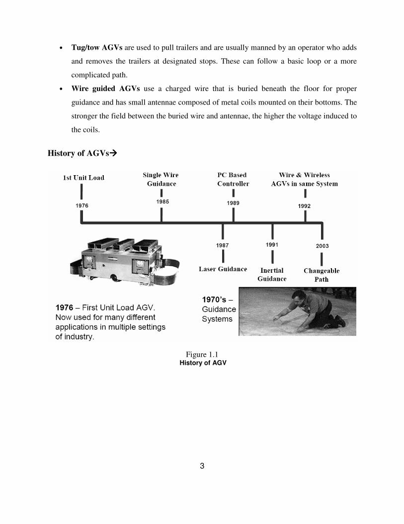
History of AGVs����
Figure 1.1 History of AGV
3
Benefits of AGVs����
Corporations that use AGVs, often factories, warehouses, hospitals and other large facilities,
benefit from the many advantages AGVs have to offer. One of the most beneficial is reduced
labor costs. AGVs do not tire like human workers, and when their batteries are drained, charging
the AGVs easily replenishes their energy. Loads that AGVs carry are far heavier than any single
human could manage, which makes transporting heavy objects quick and simple. AGVs help
give companies a competitive edge because they increase productivity and complete the job in an
effective and time-efficient manner. They are flexible and can be adapted to many different
needs. Also, using AGVs reduces damage to products and increases safety among workers. Some
typical advantages of any AGVs can be pin pointed to:
• Reduced labor and associated costs.
• Increased dependability and productivity.
• Fewer products handling damage.
Cost����
o Typically an AGV will cost about Rs.25lakh.
Maintenance costs are typically 3-5% of the overall system price.
4
DESIGN
Objectives
ATMEGA16 Microcontroller
Navigation
Drive/Steering
Power Supply
DESIGN Objectives����
The main design objectives of this work are:
� To control the mobile robot wirelessly with a computer
� Initially the robot is controlled with wire using parallel port and it is planned to replace
wire with Bluetooth device.
� To establish a system that allows many devices communicate simultaneously
� Since the number of AGVs is not limited to one, it is necessary to have a system which
allows more than one devices interact simultaneously with the server and the same is
provided by Bluetooth.
� To have a sensor arrangement that can identify each machine uniquely.
� Initially it is planned to place different number of sensors in each machine so that it can
be identified easily.
� To trace the right paint strip when there is a branch.
� When there is a branch, each strip is extended as shown in the figure so that it is easy for
sensor to identify the right one.
ATMEGA16 Microcontroller���� The inseparable part of the designed AGV are the ATMEGA 16. The microcontroller is the heart
of the AGV. It manipulates all the system and environment variables to take decision and hence
drives the vehicle accordingly.
Some of its notable features are�
• Consumes very less power
• Has an instruction set of 131 and most of them execute in a single clock cycle.
• Has a 16KB of programmable flash with In-System Programmability.
• Has an 8channel, 10 bit ADC, helpful for getting digital feedbacks.
5
ATMEGA16 Microcontroller Features:
• High-performance, Low-power AVR® 8-bit Microcontroller
• Advanced RISC Architecture
– 131 Powerful Instructions – Most Single-clock Cycle Execution
– 32 x 8 General Purpose Working Registers
– Fully Static Operation
– Up to 16 MIPS Throughput at 16 MHz
– On-chip 2-cycle Multiplier
• Nonvolatile Program and Data Memories
– 16K Bytes of In-System Self-Programmable Flash
Endurance: 10,000 Write/Erase Cycles
– Optional Boot Code Section with Independent Lock Bits
In-System Programming by On-chip Boot Program
True Read-While-Write Operation
– 512 Bytes EEPROM
Endurance: 100,000 Write/Erase Cycles
– 1K Byte Internal SRAM
– Programming Lock for Software Security
• JTAG (IEEE std. 1149.1 Compliant) Interface
– Boundary-scan Capabilities According to the JTAG Standard
– Extensive On-chip Debug Support
– Programming of Flash, EEPROM, Fuses, and Lock Bits through the JTAG Interface
• Peripheral Features
– Two 8-bit Timer/Counters with Separate Prescalers and Compare Modes
– One 16-bit Timer/Counter with Separate Prescaler, Compare Mode, and Capture
Mode
– Real Time Counter with Separate Oscillator
– Four PWM Channels
– 8-channel, 10-bit ADC
– Byte-oriented Two-wire Serial Interface
– Programmable Serial USART
6
– On-chip Analog Comparator
• I/O and Packages
– 32 Programmable I/O Lines
– 40-pin PDIP
• Speed Grades
– 0 - 16 MHz for ATmega16
• Power Consumption @ 1 MHz, 3V, and 25°C for ATmega16L
– Active: 1.1 mA
– Idle Mode: 0.35 mA
– Power-down Mode: < 1 µA
7
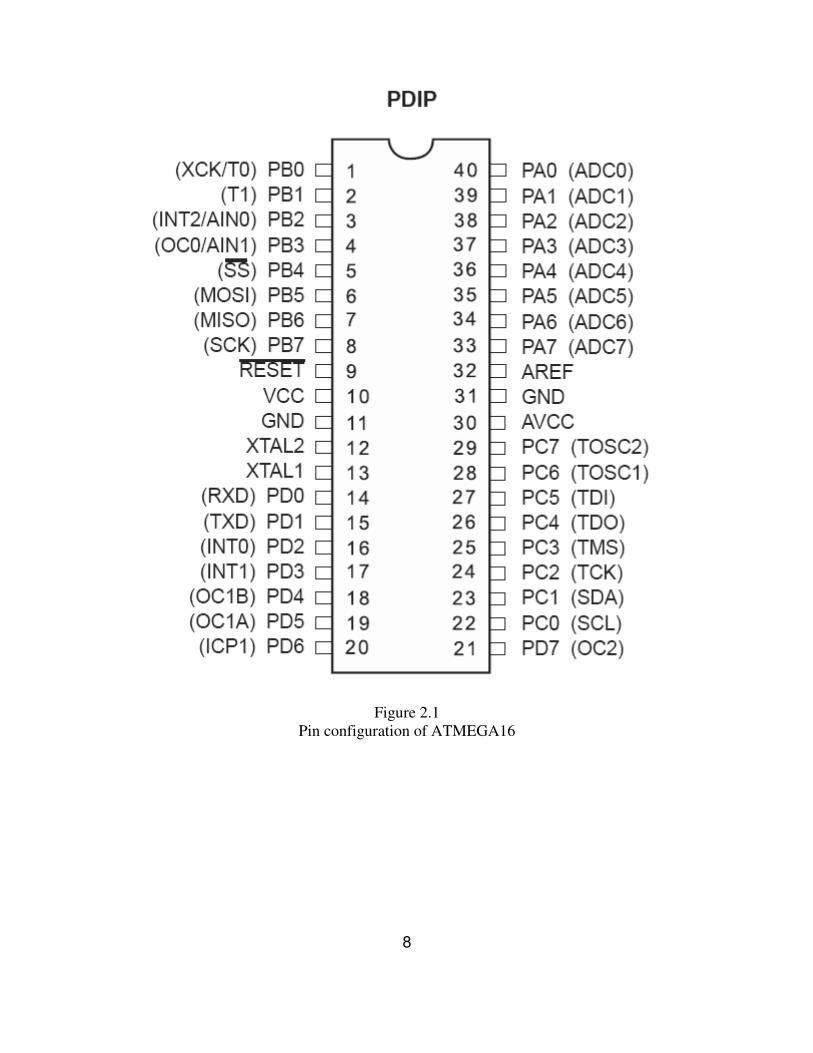
Figure 2.1
Pin configuration of ATMEGA16
8
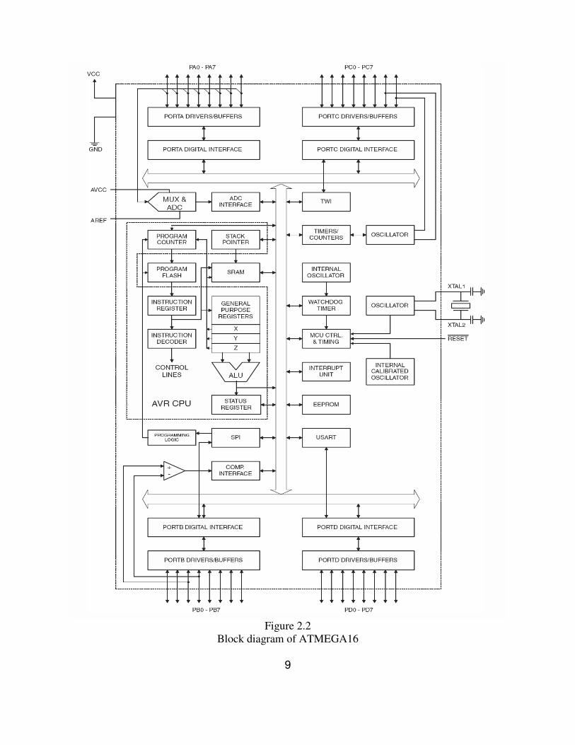
Figure 2.2
Block diagram of ATMEGA16
9
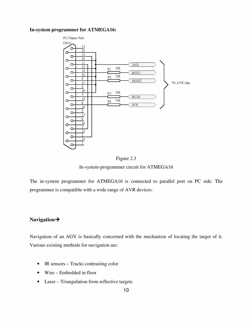
In-system programmer for ATMEGA16:
Figure 2.3
In-system-programmer circuit for ATMEGA16
The in-system programmer for ATMEGA16 is connected to parallel port on PC side. The
programmer is compatible with a wide range of AVR devices.
Navigation����
Navigation of an AGV is basically concerned with the mechanism of locating the target of it.
Various existing methods for navigation are:
• IR sensors – Tracks contrasting color
• Wire – Embedded in floor
• Laser – Triangulation from reflective targets
10
IR sensor arrangement:
In order for the robot to determine its position over the paint strip and identify any particular
machine, some kind of proximity sensing device is needed. After some consideration, an
infrared system was chosen for its simplicity. Other types of sensors (specifically ultrasonic) do
give higher degrees of accuracy when measuring distance; however, infrared remains a simple
and sufficient solution at a lower price tag. Additionally, the infrared sensing devices are
available locally. Simple IR LEDs and IR receivers are used. Here it is planned to use 4 sets of
IR sensors. They are mounted to the bottom of the vehicle in a single line perpendicular to the
paint strip. Usually, two sensors lie to one side of the strip and two to another side. If the vehicle
deviates from its path, any of the sensors detect the paint strip and the microcontroller controls
the motion accordingly.
Drive / Steering����
Stepper Motors and Stepper Driver Circuit:
In this project, 2 stepper motors each with a coil resistance of 5ohm and 1.2A current rating is
used.
When deciding how to move the robot, we realized that precision movement would be necessary
in order to avoid touching the undesirable components and machines. In order to achieve the
required precision in movement, it was decided that the robot would utilize stepper motors. The
main benefit of stepper motors is that they are able to turn a specific number of degrees for every
step. A four phase stepper motor has four coils that, when energized in a specific sequence,
rotate a driving magnetic field which, consequently, rotates a set of permanent magnets. These
permanent magnets are attached to a rotor which drives an output shaft. Thus, by pulsing the
coils in a certain sequence, a clockwise or counterclockwise movement can be attained.
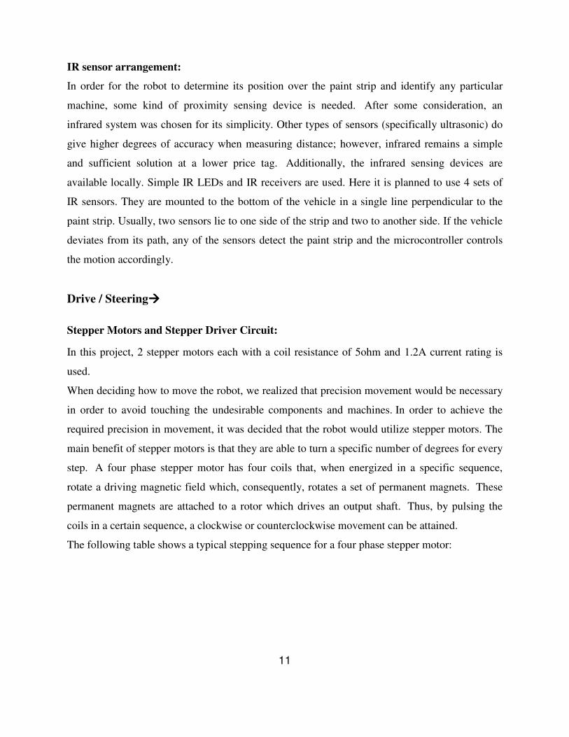
The following table shows a typical stepping sequence for a four phase stepper motor:
11
Step Sequence
1 2 3 4
Coil A on off off off
Coil A' off on off off
Coil B off off on off
Coil B' off off off on
Table2.1
Step Sequence in Stepper Motor
Figure 2.4
Internal Diagram of A Typical Four Phase Stepper Motor
The circuit shown in Figure is used to drive the motor coils. Because there are a total of eight
motor coils in the robot, eight of these circuits are needed. The circuit functions by receiving a
digital input from the microcontroller. This signal is fed to an opto-isolator in order to separate
12
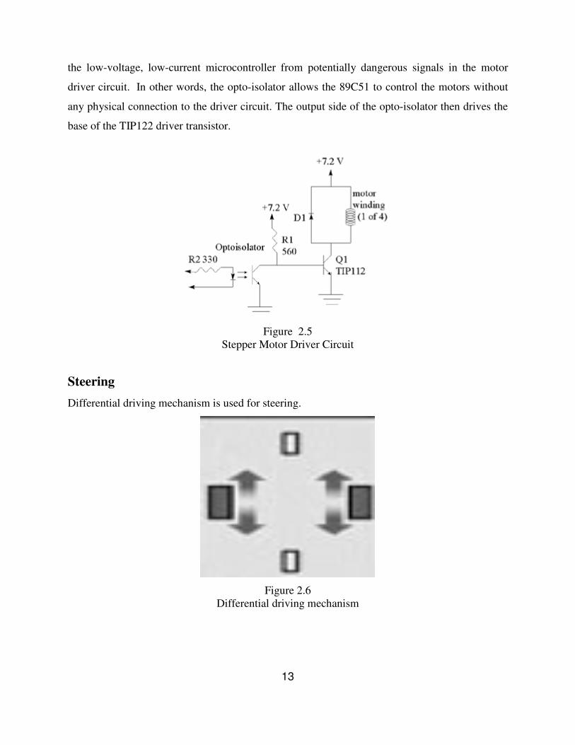
the low-voltage, low-current microcontroller from potentially dangerous signals in the motor
driver circuit. In other words, the opto-isolator allows the 89C51 to control the motors without
any physical connection to the driver circuit. The output side of the opto-isolator then drives the
base of the TIP122 driver transistor.
Figure 2.5
Stepper Motor Driver Circuit
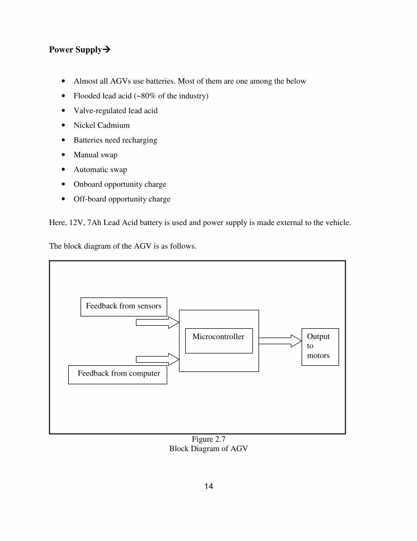
Steering
Differential driving mechanism is used for steering.
Figure 2.6
Differential driving mechanism
13
Power Supply����
• Almost all AGVs use batteries. Most of them are one among the below
• Flooded lead acid (~80% of the industry)
• Valve-regulated lead acid
• Nickel Cadmium
• Batteries need recharging
• Manual swap
• Automatic swap
• Onboard opportunity charge
• Off-board opportunity charge
Here, 12V, 7Ah Lead Acid battery is used and power supply is made external to the vehicle.
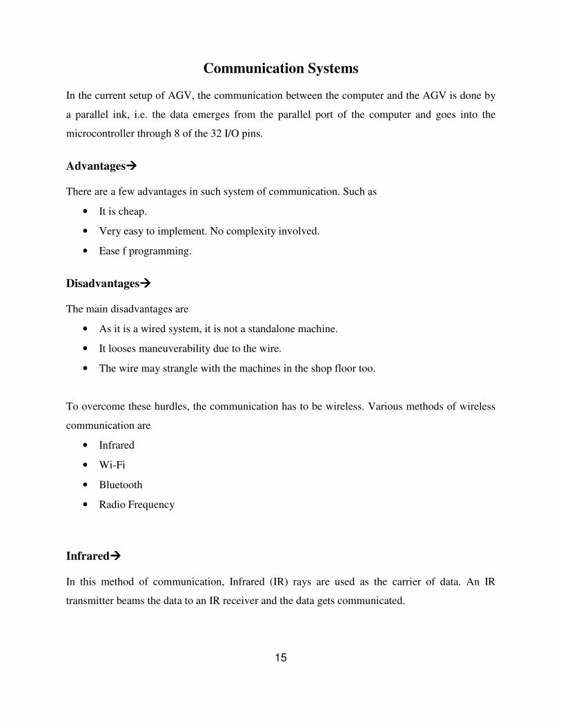
The block diagram of the AGV is as follows.
Figure 2.7
Block Diagram of AGV
14
Feedback from sensors
Feedback from computer
Output
to
motors
Microcontroller
COMMUNICATION SYSTEMS
Various Communication Systems
RF Communication
Digital RF communication
Chosen RF solution
Communication Systems In the current setup of AGV, the communication between the computer and the AGV is done by
a parallel ink, i.e. the data emerges from the parallel port of the computer and goes into the
microcontroller through 8 of the 32 I/O pins.
Advantages���� There are a few advantages in such system of communication. Such as
• It is cheap.
• Very easy to implement. No complexity involved.
• Ease f programming.
Disadvantages���� The main disadvantages are
• As it is a wired system, it is not a standalone machine.
• It looses maneuverability due to the wire.
• The wire may strangle with the machines in the shop floor too.
To overcome these hurdles, the communication has to be wireless. Various methods of wireless
communication are
• Infrared
• Wi-Fi
• Bluetooth
• Radio Frequency
Infrared���� In this method of communication, Infrared (IR) rays are used as the carrier of data. An IR
transmitter beams the data to an IR receiver and the data gets communicated.
15
Advantages����
The advantages are
• It is cheap.
• Easily implement able.
• Quite easy to find out the faults.
• Easy to operate.
Disadvantages����
The disadvantages are
• The transmitter and receiver have to be in line-of-sight in order to facilitate
communication.
• Very short range.
• Probable data loss.
As the AGV is not always in the line of sight with the controlling computer in a shop floor, we
detest ourselves from using this kind of wireless communication.
Wi-Fi����
This stands for Wireless Fidelity. Its aim is not to transfer data between 2 nodes, rather establish
a network between them. Wi-Fi is the standard defined by IEEE 802.11 and is widely used for
establishment of computer networks.
Advantages����
The advantages are
• Highly reliable
• Good compatibility, interoperability between vendors.
• High speed of data transfer
16
Disadvantages����
The drawbacks are
• Costly
• Requires high processing power
• Difficult to implement
• Operation requires high technical skills.
Bluetooth����
Bluetooth is a particular form of radio transmission system that operates at 2.4GHz and has a set
of rules defined by the IEEE. These set of rules include both connectivity and security ones.
Advantages����
The advantages are
• Quite cheap
• Easily available
Disadvantages����
The drawbacks include
• Difficult to implement
• Unduly high security
• Requires high technical skills for operation
• Very short range-10 meters
The short range of Bluetooth restricts it from being the ideal choice for communication.
RF Communication���� RF stands for Radio Frequency. It is defined as the frequency between 12 KHz to 30 MHz. This
is the basis of all other communications. Some of its main advantages follow.
17
Advantages����
• Easily available.
• Easily implement able.
• Low power consumption.
• High range with less power.
• Reliability.
Disadvantages����
1. Works with serial data only.
So RF is found out to be the ideal method for communication.
RF for Industrial use����
The most widely used industrial RF frequency is 433MHz as it is easy to produce and cheap
along with a range of about 1kM. This comes under Ultra High Frequency range. And this
frequency doesn’t interfere with other wireless products like Mobile phones, walkie-talkies etc.
By this frequency both analog and digital data can be transmitted, but as we are concerned with
digital data only, we will stick to that.
Yet another problem in RF communication is it uses serial data only, where as it is easy to work
with parallel data and our existing setup uses parallel data only. For this matter, we have to
convert the parallel data to serial data before transmission and again convert it back to parallel
data after receiving before feeding it to the microcontroller.
This can be done by a method known as Shift Register.
18
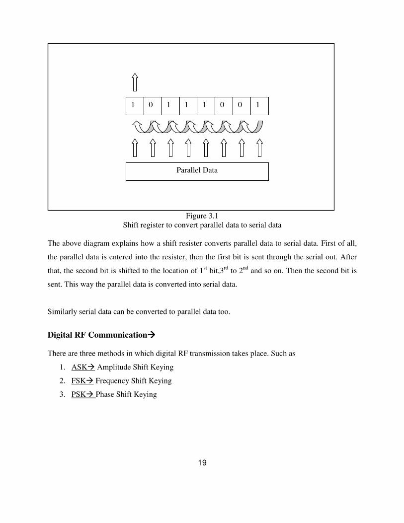
Figure 3.1
Shift register to convert parallel data to serial data
The above diagram explains how a shift resister converts parallel data to serial data. First of all,
the parallel data is entered into the resister, then the first bit is sent through the serial out. After
that, the second bit is shifted to the location of 1st bit,3
rd to 2
nd and so on. Then the second bit is
sent. This way the parallel data is converted into serial data.
Similarly serial data can be converted to parallel data too.
Digital RF Communication���� There are three methods in which digital RF transmission takes place. Such as
1. ASK� Amplitude Shift Keying
2. FSK� Frequency Shift Keying
3. PSK� Phase Shift Keying
19
1 1 0 1 1 0 0 1
Parallel Data
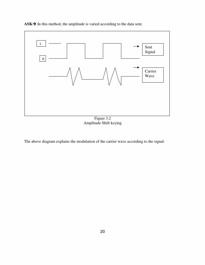
ASK���� In this method, the amplitude is varied according to the data sent.
Figure 3.2
Amplitude Shift keying
The above diagram explains the modulation of the carrier wave according to the signal.
20
1
0
Sent
Signal
Carrier
Wave
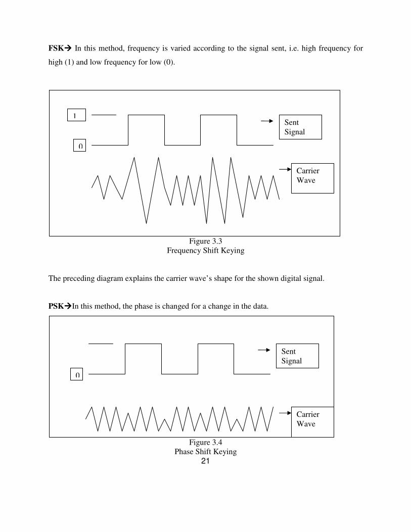
FSK���� In this method, frequency is varied according to the signal sent, i.e. high frequency for
high (1) and low frequency for low (0).
Figure 3.3
Frequency Shift Keying
The preceding diagram explains the carrier wave’s shape for the shown digital signal.
PSK����In this method, the phase is changed for a change in the data.
Figure 3.4
Phase Shift Keying
21
1
0
Sent
Signal
Carrier
Wave
0
Sent
Signal
Carrier
Wave
The above diagram shows how the phase of the carrier wave is changed according to the variation in signal.
The chosen RF solution���� The ZiRF RS-232 9-pin link is chosen to be the RF solution to be used on the AGV.
Some of its features are
• It is very cheap.
• It is a 2-way transmission system.
• It uses Serial DB-9 connector.
• This has been designed to be a wire replacement.
The current design of the AGV uses parallel data from the computer. But to make it wireless, we
need to change it to serial data.
At the PC end, to enable it with serial data, we need to program it to use RS-232 standard.
The RS-232 standard was defined by Electronic Industries Association back in 1960’s. It uses
UART (Universal Asynchronous Receive / Transfer). The data sent by UART isn’t
synchronized, as no clock signal is sent. Rather both the sending and receiving terminal have a
clock that takes care of the synchronization after sending of the 1st data bit.
22

USART ON ATMEGA16
Introduction
Registers
USART on ATMEGA16
Introduction���� The USART (Universal Synchronous/Asynchronous Receive/Transfer) enables us to receive and
transmit serial data which, in case of other microcontrollers, requires a specifically designed
chip, such as MAX-232, to do the same thing.
The advantage of using serial data is, it requires only 2 pins to handle both transmission and
reception, whereas had it been parallel data, it would have taken a whopping 16 pins i.e. half of
the usable pins of the microcontroller.
The main features of USART are
• Full duplex operation (i.e. independent serial receive and transmit registers)
• Asynchronous and synchronous operation
• Master and slave clocked synchronous operation
• Supports serial frames with from 5 to 9 data bits and 1 or 2 stop bits
• Odd and even parity bit generation and check supported
The USART comprises of 3 main parts, namely clock generator, transmitter and receiver. The
clock can be set to internal or external for synchronous operations. The transfer clock pin is only
used for synchronous transfer mode.
The transmitter consists of a single write buffer, a serial shift register, parity generator and
control logic for handing different frame formats. The buffer allows continuous data transfer
without any delay.
The receiver is more complicated than the transmitter due to its clock and data recovery units.
The recovery units are used for asynchronous data reception. The recovery units include parity
23
checker, a control logic, a shift register and a two level receiver buffer.
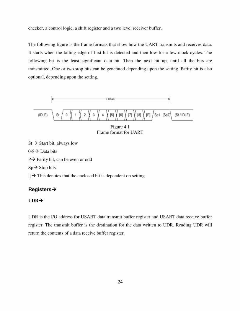
The following figure is the frame formats that show how the UART transmits and receives data.
It starts when the falling edge of first bit is detected and then low for a few clock cycles. The
following bit is the least significant data bit. Then the next bit up, until all the bits are
transmitted. One or two stop bits can be generated depending upon the setting. Parity bit is also
optional, depending upon the setting.
Figure 4.1
Frame format for UART
St � Start bit, always low
0-8� Data bits
P� Parity bit, can be even or odd
Sp� Stop bits
[]� This denotes that the enclosed bit is dependent on setting
Registers���� UDR����
UDR is the I/O address for USART data transmit buffer register and USART data receive buffer
register. The transmit buffer is the destination for the data written to UDR. Reading UDR will
return the contents of a data receive buffer register.
24
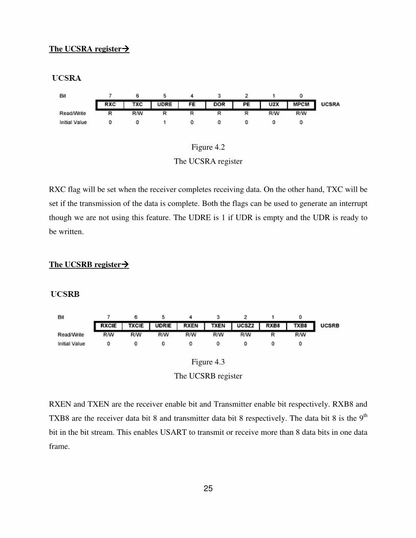
The UCSRA register����
Figure 4.2
The UCSRA register
RXC flag will be set when the receiver completes receiving data. On the other hand, TXC will be
set if the transmission of the data is complete. Both the flags can be used to generate an interrupt
though we are not using this feature. The UDRE is 1 if UDR is empty and the UDR is ready to
be written.
The UCSRB register����
Figure 4.3
The UCSRB register
RXEN and TXEN are the receiver enable bit and Transmitter enable bit respectively. RXB8 and
TXB8 are the receiver data bit 8 and transmitter data bit 8 respectively. The data bit 8 is the 9th
bit in the bit stream. This enables USART to transmit or receive more than 8 data bits in one data
frame.
25
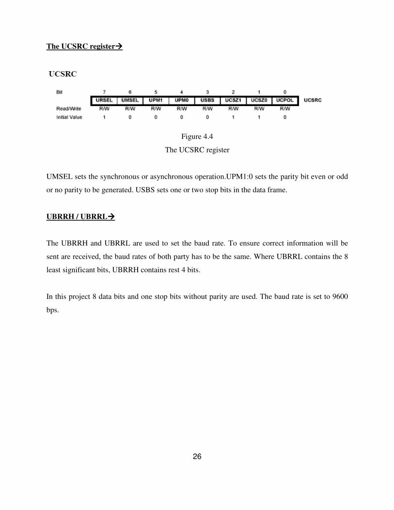
The UCSRC register����
Figure 4.4
The UCSRC register
UMSEL sets the synchronous or asynchronous operation.UPM1:0 sets the parity bit even or odd
or no parity to be generated. USBS sets one or two stop bits in the data frame.
UBRRH / UBRRL����
The UBRRH and UBRRL are used to set the baud rate. To ensure correct information will be
sent are received, the baud rates of both party has to be the same. Where UBRRL contains the 8
least significant bits, UBRRH contains rest 4 bits.
In this project 8 data bits and one stop bits without parity are used. The baud rate is set to 9600
bps.
26
CONCLUSION
Results and Discussion
Conclusion
Scope for further enhancement
CONCLUSION
Results and Discussion����
The velocity of the vehicle while moving straight is 8cm/s and it is 1.14rad/s while taking turn.
Wheel track of the vehicle is 12cm and wheel base is 18cm. width of wheel is 0.6cm and
material used for wheels and chassis is acrylic. In development stage, power supply was initially
given through 1.2V Ni-mH battery pack. Hence it is replaced with a 12V 7Ah Lead acid external
battery commonly used in portable UPS. To minimize slip of wheels, the motors are placed
along the centre of gravity of the vehicle. Initially TSOP IR sensors are used which are later
replaced with IR receivers as the prior give digital output and the latter give analog output. The
AGV was being controlled from Computer though Parallel port. From now on, it will be
controlled through Serial port. The controlling program used at the PC end was running in text
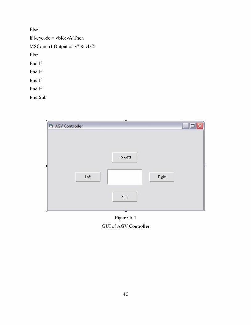
mode. A new program is developed to provide the users with a Graphical User Interface (GUI)
for better appearance and control. As each and every circuit is manual made, these are prone to
loose contact with a little endurance.
Conclusion����
Automated guided vehicles play an important role in flexible manufacturing systems. The project
mainly deals with building of an AGV and controlling it with computer. The simplified plant
layout is considered in the work and the vehicle is successfully controlled from one machine unit
to the other with machine number as the only input.
27
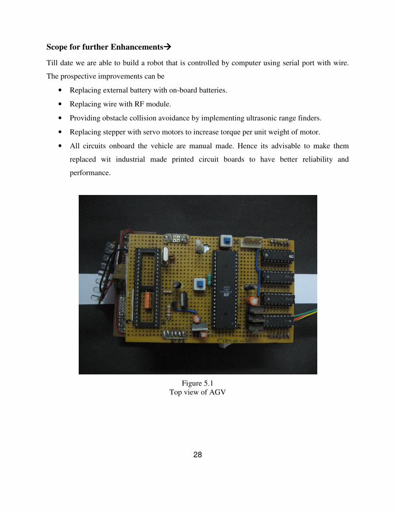
Scope for further Enhancements����
Till date we are able to build a robot that is controlled by computer using serial port with wire.
The prospective improvements can be
• Replacing external battery with on-board batteries.
• Replacing wire with RF module.
• Providing obstacle collision avoidance by implementing ultrasonic range finders.
• Replacing stepper with servo motors to increase torque per unit weight of motor.
• All circuits onboard the vehicle are manual made. Hence its advisable to make them
replaced wit industrial made printed circuit boards to have better reliability and
performance.
Figure 5.1
Top view of AGV
28
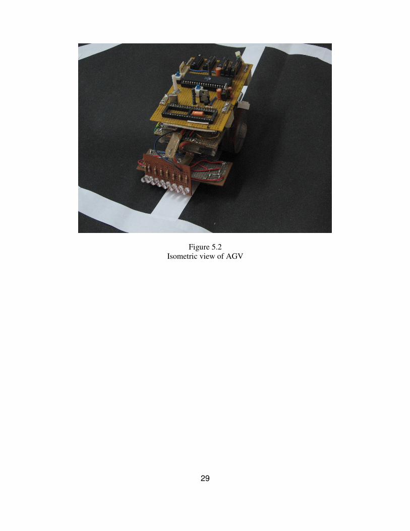
Figure 5.2
Isometric view of AGV
29

A: Program for the main Microcontroller
B: Program for the auxiliary Microcontroller
C: The control program for the PC
Appendix
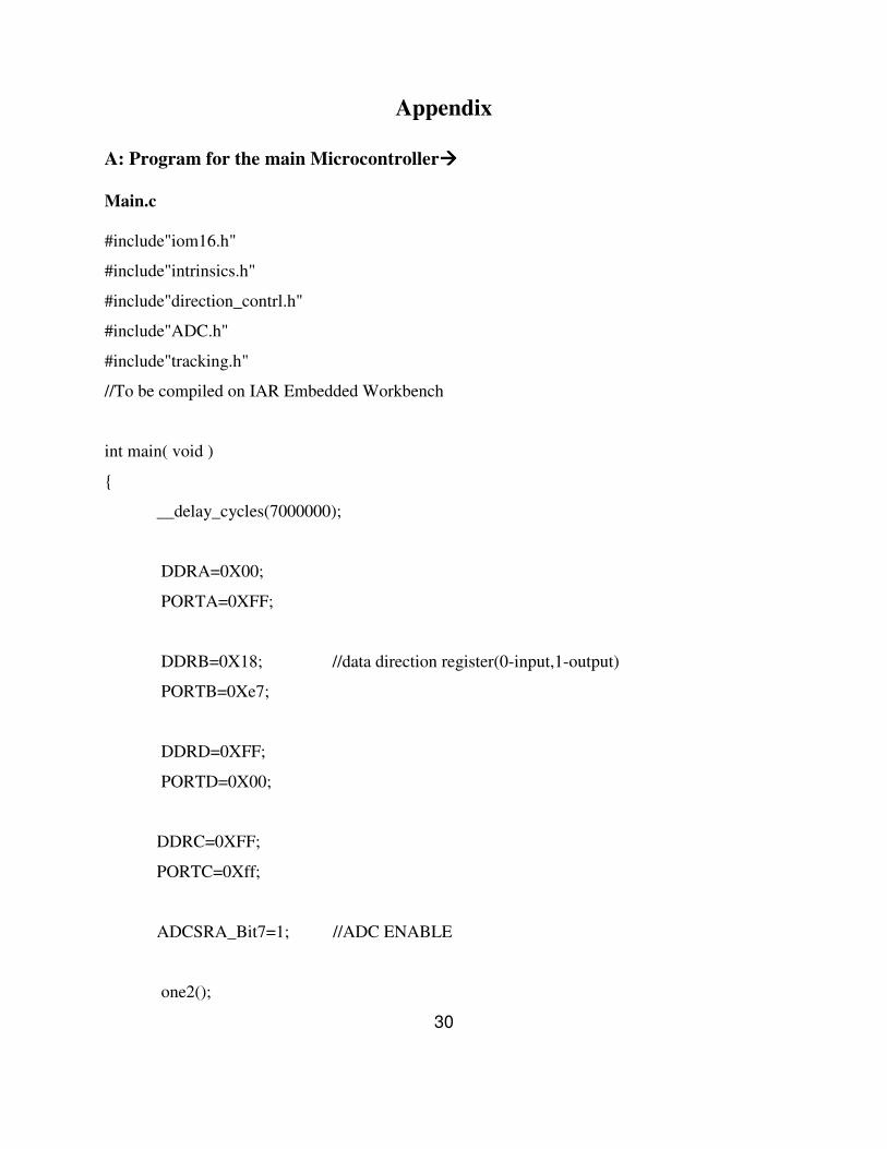
A: Program for the main Microcontroller����
Main.c
#include"iom16.h"
#include"intrinsics.h"
#include"direction_contrl.h"
#include"ADC.h"
#include"tracking.h"
//To be compiled on IAR Embedded Workbench
int main( void )
{
__delay_cycles(7000000);
DDRA=0X00;
PORTA=0XFF;
DDRB=0X18; //data direction register(0-input,1-output)
PORTB=0Xe7;
DDRD=0XFF;
PORTD=0X00;
DDRC=0XFF;
PORTC=0Xff;
ADCSRA_Bit7=1; //ADC ENABLE
one2();
30
while(1)
{
PORT.B=PINB;
if(PORT.PIN.B_1)
one2();
if(PORT.PIN.B_2)
one3();
}
return 0;
}
Direction_control.h
__near char x;
__near int p=0,q=0;
forward(void) /*FORWARD*/
{
char seq[4];
seq[0]=0x11;
seq[1]=0x88;
seq[2]=0x44;
seq[3]=0x22;
for(char i=0;i<2;i++)
{
PORTD=seq[x];
__delay_cycles(60000);
p=p+1;
q=q+1;
31
x=x+1;
if(x==4)
x=0;
}
}
right(void) /*RIGHT*/
{
char seq[4];
seq[0]=0x10;
seq[1]=0x80;
seq[2]=0x40;
seq[3]=0x20;
for(char i=0;i<2;i++)
{
PORTD=seq[x];
__delay_cycles(60000);
p=p+1;
x=x+1;
if(x==4)
x=0;
}
}
left(void) /*LEFT*/
{
char seq[4];
seq[0]=0x01;
seq[1]=0x08;
seq[2]=0x04;
32

seq[3]=0x02;
for(char i=0;i<2;i++)
{
PORTD=seq[x];
__delay_cycles(60000);
q=q+1;
x=x+1;
if(x==4)
x=0;
}
}
ADC.h
char left1,left2,right1,right2;
read_left1()
{
ADMUX_Bit6=1; //AREF=AVCC
ADMUX_Bit5=1; //LEFT ADJUST
ADMUX_Bit0=0; //SELECT INPUT
ADMUX_Bit1=0;
ADCSRA_Bit6=1; //START CONVERSION
check: if(ADCSRA_Bit4==1) //CHECK FOR END OF CONVERSION
left1=ADCH; //READ DATA
else
goto check;
ADCSRA_Bit4=0; //CLEAR INTERRUPT
}
33

read_left2()
{
ADMUX_Bit6=1; //AREF=AVCC
ADMUX_Bit5=1; //LEFT ADJUST
ADMUX_Bit0=1; //SELECT INPUT
ADMUX_Bit1=0;
ADCSRA_Bit6=1; //START CONVERSION
check: if(ADCSRA_Bit4==1) //CHECK FOR END OF CONVERSION
left2=ADCH; //READ DATA
else
goto check;
ADCSRA_Bit4=0; //CLEAR INTERRUPT
}
read_right1()
{
ADMUX_Bit6=1; //AREF=AVCC
ADMUX_Bit5=1; //LEFT ADJUST
ADMUX_Bit0=0; //SELECT INPUT
ADMUX_Bit1=1;
ADCSRA_Bit6=1; //START CONVERSION
check: if(ADCSRA_Bit4==1) //CHECK FOR END OF CONVERSION
right1=ADCH; //READ DATA
else goto check;
ADCSRA_Bit4=0; //CLEAR INTERRUPT
}
34

read_right2()
{
ADMUX_Bit6=1; //AREF=AVCC
ADMUX_Bit5=1; //LEFT ADJUST
ADMUX_Bit0=1; //SELECT INPUT
ADMUX_Bit1=1;
ADCSRA_Bit6=1; //START CONVERSION
check: if(ADCSRA_Bit4==1) //CHECK FOR END OF CONVERSION
right2=ADCH; //READ DATA
else
goto check;
ADCSRA_Bit4=0; //CLEAR INTERRUPT
}
readall()
{
read_left1();
read_right1();
read_left2();
read_right2();
}
Tracking.h
int a=0,b=385,r=503;
__near union abc
{
char B;
struct cba
35
{
char B_0:1;
char B_1:1;
char B_2:1;
char B_3:1;
char B_4:1;
char B_5:1;
char B_6:1;
char B_7:1;
}PIN;
}PORT;
one2()
{
a=0;
PORT.B=PINB;
while(1)
{
readall();
while((left1<200)&&(right1<200)&&(a<b))
{
readall();
forward();
PORT.B=PINB;
a++;
}
while((left1>200)&&(right1<200)&&(a<b))
{
readall();
left();
PORT.B=PINB;
36
a++;
}
while((left1<200)&&(right1>200)&&(a<b))
{
readall();
right();
PORT.B=PINB;
a++;
}
while((left1>200)&&(right1>200)&&(a<b))
{
readall();
right();
PORT.B=PINB;
a++;
}
PORT.B=PINB;
if(a>=b)
break;
}
}
one3()
{
a=0;
PORT.B=PINB;
while(1)
{
readall();
while((left1<200)&&(right1<200)&&(a<r))
37
{
readall();
forward();
PORT.B=PINB;
}
while((left1>200)&&(right1<200)&&(a<r))
{
readall();
left();
PORT.B=PINB;
}
while((left1<200)&&(right1>200)&&(a<r))
{
readall();
right();
PORT.B=PINB;
}
while((left1>200)&&(right1>200)&&(a<r))
{
readall();
forward();
PORT.B=PINB;
}
PORT.B=PINB;
if(a>=r)
break;
}
}
38

B: Program for the auxiliary Microcontroller����
Main.c
//To be Compiled on CodeVision C compiler
#include <mega16.h>
#include <stdio.h>
void USART_INIT(void);
unsigned char usart_receive(void);
void main(void)
{
unsigned char ch;
USART_INIT();
while(UCSRA.7==0)
{
ch=usart_receive();
switch(ch)
{
case 'w':
PORTB=0X04;
break;
case 's':
PORTB=0X07;
break;
case 'a':
PORTB=0X05;delay
break;
case 'd':
PORTB=0X06;
break;
39
default:
break;
}
}
}
void USART_INIT(void)
{
UCSRA=0x20;
UCSRB=0x18;
UCSRC=0x8E;
UBRRH=0X00;
UBRRL=0x17;
DDRB=0X07;
PORTB=0X07;
}
unsigned char usart_receive(void)
{
while(UCSRA.7==0)
;
return UDR;
}
40

C: The control program for the PC����
(To be compiled on Visual Basic)
Private Sub Form_Load()
MSComm1.CommPort = 4
MSComm1.Settings = "9600,N,8,1"
MSComm1.PortOpen = True
End Sub
Private Sub Forward_Click()
MSComm1.Output = "w" & vbCr
End Sub
Private Sub Frame1_DragDrop(Source As Control, X As Single, Y As Single)
End Sub
Private Sub Left_Click()
MSComm1.Output = "a" & vbCr
End Sub
Private Sub Right_Click()
MSComm1.Output = "d" & vbCr
End Sub
Private Sub Stop_Click()
MSComm1.Output = "s" & vbCr
End Sub
41

Private Sub Text1_KeyDown(keycode As Integer, shift As Integer)
If keycode = vbKeyA Then
MSComm1.Output = "a" & vbCr
Else
If keycode = vbKeyS Then
MSComm1.Output = "s" & vbCr
Else
If keycode = vbKeyD Then
MSComm1.Output = "d" & vbCr
Else
If keycode = vbKeyW Then
MSComm1.Output = "w" & vbCr
Else
End If
End If
End If
End If
End Sub
Private Sub Text1_Keyup(keycode As Integer, shift As Integer)
If keycode = vbKeyW Then
MSComm1.Output = "r" & vbCr
Else
If keycode = vbKeyS Then
MSComm1.Output = "t" & vbCr
Else
If keycode = vbKeyD Then
MSComm1.Output = "u" & vbCr
42
Else
If keycode = vbKeyA Then
MSComm1.Output = "v" & vbCr
Else
End If
End If
End If
End If
End Sub
Figure A.1
GUI of AGV Controller
43
REFERENCE
1. Jaworska, Irena, Laski, Tomasz “Student-oriented program for introductory robotics
education” Robotics and Autonomous Systems Volume 8, Issue 4, 1991, Pages 275-280.
2. Joseph J. M. Evers and Stijn A. J. Koppers, “Automated guided vehicle traffic control at
a container terminal” Transportation Research Part A: Policy and Practice Volume 30,
Issue 1 , January 1996, Pages 21-34
3. Vladimir R.Milai and Goran D.Putnik,” Steering rules for AGV based on primitive
function and elementary movement control”, Robotics and Computer-Integrated
Manufacturing Volume 5, Issues 2-3 , 1989, Pages 249-254
4. Michiko Watanabe,Masashi Furukawa,and Yukinori Kakazu, “Intelligent AGV driving
toward an autonomous decentralized manufacturing system”, Robotics and Computer-
Integrated Manufacturing Volume 17, Issues 1-2 , February 2001, Pages 57-64(problems
in navigation)
5. Stuart J. Russell, “Prior knowledge and autonomous learning”, Robotics and
Autonomous Systems Volume 8, Issues 1-2 , November 1991, Pages 145-159
6. Hofner.C, Schmidt.G, “Path planning and guidance techniques for an autonomous mobile
cleaning robot”, Intelligent Robots and Systems '94. 'Advanced Robotic Systems and the
Real World', IROS '94. Proceedings of the IEEE/RSJ/GI International Conference on
Volume 1, 12-16 Sept. 1994 Page(s):610 - 617 vol.1
7. Enxiu Shi, Yumei Huang, Yizhong Lin, “Research on the method of composite
navigation for AGV”, Fifth World Congress on Intelligent Control and Automation, 15-
19 June 2004, IEEE.
8. Andersen.N, Henriksen.L, Ravn.O,” Design of navigation and control for an AGV”,
Intelligent Autonomous Vehicles 1995. Postprint Volume from the 2nd IFAC
Conference, 1995, 175-80
9. Dr. T. Tempelmeier, “Microprocessors in factory automation — A case study of an
automated guided vehicle system and its integration into a hierarchical control structure”,
Microprocessing and Microprogramming Volume 18, Issues 1-5 , December 1986, Pages
647-656
10. Yvan J. Beliveau,Jeffrey E. Fithianc, and Michael P. Deisenrothd, “Autonomous vehicle
navigation with real-time 3D laser based positioning for construction”, Automation in
Construction Volume 5, Issue 4 , October 1996, Pages 261-272
11. Steven H. -Y. Lai, “On the design of AGV travel mechanisms”, Computers & Industrial
Engineering Volume 23, Issues 1-4 , November 1992, Pages 181-185
12. http://www.automaticguidedvehicles.com/info/articles.htm
45