Embed Size (px)
Citation preview
DESIGN AND DEVELOPMENT OF A CONCENTRIC
DRIVEN SERIAL CHAIN MANIPULATOR
A THESIS SUBMITTED IN PARTIAL FULFILLMENT OF
THE REQUIREMENTS FOR THE DEGREE OF
BACHELOR OF TECHNOLOGY IN
MECHANICAL ENGINEERING
BY
PRADEEPTA KUMAR SAHOO
108ME076
DEPARTMENT OF MECHANICAL ENGINEERING
NATIONAL INSTITUTE OF TECHNOLOGY
ROURKELA 769008
DESIGN AND DEVELOPMENT OF A CONCENTRIC
DRIVEN SERIAL CHAIN MANIPULATOR
A THESIS SUBMITTED IN PARTIAL FULFILLMENT OF
THE REQUIREMENTS FOR THE DEGREE OF
BACHELOR OF TECHNOLOGY IN
MECHANICAL ENGINEERING
By
Pradeepta Kumar Sahoo
108ME076
Under the guidance of
Prof. B.B. Biswal Department of Mechanical Engineering
National Institute of Technology, Rourkela
DEPARTMENT OF MECHANICAL ENGINEERING
NATIONAL INSTITUTE OF TECHNOLOGY
ROURKELA 769008
i
DEPARTMENT OF MECHANICAL ENGINEERING
NATIONAL INSTITUTE OF TECHNOLOGY
ROURKELA 769008
CERTIFICATE
This is to certify that the thesis entitled “DESIGN AND DEVELOPMENT OF A
CONCENTRIC DRIVEN SERIAL CHAIN MANIPULATOR” submitted by
Pradeepta Kumar Sahoo (Roll Number: 108ME076) in partial fulfillment of the
requirements for the award of Bachelor of Technology in the Department of
Mechanical Engineering, National Institute of Technology, Rourkela, is an authentic
work carried out under my supervision and guidance.
To the best of my knowledge, the matter embodied in the thesis has not been
submitted elsewhere for the award of any degree.
Place: Rourkela Prof. B. B. Biswal
Date: Department of Mechanical Engineering
National Institute of Technology
Rourkela-769008
ii
A C K N O W L E D G E M E N T
It gives me immense pleasure to express my deep sense of gratitude to my
supervisor, Prof. B. B. Biswal, for his invaluable guidance and motivation during
the course of this project work. He was a constant source of inspiration and above all
his ever-cooperating attitude enabled me in carrying out all the initial surveys,
design evaluation, planning and also to bring up this thesis in the present form.
I am extremely thankful to Prof. K. P. Maity, Head of the Department, Mechanical
Engineering, for providing all kinds of possible help and advice during the course of
this work. I am greatly thankful to all my well wishers, classmates and friends for
their inspiration and help.
Place: Rourkela Pradeepta Kumar Sahoo
Date: B.Tech, Roll No: 108ME076
Department of Mechanical Engineering
National Institute of Technology, Rourkela
iii
ABSTRACT
Now-a-days, industrial robot is been custom made by various companies which serves
companies of different sectors in fulfilling the very specific demand, such as welding,
painting, fabricating microchips, etc. Usually these robots are provided with actuators at
each joint for simplicity and reliability. This paper introduces a new concept of a
concentric driven serial chain manipulator where only one motor is used to supply the
power required by the robot to do all the required motion or it’s a uni-motor robot or
manipulator.
The sole idea is to power the manipulator by a single servo motor, which will enable
motion to each joint, but one at a time. An auto clutch system is designed, so that the
requirement of additional costly electromagnetic clutches is totally eliminated. Such a
design configuration of the manipulator has an obvious advantage on design reliability,
cost saving and easy maintenance. This project includes a new mechanical drive to
achieve the required power transmission and subsequently new locking design for the
joints. The manipulator is modeled and simulated over CATIA V5 R21 software to test the
kinematics of the manipulator components.
iv
CONTENT
CHAPTER1. Introduction…………………………………………………………..1
CHAPTER2. Literature survey……………………………………………….……..3
CHAPTER3. The industrial robot…………………………………………….……..5
3.1 The industrial robot……………………………………….………5
3.2 Important terms……………………………………….……..……6
3.3 Types of robots………………………………………………..…..9
3.3.1 Spherical base robot……………………………………….……9
3.3.2 Parallelogram robots (delta parallel robots)…………….…..…11
3.3.3 Cylindrical robots………………………………………..…..…13
CHAPTER4. Objective of the research work……………………………………….15
CHAPTER5. Design consideration…………………………………………….……16
5.1 Serial configuration…………………………………………...…..16
5.2 Parallel configuration………………………………………..……17
CHAPTER6. Design conceptualization……………………………………………..18
6.1 Power train……………………………………………………..….19
6.1.1 Central gear hub…………………………………………………19
6.2 Arm sweep …………………………………………………….…..21
6.2.1 Arm actuation……………………………………………………22
6.3 Shoulder swivel…………………………………………………….23
6.3.1 Shoulder actuation……………………………………………….24
6.4 Elbow extension……………………………………………………25
6.4.1 Elbow actuation………………………………………….……….26
v
6.5 Arm actuation mechanism and auto clutching concept…………27
6.5.1 Arm actuation mechanism………………………………………27
6.5.2 Auto clutching …………………………………………….…….28
6.5.2.1 Shoulder clutching……………………………………..……..30
6.5.2.2 Elbow clutching…………………………………………..……31
6.6 Gear shifter…………………………………………………………32
6.6.1 Components of gear shifter………………………………………32
CHAPTER7 Conclusion………………………………………………………………34
CHAPTER8 Reference……………………………………………………..…………35
vi
LIST OF FIGURES
Fig.3.1. Industrial robot
Fig.3.2 Spherical robot- world coordinate and work volume
Fig 3.3 Schematic of the delta robot (from US patent No.4976582)
Fig.3.4 Cylindrical robots
Fig.3.5Cylindrical robot work volume
Fig.5.1 Serial configuration
Fig.5.2 Parallel configuration
Fig.6.0 3-D model of the manipulator
Fig.6.1 Central gear hub
Fig.6.2 Arm sweep action
Fig.6.3 Arm actuation
Fig.6.4 Shoulder swivel action
Fig.6.5 Shoulder actuation
Fig.6.6 Elbow extension action
Fig.6.7 Elbow actuation
Fig.6.8 Arm actuation mechanism
Fig.6.9 Auto clutching
Fig.6.10 Shoulder clutching
Fig.6.11 Elbow clutching
Fig.6.12 Gear shifter

1 | P a g e
CHAPTER 1
INTRODUCTION
A mechanical arm is robotic, usually programmable, with similar functions to a
human arm. The links of such a manipulator are connected by joints allowing either
rotational motion (such as in an articulated robot) or translational (linear)
displacement. The links of the manipulator can be considered to form a kinematic chain.
The business end of the kinematic chain of the manipulator is called the end effector and
it is analogous to the human hand. The end effector can be designed to perform any
desired task such as welding, gripping, spinning etc., depending on the application. For
example robot arms in automotive assembly lines perform a variety of tasks such
as welding and parts rotation and placement during assembly.
According to Issac Asimov, a robot must obey the three laws:
A robot must not harm human body through its action or inaction.
A robot must always obey a human being it conflicts with the first law.
A robot must protect itself from harm unless it is in conflict with the first and
second law.
These laws are the most basic laws in the field of robotics. They have great significance
in designing robots for various purposes.
In most contemporary robots, it s observed that each joint of the robot is actuated by an
independent motor. This arrangement has an obvious advantage in terms of speed of
2 | P a g e
operation. However, placing a motor for each joint largely increases the initial cost of the
robot. Further, due to heavy maintenance of these motors, the life cycle cost is high. The
concept of uni-motor driven robot is more relevant to low end applications as an
economical alternative to contemporary robots. In this type of robot a single motor is
used to actuate all the joints of the motor to each of the joints. Uni-motor driven robot
will be a series manipulator where only one joint can be actuated at a time. This type of
robot has an obvious disadvantage of being slower than contemporary robots. However,
the elimination of motors substantially reduces the initial cost as well as maintenance.
This makes the uni-motor driven robot apt for educational applications as well as
applications where large investment is not desirable.
As now a day’s robots are been used or even have become a necessity at some places, a
lot of attention is been given to this field lately. Engineers and scientist are working hard
to design and develop easy to make and cheaper efficient robots to make our life easier.
The project work is mainly concerned with the design of the power transmission drive of
the robot. The robot will be driven by a single servo motor, and the motion will be
transmitted to different joints through a gear train. The concept for the gear train has been
developed and modeled to explain the working of each joint. CATIA v5 R21 software is
used to model the robot, and simulate the kinematic behavior of the manipulator.

3 | P a g e
CHAPTER 2
LITERATURE SURVEY
Year Author Journal,vol.
page
Theoretical/
analytical/
experimenta
l/
stastical
Method
used
Material &
machine use or
source of data
(for analytical)
Major
Findings
1987 K C
Gupta
IEEE,55 Theoretical
&
mathematic
al
Not
specified
Data collected
from existing
robots
configurations
For computer
control of
Robot wrists,
closed form
equations are
required. So it
was derived
for orthogonal
& non
orthogonal co-
intersecting
axes.
2003 Nilanjan
Sarkar,
Xiaopin
g Yun,
and
Vijay
Kumar
IEEE,6 Theoretical
&
mathematic
al
Vector
Analysis
Robot arm
maintaining
rolling contact
Using Control
of a Single
Robot in a De
centralized
Multi-Robot
System
2006 Eftychio
s G.
Christof
orou,Ni
kolaoa
V.
tsekos
IEEE
Internationa
l
Conference
on Robotics
&
Automation
Case study Not
specified
Data collected
of compatible
arm with
remotely-
actuated joints
Joint
transmission
through
various types
of u-joints
Year Author Journal,v
ol. page
Theoretical/an
alytical/
experimental/
stastical
Method
used
Material &
machine use or
source of data
(for analytical)
Major
Findings
4 | P a g e
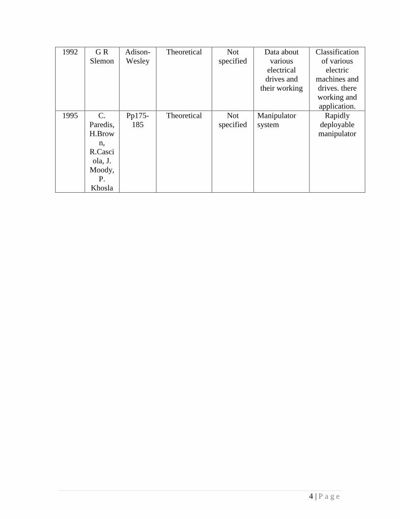
1992 G R
Slemon
Adison-
Wesley
Theoretical Not
specified
Data about
various
electrical
drives and
their working
Classification
of various
electric
machines and
drives. there
working and
application.
1995 C.
Paredis,
H.Brow
n,
R.Casci
ola, J.
Moody,
P.
Khosla
Pp175-
185
Theoretical Not
specified
Manipulator
system
Rapidly
deployable
manipulator
5 | P a g e
CHAPTER 3
THE INDUSTRIAL ROBOT
3.1 The Industrial robot:
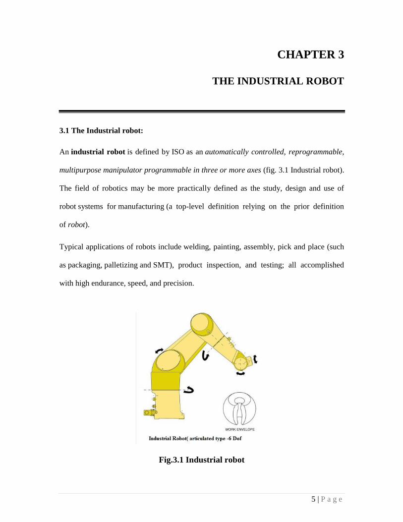
An industrial robot is defined by ISO as an automatically controlled, reprogrammable,
multipurpose manipulator programmable in three or more axes (fig. 3.1 Industrial robot).
The field of robotics may be more practically defined as the study, design and use of
robot systems for manufacturing (a top-level definition relying on the prior definition
of robot).
Typical applications of robots include welding, painting, assembly, pick and place (such
as packaging, palletizing and SMT), product inspection, and testing; all accomplished
with high endurance, speed, and precision.
Fig.3.1 Industrial robot
6 | P a g e
3.2 Important terms which define robot anatomy.
Axis/axes – An axis is a line across which a rotating body turns. Two axes are required to
reach any point in a straight plane, while three axes (X Y Z) are needed to reach any
point in space. Three further axes (roll, pitch and yaw) are needed to control the
orientation of theend of the robot arm or wrist.
End effector – Also known as end of arm tooling, this is the ‘hand’ attached to the end of
the robot arm or wrist. End effectors include grippers, vacuum cups, spray guns, welding
tools and electro-magnetic pick-ups, their performance being vital to precision and
repeatability.
Degrees of freedom – this is the number of independent movements the end effector can
make along the axes of its coordinate system. For example, movement along the X Y Z
coordinates only constitutes 3 DoF, whilst adding rotation around the Z axis equals 4
DoF. This term is often confused with degrees of mobility (see below).
Degrees of mobility – while DoF are often incorrectly determined by simply counting
the number of independent joints on the robot, this is more accurately expressed as
degrees of mobility (DoM). Thus, an industrial robot has a maximum of 6 DoF, but might
actually have, say, 9 DoM.
Kinematics – is the actual arrangement of joints/axes and rigid links in the robot, as well
as being the study of motion in robotics. Common robot kinematics, or configurations,
include Cartesian, Articulated, Parallel and SCARA.
Manipulator – this refers to the arm mechanism, created from a sequence of joint and
linkage combinations, including the wrist. Confusingly, it is often used to describe the
robot itself, minus the power supply and controller.
7 | P a g e
Joints – robot joints are described as either rotational or translational. Rotational joints
have a rotary action along the joint axis and are also referred to as revolute. Translational
joints have a linear or sliding motion along the joint axis and are also known as prismatic.
Actuators – also referred to as drives, these are devices that convert electrical, hydraulic
and pneumatic energy into robot motion. Nowadays, actuators are typically fast, accurate
AC servo drives, while the robot base rotates using a harmonic drive or, less commonly,
ring gear.
Work envelope – this is the total volume of space that the end effector of the
manipulator can reach and is also known as workspace and work volume. The size and
shape of the work envelope is determined by the robot kinematics and the number of
DoF; it should be large enough to accommodate all the points the end effector needs to
reach.
Having got to grips with the anatomical terms used in connection with industrial robots,
we should next consider the operating and performance parameters against which any
particular configuration and type is specified:
Payload (kg) – Maximum load or carrying capacity, including weight of the end effector.
Reach (mm) – The maximum distance a robot can extend its arm to perform a task.
Speed (mm/sec) –Hhow fast a robot can position its end effector or rotate an axis
(deg/sec).
Acceleration (mm/sec) – Defines how quickly an axis can accelerate to top speed.
Accuracy (± mm) – How closely a robot can move to specified place in the work
envelope.
Repeatability (± mm) – How precisely a robot can return repeatedly to a given position.

8 | P a g e
Mounting – Robots can also be ceiling or wall mounted, freeing up effective workspace.
Footprint (m2) – Installation space required, often minimised by overhead or wall
mounting.
Cycle Time (secs) – Cumulative time for completing one full set of process operations.
9 | P a g e
3.3 Types of robots:
3.3.1. Spherical base robot:
Spherical bases of the robots make them capable of working in a spherical space. Though
the workspace cannot be more than a three dimensional one but with the increasing
number of the revolute joints the arm movements of the robot can become more
sophisticated. Spherical Bases Robots, as the name says, work in a space defined by the
intersection of spherical volumes. With wide range of possibilities of complex
movements robots with spherical bases find application in many industrial processes.
Construction of the Base Structure
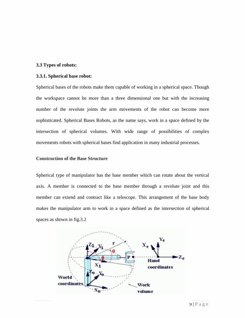
Spherical type of manipulator has the base member which can rotate about the vertical
axis. A member is connected to the base member through a revolute joint and this
member can extend and contract like a telescope. This arrangement of the base body
makes the manipulator arm to work in a space defined as the intersection of spherical
spaces as shown in fig.3.2

10 | P a g e
Fig.3.2 Spherical Robot-world coordinates and work space
The spherical base has the same, three, numbers of joints as the other three dimensional
robot bases has. Two joints are revolute joints and the remaining is a prismatic joint such
that the arm of the robot can extend and retract. The end effectors of the robot are
mounted on this telescopic arm. The two revolute joint movements can be actuated by
direct coupling with the servo motors and the telescopic arm movement can be actuated
by a rack and pinion arrangement. Spherical base has three degrees of freedom and three
variables to be controlled to operate it.
Reach and Workspace of Spherical Base Robot
Reach of a robot is the limits to which its end effectors can approach the work points. For
the spherical robots the reach of its end effectors is determined by the limits of the motion
of the three joints of the base. For such type of base of the robots the reach of the end
effectors of the robot is a sphere. The radius of this sphere is dependent on the maximum
extension of the telescopic arm.
The workspace of the spherical base robots is the volume intersection of the two
concentric spheres. The dimensions of the external sphere are equal to the maximum
limits of the joint movements and the radius of the inner sphere is determined by the
minimum limits of the joint movements which are in turn governed by design constraints.
The range of rotation of the revolute joint at base and between the base member and the
arm determines the sector of the sphere that can be covered; and the range of movement
11 | P a g e
of the telescope arm determines the range of the radius of the spherical volume of
intersection.
3.3.2. Parallelogram robots (delta parallel robot):
The Delta robot is a parallel robot, i.e. it consists of multiple kinematic
chains interconnecting the base with the end-effector. The robot can also be seen as a
spatial generalization of a four-bar linkage as shown in fig. 3.3.
The key concept of the Delta robot is the use of parallelograms. These parallelograms
restrict the movement of the end platform to pure translation (only movement in the X, Y
or Z direction). The robot's base is mounted above the workspace and all the actuators are
located on it. From the base, three middle jointed arms extend. The ends of these arms are
connected to a small triangular platform. Actuation of the input links will move the
triangular platform along the X, Y or Z direction. Actuation can be done with linear or
rotational actuators, with or with our reductions (direct drive). Since the actuators are all
located in the base, the arms can be made of a light composite material. As a result of
this, the moving parts of the Delta robot have a small inertia. This allows for very high
speed and high accelerations. Having all the arms connected together to the end-effector
increases the robot stiffness, but reduces its working volume.

12 | P a g e
Fig.3.3 Schematic of the Delta robot (from US patent No. 4,976,582)
The version developed by Reymond Clavel has four degrees of freedom: three
translations and one rotation. In this case a fourth leg extends from the base to the middle
of the triangular platform giving to the end effector a fourth, rotational degree of freedom
around the vertical axis.
Currently other versions of the delta robot have been developed:
Delta with 6 degrees of freedom: Developed by the company Fanuc, on the end
effector is placed a serial kinematic of 3 rotational degrees of freedom
Delta with 4 degrees of freedom: Developed by the company Adept, instead of
having a forth leg coming in the middle of the end-effector, it has directly 4
parallelogram connected to the end-platform
Delta direct drive: A 3 degrees of freedom Delta having the motor directly connected
to the arms. Accelerations can be very high, from 30 up to 100 g.
Pocket Delta: Developed by the company Asyril, a version of the delta Robot adapted
for high-precision applications.
13 | P a g e
Delta Cube: Developed by the LSRO, a Delta robot built in a monolithic design,
having flexure-hinges joints. This robot is adapted for ultra-high-precision
applications.
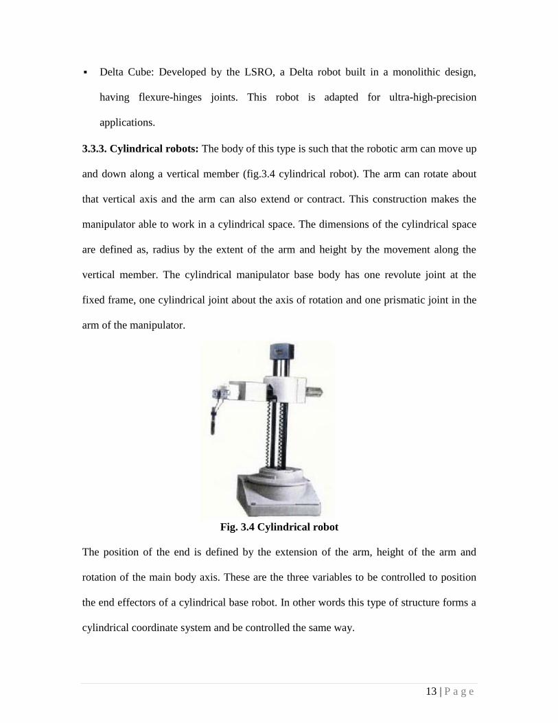
3.3.3. Cylindrical robots: The body of this type is such that the robotic arm can move up
and down along a vertical member (fig.3.4 cylindrical robot). The arm can rotate about
that vertical axis and the arm can also extend or contract. This construction makes the
manipulator able to work in a cylindrical space. The dimensions of the cylindrical space
are defined as, radius by the extent of the arm and height by the movement along the
vertical member. The cylindrical manipulator base body has one revolute joint at the
fixed frame, one cylindrical joint about the axis of rotation and one prismatic joint in the
arm of the manipulator.
Fig. 3.4 Cylindrical robot
The position of the end is defined by the extension of the arm, height of the arm and
rotation of the main body axis. These are the three variables to be controlled to position
the end effectors of a cylindrical base robot. In other words this type of structure forms a
cylindrical coordinate system and be controlled the same way.
14 | P a g e
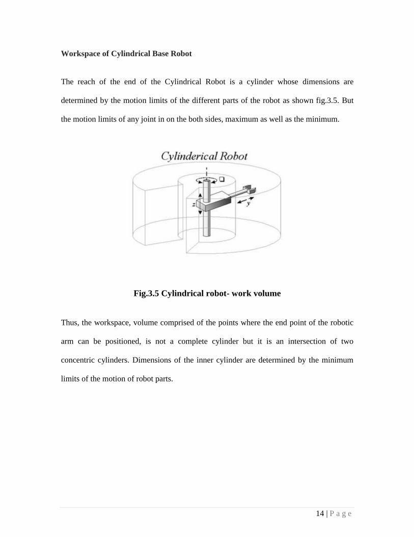
Workspace of Cylindrical Base Robot
The reach of the end of the Cylindrical Robot is a cylinder whose dimensions are
determined by the motion limits of the different parts of the robot as shown fig.3.5. But
the motion limits of any joint in on the both sides, maximum as well as the minimum.
Fig.3.5 Cylindrical robot- work volume
Thus, the workspace, volume comprised of the points where the end point of the robotic
arm can be positioned, is not a complete cylinder but it is an intersection of two
concentric cylinders. Dimensions of the inner cylinder are determined by the minimum
limits of the motion of robot parts.
15 | P a g e
CHAPTER 4
OBJECTIVES OF THE RESEARCH WORK
Design and development of a concentric driven serial chain manipulator arm.
As mentioned in the first chapter, the sole objective of this project report is to develop a
concept where a single servo motor will serve as the sole driving source for all the
revolute joints of the manipulator. Along with this, it is to be kept in mind to develop a
cheaper, efficient and reliable design for the robot manipulator.
The objectives are listed below:
To design the serial chain manipulator.
To design a gear transmission for the concentric motoring action for the actuation
of each joint.
To design a new clutching concept for the manipulator.
16 | P a g e
CHAPTER 5
DESIGN CONSIDERATION
This project deals about a new concept of the concentric driven manipulator arm instead
of the conventional method. There are generally two kinds of single actuator robots as
follows:
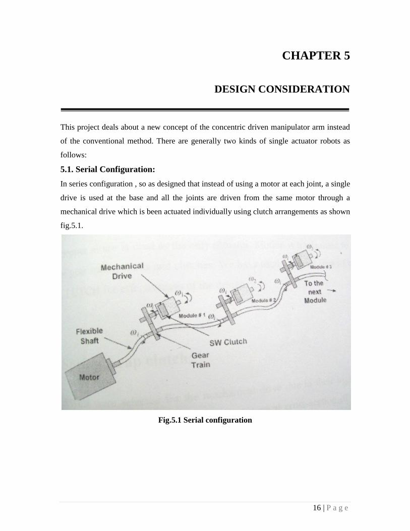
5.1. Serial Configuration:
In series configuration , so as designed that instead of using a motor at each joint, a single
drive is used at the base and all the joints are driven from the same motor through a
mechanical drive which is been actuated individually using clutch arrangements as shown
fig.5.1.
Fig.5.1 Serial configuration

17 | P a g e
5.2. Parallel Configuration:
In the parallel configuration, the whole system works on a single motor but instead using
the previous configuration the single drive is connected to a distributor as shown fig.5.2.
The main difference between the two configuration is that instead of a single rotating
shaft , we have a shaft for every concerned joints.
Fig. 5.2 Parallel Configuration
For simplicity and better effectiveness the series configuration is adopted. The clutch
system is re-designed where no electromagnetic actuation is required or other types of
actuation is required instead these clutches are based on simple fundamentals of
mechanical engineering.
Servo motors are used for a better point to point accurate motion of the central shaft
which delivers the main motion to every joint present.
18 | P a g e
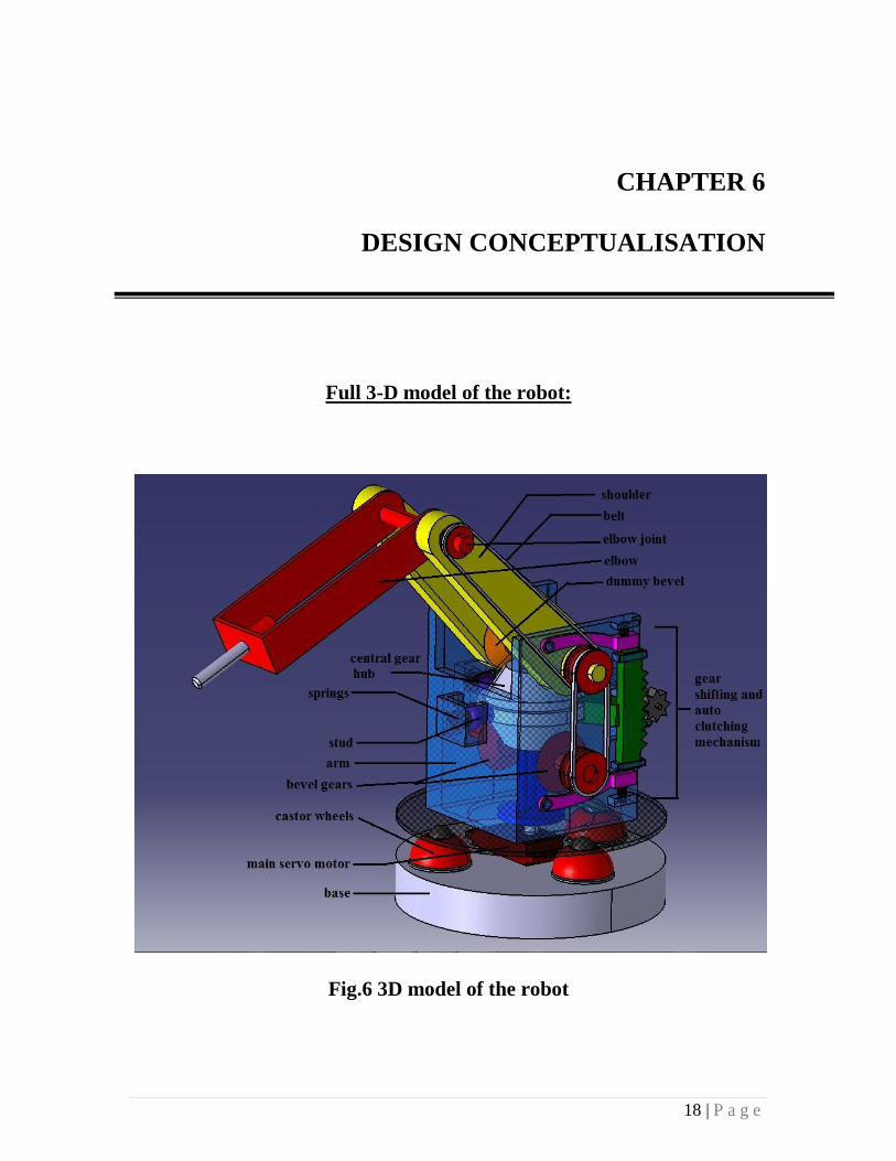
CHAPTER 6
DESIGN CONCEPTUALISATION
Full 3-D model of the robot:
Fig.6 3D model of the robot

19 | P a g e
6.1 Power train:
As the whole idea of the power transmission from a single servo motor is new, the
concept requires a custom made power train to transmit the required motion from the
motor to the individual revolute joints which is governed by a series of gear shifting
procedures.
Components:
6.1.1. Central gear Hub:
It is a combination of a central circular disc with rough outer surface , so as it could
easily grab the clutch during the clutching action when the manipulator is in its neutral
position which ensures the movement of the arm. Along with this, there are two bevel
gears as shown in fig.6.1
Fig 6.1 Central gear hub
20 | P a g e
The upper bevel gear comes into play when we need to swivel the shoulder, by
transmitting the rotary motion of the servo motor to the consequent bevel gear actuating
the shoulder.
The lower bevel gear comes into play when we need to extend the elbow, which is again
transmitted to the revolute joint of the elbow via two pulleys and belt system.
Rubber belts are used for better transmission of motion or power and to have minimum
back lash.
The central gear hub consists of three through holes, through which the three shafts from
the servo motor drives the central gear hub as well as guide the central gear hub to move
up and down to three transmitting positions with the manipulator.

21 | P a g e
6.2 ARM SWEEP:
Arm sweep (fig.6.2) is the motion of the whole manipulator along the axis of rotation of
the servo motor which serves as the driving motor for all the three revolute joints of this
articulated manipulator. This motor enables the manipulator to move through an angle
from 0-360 degrees, for this a continuous rotation servo motor is used, giving the
manipulator the ability to reach every corner around it.
Fig.6.2 Arm Sweep
22 | P a g e
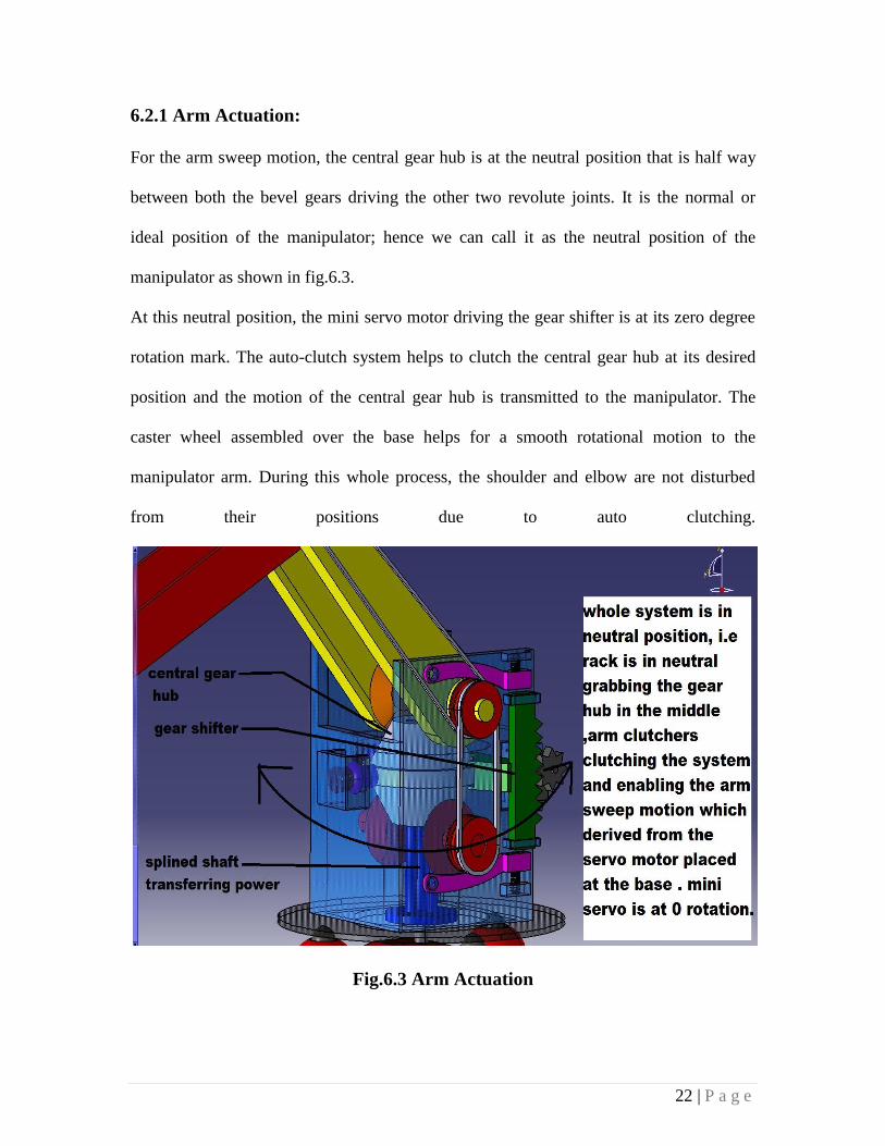
6.2.1 Arm Actuation:
For the arm sweep motion, the central gear hub is at the neutral position that is half way
between both the bevel gears driving the other two revolute joints. It is the normal or
ideal position of the manipulator; hence we can call it as the neutral position of the
manipulator as shown in fig.6.3.
At this neutral position, the mini servo motor driving the gear shifter is at its zero degree
rotation mark. The auto-clutch system helps to clutch the central gear hub at its desired
position and the motion of the central gear hub is transmitted to the manipulator. The
caster wheel assembled over the base helps for a smooth rotational motion to the
manipulator arm. During this whole process, the shoulder and elbow are not disturbed
from their positions due to auto clutching.
Fig.6.3 Arm Actuation
23 | P a g e
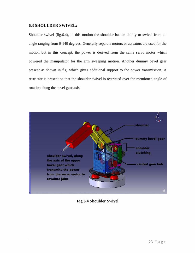
6.3 SHOULDER SWIVEL:
Shoulder swivel (fig.6.4), in this motion the shoulder has an ability to swivel from an
angle ranging from 0-140 degrees. Generally separate motors or actuators are used for the
motion but in this concept, the power is derived from the same servo motor which
powered the manipulator for the arm sweeping motion. Another dummy bevel gear
present as shown in fig. which gives additional support to the power transmission. A
restrictor is present so that the shoulder swivel is restricted over the mentioned angle of
rotation along the bevel gear axis.
Fig.6.4 Shoulder Swivel
24 | P a g e
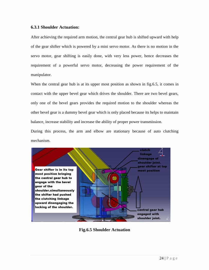
6.3.1 Shoulder Actuation:
After achieving the required arm motion, the central gear hub is shifted upward with help
of the gear shifter which is powered by a mini servo motor. As there is no motion in the
servo motor, gear shifting is easily done, with very less power, hence decreases the
requirement of a powerful servo motor, decreasing the power requirement of the
manipulator.
When the central gear hub is at its upper most position as shown in fig.6.5, it comes in
contact with the upper bevel gear which drives the shoulder. There are two bevel gears,
only one of the bevel gears provides the required motion to the shoulder whereas the
other bevel gear is a dummy bevel gear which is only placed because its helps to maintain
balance, increase stability and increase the ability of proper power transmission.
During this process, the arm and elbow are stationary because of auto clutching
mechanism.
Fig.6.5 Shoulder Actuation
25 | P a g e
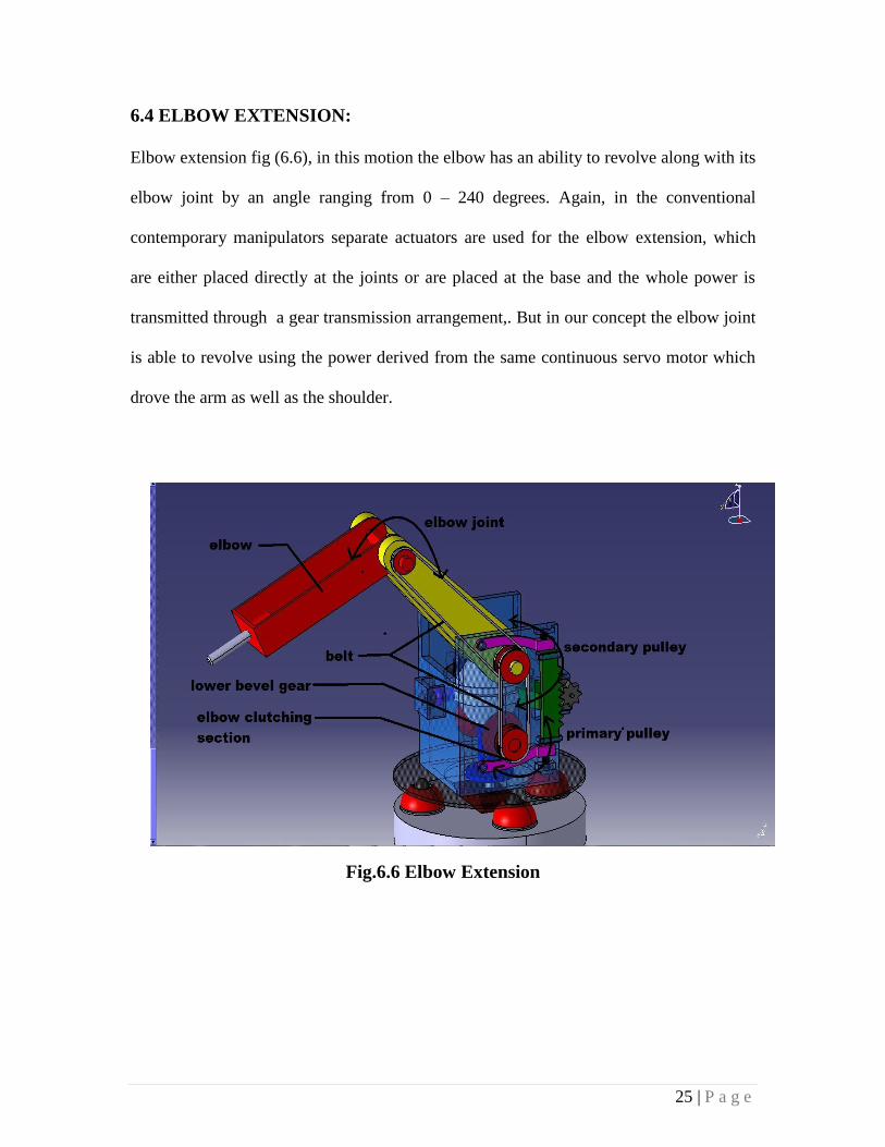
6.4 ELBOW EXTENSION:
Elbow extension fig (6.6), in this motion the elbow has an ability to revolve along with its
elbow joint by an angle ranging from 0 – 240 degrees. Again, in the conventional
contemporary manipulators separate actuators are used for the elbow extension, which
are either placed directly at the joints or are placed at the base and the whole power is
transmitted through a gear transmission arrangement,. But in our concept the elbow joint
is able to revolve using the power derived from the same continuous servo motor which
drove the arm as well as the shoulder.
Fig.6.6 Elbow Extension
26 | P a g e
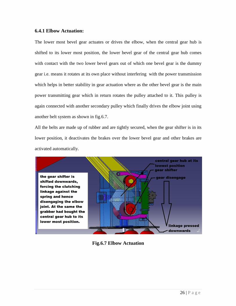
6.4.1 Elbow Actuation:
The lower most bevel gear actuates or drives the elbow, when the central gear hub is
shifted to its lower most position, the lower bevel gear of the central gear hub comes
with contact with the two lower bevel gears out of which one bevel gear is the dummy
gear i.e. means it rotates at its own place without interfering with the power transmission
which helps in better stability in gear actuation where as the other bevel gear is the main
power transmitting gear which in return rotates the pulley attached to it. This pulley is
again connected with another secondary pulley which finally drives the elbow joint using
another belt system as shown in fig.6.7.
All the belts are made up of rubber and are tightly secured, when the gear shifter is in its
lower position, it deactivates the brakes over the lower bevel gear and other brakes are
activated automatically.
Fig.6.7 Elbow Actuation
27 | P a g e
6.5 ARM ACTUATION AND AUTO CLUTCHING CONCEPT:
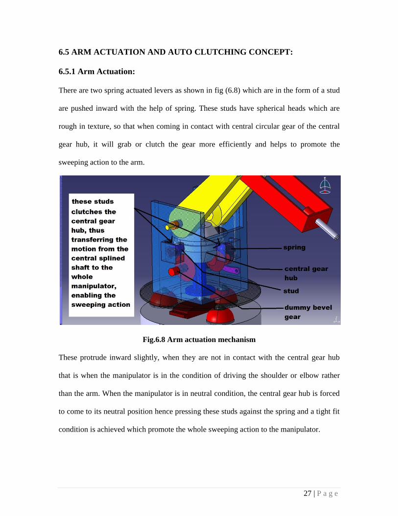
6.5.1 Arm Actuation:
There are two spring actuated levers as shown in fig (6.8) which are in the form of a stud
are pushed inward with the help of spring. These studs have spherical heads which are
rough in texture, so that when coming in contact with central circular gear of the central
gear hub, it will grab or clutch the gear more efficiently and helps to promote the
sweeping action to the arm.
Fig.6.8 Arm actuation mechanism
These protrude inward slightly, when they are not in contact with the central gear hub
that is when the manipulator is in the condition of driving the shoulder or elbow rather
than the arm. When the manipulator is in neutral condition, the central gear hub is forced
to come to its neutral position hence pressing these studs against the spring and a tight fit
condition is achieved which promote the whole sweeping action to the manipulator.
28 | P a g e
6.5.2 Auto Clutching:
As the driving of the three joints is been explained in the previous sub-sections another
problem arises when we have to keep the shoulder and elbow at the desired position to
accomplish the required job.
Hence, in contemporary manipulator if, it is a serial type manipulator clutches are used,
so as the joints are activated only when they are driven and are locked at their positions
when are not actuated. These clutches are generally of electromagnetic types, that means
these clutches acts due to an electromagnetic field been created which forces the stopper
stopping the linkages like the shoulder and the elbow at their position. These
electromagnetic are very expensive and if these are to be custom made for a particular
size robot, then it will cost even more, hence increasing the all total cost of the
manipulator.
Eliminating this use of an electromagnetic clutch, a concept is proposed in this design,
which consists of a spur gear, a linkage with tooth on one side which matches with the
tooth of the spur gear and a helical spring.
The whole arrangement is shown in fig.6.9 when the joint is not in use for the motion of
the joint, the linkage is formed upon the spur gear because of the helical spring as the
linkage can’t move in the direction of the spur gear, it opposes the motion of the spur
gear hence restricting the motion of the linkage.
When the rack type gear shifter shifts the gear to its desired position, at the same time this
desired position at the same time this rack pushes the linkage against the spring just at the
right moment when the bevels are engaged in the drive train.
29 | P a g e
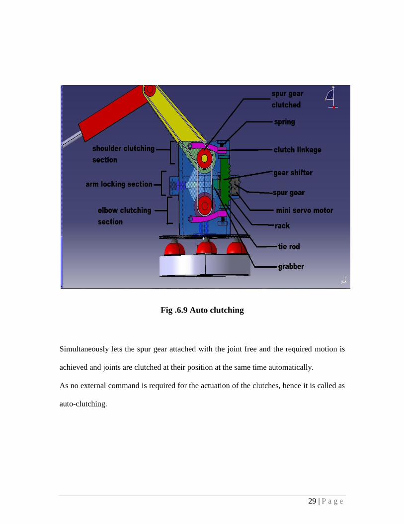
Fig .6.9 Auto clutching
Simultaneously lets the spur gear attached with the joint free and the required motion is
achieved and joints are clutched at their position at the same time automatically.
As no external command is required for the actuation of the clutches, hence it is called as
auto-clutching.
30 | P a g e
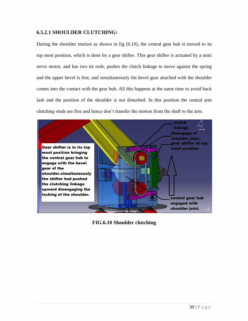
6.5.2.1 SHOULDER CLUTCHING:
During the shoulder motion as shown in fig (6.10), the central gear hub is moved to its
top most position, which is done by a gear shifter. This gear shifter is actuated by a mini
servo motor, and has two tie rods, pushes the clutch linkage to move against the spring
and the upper bevel is free, and simultaneously the bevel gear attached with the shoulder
comes into the contact with the gear hub. All this happens at the same time to avoid back
lash and the position of the shoulder is not disturbed. In this position the central arm
clutching studs are free and hence don’t transfer the motion from the shaft to the arm.
FIG.6.10 Shoulder clutching
31 | P a g e
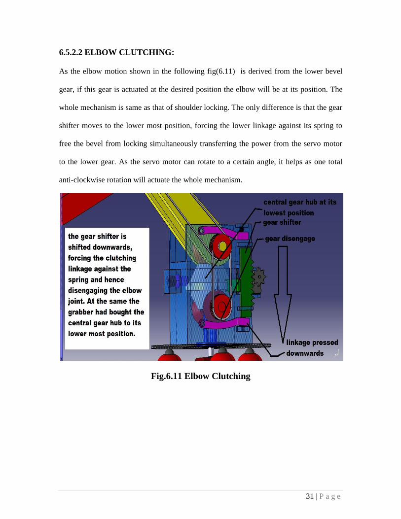
6.5.2.2 ELBOW CLUTCHING:
As the elbow motion shown in the following fig(6.11) is derived from the lower bevel
gear, if this gear is actuated at the desired position the elbow will be at its position. The
whole mechanism is same as that of shoulder locking. The only difference is that the gear
shifter moves to the lower most position, forcing the lower linkage against its spring to
free the bevel from locking simultaneously transferring the power from the servo motor
to the lower gear. As the servo motor can rotate to a certain angle, it helps as one total
anti-clockwise rotation will actuate the whole mechanism.
Fig.6.11 Elbow Clutching
32 | P a g e
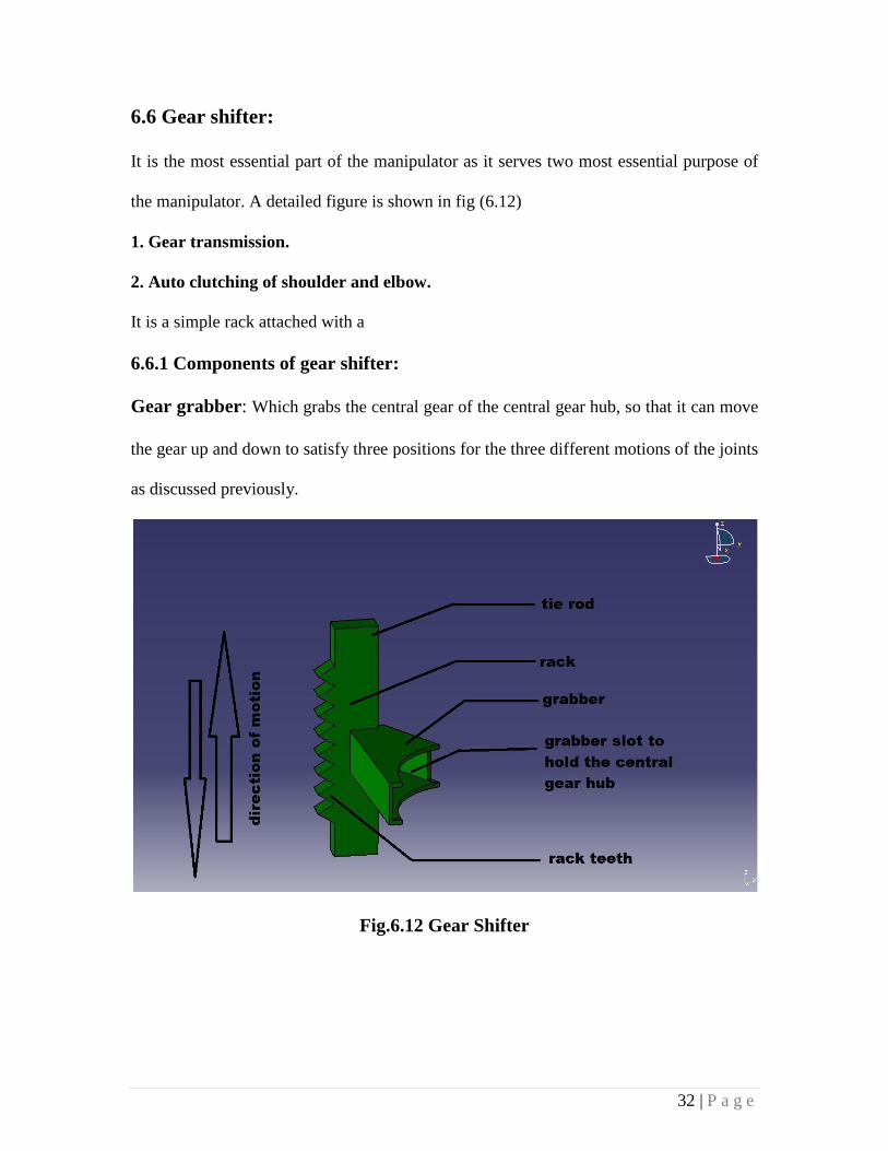
6.6 Gear shifter:
It is the most essential part of the manipulator as it serves two most essential purpose of
the manipulator. A detailed figure is shown in fig (6.12)
1. Gear transmission.
2. Auto clutching of shoulder and elbow.
It is a simple rack attached with a
6.6.1 Components of gear shifter:
Gear grabber: Which grabs the central gear of the central gear hub, so that it can move
the gear up and down to satisfy three positions for the three different motions of the joints
as discussed previously.
Fig.6.12 Gear Shifter
33 | P a g e
The rack: this rack provides with a prismatic motion due to the spur gear messed with it
which is driven by a mini-servo motor as shown.
Tie rod: these tie rod are connected with the rack, which are precisely dimensioned so
as there is no back lash in gear shifting and smooth gear shifting and auto-clutching is
achieved at the same time.
34 | P a g e
CHAPTER 7
CONCLUSION
In this paper the sole aim was to design and develop an idea for an efficient concentric
driven serial chain manipulator and hence a model is been developed over the CATIA V5
R21 software based on completely new idea or concept.
The fundamental idea was to drive all the joints from a single servo motor with the help
of gear transmission where it has 3 positions or we may say three geared position, for
each joint which is shifted mechanically using a special kind of gear shifter which also
helps in the clutching process of the joints so as to keep the whole system in position
when not in use or in motion. Using such mechanical drives it is possible to construct a
concentric driven serial chain manipulator which solely works on a single motor with a
new clutching mechanism that can match the speed and performance of the contemporary
conventional robots, at the same saving us a lot of capital investment over robots.
Apart from this a lot of scope is still there when it comes to manipulators, like the gear
train can be improved and we can eliminate the use of the mini servo as proposed in this
paper with a electromagnetic valve which will actuate the spur gear which in return will
move the rack to achieve the required the clutching and gear shifting actions.
So improvement and optimization is limitless when comes to any subject even if it is a
robotic manipulator which would have its own pros and cons.
35 | P a g e
REFERENCES
1. Eftychios G. Christoforou, Nikolaos V. Tsekos, Robotic manipulators with
remotely–actuated joints:Implementation using drive–shafts and u–joints,
Proceedings of the 2006 IEEE International Conference on Robotics and
Automation Orlando, Florida - May 2006
2. Khurmi & Gupta ,Kinematics & Dynamics of machinery , S Chand.
3. Mark W. Spong, M . Vidyasagar. Robot Dynamics & control, Mc GrawHill
4. Dev satya ranjan , Industrial robotics-technology, programming and applications,
Robotics technology and flexible automation.
5. Sarkar, Xiaoping Yun, and Vijay Kumar,Control of a Single Robot in a
Decentralized Multi-Robot System, Nilanjan General Robotics and Active
Sensory Perception (GRASP) Laboratory.
6. Gupta K C, Kinematic solution of robot with continuous three roll wrists using
zero reference method, 1987.
7. Deb S R , Robotics and flexible automation
8. R.Cohen, M. Lipton, M. Dai and B. Benhabib, Conceptual design of a modular
robot.
9. Groover M P, Industrial robot by, McGrawHill.
10. G.R. slemon, electric machines and Drives, Addison-Wesley(1992)
11. G.R.Slemon and A. Straughen, Electric machines., Addison-Wesley(1980)
12. C. Paredis, H. Brown, R. Casciola, J.Moody, P. Khosla. A rapidly deploable
manipulator system, in : Internation Workshop on Some critical Issues in
Robotics, Singapore, 1995,pp. 175-185

36 | P a g e
13. K. Wurst, The conception and construction of a modular robot system, in
:International Symposium on industrial robotics,pp.37-44.
14. Y. Ishii, T. Fukuzwa, Y.Ichikawa, M. Suzuki, S. Naito and N. Iwatsuka, A joint
connection mechanism and control system for a reconfigurable manipulator.
SICE’92(1992), pp 1095-1098.
15. H.Karbsi, Uni-Drive modular robots. PhD thesis, Department of Mechanical
Engineering, University of Waterloo
16. S Choi and D.W. Cho, Control of wheel slip ratio using sliding mode controller
with pulse width modulation.
17. Stirling Plaatz,Anatomy of robot, Barr and Paatz Industries.