Embed Size (px)
Citation preview

Design and Development of a
Communication-Assisted Microgrid
Protection System
Taha Selim USTUN
B.Sc. and M.Sc. in Electrical and Electronics Engineering
Submitted in fulfillment of the requirements of the degree of
Doctor of Philosophy
School of Engineering and Science, Faculty of Health,
Engineering and Science, Victoria University
2013

Abstract
i
Abstract
Climate change concerns due to the rising amounts of the carbon gas in the atmosphere have
in the last decade or so initiated a fast pace of technological advances in the renewable
energy industry. Such developments in technology and the move towards cleaner sources
of energy have made renewable resources based Distributed Generators (DGs) more
desirable. However, it is a known fact that rising penetrations of DGs have adverse impacts
on the grid structure and its operation. The microgrid concept is a solution proposed to
control the impact of DGs and make conventional grids more suitable for large scale
deployments of DGs.
Unlike conventional utility grids, microgrids comprise generators, storage devices and loads
at all levels of the system. Therefore, power generation, distribution and consumption levels
are not discrete in microgrids and power flows may occur in any direction. Microgrids may
be disconnected from the utility grid and continue its operation under islanding conditions.
Furthermore, some microgrids may have changing structures with alternative paths and the
coupling point for a device or a part of the microgrid may change due to the altering
conditions. Due to their unprecedented structure, these smaller grids experience very
significant protection issues. Conventional fault current protection schemes cannot be used
and should be modified due to the existence of generators at all levels of the distribution
system. It is a challenge to include different types of DG in protection considerations and

Abstract
ii
estimate their fault current contributions. Some DGs, such as Inverter Interfaced DGs
(IIDGs), do not provide high fault currents which makes the fault detection more difficult. On
the other hand, the operating point of relays cannot be lowered boundlessly as this will trigger
erroneous trippings when there is no fault.
In order to sustain a safe operation in such a versatile and dynamic structure, which has
numerous parameters and variables, a new communication-assisted protection strategy is
required. The need of extensive communication between the microgrid components is widely
accepted in the Power Engineering field. In this research, a novel microgrid protection system
has been developed, which utilizes extensive communication to monitor the microgrid and
update relay fault currents according to the variations in the microgrid. This system is
designed to respond to dynamic changes in the microgrid such as connection/disconnection of
DGs. The operating points and connections of microgrid components are analyzed by the
Microgrid Central Protection Unit (MCPU). MCPU implements the protection parameter
calculation and assignment method developed in this work. After performing necessary
calculations, MCPU determines the operating points and updates them into relay settings to
ensure safe and reliable operation.
In this research, the communication infrastructure has been based on international standard
IEC 61850 and its recent extension for DGs, IEC 61850-7-420. New extensions have also
been proposed for these standards where there is a need for a new component such as fault
current limiters or electric vehicles. Since standard logical nodes and communication
procedures are utilized, the developed protection system can easily be installed in new
microgrid, integrated with existing infrastructures and adjusted to new deployments. Given
that the components follow standard communication modeling set by logical nodes defined in

Abstract
iii
IEC 61850 and IEC 61850-7-420, the realization of plug-and-play concept would be easier.
However, it is worthy to highlight that the proposed protection system does not depend on
any particular communication standard or modeling. Should there be the need to use other
standards such as DNP3; this microgrid protection system can be implemented with them as
well.
In order to minimize human input and realize automated process, the microgrid has been
modeled according to the graph theory where the components are represented as nodes.
Dijkstra‟s algorithm, which is famous for shortest-path calculation purposes, is run over the
microgrid to determine the relay hierarchy at any point in time. In this manner, regardless of
the dynamic changes occurring in the microgrid, the hierarchy of network components can be
extracted. The implemented algorithm not only ensures proper selective operation under fault
conditions but also facilitates the introduction of new connections and new devices to the
system. Since the microgrid hierarchy can be detected automatically, even with new
connections, the developed algorithm serves for plug-and-play concepts in electrical
networks.
The main contribution to knowledge presented in this thesis is the development of a new
communication-assisted protection scheme for the protection of microgrids. The developed
protection system is very versatile and can be implemented as the primary protection scheme
in a microgrid, or it can be utilized simultaneously with other protection schemes, or it can be
installed as a roll-back strategy for other protection schemes when they cannot operate due to
a malfunction, e.g. in case of communication or synchronization failures in differential
protection systems.

iv
Declaration of Originality
“I, Taha Selim USTUN, declare that the PhD thesis entitled “Design and Development of a
Communication-Assisted Microgrid Protection System” is no more than 100,000 words in
length including quotes and exclusive of tables, figures, appendices, bibliography, references
and footnotes. This thesis contains no material that has been submitted previously, in whole
or in part, for the award of any other academic degree or diploma. Except where otherwise
indicated, this thesis is my own work”.
Signature Date:
03/07/2013

v
Acknowledgements
In the name of Allah, the Beneficent, the Merciful.
Read in the name of your Lord Who created. He created man from a clot. Who taught (to write) with the pen, Taught man what he knew not.
(The Clot – 96th Surah – Verses 1 to 5)
They said: Glory be to Thee! We have no knowledge but that which Thou hast taught us; surely Thou art the Knowing, the Wise.
(The Cow – 2nd Surah – 32nd Verse)
…and say: O my Lord! Increase me in knowledge.
(Ta Ha – 20th Surah – 114th Verse)
English translations from the original Arabic script, by M.H. SHAKIR.

List of Publications
vi
List of Publications
Peer-Reviewed Journal Papers
[1] Taha Selim Ustun, Cagil Ozansoy, Aladin Zayegh, "Recent developments in microgrids
and example cases around the world--A review," in Renewable and Sustainable Energy
Reviews, Elsevier, vol. 15, pp. 4030-4041, 2011
[2] Taha Selim Ustun, Cagil Ozansoy, Aladin Zayegh, "Modeling of a Centralized Microgrid
Protection System and Distributed Energy Resources According to IEC 61850-7-420," in
IEEE Transactions on Power Systems, vol. PP, pp. 1-8, 2012.
[3] Taha Selim Ustun, Cagil Ozansoy, Aladin Zayegh, "Fault Current Coefficient and Time
Delay Assignment for Microgrid Protection System with Central Protection Unit," in IEEE
Transactions on Power Systems, vol. PP, pp. 2012 .
[4] Taha Selim Ustun, Cagil Ozansoy, Aladin Zayegh, "Implementing Vehicle-to-Grid (V2G)
Technology with IEC 61850-7-420," IEEE Transactions on Smartgrids, vol. PP, pp. 2012
(accepted).
Refereed Conference Papers
[1] Taha Selim Ustun, Cagil Ozansoy, Aladin Zayegh, "A central microgrid protection
system for networks with fault current limiters," in Proceedings of Environment and
Electrical Engineering (EEEIC), 2011 10th International Conference on , vol., no., pp.1-4, 8-
11 May 2011, Rome, Italy, ISBN 978-1-4244-8781-3.
[2] Taha Selim Ustun, Cagil Ozansoy, Aladin Zayegh, "A microgrid protection system with
central protection unit and extensive communication," in Proceedings of Environment and
Electrical Engineering (EEEIC), 2011 10th International Conference on , vol., no., pp.1-4, 8-
11 May 2011, Rome, Italy, ISBN 978-1-4244-8781-3
[3] Taha Selim Ustun, Cagil Ozansoy, Aladin Zayegh, "Distributed Energy Resources (DER)
Object Modeling with IEC 61850-7-420," in Proceedings of Australasian Universities Power
Engineering Conference, AUPEC, 2011.
[4] Taha Selim Ustun, Cagil Ozansoy, Aladin Zayegh, "Implementation of Dijkstra‟s
Algorithm in a Dynamic Microgrid for Relay Hierarchy Detection," in Proceedings of Second
IEEE International Conference on Smart Grid Communications (SmartGridComm), Belgium,
2011.
[5] Taha Selim Ustun, Cagil Ozansoy, and Aladin Zayegh; “Extending IEC 61850-7-420 for
Distributed Generators with Fault Current Limiters”; in Proceedings of Innovative Smart
Grid Technologies Conference ASIA (ISGT Asia), 2011 IEEE PES , Perth, Australia, 13-17
Nov., 2011

List of Publications
vii
[6] Taha Selim Ustun, Cagil Ozansoy, and Aladin Zayegh; "Using Object Oriented Data
Structures for Dynamic Communication and Control in Electrical Networks"; in Proceedings
of 25th Canadian Conference on Electrical and Computer Engineering (CCECE), 2012, April
29-2 May 2012
[7] Taha Selim Ustun, Cagil Ozansoy, and Aladin Zayegh; "Electric Vehicle Potential of
Australian Households Based On Vehicle Ownership and Usage"; in Proceedings of 25th
Canadian Conference on Electrical and Computer Engineering (CCECE), 2012, April 29-2
May 2012
[8] Jarred Wentzel, Taha Selim Ustun, Cagil Ozansoy, and Aladin Zayegh; “Investigation of
Micro-Grid Behavior While Operating Under Various Network Conditions"; in Proceedings
of IEEE International Conference on Smart Grid Engineering (SGE‟12) 27-29 August, 2012
UOIT, Oshawa, Canada
[9] Taha Selim Ustun, Cagil Ozansoy, and Aladin Zayegh, " Simulation of Communication
Infrastructure of a Centralized Microgrid Protection System Based on IEC 61850-7-420," in
Proceedings of Third IEEE International Conference on Smart Grid Communications
(SmartGridComm), Tainan City, Taiwan, November 2012
Under Review:
[1] Taha Selim Ustun, Cagil Ozansoy, Aladin Zayegh, "Modeling Electrical Networks with
Object Oriented Data Structures for Smart Control," International Journal of Electrical Power
and Energy Systems, Elsevier
[2] Taha Selim Ustun, Cagil Ozansoy, Aladin Zayegh, "Investigation of Electric Vehicle
Potential of Australian Households and Its Impact on Smartgrids," IEEE Industrial
Electronics Magazine, Special Issue on Microgrids
[3] Taha Selim Ustun, Cagil Ozansoy, Aladin Zayegh, "Differential Protection of Microgrids
with Central Protection Unit Support”, IEEE PES Conference on Innovative Smart Grid
Technologies, Sao Paulo, Brazil, ISGT-LA 2013, 15 – 17 April, 2013
[4] Taha Selim Ustun, Cagil Ozansoy, Aladin Zayegh, "Modeling and Simulation of a
Microgrid Protection System with Central Protection Unit," ECCE Asia DownUnder 2013, 3-
6 June 2013, Crown Conference Center, Melbourne, Australia

viii
Table of Contents
Abstract ...................................................................................................................................... i
Declaration of Originality ......................................................................................................... iv
Acknowledgements .................................................................................................................... v
List of Publications ................................................................................................................... vi
Table of Contents ................................................................................................................... viii
List of Figures ........................................................................................................................ xiii
List of Tables ....................................................................................................................... xviii
List of Abbreviations ............................................................................................................... xx
Chapter 1 .................................................................................................................................. 1
Thesis Overview ....................................................................................................................... 1
1.1. Introduction ................................................................................................................ 1
1.2. Aim of This Research ................................................................................................. 2
1.3. Research Methodologies and Techniques ................................................................. 8
1.4. Originality of the Thesis ........................................................................................... 11
1.5. Organization of the Thesis ....................................................................................... 13
Chapter 2 ................................................................................................................................ 16
Literature Review on Microgrid Concept and Its Implementation .................................. 16
2.1. Introduction .............................................................................................................. 16
2.2. The Microgrid Concept ............................................................................................ 19
2.3. Current Status of Literature and Ongoing Research ............................................. 21
2.3.1. Control ............................................................................................................... 23
2.3.2. Protection ........................................................................................................... 28
2.3.2.1. Islanding Detection .......................................................................................... 28
2.3.2.2. Fault Current Protection .................................................................................. 31

ix
2.3.3. Microgrid Energy Management System (MEMS) .............................................. 38
2.4. Examples around the World .................................................................................... 42
2.4.1. European Union (EU) ........................................................................................ 42
2.4.2. Japan .................................................................................................................. 43
2.4.3. Korea.................................................................................................................. 44
2.4.4. North America .................................................................................................... 45
2.4.5. Australia ............................................................................................................. 46
2.5. Standards and Universalization ............................................................................... 47
2.6. Impact of Electric Vehicles (EVs) on Future Microgrids ...................................... 51
2.7. Conclusion ................................................................................................................ 53
Chapter 3 ................................................................................................................................ 56
Conceptual Design of Centralized Microgrid Protection System ...................................... 56
3.1. Introduction ............................................................................................................... 56
3.2. Fault Current Challenges in Microgrids .................................................................. 58
3.3. Microgrid Protection System with Central Protection Unit and Extensive
Communication .................................................................................................................... 67
3.4. Power Networks with Fault Current Limiters(FCL) ................................................. 74
3.5. Conceptual Design with Fault Current Limiter ........................................................ 77
3.6. Conclusion ................................................................................................................. 81
Chapter 4 ................................................................................................................................ 83
Object Oriented Modeling of Microgrids and Automated Structure Detection .............. 83
4.1. Introduction .............................................................................................................. 83
4.2. Object Oriented (OO) Representation of Power Networks ..................................... 86
4.3. Relay Hierarchy and Selectivity Issues.................................................................... 93
4.4. Dijkstra’s Algorithm for Automated Structure Detection....................................... 98
4.5. Plug-and-play for new deployments ...................................................................... 106

x
4.6. Conclusion .............................................................................................................. 108
Chapter 5 .............................................................................................................................. 110
Fault Current and Time Delay Assignment for Relays .................................................... 110
5.1. Introduction ............................................................................................................ 110
5.2. Calculation of Grid Fault Current Contribution .................................................. 111
5.3. Calculation of DG impact factor – k ..................................................................... 114
5.4. Relay Hierarchy adjustment for selectivity ........................................................... 118
5.5. Faults outside the microgrid .................................................................................. 124
5.6. Reliability considerations ....................................................................................... 127
5.7. Conclusion .............................................................................................................. 129
Chapter 6 .............................................................................................................................. 131
IEC 61850-Based Modeling of the Microgrid Protection System .................................. 131
6.1. Introduction ............................................................................................................ 131
6.2. IEC 61850 International Standard ........................................................................ 132
6.3. Modeling DER Systems with IEC 61850-7-420 Extension .................................. 136
6.3.1. DER Unit Controller ....................................................................................... 138
6.3.2. Internal Parameters ........................................................................................ 139
6.3.3. Grid Connection Units .................................................................................... 140
6.3.4. Network Operator Units .................................................................................. 141
6.4. Extending IEC 61850-7-420 for New Grid Components ...................................... 141
6.4.1. Fault Current Limiter Extension for IEC 61850-7-420 ................................ 142
6.4.1.1. Updating the DER controller LN (DRCT) ..................................................... 143
6.4.1.2. Information Modeling for the FCL Logical Device ....................................... 144
6.4.2. Electric Vehicle (EV) Extension..................................................................... 147
6.4.2.1. Current Status of EV Technologies ............................................................... 148
6.4.2.2. Modeling EVs with IEC 61850-7-420 for communication in Smartgrids ..... 153

xi
6.5. MCPU Modeling with IEC 61850-7-420 ............................................................... 158
6.6. Data Maps With IEC 61850-7-420 Models ........................................................... 166
6.7. Conclusion .............................................................................................................. 171
Chapter 7 .............................................................................................................................. 174
Microgrid Operation and Protection Simulations ............................................................ 174
7.1. Introduction ............................................................................................................ 174
7.2. Microgrid Operation Simulations .......................................................................... 176
7.2.1. Microgrid Simulation - Islanded Operation .................................................... 179
7.2.2. Grid-Connected Simulation: Transmission Network Connection, IEEE T14-Bus
System 180
7.2.3. Grid-Connected Simulation: Distribution Network Connection, IEEE 34-Bus
System 184
7.2.4. Microgrid V2G-G2V Simulations for EV (Charging/Supplying)..................... 187
7.3. Fault Parameter follow-up for Microgrid Operation Simulations ....................... 189
7.3.1. MATLAB Simulation Results............................................................................ 194
7.4. Communication Interface Simulations ................................................................. 198
7.4.1. Simulation Works and Resultant Data Maps ................................................... 202
7.5. Conclusion .............................................................................................................. 207
Chapter 8 .............................................................................................................................. 209
Operation of the Proposed Protection System under Different Protection Scenarios .. 209
8.1. Introduction ............................................................................................................ 209
8.2. Operation with Other Microgrid Protection Systems ............................................ 211
8.3. Usage of Proposed System as a support for Differential Protection .................... 216
8.3.1. Differential Protection with Microgrid Central Protection Unit (MCPU) ....... 221
8.3.2. Communication Infrastructure Reliability Considerations ............................... 227
8.4. Conclusions ............................................................................................................ 230

xii
Chapter 9 .............................................................................................................................. 232
Conclusions and Future Work ............................................................................................ 232
9.1. Introduction ........................................................................................................... 232
9.2. Key Contributions of the Research ........................................................................ 234
9.3. Future Work ........................................................................................................... 238
References .............................................................................................................................. 240
Appendix – A IEEE 14 Bus Test System .............................................................................. 252
Appendix – B IEEE 34 Bus Test System............................................................................... 254
Appendix – C Short Circuit Analysis Results for Simulated Power Systems ....................... 256
Appendix – D IEC 61850-7-420 Modeling Details for Various DERs ................................. 265

xiii
List of Figures
Figure 2.1. A Sample Microgrid Architecture ................................................................... 20
Figure 2.2. Different droop lines and operating points in [45] .......................................... 27
Figure 2.3. Grid and DG fault current contribution in MG ................................................ 32
Figure 2.5 Adaptive Microgrid Protection System proposed in [73] .................................. 35
Figure 2.6 Implementation of Selectivity with interlock direction in [73] ......................... 36
Figure 2.7. Control Levels of the Microgrid [100] ............................................................ 39
Figure 2.8. CERTS Microgrid [6] ....................................................................................... 46
Figure 2.9. IEEE SCC21 1547 Series of Interconnection Standards [61] .......................... 48
Figure 3.1. Grid connected-Mode, Internal Three-phase Fault ........................................... 60
Figure 3.2. Islanded Mode – Internal Three-phase Fault .................................................... 61
Figure 3.3. Nuisance Tripping ............................................................................................ 62
Figure 3.4. Selectivity Issue ................................................................................................ 64
Figure 3.5. Reverse Selectivity for Faults outside the Microgrid ....................................... 66
Figure 3.6. Topology of the Developed Microgrid Protection System ............................... 67
Figure 3.7. Interrupt-based Protection Algorithm ............................................................... 73
Figure 3.8. Solid state FCL topology in [158]. ................................................................... 75
Figure 3.9. The inverter interface used in [157]. ................................................................. 76
Figure 3.10. Fault current limitation algorithm for the topology in Figure 3.9 [157]. ........ 76
Figure 3.11. Fault current limitation curves for inverter topology [160]. ........................... 77
Figure 3.12. Protection Algorithm employed in MCPU for FCLs. .................................... 80
Figure 4.2. Abstraction of NS for different Node types handled by Update Settings
Function ............................................................................................................................... 89
Figure 4.3. Bus bar Locations in a Sample Microgrid where Dummy Node is required .... 91
Figure 4.4. A section of a network with various nodes ....................................................... 91

xiv
Figure 4.5. Topology After Connect (Relay X) Service ..................................................... 92
Figure 4.6. A sample microgrid .......................................................................................... 94
Figure 4.7. The network structure when CB5 is open and CB4 is closed (1st Case) .......... 95
Figure 4.8.The Network structure when CB5 closes and CB4 opens (2nd
Case) ................ 95
Figure 4.9. A sample graph for shortest path problem ........................................................ 98
Figure 4.10. 1st Loop, First 3-steps performed on „node a‟ ................................................. 99
Figure 4.11. 2nd
Loop, First 3-steps performed on „node d‟ ............................................. 100
Figure 4.12. 3rd
Loop, First 3-steps performed for node b ................................................ 100
Figure 4.13. Modeling of microgrid in Case 1 according to graph theory ........................ 102
Figure 4.14. Modeling of microgrid in Case 2 according to graph theory ........................ 102
Figure 4.15. Dijkstra‟s Algorithm run for case 1, Path from CB2 to DG4 ....................... 104
Figure 4.16. Dijkstra‟s Algorithm run for case 2, after grid re-configuration, Path from
CB2 to DG4 ....................................................................................................................... 105
Figure 4.17. Dijkstra‟s Algorithm run after new deployments, Path from CB2 to DG6 .. 106
Figure 5.1. Thevenin Equivalent Circuit taken from Point A ........................................... 112
Figure 5.2. Fault Contribution of DG at different locations ............................................. 114
Figure 5.3. Symmetrical components scheme ................................................................... 115
Figure 5.4. A sample microgrid ........................................................................................ 119
Figure 5.5. 2-pair Selectivity Method Algorithm .............................................................. 120
Figure 5.6. The network structure change from Case 1 (a) to Case 3 (b) ......................... 123
Figure 5.7. Faults in the Utility Grid ................................................................................. 125
Figure 5.8. Local Decision Making scheme in Relays ...................................................... 128
Figure 6.1. Generic DER system in IEC 61850-7-420 [197] ............................................ 136
Figure 6.2. Fault current limitation for inverter topology [160]. ...................................... 143
Figure 6.3. Virtualization of Fault Current Limiters with proposed LNs ......................... 145

xv
Figure 6.4. FACL Class in Generic DER system (IEC 61850-7-420) .............................. 147
Figure 6.5. A HEV with a series hybrid power train ........................................................ 149
Figure 6.6. A HEV with a parallel hybrid power train ...................................................... 149
Figure 6.7. A PHEV with a series-parallel hybrid power train ......................................... 150
Figure 6.8. Charging time of Several Vehicles for Different Charging Options .............. 152
Figure 6.9. Modeling EVs with IEC 61850-7-420. ........................................................... 155
Figure 6.10. Virtualization of Electric Vehicles with proposed LNs ................................ 157
Figure 6.11. EVCT Class in Generic DER system (IEC 61850-7-420) ............................ 157
Figure 6.12. Relay LD incorporating various functions modeled with LNs ..................... 159
Figure 6.13. Reciprocating Engine Information Model .................................................... 160
Figure 6.14. Fuel Cell Modeling ....................................................................................... 162
Figure 6.15. PV Panel Modeling ....................................................................................... 165
Figure 6.16. The system modeled according to IEC 61850-7-420 ................................... 166
Figure 6.17. Reporting DG status through IEC 61850-7-420 Models .............................. 168
Figure 6.18. Reporting Relay status through IEC 61850-7-420 Models .......................... 169
Figure 6.19. Updating Relay operating Currents through IEC 61850-7-420 Models ....... 171
Figure 7.1. Micro-grid network structure used for investigation & simulation ............... 176
– when bus 4 is connected to bus 3 through CB5 ............................................................. 176
Figure 7.2. Micro-grid network structure used for investigation & simulation ............... 177
– when bus 4 is connected to bus 2 through CB12 ........................................................... 177
Figure 7.3. IEEE Standard T14 Bus System [212] with Microgrid Connection .............. 182
Figure 7.4. IEEE Standard 34 Bus System [213] with Microgrid Connection ................. 185
Figure 7.5. The Sample Microgrid with EV deployments (G2V mode – charging) ......... 187
Figure 7.6. The Sample Microgrid with EVs operating in V2G mode ............................. 188
Figure 7.7. Relay model with Communication Module .................................................... 190

xvi
Figure 7.8. Relay Communication and Control Module ................................................... 190
Figure 7.9. DG with Communication Module .................................................................. 192
Figure 7.10. MCPU Block (inside) ................................................................................... 193
Figure 7.11. The Microgrid Model Simulated in MATLAB/Simulink ............................ 195
Figure 7.12. Current Waveforms for the Grid and DG1 ................................................... 196
Figure 7.13. Current Waveforms for DG2 and DG3......................................................... 197
Figure 7.14. Operating Mode Signal and Tripping Current .............................................. 197
Figure 7.15. Total Current flow in the Network ............................................................... 198
Figure 7.16. Relay Block with XCBR, PTOC and TCTR LNs ........................................ 199
Figure 7.17. DG model with DRCT and DRCS LNs ........................................................ 200
Figure 7.18. StatusDG module (in MCPU) to extract connection status of DGs ............... 201
Figure 7.19. IfaultDG module (in MCPU) to extract fault contribution of DGs .............. 202
Figure 7.20. The system for which communication modeling is performed .................... 202
Figure 7.21. MCPU operating with modeled Relay and DG blocks ................................. 205
Figure 7.22. The Communication Infrastructure modeled according to IEC 61850-7-420
........................................................................................................................................... 206
Figure 8.1. Interaction of the Proposed Protection System with Others ........................... 212
Figure 8.2. Status of the network after inclusion of CB1 and CB2 in the Proposed
Protection System .............................................................................................................. 214
Figure 8.3. A sample differential protection topology ..................................................... 217
Figure 8.4. Differential Protection for power lines .......................................................... 218
Figure 8.5. A double-slope restraint characteristic [222] .................................................. 218
Figure 8.6. Multi-terminal protection zone with several currents ..................................... 220
Figure 8.7. Topology of the Developed Differential Protection with MCPU ................... 222
Figure 8.8. Local Decision Making without Continuous Communication ...................... 224

xvii
Figure 8.9. Protection Algorithm employed in MCPU. ................................................... 226
Figure 8.10. Fault Probability Distribution in a Multi-Terminal Protection Zone ............ 229

xviii
List of Tables
Table 2.1. Batteries Used For Distributed Energy Storage ................................................. 22
Table 2.2. Control Strategies for DG coupling Inverters in MG ........................................ 24
Table 3.1. Data Maps in the Central Protection Unit .......................................................... 70
Table 3.2. Data Maps in the Central Protection Unit .......................................................... 78
Table 4.1. Details of Relay X ............................................................................................. 92
Table 4.2. Details of Load .................................................................................................. 92
Table 4.3. Details of Relay X After Load.Disconnect (Relay X) ...................................... 93
Table 4.4. Shortest Path from “node a” ............................................................................ 101
Table 4.5. The Path from “Circuit Breaker 2” ................................................................. 105
Table 4.6. The Path from “Circuit Breaker 2” After New Deployments ......................... 107
Table 5.1. 2-pair Selectivity Method Data ........................................................................ 120
Table 5.2. Critical Relay Hierarchy For Various Cases .................................................... 122
Table 5.3. Relay Pairing For Case 1 ................................................................................. 122
Table 5.4. Relay Pairing For Case 3 ................................................................................. 124
Table 5.5. Bidirectional Parameters For Case 1 ................................................................ 126
Table 6.1. Updated DRCT Class ....................................................................................... 144
Table 6.2. FACL Class ...................................................................................................... 146
Table 6.3. Typical Set of EV Charging Options ............................................................... 151
Table 6.4. Battery Characteristics of Different EVs ......................................................... 152
Table 6.5. Updated DRCT Class ....................................................................................... 154
Table 6.6. Proposed EVCT Class ...................................................................................... 156
Table 6.7. Network Component Parameters at t=0 sec ..................................................... 168
Table 6.8. Network Component Parameters at t=0.5 sec .................................................. 169
Table 6.9. Network Component Parameters at t=1.25 sec ................................................ 170
xix
Table 7.1 – Micro-Grid Loading Magnitudes ................................................................... 177
Table 7.2 – Distributed Generation Type & Magnitude of Power Generated .................. 178
Table 7.3 – Islanded Operation: Micro-grid Configuration 1 - Branch Flow Results ...... 180
Table 7.4 – Islanded Operation: Micro-grid Configuration 2 - Branch Flow Results ...... 180
Table 7.5 – Grid Connected Operation: T14 Bus System - Micro-grid Configuration 1 . 183
Power Flow Results ........................................................................................................... 183
Table 7.6 – Grid Connected Operation: T14 Bus System - Micro-grid Configuration 2 . 183
Power Flow Results ........................................................................................................... 183
Table 7.7 – Grid Connected Operation: IEEE Standard 34 Bus System - Micro-grid
Configuration 1 Power Flow Results ................................................................................ 186
Table 7.8 – Grid Connected Operation: IEEE Standard 34 Bus System - Micro-grid
Configuration 2 Power Flow Results ............................................................................... 186
Table 7.9 – Simulation Results for Test Cases ................................................................. 189
Table 7.10 – Network Component Parameters ................................................................. 196
Table 7.11 – Network Component Parameters at t=0 Sec ................................................ 204
Table 7.12 – Network Component Parameters at t=0.5 Sec ............................................. 204
Table 8.1. Data Maps for Operation with Other Protection Systems ................................ 213
Table 8.2. Selectivity Table for Operation with Other Protection Systems ...................... 213
Table 8.3. Data Maps After Integration of CB1 and CB2 ................................................ 215
Table 8.4. 2-pair Selectivity List After New Integrations ................................................. 215
Table 8.5. Multi-terminal Differential Protection Zones ................................................. 223
Table 8.6. Data Maps in the MCPU .................................................................................. 224

xx
List of Abbreviations
AC Alternating Current
ACSI Abstract Communication Service Interface
ASG Analogue Setting
CB Circuit Breaker
CCM Communication and Control Module
CDC Common Data Class
CERTS Consortium for Electric Reliability Technology Solutions
CORBA Common Object Request Broker Architecture
CT Current Transformer
DC Direct Current
DCOM Distributed Component Object Model
DCP Controllable Double Point
DER Distributed Energy Resource
DG Distributed Generator
DMS Distribution Management System
DNO Distribution Network Operator
ECP Electrical Connection Point
EE Electrical Engineering
ENN Electrical Network Node
EV Electric Vehicle
FACTS Flexible AC Transmission System
FCL Fault Current Limiter
FQB Frequency-Reactive Power Boost

xxi
G2V Grid-to-Vehicle
GOOSE Generic Object Oriented Substation Event
GTO Gate Turn Off
HEV Hybrid Electric Vehicle
ICS Internal Combustion Engine
IEC International Electrotechnical Committee
IED Intelligent Electronic Device
IGBT Insulated Gate Bipolar Transistor
IIDG Inverter Interfaced Distributed Generator
ING Integer Status Setting
IR Individual Relay
LC Local Controller
LD Logical Device
LN Logical Node
LV Low Voltage
MCPU Microgrid Central Protection Unit
MEMS Microgrid Energy Management System
MGCC Microgrid Central Controller
MHEPP Micro Hydroelectric Power Plant
MMS Manufacturing Message Specification
MMS Microgrid Management System
MO Market Operator
MPPT Maximum Power Point Tracking
MV Measured Value
MV Medium Voltage
xxii
NS Node Settings
OO Object-Oriented
PE Power Electronics
PHEV Plug-in Hybrid Electric Vehicle
PLC Power Line Carrier
PV Photovoltaic
R&D Research and Development
RBD Reliability Block Diagram
RE Renewable Energy
RoCoF Rate-of-Change-of-Frequency
SAS Substation Automation System
SCADA Supervisory Control and Data Acquisition
SCC21 IEEE Standard Coordinating Committee 21
SCFCL Superconducting Fault Current Limiter
SPS Single Point Status
T&D Transmission and Distribution
TCP/IP Transmission Control Protocol/Internet Protocol
UML Unified Model Language
V2G Vehicle-to-Grid
VPD Voltage-Power Droop
VPP Virtual Power Plant
VSI Voltage Source Inverter

Chapter 1: Thesis Overview
1
Chapter 1
Thesis Overview
1.1. Introduction
The search for cleaner and more efficient power systems drew engineers‟ attention to
Distributed Generators (DGs). As a result of recent developments in technology and concerns
for global warming, the new tendency in the Power Engineering field is to generate electricity
from cleaner energy sources and closer to the consumption areas [1]. This implies that the
share of DG in the power generation shall increase substantially. These generators may be
Renewable Energy (RE) based such as wind turbines and solar systems.
However, existing transmission and distribution networks are not suitable for large scale DG
connections since they were traditionally designed with the assumption of a passive network.
The DG interconnection to such networks changes their fundamental characteristics and
create unprecedented technical problems [2]. Moreover, in the case of a fault, DG systems
contribute to the fault currents and the transient characteristics of the network become
completely different [3]. Since the Inverter Interfaced DGs (IIDGs) have highly variable
characteristics, they alter the grid structure and jeopardize safe and reliable operation[4].
These are only a few of the issues caused by the connection of DGs to grids. In order to

Chapter 1: Thesis Overview
2
overcome these problems a new concept called “microgrid” is proposed by the power
engineers.
A microgrid is a collection of loads and micro-generators along with some local storage and
behaves like a model-citizen [5] from grid side thanks to intelligent control [6]. Although a
microgrid has many generators and loads, it appears as a net load or a net generator to the
broader grid with well-behaved characteristics [7], i.e. with stable voltage and frequency.
Through microgrids, the gigantic conventional utility network can be divided into smaller
networks which manage distributed generators, loads, storage and protection devices in their
own grid [8]. In microgrids, these generators are handled in smaller quantities and, thus, DGs
can be connected to the grid and side-effects on the grid operation can be eliminated.
Despite their advantages, microgrids bring along some technical challenges in control,
management and protection fields [9, 10]. Since the very basics of conventional network
operation do not hold any more (such as grid‟s being radial and passive) revolutionary
changes are required for safe operation. Protection systems, in particular, are affected heavily
by the current contribution of DGs and the bidirectional power flow. Therefore, a new
approach is required for power grid protection purposes.
1.2. Aim of This Research
The research presented in this thesis aimed to investigate the impact of Distributed
Generators (DGs) on the operation of electrical networks and design a novel protection
system with extensive communication. In order to accommodate new deployments and
follow the dynamic changes occurring in a microgrid, the proposed protection system has
been designed to be flexible and versatile. In line with the smartgrid evolution, the proposed

Chapter 1: Thesis Overview
3
protection system uses communication lines to gather information and send data. This
communication infrastructure has been based on and modeled according to the international
substation communication standard IEC 61850 [11] and its extension for DGs, IEC 61850-7-
420[12].
The specific aims of this research can be summarized as follows:
Research on evolving concepts of microgrids and smartgrids
Extensive literature review has been performed to closely follow the recent developments in
microgrid and smartgrid research areas. Being relatively new in power engineering field,
these areas constantly develop at a high speed. It is imperative to monitor the research work
and the associated findings almost on a day-to-day basis to stay up to date with these areas.
The literature review was performed in a wide perspective, so as to include the evolution
power networks are experiencing nowadays. Old, interconnected, passive and massive power
networks are being transformed into smaller and isolated smaller entities which may be both
active and passive. The motivations behind this evolution, its impact on power networks,
practical aspects which relate to the end-users, novel technologies and possible research areas
have been investigated in detail. Accordingly, this research has touched upon various
concepts in the power engineering field such as network protection, fault currents, relay
programming, communication standards, communication infrastructure and new technologies
such as Fault Current Limiters (FCLs) and Electric Vehicles (EVs). The literature review
provided in this research provides a good reference for these different concepts, their places
in microgrids and possible future research work in the field.
Investigation of the impact of DGs on microgrids

Chapter 1: Thesis Overview
4
It is not a secret that recent years have experienced a sharp increase in the network
penetration of DG systems . This can be traced back to benefits of DGs such as lower carbon
emissions, more environment friendly generation, less dependence on oil and its products for
electricity generation as well as local generation and grid-support at peak hours. However,
electricity networks were designed several decades ago. There was no local generation in
those days and the power flow was unidirectional from generation points to consumption
points. The addition of DGs to power networks at various levels such as transmission and
distribution renders these earlier assumptions invalid. The consequences of DG usage have
been investigated thoroughly in this research, especially from fault levels and fault current
protection perspectives. The work carried out was not limited conventional DGs such as
diesel generators or PV panels but novel technologies such as Electric Vehicles (EVs) have
also been studied.
Investigation of the potential and impact of Electric Vehicles (EVs) and Vehicle-to-
Grid (V2G) operation on microgrids
Due to rising oil prices and environmental concerns, EVs have become very popular and car
manufacturers increased their focus on EV technology. Also, governments started giving
incentives for wide spread EV usage. Therefore, this research focused on investigating the
potential of EVs from social and financial perspectives. Some test cases have been set up and
simulated in order to investigate the impacts of EVs on microgrids under Vehicle-to-Grid
(V2G) and Grid-to-Vehicle (G2V) operating conditions when they are supplying power to the
grid and drawing power from the grid, respectively.
Design of a novel communication-assisted protection system
Following the investigations and findings above, a novel protection system which uses
extensive communication has been designed. Communication lines are deemed necessary for

Chapter 1: Thesis Overview
5
the fact that microgrids are not only differ from conventional electrical grids in terms of their
size, hence micro-grid, but also in terms of intelligence, hence the term smartgrid is used.
These new generation grids require the components and the management system to be
smarter, to monitor even the slightest of changes, to communicate with different parts of the
grid and make decisions on the fly. Therefore, the protection system proposed in this thesis
incorporates communication between the components and the central management unit. The
novelty of this research is its special focus on the fault protection in microgrids. In the
literature, there have been several works done in the management, load sharing and
marketing fields but little has been contributed towards the design of a protection system for
the unprecedented conditions occurring in microgrids.
Assignment of protection parameters on the fly
One of the key contributions of this research is the developed ability to calculate the fault
current parameters required to coordinate the protection devices in the protection system. In
conventional power networks, the passive mode of operation and the unidirectional power
flow eased the protection calculations massively. Power Engineers had the luxury to calculate
fault conditions beforehand and program protection devices accordingly. However, the
dynamic nature of microgrids, bidirectional power flows, presence of generation at every
level of power networks require that the protection systems shall follow all these changes and
calculate operating points for any modification, when it occurs. It is almost impossible to
calculate and tabulate all of the possible conditions in a microgrid beforehand. Even if it is
accomplished, a new deployment or a new connection of a generator would require all of the
calculations and possible cases to be updated. Therefore, a calculation method has been
developed where the fault levels and fault current contributions are calculated by the
protection system automatically. In this fashion, human input is lowered to a minimum and
automated operation can be realized.

Chapter 1: Thesis Overview
6
Modeling communication infrastructure with international substation communication
standard IEC 61850 and its extension for DGs, IEC 61850-7-420
In addition to designing a new protection system for microgrids, this research contributes to
the knowledge by modeling the whole system along with its components in compliance with
international substation communication standard IEC 61850 and its recent extension IEC
61850-7-420. This is a solid step towards standardizing the communication required for the
microgrids. It is constantly repeated in the literature that communication is an indispensible
factor in microgrids. However, there is no specific step towards modeling microgrids
management systems with standard models. By designing the whole protection system
according to the IEC standard, this research paves the way for standardization both for
manufacturers and operators.
Extending IEC 61850 standard to accommodate new equipment definitions
IEC 61850 standard does not cover every single equipment present in power grids. In order to
address this short coming, the International Electrotechnical Committee (IEC) published an
extension for DGs which is titled IEC 61850-7-420. Nevertheless, through the course of this
research, it has been determined that there are some crucial components that are not included
in these standards. In an effort to model the entire microgrid and the newly designed
protection system, new extensions have been proposed to include devices such as FCLs and
EVs. The Logical Nodes (LNs) derived for these devices follow the strict rules of IEC
standards and, hence, they are fully compatible. With these extensions, some missing links in
the standard have been bridged and the application of the IEC 61850 standard to Microgrids
has been made more feasible.
Automatic relay hierarchy extraction after a microgrid structure change or a new
deployment

Chapter 1: Thesis Overview
7
As expressed earlier, one of the biggest challenges power engineers face in microgrids is their
ever-changing nature. This requires the protection systems to be flexible, dynamic and
compatible with the changes occurring therein. For instance, an operating condition which is
correct for a certain structure of microgrid might become absolutely unacceptable after
several modifications made in the microgrid structure. Therefore, it is required to monitor
these changes as well as new deployments to adapt the installed protection system
accordingly. For this purpose, a groundbreaking approach has been implemented in this
research where Dijkstra‟s algorithm, an algorithm which is used to find the shortest path
between two points, has been used to extract the relay hierarchy in a microgrid without the
need for prior knowledge of the microgrid structure. Regardless of the modifications and new
deployments occurring in the microgrid, this algorithm enables protection systems to extract
new microgrid structure and hence, the relay hierarchy. This is invaluable for plug-and-play
purposes in power networks.
Supporting other protection systems with the proposed system
This research also explains how the proposed protection system can be used to support other
protection systems used in power networks. Some power networks have established their
protective devices for a particular protection scheme and it is not realistic to propose the
complete removal of these devices. In these places, the proposed system can be used to
support to the protection systems as a roll-back strategy. For instance, this has been
implemented for communication failure cases in differential protection which requires
continuous communication over a dedicated line. Furthermore, being very versatile and
flexible, the developed protection system can be adapted or realized to support other
protection schemes wherever necessary.

Chapter 1: Thesis Overview
8
1.3. Research Methodologies and Techniques
In order to achieve the above-mentioned aims of this research, a step by step approach has
been implemented in this research. These steps can be summarized with the following
research methodologies and techniques:
Literature review for new concepts such as microgrids and smartgrids
A thorough literature review has been performed to get the full grasp of these newly
introduced concepts. Since these concepts have emerged recently, they are evolving very fast
and special attention shall be paid to stay up-to-date. Moreover, the interpretation and
implementation of these new concepts may differ in different parts of the world. Therefore,
various microgrid test cases from different countries have been examined. In addition to
management and stability issues, special attention has been paid to protection considerations
due to relatively less research work done in this particular field.
Investigation of the effects of DGs and other equipment such as FCLs
Following the wide-scoped literature review explained above, research work has been
dedicated to investigate the effects of DG deployments and use of other devices such as FCLs
on microgrids. This step was particularly important to analyze the behavior and effects of
such equipment on the microgrid operation since the protection system modeling has to
account for them. The design of the new protection scheme was heavily based on these
findings.
Investigation of the impact of EVs and V2G technology
Although this item is very close to the one above, some differences ask for a separate
analysis. Firstly, most of the devices considered in the above item are large establishments
such as diesel generators or wind farms. It is not likely that every household would have a

Chapter 1: Thesis Overview
9
diesel generator or a wind turbine on its own. However, the vehicle predictions show that
almost all households could own an EV in the future. Furthermore, most of these devices
have single operating mode, either generator or load, whereas EVs can freely alter between
charging (G2V) and generating (V2G) modes of operation. Due to these major differences,
EVs and their modes of operation have been investigated as a separate item in this research.
Design of a novel protection system based on extensive communication
Once the necessary investigations were done and the knowledge gap regarding the microgrid
protection systems were identified and understood, a novel protection system has been
designed. This new protection system considers the smartgrid vision where extensive
communication lines will be utilized between the grid components. Therefore, the proposed
protection system does not require new communication line installation for protection
purposes, rather it uses the lines which will be present in future smartgrids. Although the use
of communication in protection lines might seem a tedious task, it makes it possible to
monitor the changes occurring in the microgrid and take necessary actions immediately.
These changes might be short-term changes such as disconnection of a relay or long-term
changes such as a new DG deployment.
Modeling of the proposed protection system with IEC 61850 Standard and its recent
extension IEC 61850-7-420
In order to make the developed protection system universal, the research focused on
modeling of this conceptual design using the international substation communication standard
IEC 61850 and its recent extension for DGs, IEC 6180-7-420. This step is very crucial to
have a universal protection system which can be implemented in different microgrids. When
the standard modeling stipulated by IEC standards has been implemented, the developed
protection system can be used in all microgrids regardless of the manufacturer or the model

Chapter 1: Thesis Overview
10
of the grid components. Instead of having a localized, custom-made protection system for a
particular microgrid, this approach ensures that the proposed protection system can be
utilized as a generic system.
Extending IEC 61850-7-420 for new equipment
Although a recent extension of IEC 61850 was recently published for DGs, i.e. IEC 61850-7-
420, there are still some devices which are not defined in this standard. These include FCLs
and EVs. Since they are bound to be used very often in future power networks, they need to
be incorporated to IEC communication standards. In this research, these missing links have
been connected by proposing IEC models for these devices.
Automated microgrid structure detection for plug-and-play purposes
After designing a new protection scheme and modeling it within the IEC communication
framework, it was required to automate the microgrid structure detection. This has particular
importance in microgrids, since several connections/disconnections may happen in a very
short period of time and some new deployments are always bound to occur. These
deployments need not be very high cost projects. For instance, whenever a new EV is
purchased by a household, this will appear as a new deployment from network operator‟s
point of view. Therefore, a new approach has been taken to enable the microgrid protection
system monitor the changes and extract the resulting structure. Thanks to this automated
approach, network structure is not required to be known by the protection system beforehand.
Adaptation of the proposed system for other protection systems
Finally, the developed protection system was implemented with other protection schemes
seen in microgrids. This adaptation was designed in two aspects. The first one envisages that
the proposed protection system would support others wherever they are insufficient. For

Chapter 1: Thesis Overview
11
instance, multi-terminal protection with long distance between the terminals in a differential
protection set-up would be very meticulous and tedious task. Furthermore, any new
deployment would require the multi-terminal connections to be updated. The proposed
protection system is utilized to support differential protection in this aspect. Secondly, some
protection schemes such as differential protection require the communication link to be active
continuously. Should there be a communication failure the protection scheme becomes
ineffective. Thanks to the local decision making of the proposed scheme, it is implemented as
a roll-back strategy in case of a failure. This is also important to depict the interaction
between different protection schemes.
1.4. Originality of the Thesis
This thesis presents a microgrid protection system which is equipped with various capabilities
to address the changing nature of power networks. While striving to realize a reliable and
secure power network, the proposed protection system takes individual components into
account. In this manner, the protection system is implemented in a holistic sense where
micro-management is also performed. The following points can be listed as the key
contributions of this research work to the scientific knowledge:
Details the design of a Microgrid Central Protection Unit (MCPU)
This thesis provides the design details of an MCPU which is required for the coordination of
the developed protection system. The conceptual design explains how the individual fault
contributions of different generators shall be taken into account, how new fault levels and
operating conditions shall be updated in protective devices and how different operating
modes, i.e. grid-connected or islanded mode, shall be accounted for. This MCPU is designed
to be versatile so that it can be adapted to different microgrids with different set of
components. Furthermore, the design is intended to be flexible so as to accommodate various
Chapter 1: Thesis Overview
12
components such as FCLs, EVs with V2G operation as well as operation with other
protection schemes such as differential protection.
Implementation of communication with IEC standards for universality
This research has modeled a complete protection system according to the IEC international
communication standards. This is very important to show how different equipment is
included in the protection scheme, regardless of their manufacturers or serial numbers. This
standard way of modeling is crucial to include all kinds of equipment and, thus, make the
proposed protection scheme universal.
In this research, modeling of the data and information exchange for the newly designed
protection system has been carried out according to the various components of the IEC 61850
standards. This is significant to ensure a standard means of data communication between the
microgrid components and protection elements. The work carried out has therefore made
contributions to the realization of the plug-and-play concept in microgrid protection systems.
Wherever applicable, it extends IEC standard, thus contributes to betterment of it
In order to model every device present in the power grids, some extensions have been made
to the IEC 61850 standard. This includes extensions for FCLs and EVs which are bound to be
very often utilized in future grids. This thesis stands out for the fact that as part of the work
carried out, new LNs have been devised and proposed for the devices which are not currently
included in these standards. In this fashion, the applicability of IEC 61850 standard and its
scope has also been extended.
It automates the protection system adjustments with Dijsktra‟s algorithm on graph
theory. This serves for plug and play purposes in power networks.

Chapter 1: Thesis Overview
13
Unlike previous protection systems, the proposed protection scheme has a unique feature
which enables it to monitor the changes occurring in the microgrid and extract the resultant
structure thereof. This is achieved by representing microgrids with graph theory where
devices are represented as nodes. Then, Dijkstra‟s algorithm, which is traditionally used to
find shortest path on a graph, is run over this representation to extract the paths connecting
these nodes. These paths represent the connections present between grid components and
shall be used in protection scheme coordination. Representation of power networks with
graph theory and extraction of microgrid structure with Dijkstra‟s algorithm is unprecedented
and unique to this research. In this fashion, the dynamic connections/disconnections in a
microgrid can be monitored while new deployments can be easily included in the protection
system
The proposed scheme can be used to support various protection schemes
The proposed protection scheme can be used as a standalone system to ensure protection of
the microgrids. Additionally, a unique feature of the proposed system enables it to be used to
support other protection systems whenever necessary. Alternatively, the proposed system can
be installed as a roll-back strategy in case of a failure which renders the primary protection
system invalid such as a communication failure in differential protection systems.
1.5. Organization of the Thesis
This thesis consists of nine chapters in total and it is organized as follows:
Chapter1 gives an overview of the thesis, its aims of the research and its contribution to the
knowledge. It also sheds some light on the research techniques and methodologies used in the
research. Chapter 2 provides a comprehensive literature review for new concepts in the

Chapter 1: Thesis Overview
14
power engineering field such as DGs, microgrids, their implementations, interactions with
one another and the larger power network. These concepts have been introduced recently and
their implementations might differ in different parts of the world. This literature review is
intended to provide the required background information, especially from microgrid
protection perspective. Although relatively much work is done in other aspects of microgrids
such as stability and islanding detection, not much effort has been reserved for fault levels
and fault current calculations.
Following this review and the detection of the research field, Chapter 3 depicts the details of
a conceptual microgrid protection system which is proposed to fill the knowledge gap
outlined in the previous chapter. It reveals the connection of grid components with MCPU
over communication lines, the process for collecting grid data and its analysis, the calculation
of operating points and updating them in relevant grid components. It is also mentioned in
this section, how this conceptual design is kept flexible and how several generators with
different grid connection interfaces such as rotating machines, IIDGs or DGs with FCL can
all be handled in single design.
The hallmark of microgrids is their dynamic structure which is bound to change very often.
Therefore, Chapter 4 explains how the developed protection scheme is designed to
automatically monitor changes happening in the microgrid and adapt the operating points
accordingly. This is achieved by representing electrical networks as a graph with Object-
Oriented (OO) models. Then, the steps of automatic operation through Dijkstra‟s algorithm
are examined where, in an unprecedented manner, this shortest-path-finding algorithm is
utilized to extract the microgrid structure. This automatic operation is also applicable for new
deployments and this serves as a solid step towards plug-and-play purposes.

Chapter 1: Thesis Overview
15
Chapter 5 analyzes the mathematical approach to fault levels and protective devices
coordination calculations. This approach is formed to match with the flexible conceptual
design and automated operation explained above. In a unique manner in microgrid research,
Chapter 6 gives the full communication framework of the developed microgrid protection
system according to IEC 61850 communication standard. This type of standardized
communication ensures that any grid component will be compatible with the proposed
microgrid protection system for communication purposes, regardless of its manufacturer or
model. Also in this chapter, several extensions to this standard have been proposed for some
crucial devices which are bound to be indispensible in microgrids in the near future.
Chapter 7 gives the details of implementation of the protection system with several
simulation works performed and presents the results. Chapter 8 gives an insight about how
the developed protection scheme can be used as a roll-back strategy or an additional support
for other protection schemes in case of a failure. This chapter also provides valuable
information about the interaction between the developed protection system and others, should
they exist in the same microgrid. Finally, Chapter 9 summarizes the whole research work,
highlights the contributions made and draws the conclusions.

Chapter 2: Literature Review on Microgrid Concept and Its Implementation
16
Chapter 2
Literature Review on Microgrid Concept and Its Implementation
Publications pertaining to this chapter:
1) Taha Selim Ustun, Cagil Ozansoy, Aladin Zayegh, "Recent developments in microgrids and example
cases around the world--A review," Renewable and Sustainable Energy Reviews, Elsevier, vol. 15,
pp. 4030-4041, 2011
2.1. Introduction
The prominence of generating electric power in very large steam-powered central power
stations seems to have ended. The increased concerns for the environmental impacts of
centralized coal-fired generation, most importantly those that relate to high CO2 emissions,
are the main factors driving the transition towards small-scale decentralized generation of
power. Decentralized (distributed) generation of electricity most favorably occurs from
renewable sources that are located on the distribution system close to the point of
consumption. Governments and industries all around the world are increasingly looking for
ways to reduce the greenhouse emissions from their operations with a major focus on the use
and installation of sustainable distributed energy systems [1].
The need for far more efficient electricity management systems has given rise to the
development of innovative technologies and groundbreaking ideas in power generation and

Chapter 2: Literature Review on Microgrid Concept and Its Implementation
17
transmission. The trend is to increase the share of Distributed Generator (DG) in the
electricity supply. DG may also comprise Renewable Energy (RE) systems such as solar,
wind, fuel cells and wave, which are promising cleaner technologies leading to reductions in
greenhouse gas emissions and in effect aiding in the remedy of the global warming problem
[13]. Consequently, governments and energy regulation authorities worldwide are
encouraging more deployments of RE based DGs. However, higher penetration of micro-
sources, i.e. small scale PV panels, wind turbines, and diesel generators into the grid changes
the traditional “radial” structure of the grid. This revolutionary change in the structure
triggers many problems which were previously unknown to the grid operators and power
engineers [2]. There are now various micro-sources at different penetration levels in the grid
and this new structure invalidates the traditional power flow control methods. Moreover, DGs
also make contributions to the fault currents around the network. Hence, in case of a fault, the
transient characteristics of the network become completely different [3]. These are only a few
of the issues that have arisen in relation with the revolutionary changes occurring in the grids
and the way they are operated.
There are still many technical challenges that must be overcome so that DGs can be cost-
effectively, efficiently and reliably integrated into existing electric power systems. Existing
distribution systems are not designed for significant penetration of DG. Distribution systems
were traditionally designed with the assumption of a passive network. The interconnection of
decentralized renewable energy generation systems to such networks inevitably changes the
characteristics of the system and presents key technical challenges such as circuit protection
coordination, power quality, reliability, and stability issues that must be overcome.
Controlling a huge number of geographically dispersed DGs in a large network is a daunting
challenge for the safe, reliable, and effective operation of the network.

Chapter 2: Literature Review on Microgrid Concept and Its Implementation
18
The search for alternative energy sources and more efficient utilization of the energy as a
means of tackling the global warming concerns will require fundamental changes in the
Electrical Engineering (EE) field explicitly in relation to the matters associated with the
Transmission and Distribution (T&D) of this renewable electricity. Although T&D grids have
been around for many decades, DG and RE concepts have recently become irreversibly
popular. As a result, many research and development needs have evolved as a necessity to
enable the scaling up of the implementation and uptake of renewable energy systems giving
them recognition and equal status in energy sector investment processes.
Microgrids, which are small entities in a power system network, are capable of coordinating
and managing DGs in a more decentralized way thus reducing the need for the centralized
coordination and management of such systems [5, 9]. This is highly recommended in [9],
where it is claimed that such a scheme would permit DGs to provide their full benefits. Yet,
there are still many research and development needs associated with the microgrids [10].
Microgrid is a very exciting research field in the power engineering field and it has many
different aspects which are complete research fields in their own. Furthermore, microgrids
resemble an intersection zone of several concepts such as network operations, protection,
power electronics, distributed generation, renewable energy etc. [14]. Consequently, it is not
a surprise to see more researchers focusing on microgrids and more publications appearing in
the literature.
This chapter presents a detailed review of the literature with regard to microgrids by outlining
the existing knowledge as well as the problems and challenges being encountered. It also
provides an overview of the current research and development work being carried out all over

Chapter 2: Literature Review on Microgrid Concept and Its Implementation
19
the world. It gives an insight into some real-life implementations of microgrids. Finally, it
focuses on knowledge gaps yet to be addressed and possible future work in this field of
Power/Electrical Engineering. Quite naturally, special attention has been paid to microgrid
protection, recently proposed schemes and knowledge gaps since the work presented in thesis
pertain to the same research field.
2.2. The Microgrid Concept
A microgrid is a new concept which refers to a small-scale power system with a cluster of
loads and distributed generators operating together with energy management, control and
protection devices and associated software. Such devices include the Flexible AC
Transmission System (FACTS) control devices such as power flow controllers and voltage
regulators as well as protective relays and circuit breakers [15]. In other words, a microgrid is
a collection of loads and micro-generators along with some local storage and behaves similar
to a model-citizen [5] from grid side thanks to intelligent control [6]. This means, although a
microgrid is itself composed of many generators and loads, it appears as a net load or a net
generator to the broader grid with well-behaved characteristics [7].
A sample microgrid architecture is shown in Figure 2.1. As shown, the microgrid is a very
versatile concept as it can accommodate various types of the micro generators (wind turbine,
Photovoltaic (PV) array, diesel generator, and wave generator), local storage elements
(capacitors, flywheel) and loads. A distributed generator might be a diesel generator (DG4)
which can be coupled to the grid directly, or a PV array which needs Direct Current
(DC)/Alternating Current (AC) inverter interface (DG2, DG3) or an asynchronous wind
turbine (DG1) which requires AC-DC-AC inversion for proper grid connection. Similarly,
the storage devices used in the system may or may not require an inverter interface as in the
case of capacitor banks and flywheel, respectively.

Chapter 2: Literature Review on Microgrid Concept and Its Implementation
20
Figure 2.1. A Sample Microgrid Architecture
A microgrid can be a DC [16], AC or even a high frequency AC grid [17]. It can be a single
or a three phase system or it may be connected to low voltage or medium power distribution
networks [15]. Furthermore, a microgrid could be operating in either grid connected or
islanded operation mode. For each operating mode operational requirements are different and
distinct control schemes are required.
The groundbreaking feature of a microgrid is its ability to operate “autonomously” when
there is a power outage in the main grid. This operation mode is called islanded operation
since the microgrid disconnects from the grid and becomes an island with local generators
and loads. In this way, the consumers may receive continuous service even when there is
power outage in the grid due to a fault or maintenance. Moreover, if there are voltage sags,
frequency drops, or faults in the main grid then the microgrid can be easily disconnected, i.e.
islanded from the rest of the grid and the users can be isolated from those problems. In this
way, microgrids not only help in providing uninterrupted service but also contribute to the
maintaining service quality.

Chapter 2: Literature Review on Microgrid Concept and Its Implementation
21
The motivation behind using microgrids is to divide the enormous conventional utility
network into smaller and more easily operable grids. These smaller electrical networks will
manage distributed generators, loads, storage and protection devices in their own grid.
Provided that each microgrid is operating as a model citizen, i.e. either as a load receiving
power with acceptable electrical characteristics or as a power supply supplying power with
acceptable electrical characteristics, then the overall utility grid can be operated properly. It is
a well-known fact that higher penetration levels of distributed generators, especially those
that require Power Electronics (PE) interface, alter the grid structure and jeopardize safe and
reliable operation. The microgrid concept is introduced to manage these generators in smaller
quantities rather than trying to tackle the whole network in a holistic manner. In this way,
more distributed generators can be employed in the grid and side-effects on the grid operation
can be eliminated.
2.3. Current Status of Literature and Ongoing Research
Distributed generators and storage devices almost always require a PE interface for a proper
connection to the grid. Accordingly, all research on PE devices such as inverter control and
storage can therefore be linked to the microgrid research field. For better operation and
control, PE devices such as Insulated Gate Bipolar Transistors (IGBTs) or thyristors with
higher current/voltage ratings are required. References [18, 19] discuss the research projects
that are being carried out to accomplish these objectives. Energy storage is an indispensable
part of microgrids for storing excess energy, supplying power in case of shortages, and for
preventing voltage sags. For a better operation; energy storage devices with higher
efficiencies, longer lifetimes along with faster charging and slower discharging
characteristics are desired. Projects with a focus on energy storage matters are outlined in [20,
21].

Chapter 2: Literature Review on Microgrid Concept and Its Implementation
22
The most promising one of the new generation batteries is the NAS (sodium-sulfur) battery.
Although it needs to be maintained at high temperatures, it has advantages when compared
with other types of batteries. Table 2.1 [22] shows that a NAS battery, when compared with
other battery types, has substantially a higher energy density, a fair efficiency and no self-
discharge. These characteristics of NAS make it very appealing and hence it is being
deployed by companies operating in the RE sector in Japan[23] and in the United States
(U.S.) [24].
TABLE 2.1. BATTERIES USED FOR DISTRIBUTED ENERGY STORAGE
Unit NAS Redox Flow Lead ZincBr
Voltage V 2.08 1.4 2 1.8
Ideal Energy
Density
Wh/kg 780 100 110 430
Wh/l 1000 120 220 600
Efficiency % DC 85 80 85 80
Temperature oC 280-350 40-80 5-50 20-50
Auxiliaries - Heater Pump Water Pump
Self Discharge - No Yes Yes Yes
Another innovative energy storage system is being developed by the RAPS Pty Ltd which is
based on high purity graphite blocks. These blocks are heated up with energy received from
solar panels, wind generators or the grid for later use. This energy may then be used to
produce steam through embedded heat exchangers and converted back to electricity with
steam turbine generators [25]. According to the inventor company, the storage capacity of
high purity graphite ranges from around 300kWh (thermal) per ton at a storage temperature
of 750°C to around 1000kWh (thermal) per ton at 1800°C [26]. There are pilot deployments
in Silverwater and King Island, Australia.
The Research and Development (R&D) work being undertaken at the device level is very
comprehensive and the literature can be referred to. The main focus of this article will be

Chapter 2: Literature Review on Microgrid Concept and Its Implementation
23
three main sub-topics of microgrid research: control, protection and microgrid management
systems.
2.3.1. Control
The controller capabilities of a microgrid are one of the most crucial elements in determining
the introduction of this new concept to the utility and its wide acceptance. Depending on the
type and depth of the penetration of Distributed Energy Resource (DER) units, load
characteristics and power quality constraints of a microgrid can be significantly and even
conceptually different than those of the conventional power systems [8]. Market participation
strategies, the required control and operational strategies can also be added to this list. This is
due to the fact that the characteristics of DGs are much different than conventional
synchronized motors. They rely on intermittent resources in the system which cannot be
controlled or estimated. Hence, a microgrid is a dynamic entity and DGs might
connect/disconnect while the microgrid is in operation.
The main objective of control systems in microgrids is to continuously supply power to the
loads despite the changes in the system. A microgrid may be operating in grid-connected
mode and gets islanded due to a fault. One or more DG units may connect to/disconnect from
the grid, or there might even be significant changes in the amount of power demanded by the
loads. Under all these circumstances, the microgrid control shall ensure that power is
supplied to the loads with acceptable voltage and frequency characteristics. Since there are
two distinct operation modes of a microgrid, control schemes are designed for two distinct
phases. Table 2.2 [8] shows the control strategies of DG in a microgrid. When there is grid
connection, grid-following controls are employed. On the other hand, in islanded operation,
when a grid needs to be formed, grid-forming controls are used.

Chapter 2: Literature Review on Microgrid Concept and Its Implementation
24
TABLE 2.2. CONTROL STRATEGIES FOR DG COUPLING INVERTERS IN MG
Grid-Following Grid-Forming
Non-interactive Control Methods Power export (may be with MPPT) V-f control
Interactive Control Methods P and Q support Load Sharing
In the grid-following mode, the frequency and voltage values are dictated by the utility grid
and DG units are operated to follow these set values. The non-interactive control method
strives to harvest the maximum power available through Maximum Power Point Tracking
(MPPT), or a predetermined amount of power whereas the interactive control method is used
for real and reactive power support depending on the system and the loads. The former
method is suitable for solar panels and wind generators where the energy resources are
inconsistent and unreliable. The latter method is implemented in DGs such as diesel
generators or distributed storage devices which can supply energy continuously. A microgrid
may incorporate both of these control methods for different types of DGs.
When microgrid operates in islanded mode, a similar two-way approach is used. Some large
DGs are operated with Voltage and Frequency (V-f) control to keep these values constant in
the islanded microgrid. If this is achieved with a number of DGs, then the rest of them will be
operated in the load sharing mode to share the loads in the system. In this fashion, the
microgrid operates within acceptable voltage/frequency limits and the loads are supplied with
the required power.
The most popular control scheme employed for load sharing is droop control since it realizes
automatic load sharing in a microgrid without any central control mechanism or
communication between DGs [27-31]. This feature shines when the microgrid is working in
islanded mode where droop control solves the control problem [32]. In fact, it has been
demonstrated that by imitating the generator-turbine-governor units, drooping characteristics
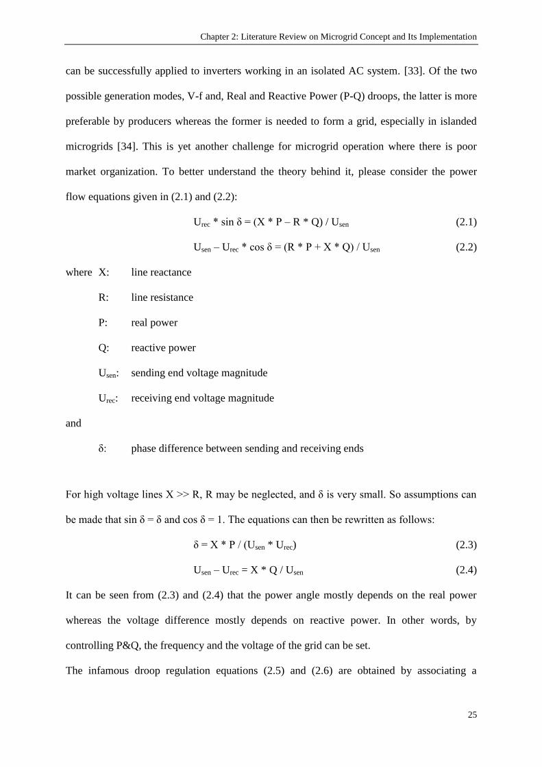
Chapter 2: Literature Review on Microgrid Concept and Its Implementation
25
can be successfully applied to inverters working in an isolated AC system. [33]. Of the two
possible generation modes, V-f and, Real and Reactive Power (P-Q) droops, the latter is more
preferable by producers whereas the former is needed to form a grid, especially in islanded
microgrids [34]. This is yet another challenge for microgrid operation where there is poor
market organization. To better understand the theory behind it, please consider the power
flow equations given in (2.1) and (2.2):
Urec * sin δ = (X * P – R * Q) / Usen (2.1)
Usen – Urec * cos δ = (R * P + X * Q) / Usen (2.2)
where X: line reactance
R: line resistance
P: real power
Q: reactive power
Usen: sending end voltage magnitude
Urec: receiving end voltage magnitude
and
δ: phase difference between sending and receiving ends
For high voltage lines X >> R, R may be neglected, and δ is very small. So assumptions can
be made that sin δ = δ and cos δ = 1. The equations can then be rewritten as follows:
δ = X * P / (Usen * Urec) (2.3)
Usen – Urec = X * Q / Usen (2.4)
It can be seen from (2.3) and (2.4) that the power angle mostly depends on the real power
whereas the voltage difference mostly depends on reactive power. In other words, by
controlling P&Q, the frequency and the voltage of the grid can be set.
The infamous droop regulation equations (2.5) and (2.6) are obtained by associating a

Chapter 2: Literature Review on Microgrid Concept and Its Implementation
26
permissible error on the voltage and frequency values with real and reactive power values.
When there is a variation in the frequency or the voltage value, the DGs adjust their real and
reactive output values accordingly. The adjustment should be done and the power mismatch
should be recovered immediately to maintain the system frequency. Consequently, storage
devices are needed for a successful droop control implementation [32, 35].
ƒ – ƒ0 = –kp(P–P0) (2.5)
Usen – U0 = – kq(Q–Q0) (2.6)
where ƒ: frequency and ƒ0: rated frequency
U0: rated grid voltage
P0, Q0: set real and reactive power of the inverter
The power sharing of the generators are mostly indirectly proportional to their capacities. The
load sharing coefficient mPi is based on an equitable load share in the form:
mP1* P1 = mP2 * P2 = mPi * Pi = constant (k) (2.7)
where Pi is the rated output power of ith DG [36]. It is worthy to note that this scheduling
scheme does not take technical or financial aspects into account. That is to say, DG‟s ability
to provide sufficient level of reserves or the economical outcome is not considered in
determining new droop operating points. In tackling this issue, [37] acknowledges the
economic importance of selective sharing among DGs and proposes using four different
droop coefficients based on production cost or available reserves. Although this improves the
droop performance, it has stability concerns since the increase of droop coefficients beyond
certain limit triggers instability [38, 39].
Another shortcoming of droop control presents itself when implemented in low voltage
networks. For low voltage wires, X >> R assumption does not hold [40] and classical droop
equations are insufficient. The control system proposed in [41] considers the effect of R and

Chapter 2: Literature Review on Microgrid Concept and Its Implementation
27
uses improved droop equations. Another improvement presented in [37] is controlling not
only the fundamental component of the voltage but also its harmonics. Systems proposed in
[36, 41-44] have droop control for harmonic components and thus can feed non-linear loads.
In order to address the versatile nature of microgrids, the central controller in [45] calculates
droop lines for every different condition, shown in Figure 2.2, and updates them. This gives
the controller the flexibility it needs to respond varying operation modes.
Figure 2.2. Different droop lines and operating points in [45]
The conventional droop method employs low-pass filters to calculate average P & Q values,
hence it has a slow dynamic response [46]. A wireless controller was proposed in [47] to
enhance the dynamic response with integral-derivative term addition. Furthermore, the power
sharing is degraded when the sum of output and line impedances are not balanced [48]. This
might be solved with interface inductors or with control loops that emulate lossless resistors
and reactors as in [49].
There are alternative drooping schemes available in the literature. For example, [50] proposes
a control scheme that droops microgrid output voltage with real power (P) and system
frequency (ƒ) with reactive power (Q). This is in stark contrast with conventional load
sharing schemes [29, 51]. However, this system can only be used for only one voltage source

Chapter 2: Literature Review on Microgrid Concept and Its Implementation
28
inverter (VSI) and another scheme called voltage-power droop/frequency-reactive power
boost (VPD/FQB) control is proposed in [43]. This scheme also droops the voltage reference
against real power output and boosts the frequency with reactive power output. In addition to
that, it can be run in parallel with other VSIs and the utility grid itself.
Other controls include controlling resistive output impedance of the inverters and realizing
load-sharing with wireless load-sharing controllers [48, 52] or running all inverters in grid-
following mode even if the microgrid is islanded [53]. The system in [35] has two level
control design which implements droop control for system level multiple DG coordination
controllers and L1 control theory for device-level inverter controllers. This realizes a more
reliable, robust and stable microgrid control.
2.3.2. Protection
The protection of microgrids has been examined in two aspects; islanding detection and fault
current protection. Although these two concepts are intertwined the research work has been
carried out separately. The following two sub-headings describe them in detail. It shall
suffice to mention here that both of these concepts are very important for safe and reliable
microgrid operation [54]. Islanding detection is important for several microgrid management
purposes as well as protection. The fault current contribution of the interconnected power
grid and other adjacent microgrids play a major role in the programming of protective
devices. Therefore, the detection of islanded or grid-connected operation is vital from
microgrid protection point of view [55].
2.3.2.1. Islanding Detection
Islanding is a situation that occurs when part of a network is disconnected from the utility
grid but is still energized by one or more DGs [56]. In conventional distribution networks, in
the case of a fault in the transmission system, the distribution network does not receive any
Chapter 2: Literature Review on Microgrid Concept and Its Implementation
29
power. However, with the introduction of DGs, this presumption is not valid any more [57].
This phenomenon of unintentional islanding may cause some of the following issues[58]:
Safety issues since a portion of the system remains energized when it is not expected;
Loss of control over system frequency and voltage levels;
Insufficient grounding of the islanded network over DG interconnection
Out of phase re-closure problems which may damage the equipment [59]
Because of these issues, a DG unit should pass either one of the two anti-islanding standard
tests, UL 1741[60] or IEEE 1547 [61] before it can be installed. Moreover, almost all utilities
require DG units to be disconnected from the grid as soon as possible in case of islanding
[62]. IEEE 929-1988 standard [63] requires the disconnection of DG units once the microgrid
is islanded. The IEEE 1547-2003 standard on the other hand requires all DGs to be shut down
after a maximum delay of 2 seconds once islanding is detected. In order to achieve this, there
must be a fast and reliable islanding detection method. There are various kinds of islanding
detection methods in the literature which are studied under two sub-headings; remote and
local techniques. The local techniques include three types which are: passive, active and
hybrid detection methods.
Passive detection methods measure some local parameters such as voltage, frequency, total
harmonic distortion [57, 64], rate of change of power signal [65], rate of change of frequency
over power. By comparing these values with pre-determined thresholds, islanding is detected.
Passive detection methods detect islanding very fast and without disturbing the system.
However, should the mismatch be small they become unreliable. The challenge of setting
suitable thresholds and the large non-detection zone are the major drawbacks [16] of passive
methods.

Chapter 2: Literature Review on Microgrid Concept and Its Implementation
30
Active detection methods try to address the shortcomings of passive methods by intentionally
introducing perturbations into the system and detecting islanding according to the response of
the system [66, 67]. In this way, it is possible to detect islanding even if the power mismatch
is very small hence a much smaller non-detection zone. The downside of active methods is
that they are not as fast as passive methods and they degrade the power quality with the
injected perturbations.
Hybrid detection methods are the combination of passive and active methods. The system is
constantly monitored with passive methods and if islanding is suspected by the passive
methods then the active methods are implemented. This combines smaller non-detection of
active methods whereas unnecessary disturbance in the system is prevented by passive
methods [57, 68]. The drawback is long detection time since both of the methods are
implemented.
There are communication based approaches to islanding detection with an effort to overcome
the problems posed by active and passive detection methods. These methods are based on a
direct communication between the utility and DGs in a microgrid [69]. Islanding is caused by
opening of a line circuit breaker so it is proposed to use this event to detect islanding and
execute necessary protection schemes. Some of the methods that incorporate this principle
are [70]: Power Line Carrier (PLC) Communications , Supervisory Control and Data
Acquisition (SCADA), Intertripping/Disconnection signal. These methods do not suffer from
non-detection zones and they do not affect the power quality by de-stabilizing the system.
The only set back is the additional cost of communication systems and their reliability.
According to [71], PLC communication is a practical, reliable and cost-effective method to
realize islanding detection. In this method, a signal is injected to bus bars at substations and

Chapter 2: Literature Review on Microgrid Concept and Its Implementation
31
DGs operate as long as they receive the signal. Should a tripping occur and the microgrid
become islanded, the signal vanishes and DGs are shut down automatically [69].
2.3.2.2. Fault Current Protection
Integration of DGs to the grid and increasing penetration levels of DGs change the fault
current levels and direction in networks [4, 72]. Traditional protection schemes shall be re-
designed in order to meet these fundamental changes. Also microgrids have dynamic
structures, i.e. several DGs and loads connect/disconnect at any instant, and various operating
modes. Fault current levels may vary for all these situations and current protection designs
are not sufficient to tackle these issues. Some of the prominent protections issues are: short
circuit power, fault current level and direction, device discrimination, reduction in reach of
over-current relays, nuisance tripping, protection blinding etc. [73-76].
Protection of microgrids against fault currents and design of new protection schemes are
promising research fields. In conventional power networks, the power flows from higher
voltage levels to lower voltage levels. In case of a fault, the short circuit current decreases as
the distance from the source increases. However, DGs change these concepts as there may be
power flow from the microgrid to the utility if the local generation exceeds local
consumption. As Figure 2.3 shows the fault current may grow downstream with the
contribution of fault currents from DGs. Fault contribution from a single DG may not be
large; however the combined effect of several DGs can reach significant levels [77].
Estimating this contribution is not an easy task as it highly depends on the type of the DG.
Another problem is that DGs with PE interface do not supply short circuit currents sufficient
enough to trigger protective devices [78]. If the fault current settings of the relays are
decreased so that they sense fault currents from inverter-interfaced DGs, then undesired
trippings and nuisance trippings will occur due to transients in the system [79]. The position

Chapter 2: Literature Review on Microgrid Concept and Its Implementation
32
of a fault with respect to DG also affects the operation of protection system. It may be that
the relay is only measuring some part of the actual fault current as there may be several fault
current paths towards the fault [80]. Fault current challenges shall be discussed in detail, in
the next chapter where the conceptual design of the proposed system is explained.
Figure 2.3. Grid and DG fault current contribution in MG
Moreover, fault currents are different for grid-connected and islanded modes of operation. In
the former case, the utility grid contributes to the fault current whereas the latter only
includes the fault currents from DGs. In an islanded grid, the storage devices, intermittency
of DGs such as solar panels or wind turbines, load types and their power demand affect the
fault levels. The new protection system should be dynamic and respond to those changes in
the operation conditions [81, 82].

Chapter 2: Literature Review on Microgrid Concept and Its Implementation
33
Furthermore, low voltage systems may have single phase loads which will alter the balanced
system parameters [83]. DC microgrids which have simpler connection and more efficient PE
interfaces need special attention [84, 85]. Protection of microgrids against over voltages [86]
or utility voltage sags [87] are also amongst popular research fields. Fault current protection
in microgrids and the related challenges are the main focus of this research. Therefore, more
comprehensive discussions on fault current protection challenges, the impact of DGs and
proposed solutions are discussed in other chapters such as Chapter 3 and Chapter 4.
There are different solutions proposed in the literature for the issues stated above. There are
proposals to change the relay types used or update their operating currents regularly or to re-
design the protection techniques from scratch. The use of anti-islanding frequency relays is
proposed in [88]. It is argued that frequency relays can satisfy anti-islanding and frequency
tripping requirements. It is pointed out in [89] Rate-of-Change-of-Frequency (RoCoF) relays
are more reliable in islanding detection under small power imbalances but Vector Surge
relays are yet more susceptible to faulty operation.
However, these solutions are not feasible as it is not realistic to assume that all relays can be
replaced [74]. Alternatively, the method in [90] can be implemented where operating points
of relays are calculated with modified particle swarm optimization. In another approach,
instead of using relays and circuit breakers blindly, some smart algorithms are implemented
to selectively operate relays and isolate the fault [91-93]. There are more ground-breaking
systems which employ a developed communication system to follow the system parameters
and carry out necessary calculations [73, 94]. These systems consider the fact that microgrids
will have extensive communication feature and make use of it. Figure 2.4 shows a new
generation microgrid protection system which relies on the use of communication lines. This

Chapter 2: Literature Review on Microgrid Concept and Its Implementation
34
generic structure is given in [82] as a general framework to be used as a template in future
microgrid protection systems. It categorizes different grid components under separate
headings and shows what kind of additional devices might be required to sustain the required
communication infrastructure. This approach strives to design the communication hierarchy
for protection and management purposes.
Figure 2.4 General Structure of New Generation Microgrid Protection Systems [82]
According to given design, microgrid management system (MMS) is an interface agent
between individual grid components and distribution management system (DMS). This
higher management entity, in turn, takes part in higher levels of cooperation in microgrids
such as Virtual Power Plants (VPPs) or Energy Markets. This work is very comprehensive
for providing a generic structure for microgrid protection systems, determining the placement
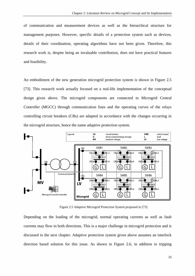
Chapter 2: Literature Review on Microgrid Concept and Its Implementation
35
of communication and measurement devices as well as the hierarchical structure for
management purposes. However, specific details of a protection system such as devices,
details of their coordination, operating algorithms have not been given. Therefore, this
research work is, despite being an invaluable contribution, does not have practical features
and feasibility.
An embodiment of the new generation microgrid protection system is shown in Figure 2.5
[73]. This research work actually focused on a real-life implementation of the conceptual
design given above. The microgrid components are connected to Microgrid Central
Controller (MGCC) through communication lines and the operating curves of the relays
controlling circuit breakers (CBs) are adapted in accordance with the changes occurring in
the microgrid structure, hence the name adaptive protection system.
Figure 2.5 Adaptive Microgrid Protection System proposed in [73]
Depending on the loading of the microgrid, normal operating currents as well as fault
currents may flow in both directions. This is a major challenge in microgrid protection and is
discussed in the next chapter. Adaptive protection system given above assumes an interlock
direction based solution for this issue. As shown in Figure 2.6, in addition to tripping

Chapter 2: Literature Review on Microgrid Concept and Its Implementation
36
characteristics, each relay is assigned with an interlock direction. When a fault occurs, relays
compare the flowing fault current with the pre-assigned interlock direction and thus isolate
the fault. This is achieved between the last relay in which fault current direction and interlock
direction are the same, and the first relay in which the fault current direction is opposite of
interlock direction.
Figure 2.6 Implementation of Selectivity with interlock direction in [73]
However, the major drawback of this approach is the need to know possible microgrid
structures beforehand. This is required to arrange tripping characteristics of the relays as well
as to assign their interlock directions in accordance with the expected operating current flow.
It is required to study the possible structures of this microgrid and tabulate the necessary
parameters. Then, the protection system will update these parameters accordingly. This is a
major drawback because a new structure or a connection in this microgrid as well as a new
deployment will render the whole adaptive protection system useless. Each new deployment
requires the parameter tables to be updated with a new entry.

Chapter 2: Literature Review on Microgrid Concept and Its Implementation
37
Following from the example given above, current systems use some sort of database or event
table to search the current status and take pre-determined precautions [73, 90]. However,
since microgrids are designed to accommodate new generators and loads, their structure is
bound to change very often. Therefore, these schemes are not practical. Some sort of
algorithm which manages to adjust the protection scheme to the new state of microgrid is
direly needed. Machine learning, artificial intelligence or fuzzy logic algorithms are the
trivial candidates as a foundation for such adaptive-automatic microgrid protection schemes.
All of these new approaches would necessitate the use of communication lines in microgrids.
Despite providing many advantages, use of extensive communication is not all good news for
power networks. It is discussed in the literature that having extensive communication
networks would make the microgrid more expensive and less reliable [95]. Moreover, in a
distributed energy system, components may be located far away which makes communication
difficult [38]. Another communication challenge is posed by the existence of different
manufacturers and models for grid components. The communication between them shall be
regulated by certain set of rules so that all grid devices use the same variables and parameters
for coordination purposes. Simply put, a standardized communication framework is required
to make sure that these grid components speak in the same language. In this manner
equipments from different vendors and with different capabilities can be modeled in a
standard manner. This phenomenon is explored in detail in Section (2.5) in this chapter and
the relevant modeling is given in Chapter 6. To solve this issue, Standard communication
protocols such as the IEC 61850 [11] might be used in these microgrid protection systems as
in [96], however it is of concern that how the new fault currents and fault levels shall be
calculated for any change occurring in the system.

Chapter 2: Literature Review on Microgrid Concept and Its Implementation
38
It is important to define a set of data and information exchange models for the
communication of data within power networks for protection and automation purposes. This
has been partly achieved by the introduction of IEC 61850, which mainly focuses on the
standardization of data to be communicated within substations for various purposes including
protection. IEC 61850 focuses mainly on substation communications. But, the work
presented in this thesis investigated the possible uses of this standard for the protection of
microgrids.
There are conceptual designs or proposed opinions in the literature while it is hard to find a
new protection design in a microgrid which responds to the needs of microgrid operation
modes and components. The biggest challenge is to have a dynamic protection system which
discovers new deployments and structure changes in the microgrid automatically, and update
the operating parameters of protective devices. There is a strong need for plug-and-play
concept in microgrids, at least from protection point of view. Furthermore, the possibility of
having differing sets of microgrid components should also be taken into account during the
design of a protection system. These points are yet to be addressed in the literature.
Consequently, the author focused his research project on these points to come up with a
generic yet practical, comprehensive yet standardized and universalized microgrid protection
system.
2.3.3. Microgrid Energy Management System (MEMS)
In order to execute the duties described so far, a microgrid utilizes a microgrid management
system. This system ensures that different components of the microgrid are managed to serve
towards a certain objective [97]. It typically comprises of three hierarchical levels of control
as shown in Figure 2.7.

Chapter 2: Literature Review on Microgrid Concept and Its Implementation
39
Microgrid Central Controller (MGCC) acts as an interface between the microgrid and the
outside world. It communicates with Distribution Network Operator (DNO) and Market
Operator (MO) and optimizes microgrid operation through Local Controllers (LCs). It
ensures that in a network where more than one microgrid exists, microgrids work in harmony
to sustain a reliable and safe operation. LCs are responsible to control components of a
microgrid such as distributed generators, storage devices, loads or protection equipment.
MGCC manages LCs and updates their operation modes and points in parallel with the events
occurring in the network and/or the microgrid. Once the updates are received, LCs mostly
behave autonomously until a new instruction is received from MGCC [98]. Based on the
decision making scheme, the control systems (also known as supervisory systems [8]) are
categorized as centralized and decentralized microgrid control [99].
Figure 2.7. Control Levels of the Microgrid [100]
Centralized control strives to maximize the local production according to market prices. For
this to occur, there is a two-way communication between the MGCC and each LC [8].
Starting from this point there is a new concept called Virtual Power Plants (VPPs) where
distinct entities inside a microgrid are controlled by a central unit to act as a power plant
[101].

Chapter 2: Literature Review on Microgrid Concept and Its Implementation
40
Conversely, in decentralized control, the larger part of the decision making is in the hands of
LCs. They act in a smart fashion and communicate with each other to increase the revenue
and the performance of the microgrid. The most popular way to design this intelligent system,
which is composed of smaller less intelligent components, is by using multi-agent systems
[100]. Multi-agent systems are already proposed for the protection [102], stabilization [103],
restoration [104]of large power systems.
There are on-going research projects being carried out to investigate alternative control
systems. A control system based on „Game Theory‟ is proposed in [105]. In this approach,
power electronics based inverters are treated as variable impedance loads and every generator
in the microgrid is taken as a player. The stabilization and the control of the system may be
achieved through real-time or turn-based games. For different scenarios, different games such
as “Maximum Power Game” or “Microgrid Stability Game” can be played. Depending on the
level of communication, games might be cooperative and non-cooperative.
In an another study, the “Ant Colony Optimization” algorithm is proposed to solve constraint
satisfaction problem for microgrids [106]. Ant colony optimization is a nature-inspired
artificial intelligence technique where several ant colonies cooperate to solve a problem
[107]. In microgrid applications, distributed generators, storage devices and loads are
represented by a variable. The domain of each variable represents the quantized operating
points at which the generator or load could be commanded to operate [106]. By stipulating
constrains, ants walk on the construction graphs and each variable will be assigned an
operating point. The touring of the colonies continue until the solution is attained for each
and every variable.

Chapter 2: Literature Review on Microgrid Concept and Its Implementation
41
By implementing a central control unit in microgrids, different objectives can be realized.
Minimizing system disturbances, maximizing efficiency, meeting power demands from local
resources, stabilizing the system are to name a few. This formulation outlines the difficulty of
the control task. With competing objectives and highly variable parameters, a real-time power
management system which is both robust and flexible is needed.
Microgrid Energy Management Systems (MEMS) which are aimed at controlling the
microgrid in a holistic sense are fairly new in the literature. Although the very concept of
MEMS is proposed some time ago [5], real design and implementation of MEMS are crucial
to get more knowledge and experience in the field. Conceptual designs look appealing but
implementations or simulations on models shall be carried out to see the real side of the
picture[14].
Microgrids have dynamic structures which change more often than the conventional large
networks. This dynamic behavior of microgrids is a major protection challenge since the
conventional selectivity methods assume a fixed network structure and a predetermined relay
hierarchy [108]. Whenever restructuring occurs, the selective levels assigned prior to that
become erroneous. For a proper operation, the selective levels of relays should follow the
changing conditions of the network. Whenever a structure variation takes place in a
microgrid, new relay hierarchy should be extracted and corresponding settings including time
delays should be determined before updating these settings within the relays via
communication lines [109, 110]. It is essential that this process is performed automatically so
that the processing time is minimal and there is no interruption in power delivery. This
requires an algorithm which will determine the current structure of the system and yield the
relay hierarchy at all branches of the network.

Chapter 2: Literature Review on Microgrid Concept and Its Implementation
42
In order to ensure protection under these conditions, a centralized management is required to
monitor and communicate with the microgrid components and assign suitable operation
parameters. It is almost impossible to know the parameters of a microgrid beforehand.
Therefore, a centralized microgrid management system is required for monitoring the grid
components, their operating points, new deployments and connection changes occurring in
the microgrid. Then, necessary adjustments can be made by the MEMS and through
communication lines related protective devices can be programmed accordingly.
2.4. Examples around the World
There are various microgrid implementations or active experiments worldwide to understand
the operation of microgrids in a better sense. Different technologies and topologies have been
studied for different purposes. Some of the experiments are run for purely R&D purposes
whereas others are deployed on islands or isolated/distant grids. Since the microgrid concept
is very versatile, the experiment conditions and the objectives have a very wide span.
2.4.1. European Union (EU)
The level of climate change awareness in the EU is very high and there are certain targets that
need to be achieved by the member states by 2020. There are various directives passed by the
European Parliament such as 2001/77/EC, 2003/30/EC and 2006/32/EC. These directives
stipulate that the carbon emissions shall be reduced by certain amounts, the share of
renewable energies in the energy market shall be increased and the energy consumption shall
be reduced by increasing energy efficiency [111]. Accordingly, there are incentives from the
EU and several on-going projects in member states.
The first project funded by the EU was the “Microgrids Project” and it was undertaken by a
consortium led by National Technical University of Athens (NTUA). The objective was to

Chapter 2: Literature Review on Microgrid Concept and Its Implementation
43
investigate the dynamics of DGs in microgrids and develop strategies for a number of issues
such as control algorithms, protection schemes, black start strategies as well as definition of
DG interface response and intelligence requirements [9]. A pilot installation was realized on
the Kythnos Island, Greece. A comprehensive study on microgrid control methods was
performed in ISET microgrid, Germany [112]. The continuation of the project was “More
Microgrids Project” again undertaken by a consortium led by NTUA. This project was
executed to study alternative methods, strategies along with universalization and plug-and-
play concepts. The demonstration site is an ecological estate in Mannheim-Wallstadt,
Germany [113].
Other implementations with smaller scales include the Labein Microgrid in Spain, Frielas
Feeder in Portugal, CESI Microgrid in Italy, Continuon Holiday Camp Microgrid in the
Netherlands, Am Steinwag Settlement in Germany [6, 9, 113].
2.4.2. Japan
Japan is committed to utilize RE systems, however this puts the country‟s well-earned high
power quality reputation in jeopardy. The RE systems used in Japan are mostly wind turbines
and PV systems, intermittent nature of which is an additional set-back. Microgrid‟s ability to
address these problems motivated the projects in Japan and hence the country has the most
microgrid implementation projects worldwide [114]. Most of the projects are funded by the
New Energy and Industrial Technology Development Organization (NEDO). Three
demonstrations sites were installed in 2003 under NEDO‟s Power grid with renewable
Energy Resources Project.
The first project started operation in 2005 World Exposition in Aichi although it is removed
to Tokoname City near Nagoya in 2006. This system uses fuel cells, PV panels and NaS

Chapter 2: Literature Review on Microgrid Concept and Its Implementation
44
battery storage system. This microgrid is used to feed some major pavilions and it was put to
test twice for independent operation in 2005 and 2007. Although the first test revealed some
deficiencies in controlling the voltage and frequency, the second experiment was more
successful [114]. The second demonstration site is in Kyotango where a biogas plant is
connected to two PV systems and a small wind turbine. This network operates as a VPP and
interestingly instead of the latest technology the communication is realized over conventional
information networks such as ISDN and ADSL [6, 9]. The third project in Hachinohe is being
undertaken by the Mitsubishi Research Institute and Mitsubishi Electric [115]. This system
has its private distribution line and consists of PV systems, wind turbines, gas engines and
storage. The management scheme developed here ensures stability and meets building
demands. An additional project has been started by NEDO in Sendai city where four levels of
customer power will be studied. The system will have power quality backup system in order
to reduce interruptions and voltage drops. This project is aimed at studying the possibility of
supplying different service levels to customers in the same area. The system has enhanced the
power quality since it was put into action in 2007 [10].
There are several private microgrid research projects. For example, the Shimizsu Microgrid is
being developed by the Shimuzu Corporation with the cooperation of the University of
Tokyo to develop an optimum operation and control system. Tokyo Gas on the other hand,
again partnering with the University of Tokyo, is trying to develop an integrated DG control
through simulations and experiments at its facility in Yokohama [10]. Crossing boundaries,
Mitsubishi Corporation has installed a small grid in Hsinchiang, China and it can be supplied
by distribution network, PV systems, battery storage and genset operation [116].
2.4.3. Korea
Korea‟s first and only pilot project is being developed by the Korean Energy Research

Chapter 2: Literature Review on Microgrid Concept and Its Implementation
45
Institute (KERI). The test system is very comprehensive as it includes several types of DGs
such as PV simulator, fuel cells, diesel generators, wind turbine simulator along with
significant and non-significant loads. The network is equipped with storage and power
quality devices. An energy management system is being implemented which even takes
weather conditions into account and communicates with the components through a gateway.
Being equipped with rich mixture of components, the KERI microgrid is aimed at testing and
studying almost all aspects of microgrids. The whole project was implemented in two phases
where in the first phase, the microgrid was kept as a 100 kW class plant and in the second
phase it was extended for further studies [117].
Jeju Island is receiving increasing attention due to its immense potential for RE resources.
The total wind power energy in Jeju was only 19 MW in 2006 and it has increased to 230
MW in 2009 whereas several fuel cell plants are either constructed or planned on the island
[118]. Jeju Island and similar Korean islands are prime candidates for microgrid
implementations in Korea in the future [119].
2.4.4. North America
CERTS (the Consortium for Electric Reliability Technology Solutions), shown in Figure 2.8
[6], is the most well-known of U.S. microgrids. It is a collaboration between AEP,
TECOGEN, Northern Power Systems, S&C Electric Co, Sandia National Laboratories and
the University of Wisconsin [6]. It consists of several DGs and a thyristor based switch to
allow isolation from the grid. The main objective of this research was to facilitate easy
connection of small distributed generators to the network. As a result, three advanced
concepts, also referred to as the CERTS microgrid concept, have been developed and
demonstrated to decrease the field engineering work on microgrids. These concepts can be
listed as a method to ensure automatic and seamless transition between grid connected and

Chapter 2: Literature Review on Microgrid Concept and Its Implementation
46
islanded modes, a protection method inside the microgrids which does not depend on high
fault currents and a microgrid control scheme to stabilize system frequency and voltage
without utilizing high speed communication [120].
Also, two software tools, which are required for microgrid deployment, are being developed
in relation with CERTS project. These are µgrid Analysis tool (µGrid) developed by the
Georgia Institute of Technology and the Distributed Energy Resources Customer Adoption
Model (DER-CAM) in use at the Berkeley Lab [9].
Figure 2.8. CERTS Microgrid [6]
There are other implementations going on in Mad River Waitsfield by Northern Power
Systems [121] , British Colombia Institute of Technology Microgrid [122] and the General
Electric Microgrid [6]. These systems are currently at R&D stage and the objective is to
design control and protection strategies for different types of microgrids.
2.4.5. Australia
Currently, there are no microgrid pilot projects in Australia but there is a large potential, and
with the Government‟s incentives, extensive research on distributed energy and microgrids
has recently started [123]. Australia is a very vast continent-country which has many isolated
communities. It is a new trend in the Australian Electricity Market to utilize RE resources for

Chapter 2: Literature Review on Microgrid Concept and Its Implementation
47
local power generation and local consumption. Some of these communities are not only far
away but also lack access roads to the weather conditions. Utilization of DGs and
implementation of microgrids for that purpose will ease the transmission and distribution
burden on service providers. The ultimate goal is to realize the design and provision of power
station infrastructure which will be optimized to suit the unmanned status of the power
stations [124]. The Yungngora and Kalumburu communities in Western Australia [125], and
the Windorah community in Queensland [126] are examples of such distant communities
which are candidates for microgrid operations. In addition to this, some energy companies are
trying to operate microgrids on islands such as Thursday Island in Queensland [126] and
King Island in Tasmania [25].
2.5. Standards and Universalization
Proper integration of DGs to the electric power systems is needed since these systems are not
designed to accommodate active generation and storage at the distribution level [127]. The
evolution of DG was not pioneered by a single organization or a company rather every
institution runs its own R&D project. As a result, there are many different types of DGs,
interconnections, electronics interfaces. This makes it incredibly difficult to draft a set of
rules/guidelines for DGs interconnection and utilization. In an effort to tackle this issue, there
are several standardization and universalization works performed by several bodies. The
ultimate objective is to standardize certain aspects of DGs and microgrids while there is no
technology or design constraint stipulated to hinder the versatility of these concepts. Some of
these standards, shown in Figure 2.9, are in force while others are still in drafting phase
[128].
The first standard prepared was about the rules governing the connection of DGs to the
electric power system. For a DG to be connected to the grid, it has to conform with

Chapter 2: Literature Review on Microgrid Concept and Its Implementation
48
requirements of IEEE Standard 1547.1 [61]. Only for this purpose, an alternative standard UL
1741 [60] can also be used. Both standards require that in the case of islanding, all DGs shall
be disconnected from the islanded microgrid. This does not take full advantage of DGs nor is
it possible to conform with this requirement if islanded operation is desired [99]. For this
reason, another part to the IEEE standard 1547, namely 1547.4, is being drafted which
focuses on integration of islanded systems with the utility.
Figure 2.9. IEEE SCC21 1547 Series of Interconnection Standards [61]
The part 1547.4 is being treated as one of the fundamental standards to play a key role for
microgrid standardization as it covers vital planning and operating aspects such as impacts of
voltage, frequency, power quality, protection schemes and modifications, the characteristics
of the DER, reserve margins, and load shedding [129]. The part 1547.3 is about monitoring
and communication of DGs. Its purpose is to facilitate the interoperability of DGs in an
interconnected system.

Chapter 2: Literature Review on Microgrid Concept and Its Implementation
49
IEEE Standard Coordinating Committee 21 (SCC21) is well aware of the developments in
the electricity sector and it constantly supports the development of new standard drafts.
Initially, IEEE 1547 standard covered DGs with capacity less than 10 MVA [127]. However,
with the recent developments in technology, there are systems with larger capacities. The
draft standard 1547.5 is aimed at preparing guidelines for such systems which are not covered
by the IEEE 1547.1. The draft standard 1547.6 considers interconnection of distribution
secondary network system types of area electric power systems (Area EPS) with DG. 1547.7
is a very significant step towards standardization and universalization in microgrids and DGs.
It covers the necessary methodology, testing steps and aspects to assess the impact of a DG
on the system. This study will be helpful for network operators, contractors, and regulatory
bodies to understand the impact of a particular DG on the network after connection.
In a larger scale than that of the 1547.7 draft, a “Microgrid Citizenship Tool” is proposed in
[1] to evaluate how a microgrid will appear to the grid. This tool assesses a microgrid‟s good
citizenship level based on the three key characteristics: generation capacity, installed storage
and load. A microgrid is classified as a good citizen if it contributes to the performance of the
grid with a consistent profile whereas a microgrid with high transient and unpredictable
variations will represent a bad citizen. Such a method may be utilized in electricity market as
a useful tool to estimate the impact of a microgrid on the network. If a standard methodology
is developed, such a concept will be an indispensable part of standardized microgrid
assessment and planning process.
National Renewable Energy Laboratory (NREL), in the USA, conducted research on
interconnection, grid effects and tariff design for DERs and one of the areas was “Advanced
Universal Interconnection Technology”. It is believed that universalized interconnection DGs
Chapter 2: Literature Review on Microgrid Concept and Its Implementation
50
will facilitate the connection with EPS [97]. The objective is to design a modular interface
device which will respond the power electronics requirements of any DG system and provide
interconnection interface in a safe, reliable and cost effective manner [130]. A prototype was
developed by the Northern Power Systems (NPS) which manages power management,
conditioning and relaying functions with a DSP-based architecture. It was designed to be
compatible with different circuit breakers, switching technologies, RE based DGs and
conventional generators [131]. The research outcomes were promising and a new design with
cost reduction as the primary objective is planned.
As outlined in the preceding sections, there is a growing interest in extensive communication
for network management, control and protection purposes. However, there is no consensus in
the literature about which communication protocol shall be used in these systems. It is known
that communication devices and systems will add to the complexity of microgrids and this
may constitute some problems. For this reason, worldwide collaboration is required in
identifying a universal or standardized communication protocol that shall be used in
microgrids for DGs, storage and protection devices to tackle the arising problems.
IEC 61850 is an international communication standard aimed at reaching a universal
communication infrastructure in electrical systems [132]. It uses Object Oriented (OO)
modeling for the equipment and their functionalities. IEC 61850 effectively reduces the
burden of communication infrastructure modeling by virtual modeling of physical devices in
a standard manner. Furthermore, it also defines necessary procedures for data transfer and
client/server interactions between the equipment in an electrical network. IEC 61850 was
released in 2003 for the first time for a communication within a substation automation
system, yet it has been used for other purposes [133]. With a vision of controlling DGs, it has

Chapter 2: Literature Review on Microgrid Concept and Its Implementation
51
been extended. The first release, IEC 61400-25 was about the communication in wind power
[96]. Two more extensions IEC 61850-7-410 on hydroelectric power plants and IEC 61850-
7-420[12] on DERs logical nodes have also been published. These two extensions might be
used in designing the communication system of DGs in detail. This standard and its
utilization for microgrid protection systems have been examined in detail, in chapter 6 of this
thesis.
For microgrids to be embraced rapidly and implemented easily, there is need for systematic
standardization and universalization. This would not only help in bringing different
organizations together but also encourage more people towards microgrid transition. If
standard procedures are implemented and universalized components/interfaces are utilized
instead of re-inventing the wheel for every single microgrid project, past experiences can
easily be put into practice.
2.6. Impact of Electric Vehicles (EVs) on Future Microgrids
The internal combustion engines, which provide the traction for vehicles for the past century,
can only give a maximum efficiency of 30 % [134]. Considering the increasing oil prices, an
alternative to fuel is necessary for a sustainable transportation. This is also desirable for
security policy of many countries since it decreases the dependency on foreign oil [135, 136].
These factors have increased the interest in EVs dramatically[137]. All the technology
required for EV is readily available and the research focuses on improving performance or
efficiency [134].
When coupled with the smart grid technology, an EV can act as a load as well as a distributed
storage device[138]. Being connected to the grid when not in use, battery of the EV can
supply power at peak load times and thus increase the power reliability of the grid. This

Chapter 2: Literature Review on Microgrid Concept and Its Implementation
52
technology is called V2G [139]. Considering the total number of vehicles in a locality,
distributed storage capacity provided by V2G can have very large impact on the economical
operation of smart grids[140]. In the light of this information, it can be expressed that EVs
will become an indispensable part of future microgrids.
One major concern about wide EV acceptance is the immediate impact on electricity
networks. Considering the cumulative generation capacity of the power systems and the
estimated EV burden, it is concluded that at power generation and transmission levels, no
major issue is anticipated in power systems [141]. The impact of EV is an issue at
distribution level since it becomes comparable with the parameters therein [142]. It is
discussed in the literature that introducing two EVs to a distribution system is equivalent to
introducing one new house to the neighborhood [143]. If it is assumed that 60 % of the
households have only two cars, a full EV migration will be equivalent to 30 % rise in the
number of the houses in the neighborhood. This is a significant impact on distribution
systems and it shall surely be taken into account by distribution companies.
Impact of EVs as a load is one aspect while the potential distributed storage provided is
another. In summer for instance, following rush hour in the morning most of the vehicles are
parked at parking lots (such as business hub or school/university parking lots). When they are
coupled to the grid, they can support the grid until the rush-hour in the afternoon. EVs,
mostly parked in garages of the owners, can provide energy to the grid throughout the
evening and get recharged during the night [144].
Likewise during winter, EVs can support the grid in the evening when electricity is required
for heating, illumination etc. It is apparent from Figure 2.21 that the peak hours are longer

Chapter 2: Literature Review on Microgrid Concept and Its Implementation
53
and more dominant than summer peak hours. The support of EVs during these shall be very
beneficial. In similar fashion EVs can be programmed to recharge during night.
In short, the availability of the technologies required and the higher efficiency of electric-
driven cars create a genuine interest for EVs in the car market. The dual role of EVs in the
microgrids, i.e. load while charging and distributed storage through V2G, brings many
opportunities as well as challenges. Power flow analyses, reliability, protection and fault
current flow phenomena will change massively with the introduction of EVs. Therefore,
network grid operators and power engineers need to consider the impact of EVs on networks
for future plans.
2.7. Conclusion
The world we live in today is being troubled by the concerns on global warming, pollution
and CO2 emissions. RE systems offer means of generating cleaner and sustainable energy.
However, there are lots of challenges that must be tackled so that RE resources could be
utilized to their full potential. RE resources are mostly dispersed and different generation
approaches should be used to harvest the maximum potential out of those sources. This is
contradictory to the traditional concept of central generation and distribution over large
distances. For this reason, existing grids are not entirely compatible for excessive integration
of DG units. On top of that, micro-scale implementation of known generation plants such as
micro hydroelectric power plants, diesel generators and etc, have similar aspects since they
are also distributed and their generation capacities are much smaller than their traditional
giant counterparts.
In order to achieve a cleaner, reliable, and secure power generation, transmission and
distribution system, the various challenges brought about by this new grid structure and

Chapter 2: Literature Review on Microgrid Concept and Its Implementation
54
management system shall be tackled with similar research projects. The outputs of studies on
microgrids will aid in the development of secure, reliable, and stable real-life small-scale
networks with greater penetration of RE sources. This will aid in achieving a more reliable,
secure and cleaner energy without compromising from environment protection and similar
concepts.
This chapter summarized the current status of the research on microgrids, their management
and operation. As it is stated above, microgrid protection has received relatively less attention
as compared to other research fields. There is a knowledge gap regarding;
i) monitoring the structural changes occurring in microgrids due to connection changes
or new deployments,
ii) adjusting parameters of protective devices according to these changes to ensure proper
and reliable operation,
iii) standardizing the much-needed communication between grid components in
microgrids, and
iv) interaction between different protection schemes applied on microgrids.
Identifying this research opportunity, author has focused his research on these topics.
Consequently, the research work presented in the coming chapters of this thesis is an effort to
address these knowledge gaps pertaining to microgrid protection systems. In a nutshell
throughout this research work, a versatile microgrid protection system with communication
support [55] has been developed. The operating parameters are calculated in on-the-fly and
no prior knowledge of the microgrid structure is required [145]. This system can be extended
to accommodate various types of components such as fault current limiters [146] or EVs
[147], accept new deployments and extract the new microgrid structure with adaptive
computing [7] and can be implemented with international communication standards[148]

Chapter 2: Literature Review on Microgrid Concept and Its Implementation
55
such as IEC 61850 [8] and IEC 61850-7-420 [12]. In order to accommodate all types of grid
components, necessary extensions have been developed for this standard, e.g. for FCLs [149]
and EVs [147].

Chapter 3: Conceptual Design of Centralized Microgrid Protection System
56
Chapter 3
Conceptual Design of Centralized Microgrid Protection System
Publications pertaining to this chapter:
1) Taha Selim Ustun, Cagil Ozansoy, Aladin Zayegh, "A microgrid protection system with central
protection unit and extensive communication," in Proceedings of 10th International Conference on
Environment and Electrical Engineering (EEEIC), 2011, vol., no., pp.1-4, 8-11 May 2011, Rome, Italy,
ISBN 978-1-4244-8781-3.
2) Taha Selim Ustun, Cagil Ozansoy, Aladin Zayegh, "A central microgrid protection system for networks
with fault current limiters," in Proceedings of 10th International Conference Environment and
Electrical Engineering (EEEIC), 2011, vol., no., pp.1-4, 8-11 May 2011, Rome, Italy, ISBN 978-1-4244-
8781-3.
3.1. Introduction
The first step of the methodology assumed in this research work is to devise a conceptual
design for the developed microgrid protection system. This process is the foundation stone of
the overall research work on which the other methodology steps shall build. Therefore,
during this period, different possibilities in microgrid operation, equipment used in power
grids and different operation cases have been investigated. This has been done with the aim
of thoroughly understanding the operational situations that could occur in microgrids and
designing the protection system in a comprehensive manner. Unlike most of the studies

Chapter 3: Conceptual Design of Centralized Microgrid Protection System
57
reported in the literature, instead of focusing on a particular microgrid topology or a
particular case thereof [73, 90, 150-153], this research strives to achieve a flexible protection
system. It is an aim of this research that the designed protection system can be used in
microgrids with different topologies and set of components. It is also desired that the varying
operating conditions, connection/disconnection of components and new deployments can be
handled with this new microgrid protection system.
In order to serve this purpose, different DG types have been investigated. It is a known fact
that rotating-machine type DGs such as wind turbines or diesel generators have different fault
current contributions as compared to IIDGs such as PVs or Fuel Cells [14, 15, 153, 154].
Same type of DGs have different fault current contributions which depend on their operating
capacity [155] and might be manipulated with auxiliary elements such as Fault Current
Limiters (FCLs) [156]. There are devices which may provide power as well as demand it,
such as EVs or storage devices [14]. All this information has been taken into account during
the conceptual design process.
The overall conceptual design has been developed in a fashion to respond to the demands of
new generation microgrids with their various operating conditions and dynamic set of grid
components. Furthermore, this design has been tailor-made to enable the implementation of
the underlying communication exchange using the IEC 61850 standard. This is essential for a
protection system which is intended to be used on different topologies where same devices
might have different manufacturers and models. This design is suitable for automated grid
structure detection whereby the changes occurring in the microgrid topology can be
monitored automatically and necessary actions could be taken. These above-mentioned two
factors have been paid special attention since they are the building blocks of the plug-and-

Chapter 3: Conceptual Design of Centralized Microgrid Protection System
58
play concept in power networks. When these two features are used, this conceptual design
can implement plug-and-play for new grid components connected to the microgrid.
The next section of this chapter explains the fault current challenges in microgrids. Different
protection challenges have been explained along with their representations on microgrid
topologies. Then, Section 3.3 reveals the details of the conceptual design of the developed
microgrid protection system. Section 3.4 sheds light on a very important device, i.e. FCL,
which is bound to be used frequently in microgrids, and its integration to the conceptual
design. EVs and storage devices have the ability to operate as a load or a generator and they
have been implicitly included in the conceptual design in terms of individual generators and
loads. EVs and their implementation shall be discussed in detail in Chapter 6.
3.2. Fault Current Challenges in Microgrids
The recent developments in technology and the growing concerns for global warming
motivated engineers to search for cleaner and more efficient systems. In order to decrease the
impacts of fossil fuel based generation on the environment, the new vision is to generate
electricity from cleaner energy sources and closer to the consumption areas. Consequently,
the power industry is moving towards Distributed Generation (DG), which may be
Renewable Energy (RE) based DG such as wind turbines, solar systems and etc. This also
decreases the burden on transmission lines which already operate close to their limits.
Although DG has recently become irreversibly popular, there are some serious challenges for
the large scale integration to the utility grids. Existing distribution systems are not designed
for significant penetration of DG as they were traditionally designed with the assumption of a
passive network. The interconnection of RE based DG systems to such networks inevitably
changes the characteristics of the system and presents key technical challenges which were

Chapter 3: Conceptual Design of Centralized Microgrid Protection System
59
previously unknown to grid operators and power engineers [2]. Moreover, DG systems also
make contributions to the fault currents around the network. Hence, in case of a fault, the
transient characteristics of the network become completely different [3]. These are only a few
of the issues that have arisen in relation with the revolutionary changes occurring in the grids
and the way they are operated.
In an effort to tackle these problems, the microgrid concept has been introduced [5, 7, 9]. The
motivation behind using microgrids is to divide the enormous conventional utility network
into smaller and more easily operable grids. These smaller electrical networks will manage
distributed generators, loads, storage and protection devices in their own grid. Provided that
each microgrid is operating as a model citizen, i.e. either as a load receiving power or as a
power supply supplying power with stable voltage and frequency, then the overall utility grid
can be operated properly. It is a well-known fact that higher penetration levels of DGs,
especially those that require Power Electronics (PE) interface, alter the grid structure and
jeopardize safe and reliable operation. The microgrid concept is introduced to manage these
generators in smaller quantities rather than trying to tackle the whole network in a holistic
manner. In this way, more DGs can be employed in the grid and side-effects on the grid
operation can be eliminated.
However, there are technical challenges regarding microgrids and their full integration into
existing grids such as control, management and protection [9, 10]. Especially, the
conventional protection schemes totally collapse since two fundamentals of traditional utility
grids, which are the “radial” structure of the grid and passive transmission and distribution
networks, do not hold anymore. Instead of making small amendments in these protection
systems that are no longer applicable, revolutionary changes are required for safe operation.

Chapter 3: Conceptual Design of Centralized Microgrid Protection System
60
The integration of DGs to the grid and the increasing levels of penetration change the fault
current levels and their direction in networks [4, 72]. In conventional networks, transmission
and distribution networks are passive and do not contribute to faults. In a microgrid, DGs will
contribute to fault currents and the contribution level depends on the DG type. So the ratings
of the protection equipment should be re-planned accordingly.
Consider the case shown in Figure 3.1, where a microgrid operates in grid connected mode
and an internal fault occurs at the load just downstream from the relay R3. In a passive
distribution network, the relay R3 ideally needs to interrupt the fault current contribution of
the grid, i.e. IfaultGRID. However, in the case given in Figure 3.1, there will also be fault current
contributions from the DG1 and DG2, namely the IfaultDG1 and IfaultDG2. The rating and the
settings of R3 should therefore be adjusted accordingly to take into account these extra fault
current contributions. When the number of DGs in a system increases, this difference will
obviously be higher.
Figure 3.1. Grid connected-Mode, Internal Three-phase Fault
If an external fault occurs in the same system (a fault outside microgrid), it requires that the
relay R1 opens and islands the microgrid to protect its stability. This requires R1 to detect not

Chapter 3: Conceptual Design of Centralized Microgrid Protection System
61
only downstream faults but also upstream ones. Since faults may occur at different locations
and there may be several DGs at different places, bi-directional operable relays meet the
requirements of microgrid protection much better than traditional unidirectional relays.
Assume that when the microgrid is islanded from the utility, in the case of a power
disturbance such as an under-voltage scenario, an internal fault occurs as shown in Figure
3.2. In this case, there will be no grid fault contribution and the overall fault current will only
be due to IfaultDG1 and IfaultDG2. Relay R3 is now supposed to operate at this fault level, i.e.
IfaultDG1 + IfaultDG2, while in the previous case it was set to trip a much higher fault current, i.e.
IfaultGRID + IfaultDG1 + IfaultDG2. The operating tripping current of R3 should therefore needs to
be adjusted according to the operation mode of the microgrid to ensure proper protection. The
related simulation results are given in Chapter 7.
Figure 3.2. Islanded Mode – Internal Three-phase Fault
Using the lower of the two fault currents as the relay operating current may seem like a good
idea in the beginning. However, this is not necessarily safe or reliable and may cause
unnecessary trippings in larger systems. For example, a microgrid with a different topology is

Chapter 3: Conceptual Design of Centralized Microgrid Protection System
62
illustrated in Figure 3.3. In this grid connected microgrid, if the tripping current of the relay
R2 is set very low then it will trip under normal operating conditions. Alternatively, a small
oscillation in the system will trigger R2 to open. This concept is referred as nuisance tripping
[14]. These erroneous trippings cause unwanted islanded sections in the microgrid and they
may cause power interruption in some parts of the network while there is no fault in the
system. Depending on the complexity and size of the microgrid, if the necessary precautions
have not been taken, nuisance tripping might become a frequent occurrence. This makes
operation impossible and reliability of the network will be put to question. Consequently,
both network operators and consumers would like to eliminate nuisance tripping by setting
correct operating conditions on the relays.
Figure 3.3. Nuisance Tripping
In conventional power networks, the fault current contributions of large generators are much
larger than normal operating currents. Therefore, there is a huge gap between the normal

Chapter 3: Conceptual Design of Centralized Microgrid Protection System
63
operating currents flowing in the network and the trigger currents set for relays to interrupt
fault currents. However, IIDGs do not have very large fault current contributions [14, 15,
153, 154]. For this reason, the trigger current settings of relays are relatively closer to normal
operating currents flowing in the network. This is inevitable for proper operation in networks
with DG penetration. At the same time, it makes nuisance tripping more probable since the
operation gap between trigger currents and normal operating currents is much smaller.
Selectivity is another vital concept in protection systems. It means if the downstream circuit
breaker (CB) fails to interrupt, then the upstream CB with larger capacity should operate and
isolate the fault. It is intended to isolate the fault with the nearest relay so that the rest of the
system will not be affected. For better understanding consider the case shown in Figure 3.4.
The fault occurring just below R8 draws fault current from all corners of the network. Proper
selective operation requires that that the relay R8 operates to single out the fault and the rest
of the network remains unchanged.
However, if R2 has not been properly set, then the large fault current coming downstream
may cause R2 to operate. In this case, the whole lower bus will be isolated from the system
instead of the faulty 8th
bus. Similar to the case with nuisance tripping explained above, this
will cause undesirable islanded sections in the power network. This may cause convenience
problems for the consumers, i.e. power might be interrupted at the healthy sections of the
microgrid, as well as protection issues where unexpected topologies may emerge in the
microgrid and the protection system may become completely useless. Furthermore, the
desirable protection measure is the disconnection of R8 which will completely disconnect the
fault from the rest of the microgrid. If R2 is used to isolate the fault, the fault is not

Chapter 3: Conceptual Design of Centralized Microgrid Protection System
64
completely isolated as there are DG3 and DG4 present in the lower bus which can still
provide fault current. This shall create a serious safety infringement.
Figure 3.4. Selectivity Issue
Therefore, it is required that not only the current levels but also the time constants of the
relays should be controlled dynamically. That is to say, merely changing the operating
current levels of R2 or R8 does not warrant proper protection. Also, operation of some relays,
which are upstream, may be delayed so that other relays may isolate the fault according to
selectivity principles. For the case given above, the fault current flowing might be larger than
the triggering currents of R2 and R8. However, with proper time delay operation R2 shall be
delayed to see whether R8 can isolate the fault. Should the allocated delay time expire and R8
fail in interrupting the fault current for any reason, e.g. malfunction or insufficient capacity,
then R2 shall operate to isolate the fault so that no further damage is caused in the microgrid.

Chapter 3: Conceptual Design of Centralized Microgrid Protection System
65
This delay is limited by a number of discriminating time steps as the maximum time allowed
before a fault must be cleared, i.e. toperation, is preferred to be less than a certain value to
prevent microgrid from becoming unstable [73].
Selectivity requires directional operation of relays. Figure 3.5 shows a case where an external
fault occurs in a microgrid-power grid connection. In contrast to the case given above in
Figure 3.4, the fault currents flow out of the microgrid and the direction of fault currents are
different. The amplitude of the currents flowing through some relays, such as R2, is
completely different. This shows that the same microgrid topology with same set of grid
components requires non-identical operating parameters for faults inside the microgrid and
outside of it. The forward and reverse trigger currents of the relays shall be different and
assigned accordingly. The proper selective operation in this case shall necessitate R1,
coupling relay, to operate first to isolate the fault and disconnect the microgrid from the
faulty grid.
Special attention shall be paid to the difference between forward and reverse currents of R1.
Forward trigger current is IfaultGRID which is a very large value whereas reverse trigger current
is a combination of DG fault current contributions which is known to be much less.
Protective relays require to be able operate at these different fault current levels. Should there
be a problem with the disconnection of R1, then the proper selective operation triggers R2,
R3 and R5 to disconnect from the grid to prevent any possible damage on the generators. As
seen, selective order is almost reversed in this case. Further precaution can be taken by
disconnection loads for protection against oscillations and transient currents.

Chapter 3: Conceptual Design of Centralized Microgrid Protection System
66
Figure 3.5. Reverse Selectivity for Faults outside the Microgrid
In short, microgrids are very beneficial for the wide-spread use of DGs and simpler
management of interconnected systems. However, this unprecedented network structure
brings along some less familiar protection issues along with it. Some of these issues have
been explained above due to their importance in the development of the conceptual design. In
summary, this section has demonstrated that;
a. The connection and disconnection of DGs alter the fault levels in the microgrid,
b. In a microgrid, the fault levels in grid-connected and islanded modes would be
different,
c. Nuisance tripping could occur if islanded mode fault levels are taken as the reference,
d. Selectivity is critical and needs to be coordinated for proper fault current protection.

Chapter 3: Conceptual Design of Centralized Microgrid Protection System
67
All these demonstrate that for proper protection of microgrids, an intelligent control system is
required that using various communication channels and infrastructure continuously monitors
the microgrid and updates the protection settings in response to changes occurring. The
protection system presented in Section (3.3) has been developed to address these new issues
of new generation microgrids.
3.3. Microgrid Protection System with Central Protection Unit and Extensive
Communication
As it is discussed in detail, the dynamic structure of microgrids and their versatile operation
conditions necessitate the development of alternative protection strategies. Figure 3.6
illustrates the microgrid protection system developed in this research to tackle protection
issues encountered in microgrids.
Figure 3.6. Topology of the Developed Microgrid Protection System

Chapter 3: Conceptual Design of Centralized Microgrid Protection System
68
In this developed system, the Microgrid Central Protection Unit (MCPU) communicates with
every single relay and DG in the microgrid on interruption basis. The communication with
relays is necessary to update the triggering currents of the relays and to detect the direction of
fault currents and thus isolate the fault properly. Furthermore, time delays required for proper
selective operation of relays is ensured through communication lines. On the other hand, the
MCPU communicates with DGs to record their status as ON/OFF, their rated currents IratedDGx
and their fault current contributions IfaultDGx. As it will be discussed, these parameters are
essential for safe and reliable operation of the developed protection system.
Use of MCPU is very advantageous for protection of microgrids. The changing nature of
microgrids and the variety of microgrid devices require that the microgrid protection is
capable of monitoring and following these changes. The ability to communicate with DGs,
loads and relays gives MCPU the possibility to be aware of new deployments, connection
changes and changes in operating conditions of microgrid components. It is very difficult to
handle all these events with a decentralized protection approach. Because this would require
pre-estimation of all cases that may occur in the microgrid. Moreover, a new deployment of
equipment or a new installation of transmission/distribution lines would render previous
protection approach obsolete. Therefore, the use of MCPU in the proposed protection scheme
is necessary to be able to operate microgrids under these changing conditions.
In other words, MCPU can be implemented as a real-time protection controller. Other
protection approaches require a list of all cases that may occur inside a microgrid in the form
a look-up table or in a database. As explained above, microgrids are not predictable as
conventional, passive networks. The connection of DGs increase the amount of players,
change the power flow directions, fault current contributions, fault levels for proper

Chapter 3: Conceptual Design of Centralized Microgrid Protection System
69
protection etc. Whenever a DG is turned on, all of these parameters are changed and the
protection system needs to be updated in real-time. Making it even more difficult, new
deployments in a microgrid change all of the predetermined cases. Consequently, a non-real
time protection approach would have serious difficulties in following these developments and
in adjusting the protection system accordingly. Being a real-time protection controller gives a
solid upper hand to the proposed scheme.
As it will be explained in Chapter 5 and Chapter 8, although the proposed protection system
requires communication between MCPU and microgrid components, continuous
communication is not required and the decisions are made locally. This effectively reduces
the dependence on communication and increases the reliability of the proposed system.
Another benefit of making decisions locally is negating the effect of communication delays
over the communication lines. The proposed system requires communication to update the
protection parameters of relays following a change occurring in the microgrid. When a fault
occurs, relays operate individually depending on the last operating condition. The amount of
data sent and the communication delay experienced over the communication lines are not
crucial for the clearance of the fault. This is another benefit of the proposed protection system
with MCPU.
The data map of the MCPU is shown in Table 3.1. Information on each component is stored
with the relevant control variables. The very first variable of the central unit is the operating
condition of the microgrid. Once the microgrid is islanded or re-connected to the grid, the
status of the relay R1 is handled as an interrupt by the central controller algorithm. New
operating fault currents of relays will be calculated by considering the fault contribution of
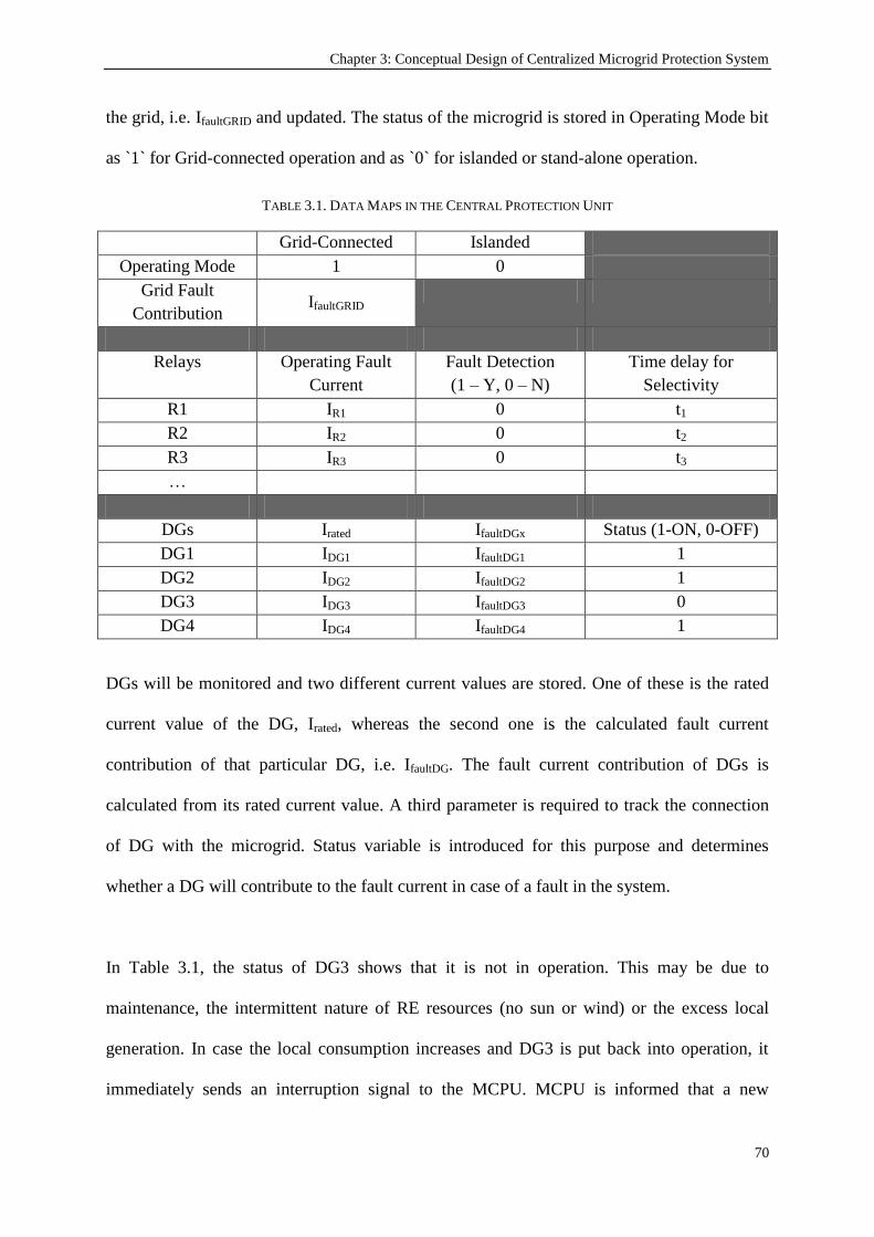
Chapter 3: Conceptual Design of Centralized Microgrid Protection System
70
the grid, i.e. IfaultGRID and updated. The status of the microgrid is stored in Operating Mode bit
as `1` for Grid-connected operation and as `0` for islanded or stand-alone operation.
TABLE 3.1. DATA MAPS IN THE CENTRAL PROTECTION UNIT
Grid-Connected Islanded
Operating Mode 1 0
Grid Fault
Contribution IfaultGRID
Relays Operating Fault
Current
Fault Detection
(1 – Y, 0 – N)
Time delay for
Selectivity
R1 IR1 0 t1
R2 IR2 0 t2
R3 IR3 0 t3
…
DGs Irated IfaultDGx Status (1-ON, 0-OFF)
DG1 IDG1 IfaultDG1 1
DG2 IDG2 IfaultDG2 1
DG3 IDG3 IfaultDG3 0
DG4 IDG4 IfaultDG4 1
DGs will be monitored and two different current values are stored. One of these is the rated
current value of the DG, Irated, whereas the second one is the calculated fault current
contribution of that particular DG, i.e. IfaultDG. The fault current contribution of DGs is
calculated from its rated current value. A third parameter is required to track the connection
of DG with the microgrid. Status variable is introduced for this purpose and determines
whether a DG will contribute to the fault current in case of a fault in the system.
In Table 3.1, the status of DG3 shows that it is not in operation. This may be due to
maintenance, the intermittent nature of RE resources (no sun or wind) or the excess local
generation. In case the local consumption increases and DG3 is put back into operation, it
immediately sends an interruption signal to the MCPU. MCPU is informed that a new

Chapter 3: Conceptual Design of Centralized Microgrid Protection System
71
generator with separate fault current contribution has been connected to the network and thus,
needs to be taken into account. The new fault current contribution IfaultDG3 is updated in the
relay operating currents data. Similarly, if DG2 is shut down for a certain reason, it then
reports to the central unit that it is no-longer in operation and will not contribute to any fault
in the network. Its status bit will then be changed to 0 and new fault current calculations will
be performed without IfaultDG2. In this fashion, individual contributions of DGs are handled
and the aggregate affect thereof is reflected on the relay settings to adjust them for the
changing conditions of the microgrid.
Three parameters are used for relays in the MCPU. `Irelay` is the operating current of the relay
which is used to program the relays, `fault detection bit` shows the fault detection status of
the relay and `time delay for selectivity` indicates the time delays assigned to each particular
relay for proper selective operation.
For a particular relay, the operating fault current (i.e. the current level that causes the relay to
trip) is calculated as shown in (3.1).
(3.1)
where m is the total number of DGs in the microgrid,
ki is the impact factor of ith distributed generator on the fault current of the relay,
IfaultGRID, IfaultDGi and StatusDGi are as described above.
If the microgrid is operating in islanded mode, then the grid‟s fault contribution will be
multiplied with the „Operating Mode=0‟ bit which will be equal to 0. Likewise, the fault
contribution of a DG which is not in operation will be annulled by its status `StatusDGi` bit.

Chapter 3: Conceptual Design of Centralized Microgrid Protection System
72
In small microgrids, it may be assumed that the distances between components are small and
the fault contribution of a certain distributed generator will be the same for all parts of the
microgrid. In this case, the equation may be simplified by taking k = 1, i.e. it is assumed that
the fault current contribution of any particular DG is constant for all relays in the network. In
larger or more complex networks this may not be the case and a combination of various fault
current contributions along with their impact coefficients might be required to be taken into
account. This phenomenon is studied in detail in Chapter 5.
Determination of a distributed generator‟s fault contribution can be performed in various
ways. It can be determined by means of simulation studies which require the modeling of the
microgrid. However, an easier approach might be adopted on the grounds that most of the
DGs need PE interface for grid connection. It is well known that PE interfaces do not supply
fault currents as rotating machines do. Their contribution can then be approximated to
IfaultDG=1.2 * IratedDG [78, 80, 153]. Should this approach be implemented, new DG
deployments can be made without making fundamental changes in the protection system.
They can be treated as plug-and-play devices once their rated currents and fault contributions
are reported to the MCPU. MCPU can track their status bit and perform calculations
according to the reported fault current contribution. Hence, the communication between a PE
interfaced DG and the MCPU could be limited to only status updates.
The MCPU uses an interrupt based algorithm shown in Figure 3.7. Once a new connection or
disconnection occurs in the network, an interrupt is received by the MCPU and new fault
currents are calculated based on the current situation of the network. Then, new operating
conditions are updated in relays for adaptive protection. It is worthy to note that once the
MCPU performs these tasks and re-programs the operating conditions of the relays, they

Chapter 3: Conceptual Design of Centralized Microgrid Protection System
73
operate independently to open the connections through CBs without the need for further
communication. Once the current flowing over the relay exceeds the latest operating current
received from MCPU, the relay opens the connection with CB and sends a signal back to
MCPU in order to report the fault and set the fault detection bit.
Figure 3.7. Interrupt-based Protection Algorithm
Once there is a fault in the system, the relays on the fault path shall experience the fault
current. Each relay shall wait for its own time delay to expire after the detection of the fault.
These time delays are set to ensure proper selectivity in the system and stored in MCPU as
well as in the relays. Obviously central relays such as R1 and R2 have larger time delays than
those of located in branches such as R4 and R8. The system shown in Figure 3.6 does not
require rearrangement of time delays for different operating conditions due to the structure of
the microgrid. In a more complex system, this might be very well required. In this case, with

Chapter 3: Conceptual Design of Centralized Microgrid Protection System
74
each interrupt signal MCPU does not only calculate the operating currents of the relays but
also determines the selectivity hierarchy and calculates new time delay settings required.
Then, these two parameters are updated in the relays. New Irelay value ensures that relays
detect the fault currents accurately while new time delay setting trelay ensures that proper
selectivity procedures are followed in case of a fault. Selectivity hierarchy detection is
discussed in detail in Chapter 4 while time delay calculations are explained in Chapter 4 as
well as Chapter 5.
3.4. Power Networks with Fault Current Limiters(FCL)
As mentioned earlier, DGs with inverter interface do not supply as much fault currents as the
rotating machines. This contribution is not enough to operate CBs or fuses. Conversely, being
composed of solid state devices, inverters cannot operate under fault conditions for long time.
Disconnection of inverters under fault conditions is not desirable to sustain a certain level of
power quality in the microgrid during and just after the fault conditions [157]. Considering
the increasing popularity of DGs, it is certain that large deployments will take place in the
near future. In this case, the fault current build up might reach a value higher than the ratings
of the protection devices. The existing switchgear has certain capacities, and the extra fault
current contributions of the newly added DGs might hinder the overall protection scheme.
Since changing every single protection device in a microgrid/network will be very expensive
and unfeasible, again, current limitation might be necessary [158].
An ideal FCL should have some basic properties for proper operation [159]. A FCL is
required to have zero impedance under normal operation and large impedance under fault
conditions. It should detect the fault current rapidly and initiate limiting action before fault
current builds up to its prospective value. It should be able to withstand the fault current until
fault is detected and cleared in order to sustain a certain level of power quality. It should

Chapter 3: Conceptual Design of Centralized Microgrid Protection System
75
operate in a fail safe manner; have a long maintenance interval and life time so that the
investment can be justified. For easy and wide-spread installation, it should be compact and
cost-effective. It is also anticipated that in the future FCLs might be coupled with CBs or
DGs and sold as an integral part of the overall equipment [159].
Different types of FCL embodiments exist in the literature which, include solid state FCL
topologies, superconducting fault current limiters (SCFCL) and modified inverter control
loops with FCL component. Figure 3.8 shows the solid state FCL topology proposed in [158].
It is comprised of a mechanical series switch, a current limiting inductor, a voltage limiting
element and a fast solid-state switch pair. The Gate Turn Off (GTO) thyristors are connected
in parallel with the current limiting impedance. This configuration is accompanied with a
control system that monitors the system and upon detecting a fault sends turn-off signal to
GTO thyristors. Now the connection is realized through current limiting impedance and the
buildup of the fault current is limited. The voltage limiting element, i.e. the MOV, is in
charge of preventing the overvoltage which may arise upon sudden current interruption.
Figure 3.8. Solid state FCL topology in [158].
Figures 3.9 and 3.10 show the inverter interface which connects DG to the grid and the
additional loop employed in inverter control to realize FCL in [157]. It is important to note
that these topologies require output inductors to control the output current. The control loop
shown in Figure 3.9 monitors the output voltage and when a fault is detected it arranges

Chapter 3: Conceptual Design of Centralized Microgrid Protection System
76
inverter trigger signals so that inductor currents are set to a predetermined maximum value
(Imax).
Figure 3.9. The inverter interface used in [157].
Figure 3.10. Fault current limitation algorithm for the topology in Figure 3.9 [157].
Current limitation in inverter based FCLs can be achieved in three different ways [160].
Firstly, instantaneous limits in the natural reference frame can be forced which results in
clipping and distorted waveforms. Alternatively, instantaneous limits in the synchronously
rotating reference frame might be forced. This freezes inductor current reference direct and
quadrature components when the inductor current exceeds a threshold value. Thirdly, once

Chapter 3: Conceptual Design of Centralized Microgrid Protection System
77
the inductor current exceeds a threshold a constant predetermined inductor fault current is
supplied as shown in Figure 3.11 [160].
Figure 3.11. Fault current limitation curves for inverter topology [160].
Below the threshold value, there is no control on inductor current, i.e. inverter output current.
Once the threshold current, ith, is passed, a predetermined fault current value, if is observed at
the output. This value is typically set to be twice as much the rated current. The dynamic
performance of the FCL is characterized by the difference of two time values. tf represents
the time of fault while td represents the instance when the fault is detected by the FCL and the
output current is fixed to predetermined if value.
3.5. Conceptual Design with Fault Current Limiter
The conceptual design can be adapted to accommodate DGs or networks with FCL
connection. As a matter of fact, FCL connection is a special case of the system given above.
Here, the exact fault current contribution of each DG is known and not calculated.
When FCLs are utilized, the data map in the MCPU can be updated as shown in Table 3.2.
The only difference is with the DG parameters where IfaultDG is directly recorded rather than
being calculated with the help of k coefficient and the rated current, Irated.

Chapter 3: Conceptual Design of Centralized Microgrid Protection System
78
It is assumed that all DGs are interfaced with an inverter that has FCL ability which limits the
DG output current to a predetermined IfaultDGx value. Since fault currents are known exactly
rather than calculated or approximated, the performance of the entire protection system will
be more accurate and reliable.
The MCPU continuously monitors the statuses of all DGs in a synchronized manner by
communicating with them using a Publish/Subscribe peer-to-peer messaging (similar to IEC
61850‟s GOOSE [161]) system. The MCPU therefore receives status report from all DGs
and records their status as ON/OFF. If a DG disconnects at any time for example, the new
fault current levels are re-calculated by considering the fault current contribution (IfaultDGx) of
that particular DG. In this way, the system is ready for any fault condition before any fault,
actually, occurs. The operation of the system through communication and calculation is
identical with the generic system given above.
TABLE 3.2. DATA MAPS IN THE CENTRAL PROTECTION UNIT
Grid-Connected Islanded
Operating Mode 1 0
Grid Fault
Contribution IfaultGRID
Relays Operating Fault
Current
Fault Detection
(1 – Y, 0 – N)
Time delay for
Selectivity
R1 IR1 0 t1
R2 IR2 0 t2
R3 IR3 0 t3
…
DGs IfaultDGx Status (1-ON, 0-OFF)
DG1 IfaultDG1 1
DG2 IfaultDG2 1
DG3 IfaultDG3 0
Alternatively, the use of FCLs makes it possible to simplify this system further. Since fault
contribution of each DG is constant, it may be reported to the MCPU before DG‟s

Chapter 3: Conceptual Design of Centralized Microgrid Protection System
79
deployment and the communication line for that might be omitted. Furthermore, the status of
a DG can be monitored through the status of its respective relay (e.g. R3 for DG1, R5 for
DG2 etc.). For example, if R3 is connected then it means DG1 is in operation and in case of a
fault IfaultDG1 should be taken into account and if R3 is open it implies DG1 is OFF and no
fault current is in question. In this case, relay‟s status is sufficient and the communication
lines from the MCPU to DGs can be eliminated altogether. In such a case, fault current
contributions of DGs will be stored in the MCPU before deployment and updated in rare
cases of modification. In this way, not only the fault currents of DGs will be known precisely
but also the burden of installing expensive and complex communication lines to each DG, the
dark and light blue lines in Figure 3.6, can be eliminated. This simplification has effects on
the MCPU, as the area marked with dashed frames will be eliminated if DG communication
is omitted. Thus, the data map in MCPU will include relay parameters and static DG
parameters which only require local storage. Worthy to note, though, this simplification does
not include intermittent DGs such as Wind turbines or PVs. These DGs may be connected to
the grid but may not generate any power due to intermittent nature of their sources, i.e. the
wind and the sun. On the other hand, diesel generators, fuel cells and other DGs that have
constant power output can be incorporated to this simplified protection scheme.
Under these new conditions, for a particular relay, the operating fault current (the current level
that causes the relay to trip) is calculated as in (3.2):
(3.2)
where m is the total number of DGs in the microgrid,
IfaultGRID, IfaultDGi and StatusDGi are as described above.

Chapter 3: Conceptual Design of Centralized Microgrid Protection System
80
The MCPU uses a simple algorithm shown in Figure 3.12. The status of R1 has been given a
special consideration since it imposes the operating mode and grid fault contribution.
Figure 3.12. Protection Algorithm employed in MCPU for FCLs.
This flow chart is similar to the one given in Figure 3.7 with a fundamental difference. Unlike
the algorithm in Figure 3.7, this flow chart only follows the connections of relays. This is
thanks to the unique feature of FCL interfaced DGs where the whole monitoring can be
realized over relays. In this manner, management and communication processes have been
simplified. Here, the operating condition of the microgrid is checked over R1 and the fault
contribution of the grid is taken into account. Then, the relays for DG connections are
checked to update their fault current contributions. Finally, the new operating current
conditions are updated in the relays. In case of a fault in the network, relays operate
independently and follow selective protection procedures, as discussed above.

Chapter 3: Conceptual Design of Centralized Microgrid Protection System
81
3.6. Conclusion
The studies on microgrids will aid in the development of secure, reliable, and stable real-life
networks with greater penetrations of RE sources. This chapter has presented a new
protection scheme for microgrids with high DG penetration. An MCPU is utilized to monitor
all entities inside the microgrid and new operating conditions are calculated for every change
experienced in the microgrid. The developed system considers two events as crucial changes:
microgrid‟s connection/disconnection (i.e. islanding) from the grid and a DG‟s
connection/disconnection from the microgrid. The MCPU is used to perform fault current
contribution calculations by considering the rated currents and fault contribution coefficients
`k` of DGs. After being updated with these operating conditions, relay make decisions locally
depending on the local measurements. This makes the system more robust and reliable since
continuous communication is not needed in the decision making process.
The system is very versatile and can be developed to suit more specific purposes or meet
different purposes. It can be extended to suit much larger and more complex microgrids.
Furthermore, it can be adapted to accommodate different grid components such as FCLs.
Limited fault current helps anticipate fault conditions and protection system is programmed
accordingly. Communication lines and MCPU can be simplified thanks to the constant and
predetermined fault current contribution of DGs. Since the exact fault current contribution is
known, this protection system is more reliable than the systems which predict or approximate
fault conditions. DGs with FCL can be deployed merely by creating an additional record in
MCPU. Relative fault current and the relay which is responsible for its connection are
recorded.

Chapter 3: Conceptual Design of Centralized Microgrid Protection System
82
Specifically, the system is designed to be generic and may serve for plug-and-play purposes.
Special attention must be paid to the communication protocol utilized for the communication
of data within the system and a standard packet-type for the relay and distributed generator
communication can be developed. If each DG unit is equipped with a simple communication
device to report its status, rated current and fault contribution, then a universal concept of DG
connection can be achieved. This may prove useful for the implementation of plug and play
concept in microgrids.
This flexible yet strong conceptual design has been reinforced with various aspects of this
research. The automated microgrid structure detection and its impact on selectivity will be
discussed in Chapter 4. The specific details of the relay parameter assignments, i.e. fault
current and time delay, will be discussed in Chapter 5. Chapter 6 presents the standard
communication framework developed in accordance with IEC 61850 to universalize this
conceptual design. Chapter 7 provides the results of the simulation works undertaken to
investigate behavior of microgrids under different conditions. The conceptual design presented
in this chapter has been developed based on these behaviors. Finally, Chapter 8 extends this
design further, and shows how this system can be used to support other protection systems
where they are insufficient. The eventual system has the ability to address varying challenges
of new generation microgrids.

Chapter 4: Object Oriented Modeling of Microgrids and Automated Structure Detection
83
Chapter 4
Object Oriented Modeling of Microgrids and Automated
Structure Detection
Publications pertaining to this chapter:
1) Taha Selim Ustun, Cagil Ozansoy, Aladin Zayegh, "Implementation of Dijkstra’s Algorithm in a
Dynamic Microgrid for Relay Hierarchy Detection," in the Proceedings of Smart Grid Communications
(SmartGridComm), 2011 IEEE International Conference on , vol., no., pp.481-486, 17-20 Oct. 2011.
2) Taha Selim Ustun, Cagil Ozansoy, Aladin Zayegh, "Using Object Oriented Data Structures for
Dynamic Communication and Control in Electrical Networks," in the Proceedings of the Twenty-fifth
Canadian Conference on Electrical and Computer Engineering (CCECE), Canada, 29April – 2 May
2012.
4.1. Introduction
Microgrids have very dynamic structures and automated control and protection of microgrids
would only be possible when the microgrid structure is continuously monitored. This chapter
details the ideas and concepts developed to enable such a process. Object Oriented (OO)
models have first been developed that allow information on various elements of a microgrid
systems (power system networks in general) to be defined. The use of the graph theory
concept for modeling the structure of the microgrid is then discussed and finally the use of a
famous Computer Science algorithm for relay hierarchy detection is explained.

Chapter 4: Object Oriented Modeling of Microgrids and Automated Structure Detection
84
It is known that microgrids have dynamic structures which change very often. The following
may be counted among the reasons for the changes in the microgrid structure [146]:
New DG or load deployments
Islanding of the system
Fault conditions
Reconfiguration of the structure for reasons such as maintenance
This dynamic behavior of microgrids is a major protection challenge since the conventional
selectivity methods assume a fixed network structure and a predetermined relay hierarchy
[108]. Whenever restructuring occurs, the selective levels assigned prior to that become
erroneous. For a proper operation, the selective levels of relays should follow the changing
conditions of the network. Whenever a structure variation takes place in a microgrid, new
relay hierarchy should be extracted and corresponding settings including time delays should
be determined before updating these settings within the relays via communication lines [109,
110]. It is essential that this process is performed automatically so that the processing time is
minimal and there is no interruption in power delivery. This requires an algorithm which will
determine the current structure of the system and yield the relay hierarchy at all branches of
the network.
There are some studies presented in the literature which emphasize on the importance of such
an adaptive selective operation such as in [162] and [73]. However, the prior discusses the
issue qualitatively without any technical details whereas the latter implements an algorithm
which includes a look-up table. The work presented in [162] touches upon the challenging
nature of relay hierarchy and selectivity concepts in microgrids. A communication-assisted
selectivity approach is explained in concept. However, the technical details of this approach,

Chapter 4: Object Oriented Modeling of Microgrids and Automated Structure Detection
85
its implementation in microgrids with different set of components are not discussed. On the
other hand, the research presented in [73] provides a robust system for microgrid protection.
However, it uses a look-up table which lists all the cases that may exist in the microgrid
under consideration. This is a large set-back because it requires the knowledge of all possible
microgrid configurations beforehand, plus human input for the preparation of this look-up
table and finally it requires that the microgrid should always match one of the predetermined
structures. Moreover, any kind of a new deployment, which is very common to microgrids,
requires that the whole selectivity table should be re-written.
In order to address all of the above-mentioned challenges, the developed protection system
shall be equipped with an automated operation capability that determines the structure of the
system and yields the relay hierarch. This chapter details the work carried out as part of this
research to address this development need. Firstly, the novel representation of power
networks with OO models is explained. Then, the challenging nature of microgrid structure
variations is given. OO models have thereby been developed to handle the dynamic and
changing nature of microgrids. Accordingly, a microgrid system is modeled based on graph
theory where the components are represented as nodes. Later, Dijkstra‟s algorithm, which is
famous for shortest-path calculation purposes, is run over the microgrid to determine the
relay hierarchy at any point in time. In this manner, regardless of the dynamic changes
occurring in the system, the hierarchy of the network components can be extracted. The
implemented algorithm not only ensures proper selective operation under fault conditions but
also facilitates the introduction of new connections and new devices to the system. Since the
relay hierarchy is detected automatically, even with new connections, this algorithm serves
for plug-and-play concepts in electrical networks.

Chapter 4: Object Oriented Modeling of Microgrids and Automated Structure Detection
86
4.2. Object Oriented (OO) Representation of Power Networks
As mentioned in the previous section, the varying structure of the microgrid requires a
process which can represent information about the network in a computer environment and
monitor the changes occurring therein. When the structure of the system is fully known to the
central controller, the operation settings of protective devices, generators, loads and other
auxiliaries can be calculated in the central microgrid controller and updated into relative
devices [146].
When all the connected devices are recognized as nodes and their connection/disconnection is
followed in the modeling system, then the microgrid can be defined in accordance with
different methods such as the graph theory [163]. Thus some of the issues listed in literature
on microgrid management and protection can be tackled with the well-known procedures of
those methods [164] [165].
Over the years, international standards such as IEC 61850 have defined many OO data and
communication models for power system networks especially for substations. However, these
standards are continuously evolving with new additions and amendments. There is a
significant need for a data model to represent the information with regards to the various
node points such as bus bars along the distribution network. Such a data model would allow
valuable information such as load profile or generation capacity connected to a particular
point within the network to be communicated across to control equipment.

Chapter 4: Object Oriented Modeling of Microgrids and Automated Structure Detection
87
Figure 4.1. Electrical Network Node and 4 specific instances of the model
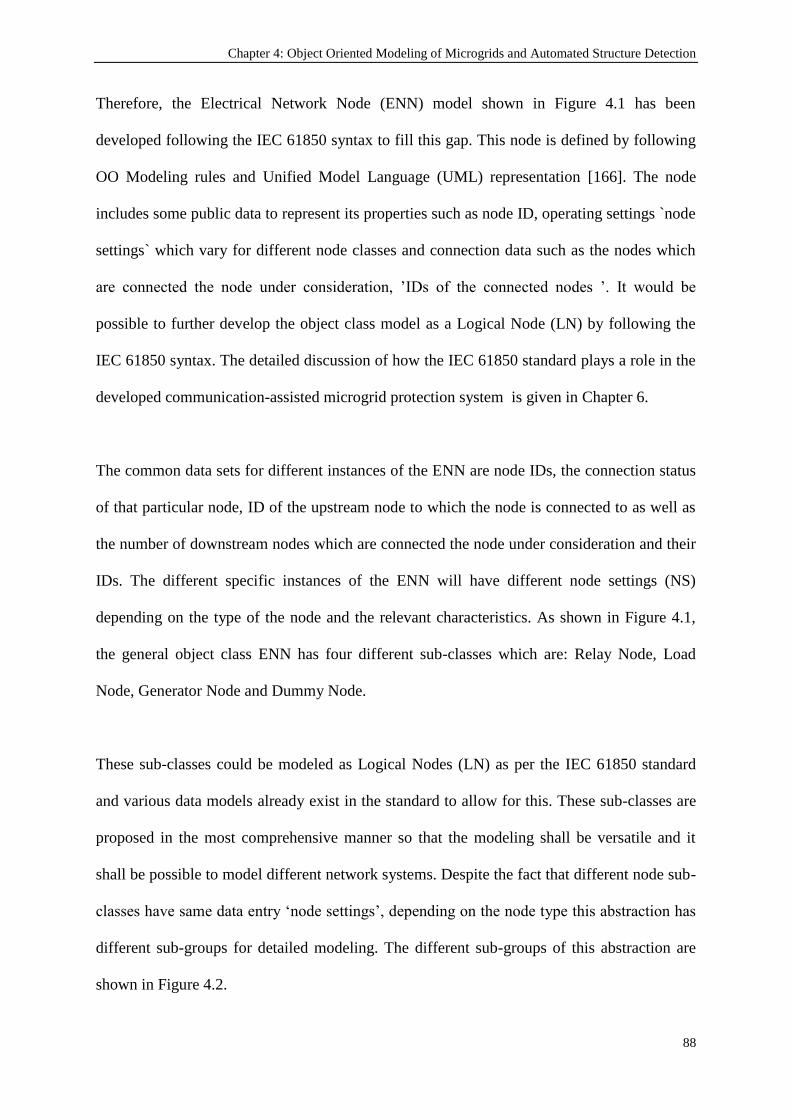
Chapter 4: Object Oriented Modeling of Microgrids and Automated Structure Detection
88
Therefore, the Electrical Network Node (ENN) model shown in Figure 4.1 has been
developed following the IEC 61850 syntax to fill this gap. This node is defined by following
OO Modeling rules and Unified Model Language (UML) representation [166]. The node
includes some public data to represent its properties such as node ID, operating settings `node
settings` which vary for different node classes and connection data such as the nodes which
are connected the node under consideration, ‟IDs of the connected nodes ‟. It would be
possible to further develop the object class model as a Logical Node (LN) by following the
IEC 61850 syntax. The detailed discussion of how the IEC 61850 standard plays a role in the
developed communication-assisted microgrid protection system is given in Chapter 6.
The common data sets for different instances of the ENN are node IDs, the connection status
of that particular node, ID of the upstream node to which the node is connected to as well as
the number of downstream nodes which are connected the node under consideration and their
IDs. The different specific instances of the ENN will have different node settings (NS)
depending on the type of the node and the relevant characteristics. As shown in Figure 4.1,
the general object class ENN has four different sub-classes which are: Relay Node, Load
Node, Generator Node and Dummy Node.
These sub-classes could be modeled as Logical Nodes (LN) as per the IEC 61850 standard
and various data models already exist in the standard to allow for this. These sub-classes are
proposed in the most comprehensive manner so that the modeling shall be versatile and it
shall be possible to model different network systems. Despite the fact that different node sub-
classes have same data entry „node settings‟, depending on the node type this abstraction has
different sub-groups for detailed modeling. The different sub-groups of this abstraction are
shown in Figure 4.2.

Chapter 4: Object Oriented Modeling of Microgrids and Automated Structure Detection
89
For instance, the relay node should have at least two attributes which represent the operation
settings of the relay. The first sub-group of attributes represents the details of a time-inverse
relay while the second sub-group of attributes is used to model instantaneous relays [88]. In
similar fashion the generators are categorized under two main headings such as bulk
generation and distributed generation. The former is required if the microgrid is connected to
a larger generation system while the latter is a vital element for distributed generators such as
diesel gen-sets, micro hydroelectric power plants (MHEPP) and other renewable energy
resources.
The modeling of loads is kept very simple and only two different sub-groups have been
proposed which differentiate between the rotating machine loads and resistive loads which
are hard-to-control and lightweight loads, respectively.
Figure 4.2. Abstraction of NS for different Node types handled by Update Settings Function

Chapter 4: Object Oriented Modeling of Microgrids and Automated Structure Detection
90
It is crucial to attain universal operation with these models where it shall be possible to model
same type of equipment from different manufacturers with the same node. For this purpose,
the detailed characteristics listed in node settings shall be acquired from an international
standard, such as IEC 61850 which is bound to have a significant impact on how electric
power systems are to be designed and built for many years to come [167].
Referring back to Figure 4.1, the ENN data model has five different services which are
needed to:
1. Get connected to another node,
2. Get disconnected from an already-connected node,
3. Receive the ID of a particular node for identification purposes,
4. Acquire the settings of a particular node for management purposes,
5. Update the current settings of the node with the new operation points stipulated by the
MCPU.
Among these nodes, the dummy node might be of particular interest. It, in fact, does not
represent a specific device but a common coupling point where different connections meet.
For example, the network shown in Figure 4.3 requires a dummy node to connect Circuit
Breaker 2 (CB2) to CB3 and CB4. Even if microgrid gets islanded, i.e. CB2 opens, CB3 and
CB4 will remain connected over the dummy node.
At any given instance, the new connection or disconnection of a device shall be represented
by these OO models with abstracted node setting groups.
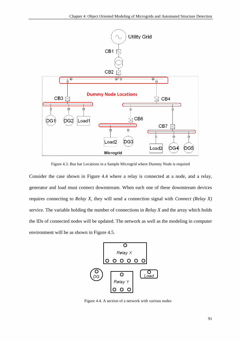
Chapter 4: Object Oriented Modeling of Microgrids and Automated Structure Detection
91
Figure 4.3. Bus bar Locations in a Sample Microgrid where Dummy Node is required
Consider the case shown in Figure 4.4 where a relay is connected at a node, and a relay,
generator and load must connect downstream. When each one of these downstream devices
requires connecting to Relay X, they will send a connection signal with Connect (Relay X)
service. The variable holding the number of connections in Relay X and the array which holds
the IDs of connected nodes will be updated. The network as well as the modeling in computer
environment will be as shown in Figure 4.5.
Figure 4.4. A section of a network with various nodes
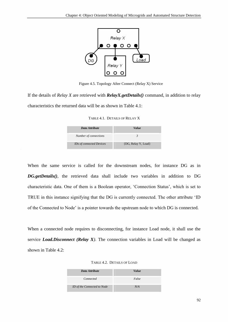
Chapter 4: Object Oriented Modeling of Microgrids and Automated Structure Detection
92
Figure 4.5. Topology After Connect (Relay X) Service
If the details of Relay X are retrieved with RelayX.getDetails() command, in addition to relay
characteristics the returned data will be as shown in Table 4.1:
TABLE 4.1. DETAILS OF RELAY X
Data Attribute Value
Number of connections 3
IDs of connected Devices {DG, Relay Y, Load}
a)
When the same service is called for the downstream nodes, for instance DG as in
DG.getDetails(), the retrieved data shall include two variables in addition to DG
characteristic data. One of them is a Boolean operator, „Connection Status‟, which is set to
TRUE in this instance signifying that the DG is currently connected. The other attribute „ID
of the Connected to Node‟ is a pointer towards the upstream node to which DG is connected.
When a connected node requires to disconnecting, for instance Load node, it shall use the
service Load.Disconnect (Relay X). The connection variables in Load will be changed as
shown in Table 4.2:
TABLE 4.2. DETAILS OF LOAD
Data Attribute Value
Connected False
ID of the Connected to Node N/A

Chapter 4: Object Oriented Modeling of Microgrids and Automated Structure Detection
93
While the related variables in Relay X will be updated as shown in Table 4.3:
TABLE 4.3. DETAILS OF RELAY X AFTER LOAD.DISCONNECT (RELAY X)
Data Attribute Value
Number of connections 2
IDs of connected Devices {DG, Relay Y}
Following this modeling procedure the changes occurring in the microgrid can be monitored
instantaneously and the relevant power management, protection or other adjustments can be
performed immediately. As it has been expressed before, dynamically following the changes
occurring in the microgrids and extracting the resultant microgrid topology is extremely
important. The next section elaborates upon this importance from microgrid protection
perspective and reveals the approach developed for its achievement.
4.3. Relay Hierarchy and Selectivity Issues
Selectivity is a well-known protection concept which means isolating the fault with the
nearest relay in an effort to minimize its effect on the rest of the system (grid) [168, 169].
This requires that in case of a fault, the relays should react according to a certain hierarchy. In
conventional protection systems designed for passive networks, the relays which are
downstream and closer to the fault point are required to operate first. However, if the fault
current is very large and downstream relays are not capable of interrupting it, then other
relays with larger capacities are expected to operate and isolate the fault.
That being said, implementation of selectivity is not that straightforward with the
introduction of DGs. The very concepts of downstream and upstream relays are prone to
change according to the status of the microgrid. The operating mode, i.e. grid-connected or

Chapter 4: Object Oriented Modeling of Microgrids and Automated Structure Detection
94
islanded-mode, changing network structure with alternative paths and new deployments are
some of the factors that would alter the selectivity parameters.
Consider the system shown in Figure 4.6. In this network, all branches have generation and
load, and various alternative network structures can be formed through the combination of
CB connections.
Figure 4.6. A sample microgrid
As first case, assume that the circuit breakers CB1, CB2, CB3, CB4, CB6 and CB7 are closed
whereas CB5 remains open, as shown below in Figure 4.7. When a fault occurs at the
terminals of Load 2, then the most downstream relay will be Load 2‟s own relay (represented
by the little box) and selectivity implies that it should interrupt the connection. If Load 2‟s
relay fails to achieve that in a predetermined time (delay), then the proper sequence for the
selective operation should be CB6, CB4 and finally CB2. In similar fashion, should a fault
occur at the terminals of Load 3, the proper selective operation requires the following
sequence: Load 3‟s relay, CB7, CB4 and CB2.

Chapter 4: Object Oriented Modeling of Microgrids and Automated Structure Detection
95
Figure 4.7. The network structure when CB5 is open and CB4 is closed (1st Case)
If CB4 is disconnected for any reason, for example maintenance or breakdown, in order to
keep the integrity of the network, CB5 closes. The line between Load 1 and Load 2 (protected
by CB5) has therefore been added to form a loop structure when necessary and protect the
microgrid against contingencies and failures. When CB5 loses, the structure change from
case 1 to case 2 is shown in Figure 4.8.
Figure 4.8.The Network structure when CB5 closes and CB4 opens (2nd
Case)

Chapter 4: Object Oriented Modeling of Microgrids and Automated Structure Detection
96
As shown, now in Figure 4.8, there is only one branch for the power flow instead of two. For
this new microgrid structure all selective levels, time steps and time delay calculations shall
be repeated. Following the same examples should a fault occur at Load 2 or Load 3, the
proper relay hierarchies are; Load2‟s relay, CB5, CB3, CB2 and Load 3‟s relay, CB6, CB5,
CB3, CB2, respectively.
One exceptional case arises when a fault occurs at upper levels of the microgrid. In this case,
fault should be isolated by the closest relay at the higher level and this requires the inversion
of the hierarchy structure. For example, if a fault occurs outside the microgrid, i.e. in the
utility grid, the microgrid should be isolated from the system by opening CB2. In this case,
the interfacing relay CB2, which is at the top of the selectivity pyramid, is required to operate
first. This can be managed by detecting the reverse flow of the fault current and assigning
two different time delays to the relays, one for upstream faults and the other for downstream
faults.
The above mentioned factors require that the selectivity hierarchy of the relays should be
dynamic and updated frequently. An algorithm should be employed which determines the
network structure whenever the status of a critical relay is changed. A critical relay refers to a
relay the status of which changes the structure of the network. Following this definition
relays of CB2, CB3, CB4, CB5 and CB6 are all critical relays whereas Load 2‟s relay, DG1‟s
relay are non-critical relays.
After determining the microgrid structure and its relay hierarchy, suitable time delays can be
appointed easily. Let tmax be the maximum time length allowed by the grid code before the
fault is cleared in the system. This value is divided into the number of selective levels, n, in
the relay hierarchy and the base time delay is found as in (4.1).
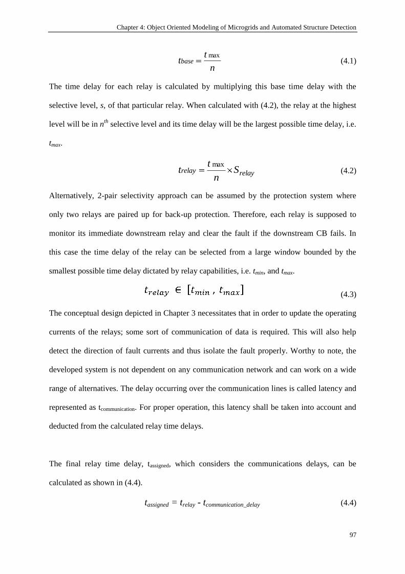
Chapter 4: Object Oriented Modeling of Microgrids and Automated Structure Detection
97
n
ttbase
max (4.1)
The time delay for each relay is calculated by multiplying this base time delay with the
selective level, s, of that particular relay. When calculated with (4.2), the relay at the highest
level will be in nth
selective level and its time delay will be the largest possible time delay, i.e.
tmax.
relayrelay Sn
tt
max (4.2)
Alternatively, 2-pair selectivity approach can be assumed by the protection system where
only two relays are paired up for back-up protection. Therefore, each relay is supposed to
monitor its immediate downstream relay and clear the fault if the downstream CB fails. In
this case the time delay of the relay can be selected from a large window bounded by the
smallest possible time delay dictated by relay capabilities, i.e. tmin, and tmax.
(4.3)
The conceptual design depicted in Chapter 3 necessitates that in order to update the operating
currents of the relays; some sort of communication of data is required. This will also help
detect the direction of fault currents and thus isolate the fault properly. Worthy to note, the
developed system is not dependent on any communication network and can work on a wide
range of alternatives. The delay occurring over the communication lines is called latency and
represented as tcommunication. For proper operation, this latency shall be taken into account and
deducted from the calculated relay time delays.
The final relay time delay, tassigned, which considers the communications delays, can be
calculated as shown in (4.4).
tassigned = trelay - tcommunication_delay (4.4)

Chapter 4: Object Oriented Modeling of Microgrids and Automated Structure Detection
98
4.4. Dijkstra’s Algorithm for Automated Structure Detection
Dijkstra‟s algorithm [170, 171] is a graph search algorithm that solves the shortest path
problem from a single source to many destinations [163]. It can be implemented on a graph
where a node (or vertex) may have more than one connection. The algorithm employs a step
by step approach and finds the shortest path to a neighbor vertex and then moves on to its
neighbors. For a better understanding, consider the graph given in Figure 4.9.
Figure 4.9. A sample graph for shortest path problem
If it is desired to find the shortest path from node (a) to all other nodes, the algorithm runs as
follows;
1. Assign all nodes infinite distance and mark all nodes unvisited
2. Mark the initial node (i.e. node a) as current
3. For current node, calculate the distance to all neighbors. If it is shorter than the
previously recorded distance update it.
4. If all neighbors are visited, mark current node as visited.
5. Halt, if all nodes are visited. If not, assign the nearest unvisited node as the current
node and loop to Step 3.
Figure 4.10 shows the implementation of the first 3-steps given above for `node a`. Node (a)
is assigned as the current node and all the distances to the other nodes are set to be unknown.
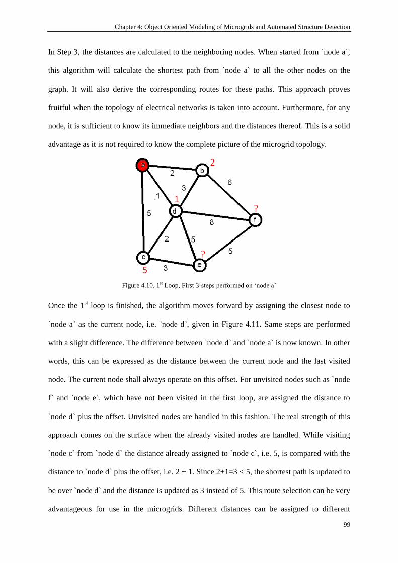
Chapter 4: Object Oriented Modeling of Microgrids and Automated Structure Detection
99
In Step 3, the distances are calculated to the neighboring nodes. When started from `node a`,
this algorithm will calculate the shortest path from `node a` to all the other nodes on the
graph. It will also derive the corresponding routes for these paths. This approach proves
fruitful when the topology of electrical networks is taken into account. Furthermore, for any
node, it is sufficient to know its immediate neighbors and the distances thereof. This is a solid
advantage as it is not required to know the complete picture of the microgrid topology.
Figure 4.10. 1st Loop, First 3-steps performed on „node a‟
Once the 1st loop is finished, the algorithm moves forward by assigning the closest node to
`node a` as the current node, i.e. `node d`, given in Figure 4.11. Same steps are performed
with a slight difference. The difference between `node d` and `node a` is now known. In other
words, this can be expressed as the distance between the current node and the last visited
node. The current node shall always operate on this offset. For unvisited nodes such as `node
f` and `node e`, which have not been visited in the first loop, are assigned the distance to
`node d` plus the offset. Unvisited nodes are handled in this fashion. The real strength of this
approach comes on the surface when the already visited nodes are handled. While visiting
`node c` from `node d` the distance already assigned to `node c`, i.e. 5, is compared with the
distance to `node d` plus the offset, i.e. 2 + 1. Since 2+1=3 < 5, the shortest path is updated to
be over `node d` and the distance is updated as 3 instead of 5. This route selection can be very
advantageous for use in the microgrids. Different distances can be assigned to different

Chapter 4: Object Oriented Modeling of Microgrids and Automated Structure Detection
100
equipment to represent the preference of use. In this fashion, distance may represent less
preference while the shortest path may represent the preference of use.
Figure 4.11. 2nd
Loop, First 3-steps performed on „node d‟
In the third loop, illustrated in Figure 4.12, another alternative route is discovered through
`node b`. When calculating the distance to `node f` the algorithm compares the distance over
`node d`, i.e. 1+8, with the distance over `node b`, i.e. 2+6. Since the latter is shorter than the
former, the distance of `node f` to `node a` has been updated as 8 in place of 9.
Figure 4.12. 3rd
Loop, First 3-steps performed for node b
To sum up, when the algorithm is run, it will start from "node a" and visit every node while
keeping track of the shortest path to get to that particular node. The algorithm shall halt when
all the nodes have been visited. As a result it will yield a table similar to Table 4.4.

Chapter 4: Object Oriented Modeling of Microgrids and Automated Structure Detection
101
TABLE 4.4. SHORTEST PATH FROM “NODE A”
Node Distance from “node a” Path
b 2 a-b
c 3 a-d-c
d 1 a-d
e 6 a-d-e f 8 a-b-f
As Table 4.4 shows, the algorithm finds that the shortest path to node c is an indirect path
over node d. The most important feature of this algorithm is when run once; it determines the
shortest distances and the corresponding paths to all nodes.
In order to be able to implement Dijkstra‟s algorithm, the microgrid should be represented as
a graph similar to the one shown in Figure 4.13. This is the graph representation of case 1
given earlier in Figure 4.7. The components have been represented as nodes, or vertexes,
while the connections have been represented as edges. This requires storage of network data
in an array or a linked list. Also the connections between the DGs, CBs and Loads should
also be stored in a matrix or linked list structure.
For real time response of the proposed technique, the real time data should be updated when a
node disconnects from the system or an edge disappears and an alternative edge is connected.
Such a change is depicted in Figure 4.14 where there are some connection changes as
compared to Figure 4.13. All these actions necessitate continuous monitoring of the
microgrid and utilization of communication lines between the nodes. This should not be
considered as a drawback, since such a system is already needed for smartgrids [172].
Furthermore, most of new generation microgrid protection systems incorporate a central
protection unit and communication lines as in [55, 73, 94].

Chapter 4: Object Oriented Modeling of Microgrids and Automated Structure Detection
102
Figure 4.13. Modeling of microgrid in Case 1 according to graph theory
Figure 4.14. Modeling of microgrid in Case 2 according to graph theory
In this research, selectivity application shall be studied as the case study. It must be noted that
the proposed method can also be used for power flow, load sharing and/or generation
planning purposes. For the proper application of selectivity, the main goal is to determine the
relay hierarchy. It is evident that, there is only one path between the point of origin, i.e. CB2,
and the destinations, i.e. all leaf nodes such as DG1, DG2, Load1, and Load2. This eliminates

Chapter 4: Object Oriented Modeling of Microgrids and Automated Structure Detection
103
the effect of distance and simplifies the existing problem to a path finding problem. In other
words, Dijkstra‟s algorithm will be used to find the paths between CB2 and leaf nodes and
identify the relay hierarchy.
In these graphs, all the distances are marked as one, since the shortness of the path is of no
concern. Nevertheless, there is another reason for using unit distances as it has a usage for
selectivity purposes. The distance yields number of the selective levels, n, between the origin
and the destination. If the leaf nodes are not assigned any time delay (meaning that they will
react immediately in case of a fault) the base time delay is calculated based on the parameter
n. Alternatively, if it is desirable to assign time delays for the relays of the leaf nodes then the
calculations will be based on value “n+1”. These calculations and the assignments of the
parameters will be discussed in Chapter 5, Parameter Assignment.
For the implementation of Dijkstra‟s algorithm on these graph representations, a C#
implementation provided in [173] is used. In this simplistic software, the nodes are placed on
the field and the necessary connections are added between the nodes. The distance of the path
is represented by the cost variable. As mentioned above, all distances are set to 1 for various
reasons.
When the graph is prepared, the software is used to select the origin and the destination
nodes. When the algorithm is run on the software, the shortest path is highlighted and the
details of the route are given in terms of the nodes it passes through. It is also possible to save
and load a particular graph in the software.

Chapter 4: Object Oriented Modeling of Microgrids and Automated Structure Detection
104
Firstly, the algorithm is run to find the shortest path (i.e. the only path in our case) between
CB2 and DG4 for Case 1. Figure 4.15 shows that the path is successfully highlighted on the
graph and the proper hierarchy is shown in `Report` area.
Figure 4.15. Dijkstra‟s Algorithm run for case 1, Path from CB2 to DG4
In order to change from Case 1 to Case 2 following services are executed to perform required
connections/disconnections:
Relay4.Disconnect(Relay2)
Relay6.Disconnect(Relay4)
Relay7.Disconnect(Relay4)
Relay5.Connect(Relay3)
Relay6.Connect(Relay5)
Relay7.Connect(Relay6)
It is observed that while using Dijkstra‟s algorithm, OO models developed earlier are utilized.
The services included in these models are also executed to reflect the changes occurring on
the electrical network. As shown above, the OO models and services of Relays are utilized to
represent the electrical network in virtual world. In this manner, OO modeling developed for
microgrids facilitate the use of Dijkstra‟s Algorithm for automated structure detection
purposes.

Chapter 4: Object Oriented Modeling of Microgrids and Automated Structure Detection
105
The algorithm is executed again to find the path between CB2 and DG4. As shown in Figure
4.16, the path is successfully found without a centralized monitoring for grid structure.
Figure 4.16. Dijkstra‟s Algorithm run for case 2, after grid re-configuration, Path from CB2 to DG4
The shortest paths and the distances obtained for both of the cases are given in Table 4.5.
TABLE 4.5. THE PATH FROM “CIRCUIT BREAKER 2”
Case 1 Case 2
Node Dist Path Dist Path
CB3 1 CB2-CB3 1 CB2-CB3
CB4 1 CB2-CB4 - -
*DG1 2 CB2-CB3-DG1 2 CB2-CB3-DG1
*DG2 2 CB2-CB3-DG2 2 CB2-CB3-DG2
*Load1 2 CB2-CB3-Load1 2 CB2-CB3-Load1
CB5 - - 2 CB2-CB3-CB5
CB6 2 CB2-CB4-CB6 3 CB2-CB3-CB5-CB6
CB7 2 CB2-CB4-CB7 4 CB2-CB3-CB5-CB6-CB7
*DG3 3 CB2-CB4-CB6-DG3 4 CB2-CB3-CB5-CB6-DG3
*Load2 3 CB2-CB4-CB6-Load2 4 CB2-CB3-CB5-CB6-Load2
*DG4 3 CB2-CB4-CB7-DG4 5 CB2-CB3-CB5-CB6-CB7-DG4
*DG5 3 CB2-CB4-CB7-DG5 5 CB2-CB3-CB5-CB6-CB7-DG5
*Load3 3 CB2-CB4-CB7-Load3 5 CB2-CB3-CB5-CB6-CB7-Load3
* denotes the leaf nodes
The extracted data, the relay hierarchy and the distances, can be used to do necessary
adjustments for management and protection purposes. Whenever the structure of the
microgrid changes, due to disconnections or new deployments, knowledge of the point of
origin and the destinations (which are CB2 and leaf nodes, respectively) is sufficient to
extract the new relay hierarchy.

Chapter 4: Object Oriented Modeling of Microgrids and Automated Structure Detection
106
It is worthy to note that leaf nodes will be DGs, loads or storage devices. When connected to
the network, they may have a special heading or a label which indicates that they are leaf
nodes.
4.5. Plug-and-play for new deployments
In Figure 4.17, three new deployments, i.e. CB8, DG6 and Load 4 are added to Figure 4.15.
The following three commands are realized for this change:
Relay8.Connect(Relay6)
Load4.Connect(Relay8)
DG6.Connect(Relay8)
Consequently, a new relay, i.e. Relay 8, is connected to Relay 6 while a new load, load 4, and
a new generator, DG6, are connected to Relay 8.
Figure 4.17. Dijkstra‟s Algorithm run after new deployments, Path from CB2 to DG6
Dijkstra‟s algorithm is run on the graph and the new deployments are successfully identified
in grid hierarchy. It is shown that with this simple arrangement, the path from the known
origin to known destinations can be found for any possible network structure. It is sufficient
to track the connection of nodes with the preceding and following nodes. Thanks to this
feature, a centralized monitoring approach is not required and de-centralized automated

Chapter 4: Object Oriented Modeling of Microgrids and Automated Structure Detection
107
method is made possible. The shortest paths and the distances updated after new deployments
have been given in Table 4.6.
The OO modeling and Automated Structure Detection can easily be implemented inside the
MCPU which is explained in Chapter 3. The microgrid control center is already in
communication with all grid components. Their parameters and services required for OO
modeling are reported to MCPU via communication lines. In this way, every new deployment
can report its parameters to MCPU. After receiving these details, MCPU can create an object
to represent this new device in terms of its parameters and services. The central protection
unit and the communication lines proposed in Chapter 3 are sufficient for the implementation
of OO modeling for microgrids.
TABLE 4.6. THE PATH FROM “CIRCUIT BREAKER 2” AFTER NEW DEPLOYMENTS
Case 1
Node Dist Path
CB3 1 CB2-CB3
CB4 1 CB2-CB4
*DG1 2 CB2-CB3-DG1
*DG2 2 CB2-CB3-DG2
*Load1 2 CB2-CB3-Load1
CB5 - -
CB6 2 CB2-CB4-CB6
CB7 2 CB2-CB4-CB7
CB8 3 CB2-CB4-CB6-CB8
*DG3 3 CB2-CB4-CB6-DG3
*Load2 3 CB2-CB4-CB6-Load2
*DG4 3 CB2-CB4-CB7-DG4
*DG5 3 CB2-CB4-CB7-DG5
*Load3 3 CB2-CB4-CB7-Load3
*Load4 4 CB2-CB4-CB6-CB8-Load4
*DG6 4 CB2-CB4-CB6-CB8-DG6
* denotes the leaf nodes
Once all of the microgrid components and their connections are represented with OO models,
as explained above, MCPU runs Dijkstra‟s algorithm over this graph and extracts the
structure of the microgrid automatically. Considering the dynamic structure of the

Chapter 4: Object Oriented Modeling of Microgrids and Automated Structure Detection
108
microgrids, this is feature is very important since it can extract new structures without any
prior knowledge.
4.6. Conclusion
A microgrid modeling scheme based on OO methods has been developed due to the fact that
recent developments in the electrical networks and microgrids necessitate a modeling system
which will help manage the electrical network in a fast and dynamic manner. This OO
modeling is aimed at representing microgrids in the virtual world for dynamic monitoring and
control. The former management and protection methods used in utility grid (passive grid)
systems are no longer valid for rapidly changing microgrids which can receive multiple
connections simultaneously.
This type of modeling is based on the electrical nodes and the connections between the nodes
being extracted from the pointers pointing to/from the nodes. In this manner, the changing
structure is followed by the model and the new operating points can be calculated, then
updated. The ability to follow dynamic nature of microgrid is a crucial asset provided by OO
modeling of the network and Automated Structure Detection. Consequently, the modeling of
electrical networks with the OO models presented in this chapter will make microgrid
management easier from power flow, generation, load sharing and/or protection aspects.
Microgrids have dynamic structures which change more often than the conventional large
networks. Supplying power through alternative paths, new deployments and other factors
hinder the selective operation in case of a fault. This requires that a new method should be
implemented which updates the selective operation of relays in parallel with the existing
microgrid structure. However, in order to achieve this goal a robust method is required to
extract the relay hierarchy for a specific microgrid structure and assign suitable selective levels

Chapter 4: Object Oriented Modeling of Microgrids and Automated Structure Detection
109
(or time delays). Some of the previous publications incorporate look-up tables with
predetermined network structure data. This approach cannot respond to the dynamic changing
structure of the network.
Therefore, a new method for determining relay hierarchy and appointing selective levels has
been presented in this chapter. The method models the microgrid according to graph theory
where relays are represented as nodes and connections are represented as edges. In order to
find the path from the point of common coupling to the relays at lowest level, Dijkstra‟s
algorithm is used. This algorithm extracts the relay hierarchy for any network structure. The
run time is short since the hierarchy for all relays is extracted with a single execution. The
algorithm allows for new deployments and automatically includes them in the calculations.
This feature is very crucial for plug and play purposes in electrical networks. It also makes the
protection system developed in this research to be generic and implementable on a diverse set
of power networks.

Chapter 5: Fault Current and Time Delay Assignment for Relays
110
Chapter 5
Fault Current and Time Delay Assignment for Relays
Publications pertaining to this chapter:
1) Taha Selim Ustun, Cagil Ozansoy, Aladin Zayegh, "Fault Current Coefficient and Time Delay
Assignment for Microgrid Protection System with Central Protection Unit," IEEE Transactions on
Power Systems, vol. PP, pp. 1-1, 2012 (accepted-early access).
5.1. Introduction
Chapter 4 focuses on the automatic adaptation of the microgrid to changing conditions such
as new deployments or equipment connections. As mentioned therein, this chapter reveals the
details of the concept developed for the calculation and setting of protection device
parameters. Chapter 4 proposed a unique approach for the detection of a microgrid structure.
Once the microgrid structure is appropriately detected, then two key settings can be
accurately determined and set for the protection devices participating in the protection of the
microgrid. These are crucial for safe and reliable operation and are the relay triggering
current and time delay for selectivity. These parameters have been introduced in Chapters 3
and 4; and their relevance has been touched upon. The calculation approach which can be
implemented in a central real time automation and protection controller such as the MCPU is
presented in the following sections.

Chapter 5: Fault Current and Time Delay Assignment for Relays
111
In the case of a fault, DG systems contribute to the fault currents and the transient
characteristics of the network become completely different [3]. Since the Inverter Interfaced
DGs (IIDGs) have highly variable characteristics, they alter the grid structure and jeopardize
safe and reliable operation of the microgrid [4] . How to calculate the new fault currents and
fault levels for any change occurring in the system is a major concern. Current systems use
some sort of database or event tables to search the current status and take pre-determined
precautions [73, 90]. These systems necessitate the knowledge of microgrid conditions
beforehand so that certain precautions can be assigned in the event tables. However, since
microgrids are designed to accommodate new generators and loads, these schemes are not
practical.
Some sort of algorithm which dynamically calculates fault currents and manages to adjust the
protection settings and scheme as appropriate to the new state of microgrid is direly needed.
When coupled with the automated grid structure detection approach presented in Chapter 4,
the dynamic parameter calculation method presented in this chapter contributes to the
literature by satisfying this demand.
5.2. Calculation of Grid Fault Current Contribution
In this developed protection system, for a given relay `r` in the network, the operating current
is calculated as in (5.1). Operating current represents the current level when the relay picks
up the fault and instructs Circuit Breaker (CB) to interrupt the connection. This equation
considers the grid‟s and all DGs‟ fault current contribution on that particular relay.
(5.1)
where m is the total number of DGs in the microgrid,
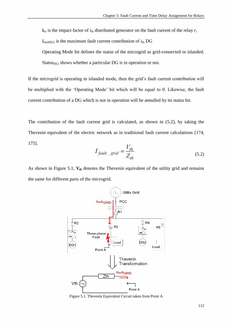
Chapter 5: Fault Current and Time Delay Assignment for Relays
112
kir is the impact factor of ith distributed generator on the fault current of the relay r,
IfaultDGi is the maximum fault current contribution of ith DG
Operating Mode bit defines the status of the microgrid as grid-connected or islanded.
StatusDGi shows whether a particular DG is in operation or not.
If the microgrid is operating in islanded mode, then the grid‟s fault current contribution will
be multiplied with the „Operating Mode‟ bit which will be equal to 0. Likewise, the fault
current contribution of a DG which is not in operation will be annulled by its status bit.
The contribution of the fault current grid is calculated, as shown in (5.2), by taking the
Thevenin equivalent of the electric network as in traditional fault current calculations [174,
175].
(5.2)
As shown in Figure 5.1, Vth denotes the Thevenin equivalent of the utility grid and remains
the same for different parts of the microgrid.
Figure 5.1. Thevenin Equivalent Circuit taken from Point A

Chapter 5: Fault Current and Time Delay Assignment for Relays
113
However, Zth which denotes the Thevenin impedance between the utility grid and point of
interest varies with respect to distance. Therefore, in the above equation, Vth is a constant
value while Zth is a function of distance, i.e. Zth (d). In this case, the fault current contribution
of the grid also becomes a function of the distance and can be defined as:
(5.3)
The signal statusDGi indicates whether that DG is in operation or not. Depending on the type
of the DG, i.e. whether it is inverter interfaced or with rotating machines, IfaultDGi is calculated
as in (5.4) and (5.5), respectively. In the literature, the fault contribution of the Inverter
Interfaced DGs is reported to range between 1.2 and 2 times their rated currents [4, 80, 155].
In order to be practical and more realistic, in this research, the coefficient of 1.5 has been
selected for use since the extreme conditions (where the fault contribution is 1.2 or 2) will not
occur as frequent as conditions which require fault contribution coefficient to be 1.5 [153,
154]. On the other hand, rotating machines have mechanical characteristics similar to large
generators and, therefore, provide larger fault current [145].
IfaultDGi = IratedDGi x 1.5 (5.4)
IfaultDGi = IratedDGi x 5 (5.5)
The impact factor, namely k, has been introduced to calculate the fault current contributions
of DGs at various points in the microgrids. It takes a value between 0 and 1 and represents
the decrease in the fault current due to the impedance of low voltage distribution lines. The
impact of the fault current contribution of a particular DG lessens as we get further away
from the source of that DG due to increasing impedance between that DG and the point of
concern. Thus, the relays closer to the DG under consideration will have higher `kir` levels
whereas those which are further downstream or upstream will have lower coefficients. In this
way, not only the effect of distribution lines can be taken into account but also a more

Chapter 5: Fault Current and Time Delay Assignment for Relays
114
flexible and versatile protection system can be designed. This is especially desirable for
growing networks with potential new deployments.
The fault currents of IIDGs do not vary with distance but with their control loops [176].
Therefore, the impact factor k does not apply to IIDGs. It has been introduced to account for
the variation of fault current contribution of rotating DGs such as diesel generators or wind
generators. In fault current calculations, the impact factors of IIDGs can be adjusted to fine
tune the fault current calculated in (5.4). This introduces extra versatility to the proposed
system, if in the future, better fault current estimation schemes are developed for different
inverters with different topologies and control schemes. However, in this study the impact
factors are taken as 1 for IIDGs and their fault contributions are worked out from (5.4). On
the other hand, the calculation of the k factor for rotating DGs is a crucial part of this
protection system and has been detailed in the following sections.
5.3. Calculation of DG impact factor – k
Figure 5.2 shows a section of a microgrid where DG1 and Relay 4 are separated by a distance
of “x”. At point A, which is the connection point of the DG1, the entire fault current
contribution (IfaultDG1) of DG1 is experienced. . At a distance of x from DG1, at point B, this
current decreases to k14 * IfaultDG1.
Figure 5.2. Fault Contribution of DG at different locations

Chapter 5: Fault Current and Time Delay Assignment for Relays
115
In order to calculate the impact coefficient, consider the symmetrical representation of this
system under fault conditions given in Figure 5.3. This representation is based on the
symmetrical components calculations [177].
Figure 5.3. Symmetrical components scheme
Since these faults are steady faults, Rf is assumed to be zero [178]. From the electrical
equation for the direct loop voltage, the following equation can be written:
(5.6)
Where Vd is the direct voltage output of DG, Ztd is the output impedance, and Vdm is the rated
output voltage of DG which is regulated by the stability and safety code of the grid. Idm is the
fault current supplied, Zd is the impedance of the transmission/distribution line per length and
x is the distance between DG and the relay under consideration.
The fault current supplied is the maximum fault current available, i.e. IfaultDG; and Vd becomes
the rated voltage of the DG. Different fault current capacities of DGs are represented by this
output impedance. Rearranging (5.6), the fault current equation can be written in terms of the
impedances and the distance as:
(5.7)
There are two unknown parameters in this equation. In order to work them out, an additional
equation is required. This is the voltage relation between Vd and Vdm, which is the voltage

Chapter 5: Fault Current and Time Delay Assignment for Relays
116
that needs to be sustained according to the stability and safety code of the grid. It can be
written as in (5.8):
(5.8)
Replacing Vd in (5.6), Idm can be expressed as:
(5.9)
In this fashion, a DG‟s fault current contribution at a distance x can be calculated. Note that
all the parameters on the right hand side of (5.9) are known before any fault occurs. This
allows the MCPU to calculate all fault contributions and assign overcurrent thresholds to the
relays for proper operation. Once the fault current contribution Idm is calculated, the impact
factor can be expressed as the ratio of Idm to IfaultDG:
(5.10)
Where i and r denote the DG and the relay under consideration. The protection system will
create a K matrix by calculating the impact factors of i-many DGs on r many relays.
(5.11)
From (5.4) and (5.5), the maximum fault currents of every DG can be calculated and the
vector IfaultDG, having dimensions [1, i] can be represented as shown in (5.12).
(5.12)

Chapter 5: Fault Current and Time Delay Assignment for Relays
117
The overcurrent thresholds of relays which represent the thresholds for relay operation can be
calculated by the cross product of matrix KT and vector IfaultDG. The result is the relay
overcurrent threshold vector of dimension [r, 1], Irelay.
(5.13)
This equation can be written in compact form as;
(5.14)
MCPU will assign each row of the vector Irelay to the related relay in the network. With the
help of communication lines, the network will be monitored and these values will be
constantly re-calculated and updated.
During the course of this work, only balanced three-phase to ground faults have been
considered. It is assumed that the microgrids are considerably smaller than the conventional
electrical networks. This means that the size of a microgrid is suitable for protection with
delayed-type instantaneous relays which implement definite-time grading technique. In the
case of a communication failure, the protection scheme can still provide reliable protection
until the communication is restored. This is because the communication infrastructure is only
critically needed for the update of protection settings. The latest fault current settings shall be
kept in the relay until the link reconnects.
Thanks to the local decision making scheme of the proposed method, the relays will be able
to operate based on these fault current settings. In this fashion, though it may not have the

Chapter 5: Fault Current and Time Delay Assignment for Relays
118
most desirable settings, the protection system will be active in case of a communication
failure and the microgrid will be protected from catastrophic conditions. The likelihood of a
communication system failure right at the point when protection setting updates would be
required is very low. It is possible to design a redundant communication network by having
multiple meshed lines connect to various switches that relays connect to. Although this will
add to the overall implementation cost, it is quite often realized in star topology
communication networks especially when high reliability is required.
In this research, only the faults occurring in the microgrid have been considered. Faults in
other feeders and/or grids are not discussed in this work. Since the microgrids under
consideration are assumed to be sufficiently small, the relays are close to the fault locations in
each branch. That is to say, the fault current magnitude does not differ significantly between
the actual location of fault and the location of the relay for which the calculations are carried
out. This protection scheme has been developed for radial electrical networks. Should an
algorithm be developed to assign proper fault current settings and adjust relay hierarchy, the
system can be extended to non-radial networks such as ring or meshed networks.
5.4. Relay Hierarchy adjustment for selectivity
Selectivity is a vital concept in protection systems. It refers to isolating the fault with the
nearest circuit breaker so that the rest of the system will not be affected in case of a fault. It
requires circuit breakers to react according to a hierarchy. The circuit breakers which are
downstream and closer to the fault point are required to operate first. However, if the fault
current is very large and the downstream circuit breaker fails to interrupt, then the upstream
circuit breaker with larger capacity should operate and isolate the fault. With the introduction
of DGs, the very traditionally accepted concepts of downstream and upstream circuit breakers
are prone to change according to the status of the microgrid. Consider the system shown in

Chapter 5: Fault Current and Time Delay Assignment for Relays
119
Figure 5.4. This network has generators connected to all branches. Through the combination
of circuit breakers, various alternative network structures can be formed.
Figure 5.4. A sample microgrid
Throughout this section, relays will be referred to being closed or open as a shortcut to
indicate the open/closed status of the Circuit Breakers (CBs) associated with each relay.
Assume that R1, R2, R3, R4, R6 and R7 are closed whereas R5 remains open. When a fault
occurs at the terminals of Load 2, then the most downstream CB will be Load 2‟s own CB
(represented by the little box) and selectivity implies that its associated relay should interrupt
the fault. If Load 2‟s circuit breaker fails to achieve that in a predetermined time (delay), then
the proper selectivity requires that R6 operates.
The proposed algorithm employed by the MCPU determines the network structure according
to the status of critical relays. The status of a critical relay changes the structure of the
network. Following this definition R1, R2, R3, R4 and R6 are all critical relays whereas Load
2‟s relay and DG1‟s relay are non-critical relays. After determining the microgrid structure,

Chapter 5: Fault Current and Time Delay Assignment for Relays
120
MCPU assigns 2-pair selectivity couples. Table I shows the 2-pair selectivity data for the left
branch of the example given above.
TABLE 5.1. 2-PAIR SELECTIVITY METHOD DATA
Relay ID Operating Current Downstream Relay ID Downstream Relay Operating Current
R2 IrelayR2 R3 IrelayR3
R3 IrelayR3 IRDG1 IrelayIRDG1
R3 IrelayR3 IRDG2 IrelayIRDG2
R3 IrelayR3 IRLoad1 IrelayIRLoad1
The method owes its name to the fact that every relay is paired up with its downstream relay.
The information provided includes; the operating current of that particular relay and the
operating current of its downstream relay. Whenever a fault occurs, the relay which is closest
to the fault operates to isolate the fault. If it proves to be unsuccessful in a predetermined time
(i.e. time delay of the upstream relay), then its upstream relay will recognize and isolate the
fault. Figure 5.5 shows the flow chart implemented by each relay for 2-pair selectivity
method.
Figure 5.5. 2-pair Selectivity Method Algorithm
Let‟s consider the case in Table 5.1 the pairs are R2-R3 and R3-I.R. Should a fault occur at
Load 1, Individual Relay (I.R.), which is the connecting relay of generators or loads, should

Chapter 5: Fault Current and Time Delay Assignment for Relays
121
isolate the fault. If unsuccessful, when the predetermined time expires (e.g. 200 msec), its
upstream relay, i.e. R3 isolates the fault. In this manner, the proposed system can be
implemented in simple and complex microgrids.
The value of the time delay (i.e. 200 msec) has been assigned by considering different
factors. It is enforced by the stability parameters that a fault shall be cleared before a
maximum time when the network becomes unstable [179]. At the same time, practical
considerations for over-current relay communication and operation imply that there is a
minimum time that these CBs can operate [180, 181]. Therefore, the time delay has been
selected to be between these minimum and maximum time values.
To further clarify the operation of the algorithm four different structures of the system shown
in Figure 5.4 are studied. These are;
1. R2, R3, R4 and R6 are closed. The middle bus is fed through R6 connection.
2. R2, R3, R4 and R5 are closed. The middle bus is fed through R5 connection.
3. R2, R3, R5 and R6 are closed. The middle bus and the right bus are fed through R5
and R6 connections, respectively.
4. R2, R4, R5 and R6 are closed. The left bus and the middle bus are fed through R5 and
R6 connections, respectively.
It is required that these cases are studied by engineers and proper hierarchy of the critical
relays should be determined and saved in the MCPU. While monitoring the network, MCPU
will also monitor the status of critical relays. In accordance with the changes in their status,
MCPU will compare the present structure with the predetermined structures saved in the
memory. After determining the present structure, MCPU will retrieve the critical relay
hierarchy pertaining to it and assign 2-pair selectivity. Alternatively, the graph theory-based
approach developed by the authors [182] and presented in Chapter 4 can be utilized to extract

Chapter 5: Fault Current and Time Delay Assignment for Relays
122
the relay hierarchy. In this fashion, the system acquires higher independence and plug-and-
play concept can be realized.
For each case given above, the proper critical relay hierarchy is given in Table 5.2. As shown,
these cases have independent branches in microgrid. That means critical relays in these
branches are elements of discrete sets and do not belong to same 2-pair distribution. For
instance, in Case 1, R3 and R4 are discrete from each other and thus they are not considered
simultaneously for 2-pair distribution. R3 is considered for 1st branch whereas R4 is
considered for 2nd
branch.
TABLE 5.2. CRITICAL RELAY HIERARCHY FOR VARIOUS CASES
Case No. 1st Branch 2
nd Branch 3
rd Branch
1. R2>R3>I.R* R2>R4>R6>I.R R2>R4>R7>I.R
2. R2>R3>I.R R2>R3>R5>I.R R2>R4>R7>I.R
3. R2>R3>I.R R2>R3>R5>I.R R2>R3>R5>R6>R7>I.R
4. R2>R4>R6>R5>I.R R2>R4>R6>I.R R2>R4>R7>I.R
*I.R. – Individual Relays of components (small boxes in figures)
TABLE 5.3. RELAY PAIRING FOR CASE 1
Relay Hierarchy 1st branch Selectivity pairs
3 R2
2 R3
1 I.R.
2nd
branch
4 R2
3 R4
2 R6
1 I.R.
Case 3 can be considered as a single branch since, due to its single line structure, 3rd
branch
covers 1st and 2
nd branches. In these cases, none of the relays are discrete and they are all

Chapter 5: Fault Current and Time Delay Assignment for Relays
123
considered in the same time for 2-pair distribution. If the network operates under Case 1 then,
1st and 2
nd branches will have the 2-pair assignments shown in Table 5.3.
As shown in Figure 5.6, when R3 opens and R4 closes the structure changes from that of
Case1 to that of Case 3. For this new microgrid structure, the relay hierarchy and 2-pair
assignments shall be updated. The place of relays in the relay hierarchy may, also, change.
R6 for instance is at 2nd level of 2nd
branch in Case 1 while it is placed at 3rd
level in Case 3.
(a)
(b)
Figure 5.6. The network structure change from Case 1 (a) to Case 3 (b)

Chapter 5: Fault Current and Time Delay Assignment for Relays
124
As shown in Table 5.2, for Case 3, there is only one branch with 5 hierarchy levels.
Therefore, 2-pair assignment for this case is as shown in Table 5.4. When Table 5.3 and
Table 5.4 are compared, it becomes evident that the pairing of the relays change and they
need to be updated. A reliable communication is vital for this purpose. In similar fashion, the
protection system will recognize any new structure and repeat pairing process according to
Table 5.2.
TABLE 5.4. RELAY PAIRING FOR CASE 3
Relay Hierarchy 1st branch Selectivity pairs
5 R2
4 R3
3 R5
2 R7
1 I.R.
If an automatic relay hierarchy detection algorithm such as in [182] is not utilized, then it has
utmost importance that the network operators have their power engineers study possible
network structures of the microgrid, list the proper hierarchy of the relays and prepare Table
5.2. MCPU will automatically operate according to these data.
5.5. Faults outside the microgrid
One exceptional case arises when a fault occurs outside the microgrid, i.e. in the utility grid.
Since the fault is in the utility grid, the microgrid should be isolated from the system by
opening R1. In this case, the interfacing relay R1, which is at the top of the relay hierarchy, is
required to operate first. Figure 5.7 shows the fault currents and the inversed selectivity
hierarchy under these circumstances.

Chapter 5: Fault Current and Time Delay Assignment for Relays
125
Figure 5.7. Faults in the Utility Grid
In order to address this issue, it is requires that relays must have directional overcurrent and
directional power capabilities. As proposed earlier, these capabilities are necessary for
bidirectional operation [73, 162]. The proposed system, which is a combination of fault
current and relay hierarchy assignment, is implemented bidirectionally. DGs‟ fault
contribution will be calculated for the critical relays through which they are connected to the
utility grid.
Referring to the system in Figure 5.7, for instance, reverse overcurrent threshold of R2 will
include the contributions of DG1 and DG2. Once the reverse overcurrent thresholds are
calculated, the relay hierarchy order will be exactly the opposite of order given in Table 5.2.
This means when a fault outside the microgrid occurs and the fault current flows in reverse
direction (i.e. upstream), R1 will act first and isolate the microgrid from the fault. If, for any

Chapter 5: Fault Current and Time Delay Assignment for Relays
126
reason, it fails to interrupt the current, reverse selective hierarchy imposes that R2 must
interrupt the reverse fault current.
TABLE 5.5. BIDIRECTIONAL PARAMETERS FOR CASE 1
1st branch R2 R3 I.R.
Forward Pair R3 I.R. N/A
Reverse Pair R1 R2 R3
Forward Current IrelayFR2 IrelayFR3 IrelayFI.R.
Reverse Current IrelayRR2 IrelayRR3 IrelayRI.R.
2nd branch R2 R4 R6 I.R.
Forward Pair R4 R6 I.R. N/A
Reverse Pair R1 R2 R4 R6
Forward Current IrelayFR2 IrelayFR4 IrelayFR6 IrelayFI.R.
Reverse Current IrelayRR2 IrelayRR4 IrelayRR6 IrelayRI.R.
3rd branch R2 R4 R7 I.R.
Forward Pair R4 R7 I.R. N/A
Reverse Pair R1 R2 R4 R7
Forward Current IrelayFR2 IrelayFR4 IrelayFR7 IrelayFI.R.
Reverse Current IrelayRR2 IrelayRR4 IrelayRR7 IrelayRI.R.
In order to realize this in a systematic way, relays should have four different parameters, as
shown in Table 5.5. In this table, each relay has two relay-pairing (forward & reverse) and
fault current parameters, one for forward (downstream) and one for reverse (upstream) fault
current flows. Two relay currents shall be calculated individually by considering fault current
contributions of various DGs. Pairing of the relays for 2-pair selectivity, on the other hand,
can be calculated at once. The reverse relay hierarchy is extracted by inverting the forward
hierarchy and the assignment is trivial.
This additional feature can easily be implemented in the MCPU if the relays have the
capability to operate in both directions. Such relays are called directional overcurrent relays
and an example can be found in [183]. MCPU will calculate two different overcurrent
Chapter 5: Fault Current and Time Delay Assignment for Relays
127
thresholds, namely forward and reverse fault currents, and should the fault current flow in
reverse direction, the Critical Relay Hierarchy will be reversed.
5.6. Reliability considerations
The protection systems in electrical networks play a vital role in sustaining stability and
ensuring safe operation. With the development of new technologies, protection systems
became more complex. Significant progress has been recorded in power system reliability
modeling and computation by applying quantitative analysis based on probability theory
[184]. In recent years, different reliability assessment methods have been proposed such as
Reliability Block Diagram (RBD) [185], 3RF Technique [186], and Software Reliability
Allocation [187]. The failures are classified and new parameters are introduced to design a
more comprehensive reliability assessment scheme [184, 188].
These systems consider issues related to relay hardware, relay software, ancillary equipment,
communication units and human errors. [186, 188]. All of them consider the probability of a
failure occurrence and its impact on system dependability and security as defined by IEEE
standard C37.100-1992 [189]. The probability of a failure is defined by [187, 190]:
(5.15)
where all the individual probability components are added to find the overall value. If there is
more than one event that is required for a failure to occur then the combined probability can
be expressed as in (5.16).
(5.16)
where n is the total number of independent events.

Chapter 5: Fault Current and Time Delay Assignment for Relays
128
As mentioned in earlier sections, in case of a communication failure, the developed
protection system implements a “last-setting-valid” approach. Figure 5.8 shows the local
decision making mechanism employed to activate the circuit breakers. As shown, the
operation is independent of the communication link and this ensures that relays are always set
to operate, though it may not be the most desirable operation point.
Figure 5.8. Local Decision Making scheme in Relays
However, this requires two events: 1) a failure in the communication line, 2) an electrical
fault in the network before the communication line is restored. Therefore the probability of a
relay operating following “last-setting-valid” method is the multiplication of the probabilities
of communication link failure and electrical fault:
P[commfault]=P[comm] x P[fault] (5.17)
where P[comm] is the probability of a communication failure occurring in the microgrid
while P[fault] is the probability of an electrical fault occurring in the same microgrid.
Equations 15 and 16 hold for all conditions except for extreme climate conditions where
power system fault follows power law distribution instead of exponential distribution [191].
Extreme weather conditions are not considered in this study.
It is clearly mentioned in the literature that with the improving technology the hardware
failures are less frequent [187]. Consequently, the value of probability of communication

Chapter 5: Fault Current and Time Delay Assignment for Relays
129
failure is very small. The values assumed for these probability values are on the order of 10-2
or 10-3
[188, 190]. For short term analysis these values may drop as low as 10-5
[192].
Accordingly, replacing these characteristic values in (5.17) yields:
P[commfault]=0.01 x 0.001 = 10-5
(5.18)
As a result, the developed protection system proves to be reliable in accordance with the
requirements of the standards [189]. Considering the value of P[commfault], it is concluded
that the possibility of relays operating when there is a communication failure is very small.
Even if they are forced to operate before the communication is restored, the implementation
of “last-setting-valid” method ensures that no catastrophic condition occurs.
As long as the communication speed is at permissible levels, the communication speed is not
vital. Communication is only required for updating relay settings and this occurs when a DG
connects to or disconnects from the grid. In case of a fault, no communication is required as
relays operate based on Local Decision Making. If, as an exceptional case, a fault occurs just
after a Relay Setting Update process has started, then the regular communication speed is
around 80 ms [193] and this ensures that relay settings will be updated and the fault will be
cleared before maximum allowed time expires.
5.7. Conclusion
This chapter has presented two procedures to assign two key parameters in a microgrid
protection system with a real time protection controller such as an MCPU. The first of these
parameters is the DG impact factor „k‟ which is important in accurately anticipating the fault
current contributions of DGs‟ over a relay. The calculation of the impact factor involves
parameters which are known beforehand. Hence, „k‟ can be calculated before the fault
actually occurs. Secondly, an algorithm to adjust the hierarchy of relays for proper selective

Chapter 5: Fault Current and Time Delay Assignment for Relays
130
operation in microgrids has been presented. The concepts of critical relay and 2-pair
selectivity have been introduced. The procedure is automated as much as possible by
decreasing human input to minimum. The developed system can work autonomously when
the possible network structures and corresponding relay hierarchies are supplied in a table.
Alternatively, automatic relay hierarchy extraction algorithms, such as the one discussed in
Chapter 4, can be utilized and this makes the protection system more robust and independent.
The faults occurring outside the microgrid have also been considered. It is explained how this
situation necessitates the protection system to be able to detect and act on directional over-
currents. The proposed protection system has been adapted as it is but the calculation and
assignment of the k factor and relay selectivity has been modified to suit all cases including
the possibility of faults outside the microgrid. As a result, a complex centralized microgrid
protection system has been developed and its operation principles and calculation/assignment
procedures have been presented in detail.
Finally, the reliability considerations performed in accordance with the reliability assessment
methods presented in the literature, has shown that the developed protection system is very
reliable in the case of a fault. The selectivity pairs ensure that even if a malfunction occurs in
one of the protective devices, total collapse of protection system will be avoided.
In summary, the main intellectual contribution of the work presented in this Chapter has been
the development of an adaptive algorithm, which calculates and assigns protection settings on
the go. The developed adaptive scheme is able to follow the dynamic changes occurring in
the microgrid, easily accommodate new deployments and adjust the necessary settings.

Chapter 6: IEC 61850-Based Modeling of the Microgrid Protection System
131
Chapter 6
IEC 61850-Based Modeling of the Microgrid Protection System
Publications pertaining to this chapter:
1) Taha Selim Ustun, Cagil Ozansoy, Aladin Zayegh, "Modeling of a Centralized Microgrid Protection
System and Distributed Energy Resources According to IEC 61850-7-420," IEEE Transactions on
Power Systems, , vol. PP, pp. 1-8, 2012.
2) Taha Selim Ustun, Cagil Ozansoy, Aladin Zayegh, "Distributed Energy Resources (DER) Object
Modeling with IEC 61850-7-420," In the Proceedings of the Australasian Universities Power
Engineering Conference, AUPEC '11, Brisbane, Australia, 2011.
3) Taha Selim Ustun, Cagil Ozansoy, and Aladin Zayegh; “Extending IEC 61850-7-420 for Distributed
Generators with Fault Current Limiters”; In the Proceedings of IEEE PES International Conference on
Innovative Smart Grid Technologies ASIA (ISGT Asia),, Perth, Australia, 13-17 Nov., 2011.
4) Taha Selim Ustun, Cagil Ozansoy, Aladin Zayegh,, "Implementing Vehicle-to-Grid (V2G) Technology
with IEC 61850-7-420," , IEEE Transactions on Smartgrids, vol.PP, (accepted).
6.1. Introduction
The preceding chapters explain the modular approach assumed in this research, for the design
of the protection system. Firstly, a conceptual design has been developed with contemporary
protection challenges in mind. It has been shown that the design is flexible and can be
adapted for different grid components such as FCLs. Secondly, the automated microgrid
structure detection which is a key part of this research has been explained. This feature

Chapter 6: IEC 61850-Based Modeling of the Microgrid Protection System
132
enables the developed microgrid protection system to be versatile so that it can be applied on
microgrids with changing structures. It also facilitates new deployments. Thirdly, it has been
shown how the necessary protection parameters are calculated in this system. It has been
elaborated upon how the first two research steps are utilized in the parameter calculation
process and thus, a complementary system is achieved.
Similar to previous chapter, this chapter builds upon the previous achievements of this
research. It shows how the developed conceptual design with automated approach and
parameter assignment features can be implemented with an international communication
standard, i.e. IEC 61850 and its recent extension for DER based systems IEC 61850-7-420.
This is an important aspect of the developed microgrid protection system, especially from
universality, versatility and flexibility perspectives. The work presented in this chapter shows
that the developed multi-dimensional protection system can be implemented with
international and universal communication standards. Hence, it is suitable for various
implementations in different microgrid topologies. It fills a major gap that is related to the
need of a standard communication infrastructure which does not depend on the microgrid
structure, its components or the manufacturers thereof.
6.2. IEC 61850 International Standard
It has been expressed earlier that in order to sustain a safe operation in dynamic microgrid
structures, which have numerous parameters and variables (data) to be monitored,
communicated and controlled, a new management strategy with extensive communication
capability is required. The need for extensive communication between the microgrid
components is widely accepted in the Power Engineering field. In an effort to standardize the
communication methods and the data to be communicated, the IEC 61850 standard is issued

Chapter 6: IEC 61850-Based Modeling of the Microgrid Protection System
133
by International Electrotechnical Commission (IEC). Furthermore, this standard has been
extended with IEC 61850-7-420 for the modeling of DER based generators.
In this chapter, the developed protection system has been modeled with logical nodes and
data sets provided by IEC 61850-7-4 [194] and IEC 61850-7-420 [132]. Using a standardized
method to model these systems and their components is crucial for wide-spread acceptance of
microgrids [195]. Having universal data and information exchange models for microgrid
protection systems will ease the modeling and the system will be open to new deployments or
alterations [196]. Since the models do not depend on the manufacturer or the ratings of the
components, this is a major step toward realization of plug-and-play concept [133, 167].
IEC 61850 is an international communication standard aimed at reaching a universal
communication infrastructure in electrical systems. It uses Object Oriented (OO) modeling
for the equipment and their functionalities. IEC 61850 effectively reduces the burden of
communication infrastructure modeling by virtual modeling of physical devices in a standard
manner. Furthermore, it also defines necessary procedures for data transfer and client/server
interactions between the equipment in an electrical network.
The Generic Object Oriented Substation Event (GOOSE) is widely accepted as the most
important one of the data transmission services defined in IEC 61850. GOOSE is a fast
connection-less communication service used for the transfer of time critical data where high
speed and security are achieved by the repetition of messages a number of times. One of the
most significant architectural constructs of the IEC 61850 is the adoption of an “abstracting”
technique, which involves the creation of objects that are independent of any underlying
protocol. The isolation of the information models and information exchange services from the

Chapter 6: IEC 61850-Based Modeling of the Microgrid Protection System
134
underlying on-the-wire protocols is usually seen as one of the most powerful capabilities of
the IEC 61850 standard. Abstract means that the standard focuses on describing what the
services are indented to provide rather than how they are build.
The abstract nature of the definitions permits the mappings of the data objects and services to
any other protocol, which provides adequate communication procedures meeting the data and
service requirements of the IEC 61850 standard. Currently, IEC 61850 only specifies
mappings on a communication stack that includes the Manufacturing Message Specification
(MMS) over the Transmission Control Protocol/Internet Protocol (TCP/IP) and Ethernet.
However, the potential need to support mappings to different communication models has
clearly been recognized in the industry and examples do exist in the literature detailing such
mappings. Although not addressed in IEC 61850, it is possible to implement the standard‟s
object models and services by mapping to other different communication stacks such as the
Distributed Component Object Model (DCOM) or Common Object Request Broker
Architecture (CORBA).
Substation Automation Systems (SASs), used for controlling substations, are usually
composed of a number of Intelligent Electronic Devices (IEDs) interconnected through a
network of high-speed communications with widespread routers and switches [9]. IEC 61850
has the objective of enabling interoperability between IEDs within a substation by defining
standard object (information) models for IEDs and functions within a SAS [10]. As a result, it
standardizes the language of communication between the SAS devices allowing for the free
exchange of information. Although the IEC 61850 set of documents is comprised of 10 parts,
the most important contents are found in Parts 7-x:

Chapter 6: IEC 61850-Based Modeling of the Microgrid Protection System
135
IEC 61850-7-1: Principles and models.
IEC 61850-7-2: Abstract Communication Service Interface (ACSI).
IEC 61850-7-3: Common Data Classes (CDCs)
IEC 61850-7-4: Compatible logical node classes and data classes.
Functions in a SAS are defined by modeling the syntax and semantics of the exchangeable
application-level data in devices as well as the communication services required to access this
data. An important point to clarify is that the IEC 61850 standard only attempts at
standardizing the communication visible behaviors of functions rather than their actual
internal operations.
Parts 7-2, 7-3, and 7-4 form the three levels of this process. Part 7-2 specifies the basic layout
for the definition of the substation-specific information models and information exchange
service models. Part 7-3 specifies CDCs and common data attribute types, which are the main
building blocks of the LN and Data classes described in Part 7-4. The Logical Node (LN) and
Data classes form the elements that allow the creation of the information model of a real
substation device. They are the most vital concepts used in the standard to describe real-time
substation systems. Further information on IEC 61850 and its application can be found in
these references [11] [12].
The model-driven approach of the IEC 61850 standard describes the communication between
devices in a substation and the related system requirements. Throughout the preparation of
IEC 61850 standard International Electro-technical Commission identified the several aspects
of devices which are crucial for proper operation. [197]

Chapter 6: IEC 61850-Based Modeling of the Microgrid Protection System
136
6.3. Modeling DER Systems with IEC 61850-7-420 Extension
Soon after its publication IEC 61850 received much attention in power engineering circles as
it addressed a vital aspect of communication lines in power systems. In an effort to encourage
its utilization in microgrids which have more DG deployments, IEC formed the Workgroup
(WG17) to publish an extension of IEC 61850-7-4 Compatible logical node classes and data
classes. This extension aimed at having logical nodes and data classes that will help in
modeling DER systems effectively. In addition, IEC 61850-7-420 can be further extended for
components which are not readily available in this standard. An example of this can be seen
under Section (6.4) “Extending IEC 61850-7-420 for New Grid Components” where the said
standard has been extended with information and data exchange models for fault current
limiters [149] and EVs [147].
Figure 6.1. Generic DER system in IEC 61850-7-420 [197]
The overall system given in Figure 6.1 is used a template for modeling the DER systems
given below; (See Appendix – D for examples of DER modeling with IEC 61850-7-420)

Chapter 6: IEC 61850-Based Modeling of the Microgrid Protection System
137
Diesel Generators
Solar panels (PV)
Fuel Cells
Combined Heat and Power
In addition to switching DERs on and off, DER systems involve:
Management of the interconnection between the DER units and the power systems
they connect to, including local power systems, switches and circuit breakers, and
protection.
Monitoring and controlling the DER units as producers of electrical energy
Monitoring and controlling the individual generators, excitation systems, and
inverters/converters
Monitoring and controlling the energy conversion systems, such as reciprocating
engines (e.g. diesel engines), fuel cells, photovoltaic systems, and combined heat and
power systems
Monitoring and controlling the auxiliary systems, such as interval meters, fuel
systems, and batteries
Monitoring the physical characteristics of equipment, such as temperature, pressure,
heat, vibration, flow, emissions, and meteorological information
It has been observed that two distinct colors have been used to denote LNs. The blue color
indicates that this particular LN has been included in IEC 61850-7-4 Logical Node Classes
list whereas red color indicates that this LN has been introduced with the recent extension
IEC 61850-7-420 Logical Node Classes.
The system assumes a holistic sense in which the DER systems are modeled considering their
internal parameters, their grid connection types and parameters, and microgrid operator

Chapter 6: IEC 61850-Based Modeling of the Microgrid Protection System
138
command and control units. This may include fuel type for diesel generators, battery test
results for solar panels or hydrogen level for fuel cells. Having detailed characteristics
variables and measurement values entrenched inside, this modeling system serves for a
rigorous communication system. In order to give a better insight about modeling DER
systems according to the mentioned publication, the new LN classes and data classes shall be
explained in four groups which are; DER unit controller, internal parameters, grid connection
and network operator units.
6.3.1. DER Unit Controller
The four LNs given at the top of Figure 6.1, under this heading DRCT, DRCS, DRCC and
FSEQ comprises the DER unit controller Logical Device (LD). These LNs are aimed at
providing extensive information on the DER controller characteristics, its status and the
supervisory control actions that can be undertaken.
DRCT represents a controller which controls a single DER or a group of DERs connected to a
single controller. Among other parameters it is required to input the number of DERs
connected to it, types of these DERs and maximum output power values.
DRCS provides information on the status of the controller such as its electrical connection,
operation mode: automatic or manual, control mode: local or remote etc. By changing these
parameters, it is possible to control a DER‟s electrical connection to the grid from a remote
controller or, if it is required, only local and manual control might be enabled. In either case
full representation of these data will be present in this logical node.
DRCC represent the supervisory control on DER and it has a full list of actions that can be
executed for desired control. Setting different operating points, changing time delays,
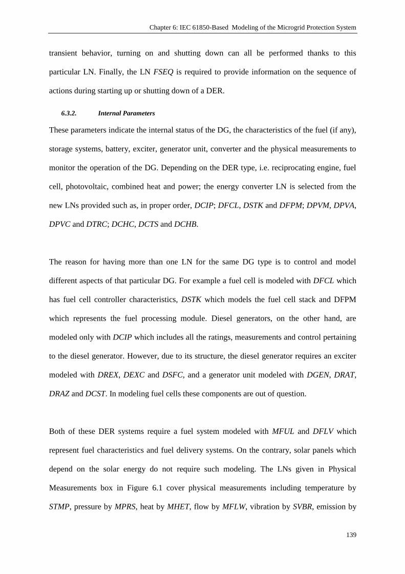
Chapter 6: IEC 61850-Based Modeling of the Microgrid Protection System
139
transient behavior, turning on and shutting down can all be performed thanks to this
particular LN. Finally, the LN FSEQ is required to provide information on the sequence of
actions during starting up or shutting down of a DER.
6.3.2. Internal Parameters
These parameters indicate the internal status of the DG, the characteristics of the fuel (if any),
storage systems, battery, exciter, generator unit, converter and the physical measurements to
monitor the operation of the DG. Depending on the DER type, i.e. reciprocating engine, fuel
cell, photovoltaic, combined heat and power; the energy converter LN is selected from the
new LNs provided such as, in proper order, DCIP; DFCL, DSTK and DFPM; DPVM, DPVA,
DPVC and DTRC; DCHC, DCTS and DCHB.
The reason for having more than one LN for the same DG type is to control and model
different aspects of that particular DG. For example a fuel cell is modeled with DFCL which
has fuel cell controller characteristics, DSTK which models the fuel cell stack and DFPM
which represents the fuel processing module. Diesel generators, on the other hand, are
modeled only with DCIP which includes all the ratings, measurements and control pertaining
to the diesel generator. However, due to its structure, the diesel generator requires an exciter
modeled with DREX, DEXC and DSFC, and a generator unit modeled with DGEN, DRAT,
DRAZ and DCST. In modeling fuel cells these components are out of question.
Both of these DER systems require a fuel system modeled with MFUL and DFLV which
represent fuel characteristics and fuel delivery systems. On the contrary, solar panels which
depend on the solar energy do not require such modeling. The LNs given in Physical
Measurements box in Figure 6.1 cover physical measurements including temperature by
STMP, pressure by MPRS, heat by MHET, flow by MFLW, vibration by SVBR, emission by

Chapter 6: IEC 61850-Based Modeling of the Microgrid Protection System
140
MENV, meteorological conditions by MMET. These measurements may belong to the fuel,
generator, and auxiliary systems for heating, cooling, lubrication; and environmental
conditions that are crucial in ensuring safe and efficient operation.
6.3.3. Grid Connection Units
These LNs comprise the components which are required, or might be required depending on
the DER type, for proper gird connection. DER circuit breakers and Utility Circuit breakers
which are modeled with CSWI and XCBR are required for every DG connection. In a unique
fashion, IEC 61850-7-420 proposed a LN named XFUS, which is used to model a fuse and it
can be compared to a circuit breaker for one-time use.
The diesel generator requires the synchronizer RSYN so that its output is synchronized with
the grid. As known, fuel cells and solar panels yield DC output. A DC switch modeled with
XSWI or CSWI is required to feed the output to the converter. The converter converts the DC
output to AC voltage and synchronizes the output in this process. Depending on the situation,
converters are modeled with ZRCT and ZINV.
ZRCT is used in modeling rectifiers which converts generator output AC to intermediate DC.
Properties can be set in detail such as types of commutation, isolation, voltage regulation,
conversion (AC-DC, AC-AC-DC, AC-DC-DC), cooling method, AC system and filter types.
Furthermore, current and voltage limits can also be set. ZINV is used in modeling inverters
which converts DC input (either directly from a generator or intermediate DC fed by ZRCT)
to AC. Properties can be set in detail such as switch type, cooling method, type of
commutation, isolation, switching frequency and current connect mode. Furthermore, current
and voltage limits can also be set.

Chapter 6: IEC 61850-Based Modeling of the Microgrid Protection System
141
6.3.4. Network Operator Units
These LNs are required to model Electrical Connection Point (ECP) LDs and aimed at sorting
out the issues related to Network operation such as legal information (ownership, authority,
obligations and permissions), technical characteristics (types of DER devices, connection
types, operation modes, ratings), control authority permissions and other management
information.
In brief at each ECP, DCRP includes DER plant corporate characteristics (such as ownership,
contractual obligations and permission), DOPR has DER plant operational characteristics
(such as DER device types, ratings, connection types, operation modes), DOPA has
information on DER operational control authorities (who has the authority to switch on/off
DGs or switches), DOPM is used to either get information about or set the operating mode of
DGs, DPST represents the actual status at ECP including alarms and connection status,
DCCT has the economic dispatch parameters, DSCC is used to control energy and ancillary
services schedules and DSCH is the schedule for DER plant to provide energy and/or
ancillary services.
6.4. Extending IEC 61850-7-420 for New Grid Components
Due to the amount of attention IEC 61850 received worldwide, the IEC formed Work Group
17 (WG17) to develop and publish an extension to the IEC 61850-7-4: Compatible logical
node classes and data classes, i.e. IEC 618520-7-420 [12] aimed at developing and publishing
LNs and data classes so that one common standard could be established for all DER devices.
Although this extension gives a comprehensive list of models and parameters to represent
various types of DERs, the standard is far from complete and still information models for
some devices are not included such as models for FCLs or EVs.

Chapter 6: IEC 61850-Based Modeling of the Microgrid Protection System
142
The ever-evolving of microgrid technologies require that the communication standard
intertwined with these technologies shall also evolve constantly and keep up with the latest
developments. During the course of this research, two important extensions have been made
to the IEC 61850 standard to include models for FCLs and EVs. The motivation behind
choosing these devices is their potential in microgrids and expected wide-spread us thereof.
Following two sub-sections reveal the details of the LNs, which have been developed for
FCLs and EVs and are being proposed in this thesis as a contribution to knowledge. The
contributions made have been discussed around the parameters chosen for command and
control, the overall modeling with LNs from IEC 61850 and from IEC 61850-7-420, the point
of connection in the grid and virtualization of the devices.
6.4.1. Fault Current Limiter Extension for IEC 61850-7-420
Regardless of the structure of the microgrid management system utilized, the development of
a comprehensible model for DGs with FCL is inevitable. The operation principle of different
FCLs outlined in the previous chapters is almost identical. Regardless of its type, an FCL
follows the fault current limitation characteristics given in Figure 6.2. Below the threshold
value, there is no control on output current and it is free-flowing. Once the threshold is
passed, a predetermined ifault is observed at the output after the reaction time (td – tƒ).
Therefore, the control parameters that are required in the communication system are the
same. These are; the threshold current (ith), the limited fault current (if), the time required for
the FCL to react (td – tƒ). These parameters are required to anticipate the behavior of the FCL
and, hence, estimate and control the transients in a network.

Chapter 6: IEC 61850-Based Modeling of the Microgrid Protection System
143
Figure 6.2. Fault current limitation for inverter topology [160].
The extension of IEC 61820-7-420 to accommodate FCL can be achieved in three different
ways:
1. Updating DRAT (direct-coupled DGs) ZINV (inverter interfaced DGs) with FCL
control parameters
2. Updating DRCT (both for direct-coupled and inverter interfaced DGs) with FCL
control parameters
3. Proposing a new block, FACL, for FCLs at DG output (placed before DER Circuit
Breaker in Figure 6.1)
The first method requires repetition of the same adjustment for each DG type while the
second method already encompasses both types of the DGs through updating DRCT block.
Since DRCT is a universal block for all types of DGs, updating its structure shall be
sufficient. Therefore, following sub-sections focus only on the latter two methods above.
6.4.1.1. Updating the DER controller LN (DRCT)
Table 6.1 shows the updated version of DRCT class which includes the data given in IEC
61850-7-420 [197] as well as the appended FCL parameters. Following the definition of IEC
61850 - Part 7.3 [198], Common Data Classes, the two current values `ThrshldCrnt` and
`FCLCrnt` are defined as Analogue Setting (ASG) class while `FCLDelay` is defined as
Integer Status Setting (ING). These parameters are indicated to be Optional „O‟ since DRCT
is a universal class for all DG controllers including DGs without a fault current limiter.

Chapter 6: IEC 61850-Based Modeling of the Microgrid Protection System
144
TABLE 6.1. UPDATED DRCT CLASS
DRCT class
Data Name CDC Explanation T M/O/C
LNName Shall be inherited from logical-node class (see IEC 61850-7-2)
Data
System logical node data
LN shall inherit all mandatory data from common logical node class M
Data from LLN0 may optionally be used O
Settings
DERNum ING Number of DER units connected to controller M
DERtyp ING
Type of DER unit:
Value Explanation
0 Not applicable / Unknown
1 Virtual or mixed DER
2 Reciprocating engine
3 Fuel cell
4 Photovoltaic system
5 Combined heat and power
99 Other
M
MaxWLim ASG Nominal max output power
MaxVarLim ASG Nominal max output reactive power M
StrDlTms ING Nominal time delay before starting or restarting M
StopDlTms ING Nominal time delay before stopping M
LodRampRte ING Nominal ramp load or unload rate, power versus time M
ThrshldCrnt ASG Threshold current for the Fault Detection O
FCLCrnt ASG The Fault Current of FCL O
FCLDelay ING Time required for the fault detection O
If a FCL is implemented in DG, these data can be updated and the microgrid management
and/or protection system can retrieve the related current and timing values through
communication system. Transient behavior estimation or fault condition planning of the
microgrid, or the DG in particular, can be done accordingly.
6.4.1.2. Information Modeling for the FCL Logical Device
The IEC 61850 standard identifies all known functions in a system and splits them into sub-
functions or so called Logical Nodes (LNs). In other words, a LN is a sub-function located in

Chapter 6: IEC 61850-Based Modeling of the Microgrid Protection System
145
a physical node, which exchanges data with other separate logical entities. LNs are virtual
representations of real devices [161]. Conforming with the same approach, a new LN, FACL,
which will be used in the representing FCLs in the virtual data communications world, has
been designed. Figure 6.3 depicts the association between FCL devices in the real world and
the LNs used in their virtualization. In this figure, FCL LD has a single LN, FACL, which
includes the necessary control and communication parameters.
Figure 6.3. Virtualization of Fault Current Limiters with proposed LNs
Table 6.2 shows the new model designed for the modeling of FCLs in an independent
manner. In addition to the parameters added in sub-section A, (`ThrshldCrnt`, `FCLCrnt`, and
`FCLDelay`) the proposed class FACL, includes several other entries on ratings which are
proposed in parallel with the existing FCL devices and datasheets [199]. There are four rating
entries which are all defined as ASG class. Of these, `VRtg` holds the rated voltage, `IRtg`
holds the rated current, PfVRtg holds the rated power-frequency withstand voltage and
`LiRtg` holds rated lightning impulse withstand voltage values. Since they are not vital to the
operation of FCL these rating entries are defined as optional (O) parameters.

Chapter 6: IEC 61850-Based Modeling of the Microgrid Protection System
146
TABLE 6.2. FACL CLASS
FACL class
Data Name CDC Explanation T M/O/C
LNName Shall be inherited from logical-node class (see IEC 61850-7-2)
Data
System logical node data
LN shall inherit all mandatory data from common logical node
class
M
Data from LLN0 may optionally be used O
Settings
ThrshldCrnt ASG Threshold current for the Fault Detection M
FCLCrnt ASG The Fault Current Value of FCL M
FCLDelay ING Time required for the fault detection M
VRtg ASG Rated Voltage O
Irtg ASG Rated Current O
PfVRtg ASG Rated power-frequency withstand voltage O
LiRtg ASG Rated lightning impulse withstand voltage O
Status Information
FaultCount INS Count of Fault Occurrences M
FCLStatus SPS True: Fault Current Limitation is ON
False: Fault Current Limitation is OFF M
FaultDetect SPS True: Fault is Detected
False: No Fault is Detected M
FCLOpticSignal SPS True: Fault Current Limitation Indicator is ON
False: Fault Current Limitation Indicator is OFF
O
FCLAudibleSignal SPS True: Fault Current Limitation Audible Signal is ON
False: Fault Current Limitation Audible Signal is OFF
O
Controls
FCLControl DPC Switch on/off, Fault current limitation, On=True, Off=False M
Measured Values
OutACV MV FCL voltage in AC volts O
OutACA MV FCL current in AC amps O
Furthermore, FACL class provides more information on the status of the FCL. `FaultCount`,
for example, holds the count of the fault occurrences for protection system planning.
`FCLStatus` belongs to Single Point Status (SPS) data class and indicates whether FCL is
switched on or off. This operation is performed with `FCLControl` variable which belongs to
Controllable Double Point (DPC) class. `FaultDetect` indicates whether the existing current
value is higher than ` ThrshldCrnt` and a fault is detected. `FCLOpticSignal` and
`FCLAudibleSignal` are optional (O) entries which indicate whether these signals are
activated.

Chapter 6: IEC 61850-Based Modeling of the Microgrid Protection System
147
Two different entries are proposed as measurement parameters. OutACV holds FCL voltage
in AC volts while OutACA holds FCL current in AC amps. Both of these parameters are
defined as Measured Value (MV) class. Not every FCL topology requires or has a
measurement device equipped on them. Therefore these measurements are defined as
optional (O). The connection of the proposed block, FACL, will be as shown in Figure 6.4.
Figure 6.4. FACL Class in Generic DER system (IEC 61850-7-420)
6.4.2. Electric Vehicle (EV) Extension
Climate change concerns and carbon emission reduction schemes make the use of EVs more
popular. The availability of the technology and the promising acceptance of Hybrid Electric
Vehicle Cars (HEVs) encourage car manufacturing companies to take solid steps towards the
EV market. Accordingly, in recent years the awareness of people about EVs increased
significantly. In addition to the well-known advantages such as zero direct emissions, less oil-
dependency, cheaper fuel, more silent operation through smart grids, EVs also offer a unique
benefit called Vehicle to Grid (V2G) technology. Through the V2G, EVs can support better
operation of smart grids in terms of reliability and storage. The statistics indicate that the
growing population demands more cars and acceptance of EVs could have benefits in
different fields such as environment, finance and energy.

Chapter 6: IEC 61850-Based Modeling of the Microgrid Protection System
148
Different car manufacturing companies have already manufactured Plug-in Hybrid Electric
Vehicles (PHEVs), EVs and Hybrid EVs (HEVs) [200-203]. The variety of EV technology
makes it possible to meet demands under different circumstances. HEVs and PHEVs can be
used for increasing the fuel efficiency and gradual introduction of EVs until the necessary
infrastructure is prepared. All the technology required for EV is readily available and the
research work focuses on improving the performance or efficiency [134].
When coupled with the smart grid technology, an EV can act as a load as well as a distributed
storage device. Being connected to the grid when not in use, battery of the EV can supply
power at peak load times and thus increase the reliability of the grid. This technology is called
the V2G technology [139]. Considering the total number of vehicles in a locality, distributed
storage capacity provided by V2G can have very large impact on the economical operation of
smart grids.
Therefore, it is a well-acknowledged fact that EVs will become an indispensable part of our
daily lives [204] as well as the electrical network [205] in near future. Being a technology
which became popular recently, EV has not been included in international communication
standards prepared for electrical networks. This section extends IEC 61850-7-420 with EV
models and, thus, fills an important knowledge gap in the literature.
6.4.2.1. Current Status of EV Technologies
There are various EV technologies available in the market. Some of the manufacturers use
HEVs to increase the efficiency of the car while others take another step towards all-electric
mode with PHEVs. Some other manufacturers, such as Tesla Motors, dedicate their efforts on
pure EVs which do not even have a tail pipe [200]. HEVs are classified as series, parallel and
series parallel [206]. Figure 6.5 shows the typical diagram of a series hybrid power train. Fed

Chapter 6: IEC 61850-Based Modeling of the Microgrid Protection System
149
by fuel tank, the internal combustion engine (ICS) charges the batteries through the
generator. The traction is provided to the wheels through battery-propulsion motor couple. In
a series power train, the ICS engine is mechanically decoupled from the wheels. This gives
the freedom to relocate ICS engine as desired. Despite expensive manufacturing costs, series
power trains are easy to design, control and implement[206]. They are also popular for larger
vehicles [134].
Figure 6.5. A HEV with a series hybrid power train
Figure 6.6 shows the topology of a parallel hybrid power train where both ICS engine and the
electric motor are mechanically coupled to the wheels. The electric motor helps increase the
efficiency of ICS engine and decrease its carbon emissions. One drawback of parallel power
trains is the inability to operate in all-electric mode at high speeds [134].
Figure 6.6. A HEV with a parallel hybrid power train

Chapter 6: IEC 61850-Based Modeling of the Microgrid Protection System
150
Figure 6.7 shows a PHEV with series-parallel hybrid power train. It possesses the advantages
of both the series and parallel hybrid trains. Since it has more components, an additional
generator compared with parallel power train and an additional mechanical link compared
with series power train. Hence, it is more expensive. Thanks to advancements in control and
manufacturing technologies, these costs are reduced and series-parallel power trains are
adopted more frequently [206]. Figure 6.7 also depicts the fundamental difference between
HEVs and PHEVs. The battery system in PHEVs has an external connection and can be
recharged independently from the operation of the ICS engine.
Figure 6.7. A PHEV with a series-parallel hybrid power train
The motivation behind hybridization is to increase the overall efficiency of the engines and
decrease emissions per unit distance. The benefits of hybridization can be summarized as
follows [134]:
Higher efficiency is obtained since electric propulsion machines are more efficient
and faster than other systems
The flexibility provided by the electric propulsion systems makes it possible to
operate heat engine at higher-efficiency region
Regenerative braking can be utilized to charge the batteries during braking
The hybridization factor of the vehicles may vary depending on the classification of HEVs.
Micro hybrids have a hybridization factor of 5-10 % while mild hybrids have 10-25 %

Chapter 6: IEC 61850-Based Modeling of the Microgrid Protection System
151
hybridization factor. Higher values are found in energy hybrids [134]. Needless to say, when
the need for ICS engine and the liquid fuel is completely eliminated, a pure EV is obtained.
Furthermore, due to their external electrical connection, PHEVs as well as pure EVs allow for
V2G operating modes. The standard modeling presented in this chapter provides a generic
model for the smartgrids. The manufacturer, model or the type of PHEV or EV is not
required for proper operation. This is a massive advantage for microgrids, especially when
diversity of car manufacturers and their technologies are considered.
Battery charging seems to be a challenge for manufacturers, customers and other parties. EV
charging may require special charging stations, supply devices and connectors. In addition to
several issues such as charging through third parties, the most important concern is the time
required to charge the batteries. Depending on the network parameters and availability of the
special charging equipment, charging time varies between 18 hours and 20-50 minutes. Table
6.3 shows different set of charging options developed for an EV [134].
TABLE 6.3. TYPICAL SET OF EV CHARGING OPTIONS
Charging Set Utility Service Usage Charge Power (kW)
Level 1 110 V, 15 A Opportunity 1.4
Level 2a 220 V, 15 A Home 3.3
Level 2b 220 V, 30 A Home/Public 6.6
Level 3 480 V, 167 A Public/Private 50-70
Only Level 1 may not require an upgrade of the existing electrical networks while the
remaining three charging sets definitely would require a through electrical network
improvement. Level 1 is called the `Opportunity` charging since it uses low-peak periods,
costs less but takes very long. Level 2 can be used for home use. Public usage means
charging EVs when parked in a public place such as railway stations or public car parks.
Level 3, which is also called fast charging, can be used by private charging stations. EV
owners can use these stations for charging in a similar fashion to petrol stations. Yet, in

Chapter 6: IEC 61850-Based Modeling of the Microgrid Protection System
152
addition to electric network upgrades, Level 3 charging may require special charging
equipment [139].
TABLE 6.4. BATTERY CHARACTERISTICS OF DIFFERENT EVS
Manufacturer Model EV Type Electric Range (km) Battery Size (kWh)
Toyota Prius PHEV 8 4
Buick PHEV 16 8
Chevrolet Volt EREV 64 16
Fisker Karma PHEV 80 22
Nissan LEAF EV 160 24
Toyota RAV4 EV EV 190 27
Cooper (BMW) Mini E EV 251 28
Tesla Roadster EV 354 53
The battery characteristics of different EVs are given in Table 6.4 [200-203]. The
corresponding charging curves for different EVs using different charging options are plotted
in Figure 6.8. As shown, Level 1 is not feasible for some pure EVs with large battery sizes.
Level 3 seems to be practical for all types, although it is expected to be the most expensive
option of all. It is shown that Level 2a and 2b are quite sufficient for almost all EVs and can
be implemented parking places for short to medium parking times (such as parks near
schools, universities etc.)
Figure 6.8. Charging time of Several Vehicles for Different Charging Options

Chapter 6: IEC 61850-Based Modeling of the Microgrid Protection System
153
6.4.2.2. Modeling EVs with IEC 61850-7-420 for communication in Smartgrids
Large deployments of EVs and their extensive use in smart grids require additional work
from network operation perspective. A communication link with each EV is vital to extract
its mode of operation (such as load (charging) or storage (charge/discharge)). IEC 61850
[194] communication standard regulates substation communication and its recent extension
IEC 61820-7-420 [132] aims at abstract modeling of the information/data models associated
with the distributed generation components. However, EVs and V2G technology are yet to be
dealt with in this standard. In an effort to fill this gap, an extension to the IEC 61850-7-420
has been made in this research to fully accommodate EVs in smart grids. Whilst IEC 61850
has originally been developed for Ethernet-based substation communications, it is perhaps
going to grow beyond that in the future and become the widely used standard for the entire
state of the art distribution system, i.e. the smart. The ongoing amendments such as the IEC
61850-7-420 [149] to the original documentation are a clear sign of that.
The large acceptance of EVs will definitely have impacts on electrical networks. It is
expected that V2G shall be one of the key technologies in smartgrid strategies [207]. By
making use of the V2G technology, EVs not only draw power from the network but also act
as distributed storage devices and support it during peak-load times. Through demand side
management and demand response, the charge and discharge times of EVs can be scheduled
in accordance with the load profile [208]. In this manner, EV owners can sell the stored
energy in their vehicles‟ batteries during peak times and recharge them once the peak hour
expires and the price reduces [209]. It is possible to pool several EVs together and provide
larger support to the electrical networks where owners can obtain incentive costs [210].

Chapter 6: IEC 61850-Based Modeling of the Microgrid Protection System
154
In order to achieve all of these advantages, there shall be communication and synchronization
between the components of smartgrids. Similar to other electrical network components, EVs
should also be modeled in communication systems. This is important to receive crucial
information such as the battery size of the vehicle, amount of the stored energy, time period
when V2G is allowed by the owner and the time when EV is required to be fully charged. If
these data are provided, network operators can exercise more precise planning data and
smartgrids can be operated more effectively and efficiently.
TABLE 6.5. UPDATED DRCT CLASS
DRCT class
Data Name CDC Explanation T M/O/C
LNName Shall be inherited from logical-node class (see IEC 61850-7-2)
Data
System logical node data
LN shall inherit all mandatory data from common logical node
class M
Data from LLN0 may optionally be used O
Settings
DERNum ING Number of DER units connected to controller M
DERtyp
ING Type of DER unit:
Value Explanation
0 Not applicable / Unknown
1 Virtual or mixed DER
2 Reciprocating engine
3 Fuel cell
4 Photovoltaic system
5 Combined heat and power
6 Electric Vehicle (with V2G)
99 Other
M
MaxWLim ASG Nominal max output power
MaxVarLim ASG Nominal max output reactive power M
StrDlTms ING Nominal time delay before starting/restarting M
StopDlTms ING Nominal time delay before stopping M
LodRampRte ING Nominal ramp load or unload rate, power versus time M
IEC 61850-7-420 standard which is explained above focuses on DER modeling. However, it
does not cover EVs and the functions related to EVs. It is possible to model EVs as
distributed storage systems with a smart charging and discharging control. For this, DRCT

Chapter 6: IEC 61850-Based Modeling of the Microgrid Protection System
155
class must first be updated as shown in Table 6.5 where „DERtyp = 6‟ would represent an
EV.
Figure 6.9 shows the block diagram representation of EV model in data communication
world. The battery and its charger are modeled with ZBAT and ZBCT classes. The grid
connection of the EV is realized through a DC switch, modeled with CSWI and XSWI, and an
inverter, modeled with ZCRT and ZINV. EVCT (Electric Vehicle Control) is a new class
which is proposed to govern the properties of EVs such as charge/discharge times, V2G
control, power measurements, etc. The details of EVCT class are presented in Table 6.6.
Figure 6.9. Modeling EVs with IEC 61850-7-420.
The settings section includes three items. Through these, in relation with load profiles and
peak times, the owner or the network operator can assign V2G start and end times.
ChrgReady indicates the time when owner desires EV to be fully charged and ready to move.
First three items in status information section are mandatory. ConnCount keeps the grid
connection count for life-time estimation and maintenance purposes. V2GStatus indicates
whether the EV under consideration participates in V2G while EconStatus indicates whether
the owner opts for economical charging during non-peak times or immediate charging
regardless of the cost. Last two variables show the status of visible and audible signals.

Chapter 6: IEC 61850-Based Modeling of the Microgrid Protection System
156
There are two control inputs to control V2G participation and economic charging,
V2GEnable and EconCharge. These can be toggled either locally by the owner for demand
response or by the central network control for demand side management. The optional
measurements are aimed at keeping record of energy transfer between the grid and the EV.
However, measurement can also be performed through smart meters and in that case separate
modeling would be required. Figure 6.10 shows the virtualization of EVs by modeling with
IEC 61850-7-420 classes.
TABLE 6.6. PROPOSED EVCT CLASS
EVCT Class
Data Name CDC Explanation T M/O/C
LNName Shall be inherited from logical-node class (see IEC 61850-7-2)
Data
System logical node data
LN shall inherit all mandatory data from common logical node
class
M
Data from LLN0 may optionally be used O
Settings
V2GStart ASG V2G-Allowed Period Start time O
V2GEnd ASG V2G-Allowed Period End time O
ChrgReady ASG Time when EV should be fully charged O
Status Information
ConnCount INS Count of Grid Connection M
V2GStatus SPS True: V2G Participation is ON
False: V2G Participation is OFF M
EconStatus SPS True: Economic Charging is selected
False: Immediate Charging is selected M
ChargingSignal SPS True: Charging Indicator is ON
False: Charging Indicator is OFF
O
BattFullAudibleSignal SPS True: Battery Full Audible Signal is ON
False: Battery Full Audible Signal is OFF
O
Controls
V2GEnable DPC Switch on/off V2G participation,
On=True, Off=False
M
EconCharge DPC Toggle between Economic and Immediate Charging,
Economy=True, Immediate=False
M
Measured Values
SuppliedPower MV The amount of power supplied to Grid through V2G scheme O
ReceivedPower MV Power received for charging the batteries O

Chapter 6: IEC 61850-Based Modeling of the Microgrid Protection System
157
Figure 6.10. Virtualization of Electric Vehicles with proposed LNs
The overall modeling of EV as a DER in compliance with IEC 61850-7-420 is shown in
Figure 6.11. EVCT class is the interface between battery system and grid connection. ZBAT
and ZBTC classes can be fully adopted as it has very comprehensive battery and charging
information [12]. Similar to fuel cells and solar panels, EVs are connected to grid over a DC
switch and an inverter. Extended DRCT (Table 6.5), DRCS, DRCC and FSEQ can be used for
additional network control as in other DER models.
Figure 6.11. EVCT Class in Generic DER system (IEC 61850-7-420)
These models can be used for an individual EV as well as aggregated V2G pools which
consist of several EVs. The generic nature of EVCT class makes the proposed model very
versatile. Various EVs produced by different manufacturers can be conveniently modeled and

Chapter 6: IEC 61850-Based Modeling of the Microgrid Protection System
158
used separately or in a pool. The integration between car manufacturers and the network
operators becomes trivial thanks to the proposed method of presenting EV parameters in a
standard fashion.
6.5. MCPU Modeling with IEC 61850-7-420
In this section, the components of the proposed microgrid system have been modeled by
using the Logical Nodes (LNs) defined in the international communication standard IEC
61850 and its recent extension for DERs IEC 61850-7-420. Initially, relays and distributed
generators have been modeled by equipping them with communication modules which are
essential for the realization of the proposed scheme. Figure 6.12 shows the new model
designed for relays. It shows how the various appropriate functions for the relay could be
modeled using the LNs proposed in the IEC 61850 standard.
In the relay model, IHMI and ITCI provide the interface for remote control and
communication purposes. According to the proposed protection systems, there are two key
parameters for the proper operation of relays: operating fault current Irelay and the time delay
for selectivity trelay. These parameters have been explained in Chapter 3 and Chapter 4 while
the calculation and assignment details have been given in Chapter 5.
Depending on the microgrid structure, suitable time delays for selectivity can be calculated
and embedded in the communication and control module (CCM). Alternatively, the
selectivity can also be calculated by the MCPU on the fly and fed to the relays. This feature
will make the system very versatile and new connections can be performed easily. The
anticipated drawback is the design and implementation of an appropriate algorithm which can
analyze the current status of the network and assign incremental time delays to the relays.

Chapter 6: IEC 61850-Based Modeling of the Microgrid Protection System
159
Figure 6.12. Relay LD incorporating various functions modeled with LNs
Once these parameters are calculated by the MCPU, they are sent to each individual relay
through IHMI-ITCI interface. These critical values are stored in PTOC which detects AC
over-current flow in a predetermined direction. Therefore, the detection threshold IRelay is
stored in PTOC. The time delay trelay, which represents the delay applied on detection signal
sent to CSWI, is also stored inside PTOC. CSWI is used to send a trigger signal to the XCBR,
circuit breaker, in case an over-current signal is received from PTOC. It is worthy to note
here that in modeling the relay, instead of logical node PIOC, which detected instantaneous
over-current or rate-of-rise, PTOC which has the capability to detect fault currents according
to their directions, is utilized. This modification is required since fault currents may flow in
both directions in microgrids. Furthermore, the relay model is equipped with a remote CCM
to update operating fault currents and time delays calculated by the MCPU. This relay model
is used for all relays regardless of their positions as load connecting, DG connecting or inter-
bus relays.
For a proper communication to be achieved in the network, DGs need to be modeled in
accordance with IEC 61850-7-420 and equipped with a communication module which will
report the parameters such as status, rated current and DG type to the MCPU. Due to their
distinct features each DG type is modeled individually. Figure 6.13 shows the reciprocating
engine information model with the LNs from the IEC 61850 standard

Chapter 6: IEC 61850-Based Modeling of the Microgrid Protection System
160
Figure 6.13. Reciprocating Engine Information Model
In this figure, DCIP is used to model the reciprocating engine which converts mechanical
energy into electrical energy. ZBAT, ZBTC represent the battery, if any, used in the control
and/or start of the engine. MFUL, DFLV represent the fuel characteristics and the delivery
system of the fuel. The specific fuel type that can be selected in MFUL includes diesel, wind,
hydro and the like. Therefore, this DG model can be used to model at least three different DG
types which are diesel gen-sets, wind turbines and micro hydroelectric power plants (MHHP).
In this section, this structure is used to model DG3 which is a diesel generator.
DREX and DEXC model the excitation phenomena while DGEN, DRAT, DRAZ and DCST
list the ratings, name plate information, maximum power/current values etc. DRAT in
particular is very useful in calculating fault current contribution which will be described
below. Finally, RSYN is used to synchronize the generator output with the microgrid and the
DG is connected to microgrid through a relay.
The remote communication and control is achieved by IHMI and ITCI interface. ITCI unit is
connected to DRCS and DRCT which represent DER controller status and DER controller
characteristics, respectively. In the proposed system, MCPU requires three parameters from
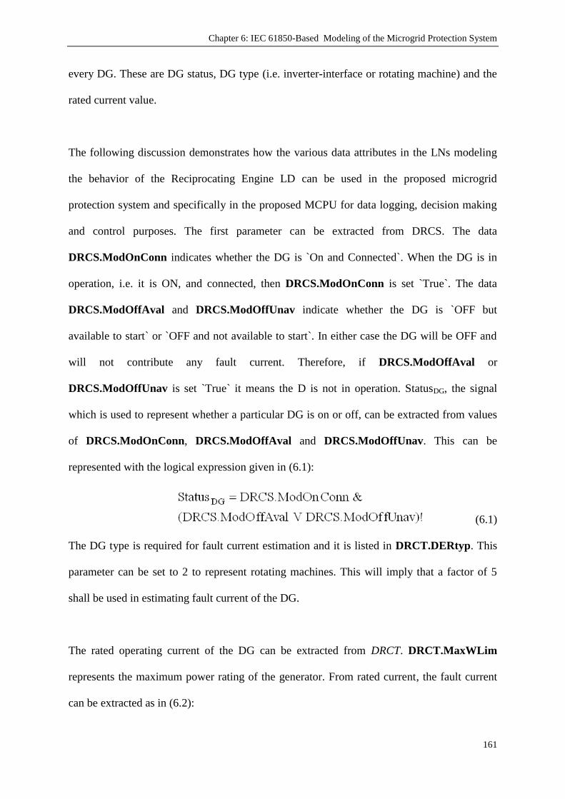
Chapter 6: IEC 61850-Based Modeling of the Microgrid Protection System
161
every DG. These are DG status, DG type (i.e. inverter-interface or rotating machine) and the
rated current value.
The following discussion demonstrates how the various data attributes in the LNs modeling
the behavior of the Reciprocating Engine LD can be used in the proposed microgrid
protection system and specifically in the proposed MCPU for data logging, decision making
and control purposes. The first parameter can be extracted from DRCS. The data
DRCS.ModOnConn indicates whether the DG is `On and Connected`. When the DG is in
operation, i.e. it is ON, and connected, then DRCS.ModOnConn is set `True`. The data
DRCS.ModOffAval and DRCS.ModOffUnav indicate whether the DG is `OFF but
available to start` or `OFF and not available to start`. In either case the DG will be OFF and
will not contribute any fault current. Therefore, if DRCS.ModOffAval or
DRCS.ModOffUnav is set `True` it means the D is not in operation. StatusDG, the signal
which is used to represent whether a particular DG is on or off, can be extracted from values
of DRCS.ModOnConn, DRCS.ModOffAval and DRCS.ModOffUnav. This can be
represented with the logical expression given in (6.1):
(6.1)
The DG type is required for fault current estimation and it is listed in DRCT.DERtyp. This
parameter can be set to 2 to represent rotating machines. This will imply that a factor of 5
shall be used in estimating fault current of the DG.
The rated operating current of the DG can be extracted from DRCT. DRCT.MaxWLim
represents the maximum power rating of the generator. From rated current, the fault current
can be extracted as in (6.2):

Chapter 6: IEC 61850-Based Modeling of the Microgrid Protection System
162
IfaultDG = (DRCT.MaxWLim/Voltage) * 5 (6.2)
Alternatively, DRAT block might be useful in supplying the fault current of the DG. The two
parameters DRAT.FltARtg and DRAT.MaxFltRtg represent the maximum fault and short
circuit currents supplied by the generator and they can be directly used by MCPU. The only
drawback is that these parameters are listed as `Optional` in the Logical Node, DRAT, and
they may be omitted for some models. The other parameters used above, on the other hand,
are all listed as `Mandatory` in their respective LN.
Figure 6.14 depicts the modeling of a Fuel Cell which is DG2 in the system. It also shows
how the various data, data attributes for a Fuel cell LD can be modeled using the LN models
defined in IEC 61850. The energy converter is modeled with DFCL, DSTK and DFPM. The
reason for having more than one LN for the same DG type is to control and model different
aspects of that particular DG.
Figure 6.14. Fuel Cell Modeling
For example in a fuel cell, DFCL has fuel cell characteristics which reflect those required for
remote monitoring of critical functions and states of the fuel cell. Since fuel cells are stacked
together to provide the desired voltage level, DSTK models the fuel cell stack characteristics
required for remote monitoring of the fuel cell stack. DFPM represents the fuel processing

Chapter 6: IEC 61850-Based Modeling of the Microgrid Protection System
163
module which is used to extract hydrogen from other types of fuels before the hydrogen is
used in a fuel cell to generate electricity.
ZBAT, ZBTC represent the battery, if any, used in the control and/or operation of the Fuel
cell. MFUL, DFLV represent the fuel characteristics and its delivery system.
CSWI and XCBR represent the DC switch between the fuel cell and the inverter. The inverter
which inverts DC input to AC output according to microgrid voltage and frequency
requirements and ensures synchronization is modeled with ZRCT and ZINV. ZRCT is used in
modeling rectifiers which converts generator output AC to intermediate DC. Properties can
be set in detail such as types of commutation, isolation, voltage regulation, conversion (AC-
DC, AC-AC-DC, AC-DC-DC), cooling method, AC system and filter types.
Furthermore, current and voltage limits can also be set. ZINV is used in modeling inverters
which converts DC input (either directly from a generator or intermediate DC fed by ZRCT)
to AC. Properties can be set in detail such as switch type, cooling method, type of
commutation, isolation, switching frequency and current connect mode. Furthermore, current
and voltage limits can also be set.
The remote control and communication module is exactly the same with reciprocating
engines. IHMI and ITCI provide a control interface while critical values are extracted from
DRCT and DRCS. DG status can be extracted similar to the logical expression given in (6.1).
The following discussion once again attempts to show how the various data and data
attributes in the Fuel Cell model relates to the developed communication-assisted protection
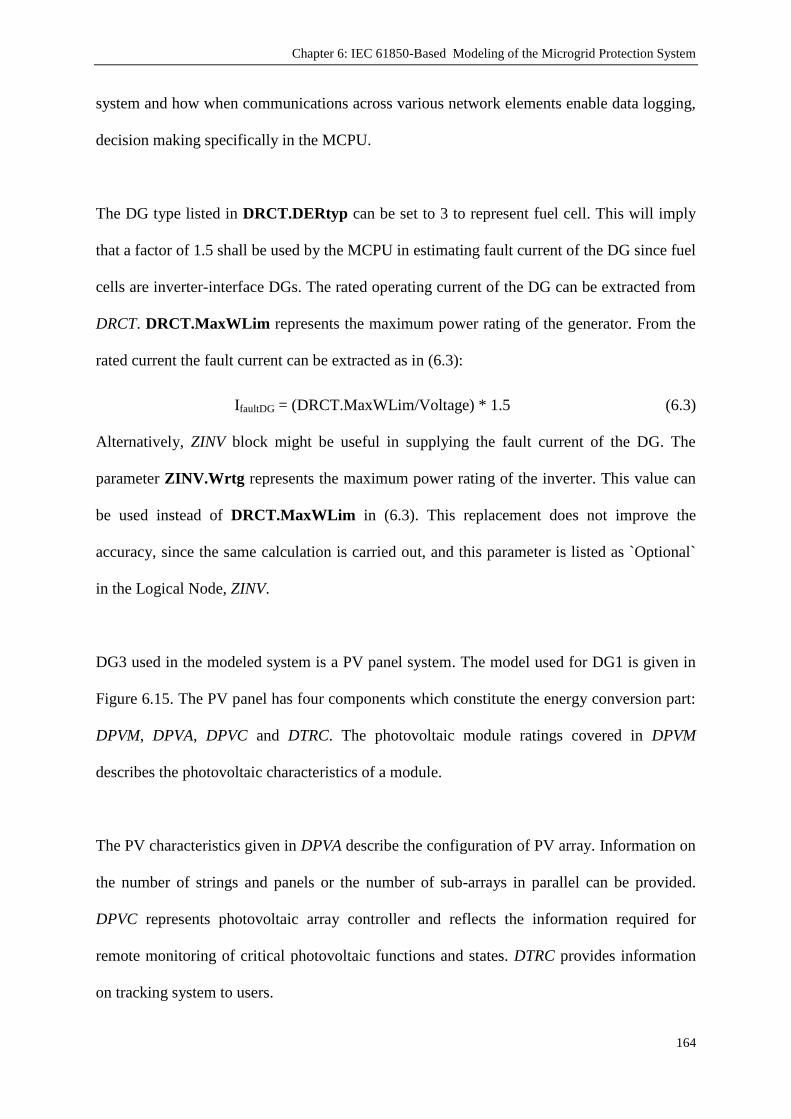
Chapter 6: IEC 61850-Based Modeling of the Microgrid Protection System
164
system and how when communications across various network elements enable data logging,
decision making specifically in the MCPU.
The DG type listed in DRCT.DERtyp can be set to 3 to represent fuel cell. This will imply
that a factor of 1.5 shall be used by the MCPU in estimating fault current of the DG since fuel
cells are inverter-interface DGs. The rated operating current of the DG can be extracted from
DRCT. DRCT.MaxWLim represents the maximum power rating of the generator. From the
rated current the fault current can be extracted as in (6.3):
IfaultDG = (DRCT.MaxWLim/Voltage) * 1.5 (6.3)
Alternatively, ZINV block might be useful in supplying the fault current of the DG. The
parameter ZINV.Wrtg represents the maximum power rating of the inverter. This value can
be used instead of DRCT.MaxWLim in (6.3). This replacement does not improve the
accuracy, since the same calculation is carried out, and this parameter is listed as `Optional`
in the Logical Node, ZINV.
DG3 used in the modeled system is a PV panel system. The model used for DG1 is given in
Figure 6.15. The PV panel has four components which constitute the energy conversion part:
DPVM, DPVA, DPVC and DTRC. The photovoltaic module ratings covered in DPVM
describes the photovoltaic characteristics of a module.
The PV characteristics given in DPVA describe the configuration of PV array. Information on
the number of strings and panels or the number of sub-arrays in parallel can be provided.
DPVC represents photovoltaic array controller and reflects the information required for
remote monitoring of critical photovoltaic functions and states. DTRC provides information
on tracking system to users.

Chapter 6: IEC 61850-Based Modeling of the Microgrid Protection System
165
.
Figure 6.15. PV Panel Modeling
ZBAT, ZBTC represent the battery, if any, used in the control and/or operation of the PV
arrays. As the PV panels solely depend on solar radiation there is no need for MFUL, DFLV
components as there is no fuel input. Similar to the fuel cell systems CSWI and XCBR
represent the DC switch between the PV arrays and the inverter. The inverter is, again,
modeled with ZRCT and ZINV.
The remote control and communication module is made up of IHMI and ITCI, as usual, and
provides a control interface while critical values are extracted from DRCT and DRCS. DG
status can be extracted similar to the logical expression given in (6.1). The DG type listed in
DRCT.DERtyp can be set to 4 to represent PV arrays. This will imply that a factor of 1.5
shall be used in estimating fault current of the DG since fuel cells are inverter-interface DGs.
The fault current contribution of the DG can be extracted from DRCT from
DRCT.MaxWLim as in (6.3). Alternatively, module short circuit current listed in DPVM,
i.e. DPVM.MdulSrtCctA, can be directly used by the MCPU instead of estimation. This
improves the accuracy however, the parameter DPVM.MdulSrtCctA is listed as `Optional`
in the Logical Node, DPVM and it might be omitted for some systems.

Chapter 6: IEC 61850-Based Modeling of the Microgrid Protection System
166
6.6. Data Maps With IEC 61850-7-420 Models
In order to substantiate the operation of the modeled blocks and the operation of the proposed
protection scheme, the system shown in Figure 6.16 is described over a predetermined
scenario. The discussion presented is aimed at showing how the communication of various
data should take place between various microgrid network elements to enable protection
related decision making, e.g. adjustment of the relay protection settings.
Figure 6.16. The system modeled according to IEC 61850-7-420
The system includes two inverter-interfaced DGs and a diesel generator DG which is used to
set the frequency and voltage under islanded conditions. The DGs are operated under
conventional droop control and share the loads in accordance with their capacities.
A specially designated scenario is applied to show different aspects of the protection scheme.
The applied scenario is as follows:

Chapter 6: IEC 61850-Based Modeling of the Microgrid Protection System
167
1. The system starts operation with full load, all DGs are on and the MG operates in
Grid-Connected Mode.
2. At t=0.2 sec a fault occurs in Load 1 (L1) and Circuit Breaker (CB) 2 opens. Due to
less power demand in the system DG1 also turned off.
3. At t=0.5 sec the utility grid experiences power outage for maintenance reasons and
MG becomes islanded.
4. At t=0.65 sec, while MG is operating in islanded mode another fault occurs in L4 and
CB8 opens.
5. At t=0.75 sec, the connection with the utility grid is restored and MG operates in grid-
connected mode.
6. At t=1 sec, the fault in L1 is cleared and it is reconnected to the system. Due to
increased power demand in the network DG1 is also put into operation.
7. At t=1.25 sec, a fault occurs in Load 5 and CB3 opens. To protect the integrity of the
microgrid, CB4 is closed and alternative path is used to energize right side of the
microgrid.
The system shown may assume different structures depending on the status of CB4 and CB5.
In the beginning CB4 is open and CB5 is connected. Therefore, the microgrid has two
branches in its structure. After t=1.25 sec, CB4 closes and CB3 opens. The microgrid
assumes a one-line structure. The changing selective levels of the relays are shown in the
tables given below. Comparing different selective level of a particular relay for different
microgrid structures shows the need for selectivity coordination. In literature, there are
algorithms to ensure dynamic relay hierarchy detection [182] and they will not be discussed
here.

Chapter 6: IEC 61850-Based Modeling of the Microgrid Protection System
168
As mentioned earlier, it is assumed that microgrid is sufficiently small and `k` is set to 1. This
means that DGs supply their maximum fault current for any fault. The parameters of the
network components used by the communication system are listed in Table 6.7.
TABLE 6.7. NETWORK COMPONENT PARAMETERS AT T=0 SEC
StatusDG DG type Ifault
DG1 DRCS.ModOnConn= True DRCT.DERtyp = 4 (DRCT.MaxWLim/Voltage) * 1.5
DG2 DRCS.ModOnConn= True DRCT.DERtyp = 3 (DRCT.MaxWLim/Voltage) * 1.5
DG3 DRCS.ModOnConn= True DRCT.DERtyp = 2 (DRCT.MaxWLim/Voltage) * 5
CB1 CB 2 CB 3 CB 4 CB 5 CB 6 CB 7 CB 8
XCBR.Pos ON ON ON OFF ON ON ON ON
Selective Level 1 2 2 N/A 3 3 4 4
The relay fault current value = Grid contribution + DG1 + DG2 + DG3
= IfaultGrid + (DG1.DRCT.MaxWLim/Voltage) * 1.5 + (DG2.DRCT.MaxWLim/Voltage)*1.5
+(DG3.DRCT.MaxWLim/Voltage)*5
At t=0.2 in line with the changes occurring in the microgrid, DG1 is turned off by the MCPU.
This happens by setting DG1.DRCS.ModOnConn false and DG1.DRCS.ModOffUnav
true. In order to achieve this, MCPU sends an IEC61850 compliant control message and asks
DG1 to switch off. When DG1 switches off, the DG1.DRCS.ModOnConn attribute changes
to FALSE and the DG1.DRCS.ModOffUnav attribute becomes TRUE. The change in data
parameters of the DG1 model is depicted in Figure 6.17:
MCPU -> DG1.IHMI -> DG1.ITCI -> DG1.DRCS -> DG1.DRCS.ModOnConn and ->
DG1.DRCS.ModOffUnav
Figure 6.17. Reporting DG status through IEC 61850-7-420 Models

Chapter 6: IEC 61850-Based Modeling of the Microgrid Protection System
169
At t=0.5 sec, the utility grid experiences power outage so the microgrid becomes islanded.
CB1 is now open. This information is extracted by the MCPU from the following scheme, as
shown in Figure 6.18. Relay1 controlling CB1 would send a GOOSE message to the MCPU
and the GOOSE message would contain the data attribute (Relay1.XCBR.Pos) beyond
others. The value of the attribute “Relay1.XCBR.Pos” was set in the relay to OFF an
indicator of the OPEN status of CB1. On receiving this GOOSE message from Relay1,
MCPU would unpack the contents of the GOOSE message, read the new status of CB1, and
adjust its “Network Component Parameter” table as shown in Table 6.8. Essentially, the
“Network Component Parameter” table has been updated to reflect the change in the status of
CB1.
MCPU -> Relay1.IHMI -> Relay1.ITCI -> Relay1.XCBR.Pos
Figure 6.18. Reporting Relay status through IEC 61850-7-420 Models
At t=0.5 sec the network component parameter table is as shown in Table 6.8.
TABLE 6.8. NETWORK COMPONENT PARAMETERS AT T=0.5 SEC
StatusDG DG type Ifault
DG1 DRCS.ModOffUnav = True DRCT.DERtyp = 4 (DRCT.MaxWLim/Voltage) * 1.5
DG2 DRCS.ModOnConn = True DRCT.DERtyp = 3 (DRCT.MaxWLim/Voltage) * 1.5
DG3 DRCS.ModOnConn = True DRCT.DERtyp = 2 (DRCT.MaxWLim/Voltage) * 5
CB1 CB 2 CB 3 CB 4 CB 5 CB 6 CB 7 CB 8
XCBR.Pos OFF OFF ON OFF ON ON ON ON
Selective Level N/A N/A 1 N/A 2 2 3 3
The relay fault current value = DG2 + DG3
= (DG2.DRCT.MaxWLim/Voltage)*1.5 - (DG3.DRCT.MaxWLim/Voltage)*5

Chapter 6: IEC 61850-Based Modeling of the Microgrid Protection System
170
At t=0.65 sec, a fault occurs in L4 and CB8 opens. In a similar fashion to Figure 6.18, MCPU
receives an IEC 61850 complaint packet and extracts this information:
MCPU -> Relay8.IHMI -> Relay8.ITCI -> Relay8.XCBR.Pos
At t=0.75 sec, the connection is restored with the utility and once again, the microgrid
operates in grid-connected mode. This information is extracted by the MCPU from:
MCPU -> Relay1.IHMI -> Relay1.ITCI -> Relay7.XCBR.Pos
At t = 1 sec, L1 and DG1 are connected to microgrid. These will be reported to MCPU
through:
MCPU -> Relay2.IHMI -> Relay2.ITCI -> Relay2.XCBR.Pos
and
MCPU -> DG1.IHMI -> DG1.ITCI -> DG1.DRCS -> DG1.DRCS.ModOnConn and ->
DG1.DRCS.ModOffUnav
Finally, at t = 1.25 sec, L5 and CB3 are disconnected from and CB4 is connected to
microgrid. These will be reported to MCPU through following channels:
MCPU -> Relay3.IHMI -> Relay3.ITCI -> Relay1.XCBR.Pos
MCPU -> Relay4.IHMI -> Relay4.ITCI -> Relay4.XCBR.Pos
The final state of the network component table is as shown in Table 6.9.
TABLE 6.9. NETWORK COMPONENT PARAMETERS AT T=1.25 SEC
StatusDG DG type Ifault
DG1 DRCS.ModOnConn = True DRCT.DERtyp = 4 (DRCT.MaxWLim/Voltage) * 1.5
DG2 DRCS.ModOnConn = True DRCT.DERtyp = 3 (DRCT.MaxWLim/Voltage) * 1.5
DG3 DRCS.ModOnConn = True DRCT.DERtyp = 2 (DRCT.MaxWLim/Voltage) * 5
CB1 CB 2 CB 3 CB 4 CB 5 CB 6 CB 7 CB 8
XCBR.Pos ON ON OFF ON ON ON OFF ON
Selective Level 1 2 N/A 3 3 4 5 5
The relay fault current value = Grid contribution + DG1 + DG2 + DG3
= IfaultGrid + (DG1.DRCT.MaxWLim/Voltage) * 1.5 + (DG2.DRCT.MaxWLim/Voltage)*1.5
+(DG3.DRCT.MaxWLim/Voltage)*5

Chapter 6: IEC 61850-Based Modeling of the Microgrid Protection System
171
For all of the changes occurring in the microgrid, MCPU re-calculates the fault current. These
new values are updated in the associated relays through the communication shown in Figure
6.19. MCPU would essentially send an IEC 61850 compliant control message to the Relay.
On receiving and unpacking the control message, Relay finds out that it needs to reset its
Relay.PTOC.StrVal attribute to reflect the changes that have occurred.
MCPU -> Relay.IHMI -> Relay.ITCI -> Relay.PTOC -> Relay.PTOC.StrVal
Figure 6.19. Updating Relay operating Currents through IEC 61850-7-420 Models
Over an established communication line between the components and the MCPU, the
proposed protection scheme works perfectly with the models that are designed in compliance
with IEC61850 and IEC 61850-7-420.
6.7. Conclusion
Microgrids have dynamic structures which change more often than the conventional large
networks. In order to ensure protection under these conditions, a centralized management is
required to monitor and communicate with the microgrid components and assign suitable
operation parameters. The communication lines and systems inevitably utilized in microgrids
require standardization so that equipment with different manufacturers or owners can work
together; and new deployments can be easily done. Design of a central microgrid
management system will be very much simplified if all of the components use the same
communication standard. Therefore, communication standards such as IEC 61850 and the

Chapter 6: IEC 61850-Based Modeling of the Microgrid Protection System
172
extension IEC 61850-7-420, which is aimed at modeling the information exchange for DER
devices, have been published.
In the research project presented in this thesis, two important extensions have been made to
IEC 61850 Standard. Due to its promising nature for future control systems, an extension has
been made for FCL to facilitate its modeling. Another extension has been made for EVs since
the availability of the technologies required and the higher efficiency of electric-driven cars
create a genuine interest for EVs in the market. The large acceptance of EVs will definitely
have impacts on electrical networks because through V2G technology, EVs not only draw
power from the network but also act as distributed storage devices. With these extensions, the
mentioned communication standard has been made more comprehensive.
Finally, the information models of the various network elements and their modeling as per
IEC 61850 and its most recent extension, i.e. IEC61850-7-420 have been described. The
presented relay and DG information models are standard and can be used for modeling the
data exchange in any power system network. The universal modeling of information/data
models in DGs regardless of their models and manufacturers is very important for having a
universal concept for standardizing the data to be communicated within electrical networks
for automation, control and data logging purposes. This is the fundamental for the
implementation of plug and play concept in microgrids.
The work presented in this chapter has made a very significant contribution to knowledge by
demonstrating how a microgrid protection system can be modeled in accordance with the
international communication standard the IEC 61850 and its recent extension IEC 61850-7-
420. Sample Data Maps are illustrated on a predetermined scenario which highlights different

Chapter 6: IEC 61850-Based Modeling of the Microgrid Protection System
173
aspects of the developed protection scheme. The details of simulation works are given in the
next chapter.

Chapter 7: Microgrid Operation and Protection Simulations
174
Chapter 7
Microgrid Operation and Protection Simulations
Publications pertaining to this chapter:
1) Taha Selim Ustun, Cagil Ozansoy, Aladin Zayegh, "Simulation of Communication Infrastructure of a
Centralized Microgrid Protection System Based on IEC 61850-7-420", in Proceedings of Third IEEE
International Conference on Smart Grid Communications (SmartGridComm), Tainan City, Taiwan, 5-8
Nov, 2012.
2) Taha Selim Ustun, Cagil Ozansoy, Aladin Zayegh, "Investigation of Micro-Grid Behavior While
Operating Under Various Network Conditions", in Proceedings of IEEE International Conference on
Smart Grid Engineering (SGE’12), UOIT, Oshawa, Canada, 27-29 August, 2012
7.1. Introduction
Preceding chapters have presented the novel microgrid protection scheme developed during
the course of this research. Chapter 2 discussed the microgrid concepts and fundamentals
from a number of aspects. Chapter 3 outlined how a conceptual microgrid case study was
developed. Chapter 4 investigated the use of OO modeling of microgrid systems. Chapter 5
discussed the development of an adaptive relay protection parameter assignment logic.
Chapter 6 explored the modeling of microgrid communications as per the IEC61850
standard. This chapter gives the details of the simulation works undertaken to validate and
confirm the intellectual contributions made in the preceding Chapters.

Chapter 7: Microgrid Operation and Protection Simulations
175
Firstly, general microgrid simulations have been performed to investigate the microgrid
behavior under various conditions. Microgrid – utility grid connection has been switched on
and off to examine the differences between grid-connected and islanded operation modes.
Utility grids with different sizes have been implemented to emulate the impacts of the
microgrid connections within transmission and distribution networks. Furthermore, the
dynamic nature of the microgrids has been reflected by changing the structure of the
connections and analyzing the power flow in the system.
Due to their promising potential in the car market, EVs have also been considered in these
microgrid simulations to investigate the effect of Vehicle-to-Grid (V2G) and Grid-to-Vehicle
(G2V) technologies on current microgrids. The same microgrid structure has been utilized
with the initial topology used for microgrid behavior investigations to be able to contrast the
results.
Following these investigative simulations, the protection scheme proposed in the preceding
chapters has been implemented for further verification. The individual control and
communication blocks of the proposed communication-assisted protection scheme have been
modeled and simulated for various microgrid events. Control signals have been named in
accordance with IEC 61850 standard and its recent extension IEC 61850-7-420. The results
show that the modeling, control signals and the adaptation of the protection system to the
changes in the microgrid are satisfactory.
In conclusion, the simulation works have been performed over a wide range of topologies and
operating conditions. The results have shown that the preliminary assumptions made during
the design of this adaptive microgrid protection system were factual and the overall design

Chapter 7: Microgrid Operation and Protection Simulations
176
successfully serves to adjust this protection system according to the events occurring in the
microgrid.
7.2. Microgrid Operation Simulations
To understand the behavior of micro-grids when operated in grid connected and islanded
modes, it was necessary to build a model micro-grid network and conduct in depth studies
and simulations using this model to determine its operational behavior. All modeling and
simulations presented in this section have been achieved through utilizing the Paladin
DesignBase 4.0 software suite.
The micro-grid layouts used for the simulations are typical in nature [73, 90, 151, 153, 182].
The overall structures of the micro-grids used in simulations are depicted in Figure 7.1 and
7.2. Both systems are identical in all ways except for the bus tie that connects Bus 4 to the
upstream system. The connection supply connection for BUS 4 is fed through CB5 in Figure
7.1 and CB12 in Figure 7.2.
Figure 7.1. Micro-grid network structure used for investigation & simulation
– when bus 4 is connected to bus 3 through CB5

Chapter 7: Microgrid Operation and Protection Simulations
177
The two similar yet different layouts represent a dynamic change in a micro-grid network
structure and can be viewed as two possible ways of connecting BUS 4 to the micro-grid. The
reason for testing and simulating two micro-grid structures is that in the event of a fault or
maintenance being done to/at CB5 for example, CB12 would become the feeder supply line
to BUS 4 ensuring reliability of supply. The two networks behave in different ways by
altering the path which power flows to/from different areas of the network. The impact of this
will be further elaborated in the following sections.
Figure 7.2. Micro-grid network structure used for investigation & simulation
– when bus 4 is connected to bus 2 through CB12
The micro-grid consists of varying loads and DG sources connected to a low voltage (LV) -
480V network. The loading scheme for the networks is shown in Table 7.1.
TABLE 7.1 – MICRO-GRID LOADING MAGNITUDES
Name Magnitude
MW MVAR
Load 1 3.5 0.25
Load 2 1.4 0.25
Load 3 2 0.25

Chapter 7: Microgrid Operation and Protection Simulations
178
The loads within the micro-grids are placed close to the DG sources to minimize the power
loss during transmission. The micro-grids consist of 2 primary radial feeders and 2 secondary
feeders connected through various circuit breakers (see Figure 7.1 & 7.2). BUS 1 of the
micro-grid is coupled to the main medium voltage (MV) utility grid through a transformer
and a circuit breaker. This connection is elaborated on further in Section 7.2.1. This circuit
breaker is operated to connect/disconnect the micro-grid to/from the utility bus, while the
feeding circuit breakers CB1, CB2, CB5, CB6 and CB12 are operated to isolate a section or
multiple sections within the micro-grid.
The wind generation micro-source (DG1 connected to BUS 2) has been modeled using a
standard diesel generator. The reason for using a diesel generation in the model for wind
generation is that wind generation uses rotating machines much like diesel generators. This
provides us with although not an exact model of wind turbine generation, but a close
approximation, which is sufficient enough to observe its behavior.
The final DG source (DG4) is a fuel cell which has been modeled using a PV cell source. The
decision to use a PV panel model was made due to the fact that both PV panel and fuel cells
are inverter interfaced-DGs (IIDG). Their behaviors under normal operation as well as fault
conditions are very similar. Therefore, the used model provides a close approximation of
operation of a DG fuel cell micro-source. Table 7.2 shows the full list of all the distributed
generation sources of the micro-grid network and their magnitudes.
TABLE 7.2 – DISTRIBUTED GENERATION TYPE & MAGNITUDE OF POWER GENERATED
Component Name Type of Generation Magnitude(MW)
DG1 Wind 2.00
DG2 Solar(PV) 1.00
DG3 Diesel 2.00
DG4 Fuel Cell 1.00

Chapter 7: Microgrid Operation and Protection Simulations
179
7.2.1. Microgrid Simulation - Islanded Operation
Operation in Islanded mode is achieved when the Circuit Breaker 0 (CB0) is opened,
disconnecting the micro-grid from the main grid. When operated in Islanded mode the micro-
sources are responsible for maintaining the voltage and frequency while sharing the power
supply to the loads [211]. The diesel generator, namely DG3, serves to maintain the
frequency of the network in absence of the utility network. It also provides reactive power
along with wind farm, DG1, which cannot be supported by IIDGs, DG2 and DG4 [14]. This
fact becomes evident when it is observed that the micro-grids as a whole are very self
sufficient and self reliant.
Although greater currents are present throughout the micro-grid during islanded operation,
the power supply demands of the various loads of the micro-grid are met by the power
supplied from distributed generation micro-sources within the network. The power supplied
to the various loads is faultless and the network is stable. This enables the micro-grid to have
a “plug and play” functionality which provides a solution for constant power supply demands
in the case of larger/main network faults and/or disturbances.
However, though stable as a whole, the micro-grid branches connected through BUS 1 (CB1
& CB2) are closely dependent on each other to supply sufficient power and maintain stable
operation when operated in islanded mode. The branches connected through BUS 3 (CB5 &
CB6 – in configuration 1) are also dependant on one another. This can be traced back to the
micro-grid acting as a single entity.

Chapter 7: Microgrid Operation and Protection Simulations
180
When the operational behaviors of the two micro grids depicted in Figure 7.1 and 7.2 are
observed, it can be seen that the currents present in the two primary feeder branches (CB1 &
CB2) in Figure 7.2 configurations are significantly higher than those present in that of Figure
7.1. This can be seen in the tabulated branch flow results below in Table 7.3 and Table 7.4.
This difference in current flow leads to the conclusion that the primary feeder branches in
Configuration 2 are much more dependent on the power supplied to/from each other than
those in Configuration 1. This greater dependence makes this section more important in case
of a critical fault within the micro-grid.
TABLE 7.3 – ISLANDED OPERATION: MICRO-GRID CONFIGURATION 1 - BRANCH FLOW RESULTS
Name To Current (Amps) Power (MW)
BUS 1 BUS 2 866 0.60
BUS 3 865 -0.60
BUS 2 LOAD 1 4227 3.50
DG1 (WIND) 3585 -2.91
BUS 3 BUS 4 568 0.40
BUS 5 1432 -1.00
BUS 4 DG2 (SOLAR) 1345 -1.00
LOAD 2 1712 1.40
BUS 5
LOAD 3 2426 2.00
DG3 (DIESEL) 2479 -2.00
DG4 (FUEL CELL) 1209 -1.00
TABLE 7.4 – ISLANDED OPERATION: MICRO-GRID CONFIGURATION 2 - BRANCH FLOW RESULTS
Name To Current (Amps) Power (MW)
BUS 1 BUS 2 1200 0.99
BUS 3 1202 -1.00
BUS 2
LOAD 1 4238 3.51
DG1 (WIND) 3511 -2.91
BUS 4 0.40 569
BUS 3 BUS 5 1202 -1.00
BUS 4 DG2 (SOLAR) -1.00 -1.00
LOAD 2 1714 1.40
BUS 5
LOAD 3 2431 2.00
DG3 (DIESEL) 2406 -2.00
DG4 (FUEL CELL) 1220 -1.00
7.2.2. Grid-Connected Simulation: Transmission Network Connection, IEEE T14-Bus
System
The decision to model and simulate the connection of the micro-grids to the T14-Bus as well
as the 34-Bus system was made with the intention of observing the behavior of the micro-

Chapter 7: Microgrid Operation and Protection Simulations
181
grids when connected to different networks which operate with differing purposes, i.e.
transmission and distribution. The two networks also present two different system voltage
levels. The T14 Bus system has a voltage of 69kV (MV) while the 34-Bus system has a
voltage of 24.9kV (LV). See Appendix – A for parameters of IEEE T14-Bus test system.
The T14 Bus system configuration is typically employed at the transmission level power
supply and when either structure of the micro-grid (Figure 7.1 or 7.2) is connected to the
main medium voltage (MV – 69kV) busbar of the T14 Bus system both micro-grid structures
result in acting as a net load to the main network. Pictured in Figure 7.3 is the T14 bus system
with the connection point for the micro-grid(s) outlined. It should be noted that this is a
schematic representation of the standard T14 Bus system with an arrow indicating where the
micro-grid configuration 1 is connected to it.
As mentioned previously, the loading schemes employed by both of the micro-grid
Configurations 1 & 2 are the same and the amount of power export from the main grid to the
micro-grid is approximately 0.9 MW. The added power provided by the grid significantly
reduces the amount of power needed to be supplied by some of the DG sources within the
micro-grid structure. This reduces the stress placed upon the DG micro-sources when
compared with the islanded-operation of the micro-grid.
With the addition of the utility bus as another source of power to supply the micro-grid, the
dependence on power to be supplied from neighboring branches within the micro-grid
structure is alleviated. Furthermore, unlike islanded operation, the duty of maintaining the
network frequency is fulfilled by the utility network rather than DG3. The removal of the
dependence on power supplied from DG sources within the micro-grid improves the system

Chapter 7: Microgrid Operation and Protection Simulations
182
stability and system fault response. This improvement in stability is the result of the micro-
grid being able to be segmented into sections in the event of a fault.
Figure 7.3. IEEE Standard T14 Bus System [212] with Microgrid Connection

Chapter 7: Microgrid Operation and Protection Simulations
183
The segmented area/zone is then able to supply its loading power demands load from the DG
source(s) within its own area/zone. In this fashion, the micro-grid can be said to be acting as a
small branching radial network which can function even after being sectionalized from a
primary/key busbar within the micro-grid.
TABLE 7.5 – GRID CONNECTED OPERATION: T14 BUS SYSTEM - MICRO-GRID CONFIGURATION 1
POWER FLOW RESULTS
Name To Current (Amps) Power (MW)
BUS 1
UTILITY GRID 1109 -0.91
BUS 2 1835 1.50
BUS 3 727 -0.60
BUS 2 LOAD 1 4228 3.50
DG1 (WIND) 2481 -2.00
BUS 3 BUS 4 569 0.40
BUS 5 1270 -1.00
BUS 4 DG2 (SOLAR) 1345 -1.00
LOAD 2 1712 1.40
BUS 5
LOAD 3 2426 2.00
DG3 (DIESEL) 2479 -2.00
DG4 (FUEL CELL) 1298 -1.00
TABLE 7.6 – GRID CONNECTED OPERATION: T14 BUS SYSTEM - MICRO-GRID CONFIGURATION 2
POWER FLOW RESULTS
Name To Current (Amps) Power (MW)
BUS 1
UTILITY GRID 1109 -0.91
BUS 2 2371 1.91
BUS 3 1270 -1.00
BUS 2
LOAD 1 4229 3.50
DG1 (WIND) 2481 -2.00
BUS 4 569 0.40
BUS 3 BUS 5 1270 -1.00
BUS 4 DG2 (SOLAR) 1346 -1.00
LOAD 2 1713 1.40
BUS 5
LOAD 3 2426 2.00
DG3 (DIESEL) 2479 -2.00
DG4 (FUEL CELL) 1298 -1.00
When contrasted with the micro-grid being operated in islanded mode, there is a reduction in
neighboring DG power supply dependence. This results in an increase in power flowing
through some of the feeders of the network, while there is a decrease in others. This change
in power flow can be directly related to the ampacity requirements of the feeder lines. When
the operation of the two micro-grid configurations are separately connected the main grid and
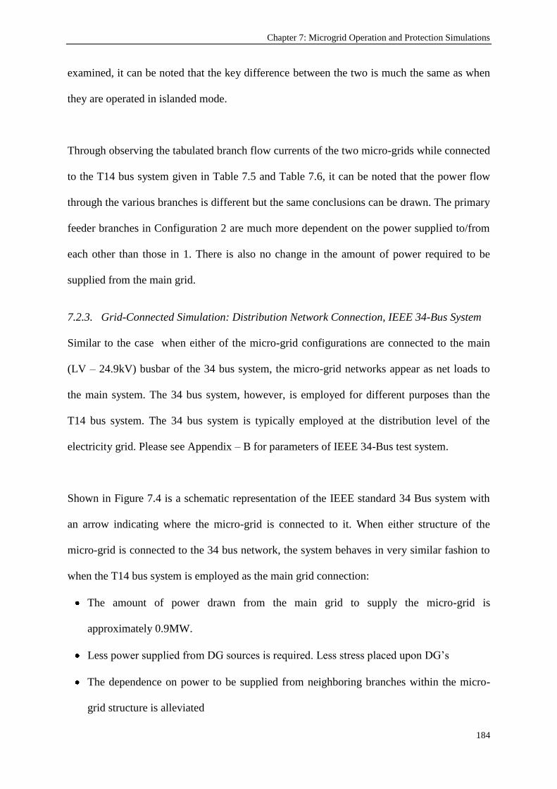
Chapter 7: Microgrid Operation and Protection Simulations
184
examined, it can be noted that the key difference between the two is much the same as when
they are operated in islanded mode.
Through observing the tabulated branch flow currents of the two micro-grids while connected
to the T14 bus system given in Table 7.5 and Table 7.6, it can be noted that the power flow
through the various branches is different but the same conclusions can be drawn. The primary
feeder branches in Configuration 2 are much more dependent on the power supplied to/from
each other than those in 1. There is also no change in the amount of power required to be
supplied from the main grid.
7.2.3. Grid-Connected Simulation: Distribution Network Connection, IEEE 34-Bus System
Similar to the case when either of the micro-grid configurations are connected to the main
(LV – 24.9kV) busbar of the 34 bus system, the micro-grid networks appear as net loads to
the main system. The 34 bus system, however, is employed for different purposes than the
T14 bus system. The 34 bus system is typically employed at the distribution level of the
electricity grid. Please see Appendix – B for parameters of IEEE 34-Bus test system.
Shown in Figure 7.4 is a schematic representation of the IEEE standard 34 Bus system with
an arrow indicating where the micro-grid is connected to it. When either structure of the
micro-grid is connected to the 34 bus network, the system behaves in very similar fashion to
when the T14 bus system is employed as the main grid connection:
The amount of power drawn from the main grid to supply the micro-grid is
approximately 0.9MW.
Less power supplied from DG sources is required. Less stress placed upon DG‟s
The dependence on power to be supplied from neighboring branches within the micro-
grid structure is alleviated

Chapter 7: Microgrid Operation and Protection Simulations
185
Increased network stability in the event of fault within the micro-grid.
The primary feeder branches in configuration 2 are much more dependent on the power
supplied to/from each other than those in 1.
There is also no change in the amount of power required to be supplied from the main
grid when switching between configurations.
Figure 7.4. IEEE Standard 34 Bus System [213] with Microgrid Connection
This is confirmed when a comparison is made between the power flow results of the T14 bus
system given in Table 7.5 & 7.6 and the 34 bus system given in Table 7.7 & 7.8.

Chapter 7: Microgrid Operation and Protection Simulations
186
Nevertheless, there is one minor difference between the network behaviors observed in the
simulations. When either structure of the micro-grid is connected to the 34 bus system, the
amount of power which is sourced from the grid is the same as the T14 bus system. However,
due to the standard default setup of the bus voltages at 0.5kV in the 34 bus system and the
T14 being 480V for the LV level (0.48kV) the current flowing is slightly altered in CB1 &
CB3 feeders, despite the power flowing remaining the same.
TABLE 7.7 – GRID CONNECTED OPERATION: IEEE STANDARD 34 BUS SYSTEM - MICRO-GRID CONFIGURATION 1
POWER FLOW RESULTS
Name To Current (Amps) Power (MW)
BUS 1
UTILITY GRID 1303 -0.91
BUS 2 1836 1.50
BUS 3 827 -0.60
BUS 2 LOAD 1 4229 3.50
DG1 (WIND) 2481 -2.00
BUS 3 BUS 4 569 0.40
BUS 5 1206 -1.00
BUS 4 DG2 (SOLAR) 1345 -1.00
LOAD 2 1712 1.40
BUS 5
LOAD 3 2427 2.00
DG3 (DIESEL) 2413 -2.00
DG4 (FUEL CELL) 1345 -1.00
TABLE 7.8 – GRID CONNECTED OPERATION: IEEE STANDARD 34 BUS SYSTEM - MICRO-GRID CONFIGURATION 2
POWER FLOW RESULTS
Name To Current (Amps) Power (MW)
BUS 1
UTILITY GRID 1303 -0.91
BUS 2 2371 1.91
BUS 3 1206 -1.00
BUS 2
LOAD 1 4230 3.50
DG1 (WIND) 2482 -2.00
BUS 4 569 0.40
BUS 3 BUS 5 1206 -1.00
BUS 4 DG2 (SOLAR) 1346 -1.00
LOAD 2 1714 1.40
BUS 5
LOAD 3 2427 2.00
DG3 (DIESEL) 2413 -2.00
DG4 (FUEL CELL) 1345 -1.00
Again much like the T14 grid connected configuration, when the 34 bus grid connected
system is contrasted with the micro-grid operating is islanded mode; there is a reduction in
the neighboring DG power supply dependence. This results in an increase in power flowing

Chapter 7: Microgrid Operation and Protection Simulations
187
through some of the feeders of the network, while there is a decrease in others. This change
in power flow can be directly related to the ampacity requirements of the feeder lines.
7.2.4. Microgrid V2G-G2V Simulations for EV (Charging/Supplying)
Various simulations works have been performed to analyze the impact of possible EV
migration on electrical networks. Paladin Design Base 4.0 software package was utilized to
model the components as well as the networks. Considering a typical neighborhood, thirty
“Chevrolet- Volt” EVs using Level 2a [134] charging option were taken as basis for
simulation works.
V2G-G2V, i.e. vehicle-to-grid and grid-to-vehicle, cases are examined by modeling EVs as
power sources in the prior case and as loads in the latter. For the sake of simplicity, the
charging and discharging characteristics of the EV batteries are assumed to be regular. The
microgrid system is connected to IEEE T14-bus system and IEEE 48 Bus system, shown
above in Figure 7.3 and Figure 7.4, respectively, to investigate the behavior of the microgrid
during V2G implementation.
Figure 7.5. The Sample Microgrid with EV deployments (G2V mode – charging)

Chapter 7: Microgrid Operation and Protection Simulations
188
Figure 7.5 shows the sample microgrid utilized in earlier simulations with EV connection. In
this figure, the operation mode of EV is charging, i.e. G2V. The connection has been
performed in the lowest level of distribution as this will be the case in real-life
implementations where EVs will be charged for the houses of the owners. Figure 7.6 shows
when the EVs are used as power sources and, through V2G technology, they are supplying
power to the grid.
Figure 7.6. The Sample Microgrid with EVs operating in V2G mode
The simulation results are summarized in Table 7.9 below. Various parameters are tabulated
under operation without any EV connection and operations under V2G (EV supplying power)
and G2V (EV charging) conditions.
As mentioned in the literature [141, 143, 209], EV connection does not have any major
impact in either of the Bus Systems utilized. This shows that V2G technology does not
constitute a significant problem at transmission level. However, this does not hold for
distribution networks. When the impact of the EVs on the sample microgrid is analyzed, it is

Chapter 7: Microgrid Operation and Protection Simulations
189
clear that large scale mitigation to EV technology requires some developments at distribution
networks, their management and protection. Once this challenge is managed, electrical
networks can enjoy the benefits of new generation EVs.
TABLE 7.9 – SIMULATION RESULTS FOR TEST CASES
Islanded Operation IEEE T14 Bus IEEE 34 BUS
Control
Parameter V2G G2V V2G G2V V2G G2V
VBus1 479.52 V 479.328 V 479.6 V 496.3V 479.6V 479.7 V
VBus4 479.76 V 479.424 V 479.8 V 496.4 V 479.8 V 479.5 V
VBus5 479.81 V 479.664 V 479.8 V 496.5 V 479.8 V 479.8 V
IBus1-Bus2 1836 A 1836.9 A 1835.4 A 1777.3 A 1835.4 A 1835.2 A
IBus1-Bus3 -1836.3 A -1837.2 A -1216.8 A -1296 A -1209.8A -769.1
IGrid-Bus1 N/A N/A 4.3 A 13.23 A 14.7 A 27.8 A
IEV -481.3A 120.4 A -481.2 A 113.67 A -481.2 A 120.3 A
IDG3 -2579.5 A -2483 A -1821.4A -1833.1 A -1805.6 A -1808.1 A
IDG1 -2481.8 A -3731.7 A -2481 A -2392. A -2481 A -2480.8 A
Furthermore, a careful analysis yields that the presence of EVs in the electrical network
changes the flowing currents in the system. During G2V mode EVs are acting as loads and
drawing current from the network. Since higher operating currents are expected, relays are
supposed to be programmed accordingly. In contrast, during V2G operation, the current
provided by EV contributes to a possible fault and that shall be taken into account by the
MCPU. In parallel with these deductions, the developed protection system is equipped with
necessary infrastructure and modeling (EV modeling with IEC 61850-7-420) to provide the
much required reliable and safe operation. Any other storage device can also be handled like
EVs where the storage device can supply or draw power from the network.
7.3. Fault Parameter follow-up for Microgrid Operation Simulations
Fault current analyses performed for different networks, which are presented in Appendix –
C, clearly show that the fault levels vary for each operation setup and, therefore, shall be
monitored. In order to test the developed fault parameter adjustment procedure in relation to

Chapter 7: Microgrid Operation and Protection Simulations
190
the changes occurring in the microgrid, the developed scheme has been modeled by using the
MATLAB/Simulink computing software. The parameters which are introduced and explained
in Chapter 5 have been implemented in these simulation studies. Initially, relays and
distributed generators were re-modeled by equipping them with communication modules
which are essential for the realization of the proposed scheme. Figure 7.7 shows the new
model designed for relays whereas Figure 7.8 shows the Communication and Control Module
(CCM) in detail.
Figure 7.7. Relay model with Communication Module
Figure 7.8. Relay Communication and Control Module
Three different signals are fed to the communication and control module:
Time delay is the amount of delay applied for the realization of selectivity between
relays.

Chapter 7: Microgrid Operation and Protection Simulations
191
`Tripping Current` signal is the updated fault current signal which is calculated by the
MCPU.
Relay Current is the current which flows through the relay.
Time delay can be determined in two different ways. Firstly, depending on the microgrid
structure suitable time delays for selectivity can be calculated and embedded in the CCM.
Alternatively, the selectivity can also be calculated by the MCPU on the fly and fed to the
relays. This feature will make the system very versatile and new connections can be
performed easily. The anticipated drawback is the design and implementation of an
appropriate algorithm which can analyze the current status of the network and assign
incremental time delays to the relays.
The CCM compares the two current values, i.e. `Tripping Current` and `Relay Current` and
sets `Fault Detection` Signal if the latter is larger. The tripping signal is delayed for the
interval defined by `time delay`. If after this delay the fault has not been cleared by any other
Relay (which has a higher priority), `Trip Signal` will be set to open the circuit.
For a proper communication to be achieved in the network DGs need to be equipped with a
communication module which will report the parameters such as status, rated current, DG
type and the coefficient k to the MCPU. For example, this can be achieved by mapping them
into GOOSE and other IEC 61850 compliant messages as explained in Chapter 6. Figure 7.9
shows the new DG model with communication module.
`Status` signal indicates whether DG is in operation, `Irated` is the rated current of the DG
and `DG type` indicates whether this particular DG is an inverter interfaced DG such as a PV
panel or a rotating machine such as a diesel generator. The fault current is calculated from

Chapter 7: Microgrid Operation and Protection Simulations
192
Irated and DG type signals then in accordance with the Status signal the fault current is
included in or excluded from the Tripping Current.
Figure 7.9. DG with Communication Module
The last signal `k` is a unique contribution to knowledge in this research and aimed at making
the model more realistic. The signal `k` is the coefficient between 0 and 1 which designates
the impact amount of the DG on each Relay. The DG supplies a maximum fault current of
IfaultDG. However, this current may decrease if the fault occurs farther away from the DG due
to cable impedance. That is to say any particular DG will have different `k` values for every
relay in the network.
The relays closer to the DG under consideration will have higher `k` levels whereas those
which are farther downstream or upstream will have lower coefficients. The coefficient has
two indices such as `k12` which means the `the fault current coefficient of DG1 for Relay 2`.
The MCPU shall use relative `k` values while calculating relays‟ tripping currents. In this
way not only the effect of distribution lines is taken into account but also a more flexible and
versatile protection system is designed. This is especially desirable for growing networks
with potential new deployments.

Chapter 7: Microgrid Operation and Protection Simulations
193
In short, DG communication module calculates the maximum fault current, IfaultDG, according
to the assumption that in case of a fault inverter interfaced and rotating machine DGs supply
1.5 and 5 times their rated currents, respectively. It supplies four signals to MCPU which are
Status, Irated, IfaultDG and k values. The MCPU which is responsible of calculation of tripping
currents, time delays (optional) and updating of relay operating points is designed for a
sample system with three DGs and five Relays.
Figure 7.10. MCPU Block (inside)
In addition to incoming signals for DGs, MCPU also receives signals Grid‟s fault
contribution (IfaultGRID) and the operating mode of the microgrid, i.e. grid-connected or
islanded mode of operation. For each relay, every DG‟s fault contribution is calculated as
explained in Chapter 5. Then the fault current levels are updated to the respective relay to
ensure proper operation and sufficient protection.

Chapter 7: Microgrid Operation and Protection Simulations
194
The inner view of MCPU is shown in Figure 7.10. The status and rated current signals are
directed to the data map block. These values are stored in a table for monitoring the current
status of the network. They can also be used for further processing such as in fault isolation
algorithms or for service quality enhancement in combination with the power management
system.
The strength of this design is in its ability to accept new connections with very simple
modifications. This is an invaluable feature since, when combined with the new relay and
distributed generator designs, it introduces plug-and-play concept to electrical networks from
electrical point of view. In the MCPU shown, for instance, a new connection of DG will only
require an additional input to `Tripping Current Calculator` and `Data MAP` blocks. New
DG‟s fault current contribution will be taken into account automatically. Similarly,
connection of a new relay (e.g. which connects a load to the system) can be realized with an
additional calculation step and an output in `Tripping Current Calculator`. Unlike the former
step, this one requires an additional work to determine the coefficient `k` for each DG.
7.3.1. MATLAB Simulation Results
In order to substantiate the operation of the designed blocks and the proposed protection
scheme, the microgrid model shown in Figure 7.11 has been simulated. The system includes
two inverter-interfaced DGs and a diesel generator DG which is used to set the frequency and
voltage under islanded conditions. The DGs are operated under conventional droop control
and share the loads in accordance with their capacities.
A specially designated simulation scenario has been developed and applied to show different
aspects of the protection scheme. The applied scenario is as follows:

Chapter 7: Microgrid Operation and Protection Simulations
195
1. The system starts operation with full load, all DGs are on and the microgrid operates in
Grid-Connected Mode.
2. At t=0.2 sec Load1 turns off and R3 opens. Due to less power demand in the system
DG1 also turns off.
3. At t=0.5 sec the utility grid experiences power outage for maintenance reasons and
microgrid becomes islanded.
4. At t=0.65 sec, while microgrid is operating in islanded mode a fault occurs in Load4
and R7 opens.
5. At t=0.75 sec, the connection with the utility grid is restored and microgrid operates in
grid-connected mode.
6. At t=1 sec, Load1 is reconnected to the system. Due to increased power demand in the
network DG1 is also put into operation.
Figure 7.11. The Microgrid Model Simulated in MATLAB/Simulink
In this simulation, due to one-level hierarchy of the network, selectivity in relay operation is
not an issue. Hence, zero time delay is applied in Relay CCMs. Secondly, assuming a
microgrid which spans a relatively small geographical area, the coefficient `k` is set to 1 for

Chapter 7: Microgrid Operation and Protection Simulations
196
all DGs on every relay. This means that a trivial assumption has been made that DGs supply
their maximum fault current for any fault occurring in microgrid.
The parameters of the network components such as rated currents and types of DGs or Load
values are given in Table 7.10. The fault current is in reality a larger value; however, in order
to monitor the changes in the fault levels it is limited to this acceptable value. When the
simulation was performed with the scenario explained earlier, the current waveforms given in
Figure 7.12 and 7.13 were obtained for the grid and the DGs.
TABLE 7.10 – NETWORK COMPONENT PARAMETERS
Rated current DG type Ifault/Irated Ratio k (all Relays)
DG1 100 A Inverter Interfaced 1.5 1
DG2 100 A Inverter Interfaced 1.5 1
DG3 200 A Rotating Machine 5 1
Real Power (P) Reactive Power (Q)
Load1 5kW 1kVAR
Load2 50kW 1kVAR
Load3 50kW 1kVAR
Load4 50kW 1kVAR
Grid Fault Contribution: 2kA
Figure 7.12. Current Waveforms for the Grid and DG1
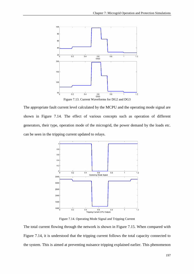
Chapter 7: Microgrid Operation and Protection Simulations
197
Figure 7.13. Current Waveforms for DG2 and DG3
The appropriate fault current level calculated by the MCPU and the operating mode signal are
shown in Figure 7.14. The effect of various concepts such as operation of different
generators, their type, operation mode of the microgrid, the power demand by the loads etc.
can be seen in the tripping current updated to relays.
Figure 7.14. Operating Mode Signal and Tripping Current
The total current flowing through the network is shown in Figure 7.15. When compared with
Figure 7.14, it is understood that the tripping current follows the total capacity connected to
the system. This is aimed at preventing nuisance tripping explained earlier. This phenomenon

Chapter 7: Microgrid Operation and Protection Simulations
198
becomes more dominant in an islanded microgrid with many DGs. The protection scheme
proposed also tackles this issue by following the total capacity connected to the network.
Figure 7.15. Total Current flow in the Network
7.4. Communication Interface Simulations
Following the universality approach assumed in this research, the components of the
proposed microgrid system have been modeled in MATLAB/Simulink using the Logical
Nodes (LNs) defined in the international communication standard IEC 61850 and its recent
extension for DERs IEC 61850-7-420. Initially, relays and distributed generators have been
modeled by equipping them with communication modules which are essential for the
realization of the proposed scheme. Figure 7.16 shows the new model designed for relays.
In the relay model, there are two key parameters for the proper operation of relays: operating
fault current IRelay and the time delay for selectivity trelay. The former is calculated in a unique
fashion as proposed by the authors in the Chapter 5. On the other hand, time delay can be
determined in two different ways. Firstly, depending on the microgrid structure suitable time
delays for selectivity can be calculated and embedded in the Communication and Control
module (CCM). Alternatively, the selectivity can also be calculated by the MCPU on the fly

Chapter 7: Microgrid Operation and Protection Simulations
199
and fed to the relays as proposed in [182]. This feature will make the system very versatile
and new connections can be performed easily. The anticipated drawback is the design and
implementation of an appropriate algorithm which can analyze the current status of the
network and assign incremental time delays to the relays.
Figure 7.16. Relay Block with XCBR, PTOC and TCTR LNs
Once these parameters are calculated by the MCPU, they are sent to each individual relay and
stored in PTOC which detects AC over-current flow in a predetermined direction. Therefore,
the detection threshold IRelay is stored in PTOC. The time delay trelay, which represents the
delay applied on detection signal sent to CSWI, is also stored inside PTOC. CSWI is used to
send a trigger signal to the XCBR, circuit breaker, in case an over-current signal is received
from PTOC. It is worthy to note here that in modeling the relay, instead of logical node
PIOC, which detected instantaneous over-current or rate-of-rise, PTOC which has the
capability to detect fault currents according to their directions, is utilized. This modification
is required since fault currents may flow in both directions in microgrids. Furthermore, the
relay model is equipped with a remote CCM to update operating fault currents and time
delays calculated by the MCPU. This relay model is used for all relays regardless of their
positions as load connecting, DG connecting or inter-bus relays.

Chapter 7: Microgrid Operation and Protection Simulations
200
For a proper communication to be achieved in the network DGs need to be modeled in
accordance with IEC 61850-7-420 and equipped with a communication module which will
report the parameters such as status, rated current and DG type to the MCPU. Due to their
distinct features each DG type is modeled individually. Figure 7.17 shows the generic model
used to represent DGs in MATLAB environment.
Figure 7.17. DG model with DRCT and DRCS LNs
The remote communication and control is connected to DRCS and DRCT which represent
DER controller status and DER controller characteristics, respectively. In the proposed
system, MCPU requires three parameters from every DG. These are DG status, DG type (i.e.
inverter-interface or rotating machine) and the rated current value. The first parameter can be
extracted from DRCS. The data DRCS.ModOnConn indicates whether the DG is `On and
Connected`. When the DG is in operation, i.e. it is ON, and connected, then
DRCS.ModOnConn is set `True`. The data DRCS.ModOffAval and DRCS.ModOffUnav
indicate whether the DG is `OFF but available to start` or `OFF and not available to start`. In
either case the DG will be OFF and will not contribute any fault current. Therefore, if
DRCS.ModOffAval or DRCS.ModOffUnav is set `True` it means the D is not in operation.
Following relay calculation scheme, statusDG can be extracted from values of

Chapter 7: Microgrid Operation and Protection Simulations
201
DRCS.ModOnConn, DRCS.ModOffAval and DRCS.ModOffUnav. This can be
represented with the logical expression given in (7.1):
(7.1)
Equation (7.1) is implemented in Simulink as in Figure 7.18:
Figure 7.18. StatusDG module (in MCPU) to extract connection status of DGs
The DG type is required for fault current estimation and it is listed in DRCT.DERtyp. This
parameter can be set to 2 to represent rotating machines. This will imply that a factor of 5
shall be used in estimating fault current of the DG. Alternatively, DRCT.DERtyp can be set
to 3 or 4 to represent fuel cell or PV panel. This will imply that a factor of 1.5 shall be used in
estimating fault current of the DG since these are inverter-interface DGs (IIDGs).
The rated operating current of the DG can be extracted from DRCT. DRCT.MaxWLim
represents the maximum power rating of the generator. From rated current, the fault currents
of a rotating machine and an inverter-interfaced DG can be extracted as in (7.2) and (7.3):
IfaultDG = (DRCT.MaxWLim/Voltage) * 5 (7.2)
IfaultDG = (DRCT.MaxWLim/Voltage) * 1.5 (7.3)
Equations (7.2) and (7.3) are implemented in Simulink as shown in Figure 7.19. For rotating
machines, DRAT block might be useful in supplying the fault current of the DG. The two
parameters DRAT.FltARtg and DRAT.MaxFltRtg represent the maximum fault and short
circuit currents supplied by the generator and they can be directly used by MCPU. The only
drawback is that these parameters are listed as `Optional` in the Logical Node, DRAT, and

Chapter 7: Microgrid Operation and Protection Simulations
202
they may be omitted for some models. The other parameters used above, on the other hand,
are all listed as `Mandatory` in their respective LN.
Figure 7.19. IfaultDG module (in MCPU) to extract fault contribution of DGs
Likewise, ZINV block might be useful in supplying the fault current of IIDGs. The parameter
ZINV.Wrtg represents the maximum power rating of the inverter. This value can be used
instead of DRCT.MaxWLim in (7.3). This replacement does not improve the accuracy, since
the same calculation is carried out, and this parameter is listed as `Optional` in the Logical
Node, ZINV.
7.4.1. Simulation Works and Resultant Data Maps
In order to substantiate the operation of the modeled blocks and the operation of the proposed
protection scheme, the system shown in Figure 7.20 is described over a predetermined
scenario.
Figure 7.20. The system for which communication modeling is performed

Chapter 7: Microgrid Operation and Protection Simulations
203
The system includes two inverter-interfaced DGs (DG1 and DG2) and a diesel generator
(DG3) which is used to set the frequency and voltage under islanded conditions. The DGs are
operated under conventional droop control and share the loads in accordance with their
capacities.
A specially designated scenario is applied to show different aspects of the protection scheme:
1. The system starts operation with full load, all DGs are on and the MG operates in Grid-
Connected Mode.
2. At t=0.2 sec a fault occurs in Load 1 (L1) and Circuit Breaker (CB) 2 opens. Due to less
power demand in the system DG1 also turned off.
3. At t=0.5 sec the utility grid experiences power outage for maintenance reasons and MG
becomes islanded.
4. At t=0.65 sec, while MG is operating in islanded mode another fault occurs in L4 and
CB8 opens.
5. At t=0.75 sec, the connection with the utility grid is restored and MG operates in grid-
connected mode.
6. At t=1 sec, the fault in L1 is cleared and it is reconnected to the system. Due to
increased power demand in the network DG1 is also put into operation.
The system shown may assume different structures depending on the status of CB4 and CB5.
In the beginning CB4 is open and CB5 is connected. Therefore, the microgrid has two
branches in its structure. After t=1.25 sec, CB4 closes and CB3 opens. The microgrid
assumes a one-line structure. The changing selective levels of the relays are shown in the
tables given below. Comparing different selective level of a particular relay for different
microgrid structures shows the need for selectivity coordination. The automated operation
steps mentioned in Chapter 4 fill this gap.

Chapter 7: Microgrid Operation and Protection Simulations
204
As mentioned earlier, it is assumed that microgrid is sufficiently small and `k` is set to 1. This
means that DGs supply their maximum fault current for any fault. The parameters of the
network components used by the communication system are listed in Table 7.11. At t=0.5 sec
the network component parameter table is as shown in Table 7.12.
TABLE 7.11 – NETWORK COMPONENT PARAMETERS AT T=0 SEC
StatusDG DG type Ifault
DG1 DRCS.ModOnConn= True DRCT.DERtyp = 4 (DRCT.MaxWLim/Voltage) * 1.5
DG2 DRCS.ModOnConn= True DRCT.DERtyp = 3 (DRCT.MaxWLim/Voltage) * 1.5
DG3 DRCS.ModOnConn= True DRCT.DERtyp = 2 (DRCT.MaxWLim/Voltage) * 5
CB1 CB
2
CB 3 CB 4 CB 5 CB
6
CB 7 CB 8
XCBR.Pos ON ON ON OFF ON ON ON ON
Selective Level 1 2 2 NA 3 3 4 4
The relay fault current value = Grid contribution + DG1 + DG2 + DG3
= IfaultGrid + (DG1.DRCT.MaxWLim/Voltage) * 1.5 + (DG2.DRCT.MaxWLim/Voltage)*1.5
+(DG3.DRCT.MaxWLim/Voltage)*5
TABLE 7.12 – NETWORK COMPONENT PARAMETERS AT T=0.5 SEC
StatusDG DG type Ifault
DG1 DRCS.ModOffUnav = True DRCT.DERtyp = 4 (DRCT.MaxWLim/Voltage) * 1.5
DG2 DRCS.ModOnConn = True DRCT.DERtyp = 3 (DRCT.MaxWLim/Voltage) * 1.5
DG3 DRCS.ModOnConn = True DRCT.DERtyp = 2 (DRCT.MaxWLim/Voltage) * 5
CB1 CB 2 CB 3 CB 4 CB 5 CB 6 CB 7 CB 8
XCBR.Pos OFF OFF ON OFF ON ON ON ON
Selective Level N/A N/A 1 N/A 2 2 3 3
The relay fault current value = DG2 + DG3 =
(DG2.DRCT.MaxWLim/Voltage)*1.5 + (DG3.DRCT.MaxWLim/Voltage)*5
Figure 7.21 shows the internal details of MCPU while the connections of MCPU with the DG
and Relay models are given in Figure 7.22.

Chapter 7: Microgrid Operation and Protection Simulations
205
Figure 7.21. MCPU operating with modeled Relay and DG blocks
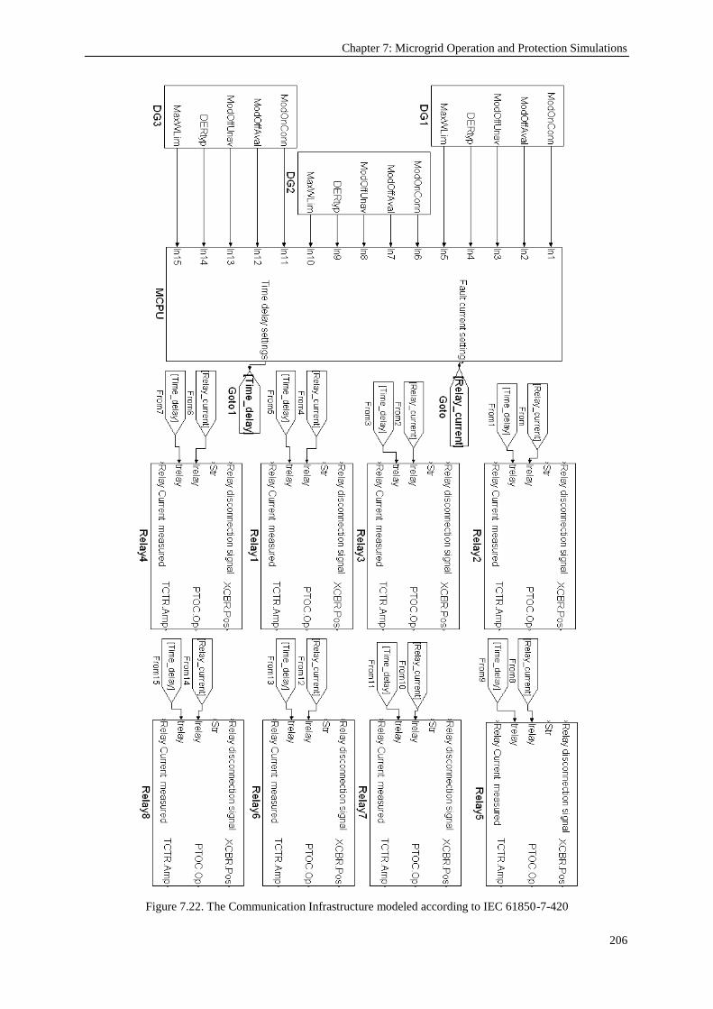
Chapter 7: Microgrid Operation and Protection Simulations
206
Figure 7.22. The Communication Infrastructure modeled according to IEC 61850-7-420

Chapter 7: Microgrid Operation and Protection Simulations
207
7.5. Conclusion
This chapter has investigated the impacts of microgrids as well as their different structures
and operating conditions on the power networks. New grid components such as DGs and EVs
have been utilized and the microgrid has been operated as (i) a stand-alone system, (ii) a
system connected to transmission network, (iii) a system connected to distribution network.
Simulation results are utilized as preliminary assumptions during the design of the novel
microgrid protection system.
Secondly, the developed protection system with MCPU has been implemented in
MATLAB/Simulink environment. The proposed system has been modeled in the
MATLAB/Simulink environment and simulation works were carried out with a
predetermined scenario which highlights different aspects of the protection scheme proposed.
The new relay and DG models with communication modules along with the MCPU were
modeled and tested. Obtained waveforms confirm successful operation since the protection
system can adapt itself to the changes occurring in the microgrid.
For universal operation purposes, special attention must be paid to the communication
protocol utilized for the communication of data within the system and a standard packet-type
for the relay and distributed generator communication can be developed. If each grid
component is equipped with a simple communication device to report its status, rated current
and fault contribution, then a universal concept of connection can be achieved. This may
prove useful for the implementation of plug and play concept in microgrids.
To this end, the communication infrastructure based on IEC 61850 and its recent extension
IEC 61850-7-420 has been implemented in MATLAB/Simulink Environment. The new relay

Chapter 7: Microgrid Operation and Protection Simulations
208
and DG models with communication modules were modeled and implemented in
MATLAB/Simulink. The utilized models are very versatile and can be used in modeling
different microgrids. The universal modeling of DGs regardless of their models and
manufacturers is very important for having a universal concept of DG connection. Sample
Data Maps are illustrated on a predetermined scenario which highlights different aspects of
the protection scheme proposed. Obtained results verify the reliability and viability of the
developed protection system.

Chapter 8: Operation of the Proposed Protection System under Different Protection Scenarios
209
Chapter 8
Operation of the Proposed Protection System under Different
Protection Scenarios
Publications pertaining to this chapter:
1) Taha Selim Ustun, Cagil Ozansoy, Aladin Zayegh, "Differential Protection of Microgrids with Central
Protection Unit Support”, IEEE PES Conference on Innovative Smart Grid Technologies, Sao Paulo,
Brazil, ISGT-LA 2013, 15 – 17 April, 2013 (under review).
8.1. Introduction
Preceding chapters have explained the details of the microgrid protection system developed
in this research. This chapter is the final step of this research where the interaction of the
developed protection system with other protection systems is investigated. This interaction
might occur in two ways. Firstly, due to the rapid extension of microgrids, more than one
protection system might be implemented in a certain power network. Until all necessary
adjustments have been made, several protection schemes might co-exist in the microgrid.
This is particularly true, when it is considered that overall augmentation of an existing
network at one instance is very rigorous and expensive. Gradual and continuous migration to
a certain protection system can be the only practical solution for this problem. Consequently,
for a certain period, it would be required that several protection systems operate
simultaneously on the network.

Chapter 8: Operation of the Proposed Protection System under Different Protection Scenarios
210
Secondly, these protection systems can be used to support each other in case of need.
Different protection systems have different advantages and short-comings. In future
implementations, a smart microgrid central protection unit shall be able to investigate the
network conditions and decide the most appropriate protection system. Furthermore, in case
of a fault in the existing protection system, e.g. a communication link error in differential
protection, another protection system can be used as a roll-back system for back-up
protection.
As it has been expressed in various Chapters of this thesis, different protection schemes have
been proposed for microgrids [84, 94, 146] and there is continuous research effort in this
direction. As a strong candidate for future microgrid protection systems, differential
protection is also examined [214]. Differential protection method has some inherent
advantages such as immunity to voltage variations, ability to operate without prior knowledge
of the fault levels and convenient acceptance of new deployments/connections [215]. This
versatile nature of differential protection complies with the demanding nature of the
microgrids. Consequently, this particular method is considered to be very promising for the
future of microgrid protection systems.
However, there are some aspects which require to be reinforced before differential protection
can be widely implemented. These include implementation of differential protection on
multi-terminal elements and long power lines as well as a back-up scheme which can be used
in the case of a communication failure and/or synchronization. Therefore, in this chapter, the
two types of interaction schemes mentioned above, namely co-existence of different
protection schemes in a microgrid and use of a protection system as a back-up, have been

Chapter 8: Operation of the Proposed Protection System under Different Protection Scenarios
211
investigated for the developed protection system and the differential protection system. This
is by no means restrictive and can be extended for other protection systems as well.
8.2. Operation with Other Microgrid Protection Systems
It is essential for future microgrid protection systems to be able to operate together on a given
network. Although co-existence of several protection systems is not desirable from technical
and financial point of view, some practical considerations might necessitate it. Electrical
networks are operating entities and it is not possible to interrupt the power delivery for a full-
fledge network upgrade. Not only that, but also such an undertaking will be toilsome and
expensive. Therefore, it is expected that a gradual migration will be assumed in power
networks where the new deployments shall be integrated into the desired protection system.
As it is explained in Chapter 2 and 3, the unprecedented nature of microgrids requires novel
protection techniques. Consequently, already existing protection system in older parts of the
power network will be replaced over time. The proposed protection system has the capability
to operate on dynamic microgrid structures, handle new connections/deployments, extract
equipment hierarchy for changing structures and assign protection parameters on the fly. For
this reason, it is appreciable that the proposed system will be selected as the novel microgrid
protection implemented in the microgrids. Wherefore, it has to be able to co-operate and co-
exist with other protection system during this migration period. The protection system
developed in this research also has the ability to interact with other protection systems and
coexist in one power network. This can be achieved by implementing Data Maps and MCPU
accordingly.
Consider the system shown in Figure 8.1 where a power network has two different protection
systems implemented. “Other Protection” refers to an earlier protection scheme which has

Chapter 8: Operation of the Proposed Protection System under Different Protection Scenarios
212
already been implemented in the microgrid while “The Proposed Protection System” refers to
the protection system developed in this research.
Figure 8.1. Interaction of the Proposed Protection System with Others
As shown, the previous network consists of CB1, CB2, CB3 and downstream connections of
CB3, i.e. DG1, DG2 and Load1. This portion of the network has been under operation and
implemented a different type of protection. The new deployments which are connected under
CB4 are relatively new and for this reason, they implement a more desirable protection
system which is tailor-made for microgrid operation. It is not feasible nor is it cost-effective
to propose that the already-existing network be replaced at one instance. Therefore, status
quo necessitates co-operation and co-existence of these protection systems.
This can be achieved by adjusting the Data Map of the Proposed Protection System as shown
in Table 8.1. When the table is examined, it is observed that relays of “Other Protection
System” are not listed. This is due to the fact that, these relays are not handled by MCPU of
“The Proposed Protection System”. Therefore, they are not accounted for. It is also worthy to

Chapter 8: Operation of the Proposed Protection System under Different Protection Scenarios
213
note that the fault current contribution of the grid is not taken into account by the proposed
protection system since the coupling transformer is included in the protection zone of the
other protection system. Consequently, it is assumed that the “Other Protection System”
ensures safe operation by manipulating CB1 and CB2, accordingly. As for the effect of
IfaultGRID on other relays, this can be extracted from short circuit analysis report and provided
to MCPU.
TABLE 8.1. DATA MAPS FOR OPERATION WITH OTHER PROTECTION SYSTEMS
Relays Operating Fault Current Fault Detection
(1 – Y, 0 – N)
Time delay for Selectivity
R4 IR4 0 t4
R6 IR6 0 t6
R7 IR7 0 t7
…
DGs Irated IfaultDGx Status (1-ON, 0-OFF)
DG3 IDG3 IfaultDG3 1
DG4 IDG4 IfaultDG4 1
DG5 IDG5 IfaultDG5 0
TABLE 8.2. SELECTIVITY TABLE FOR OPERATION WITH OTHER PROTECTION SYSTEMS
Relay ID Operating Current Downstream Relay ID Downstream Relay Operating Current
R4 IrelayR4 R6 IrelayR6
R4 IrelayR4 R7 IrelayR7
R6 IrelayR6 IRDG3 IrelayIRDG3
R6 IrelayR6 IRLoad2 IrelayIRLoad2
R7 IrelayR7 IRLoad3 IrelayIRLoad3
R7 IrelayR7 IRDG4 IrelayIRDG4
R7 IrelayR7 IRDG5 IrelayIRDG5
The selectivity can be assured in two ways. If there is a communication link established with
CBs operating under “Other Protection System” then the selective operation explained in
Chapter 5 can be implemented. If that is not the case, then the Proposed Protection System
will implement selectivity in its own domain as shown in Table 8.2. Here, R4 is coupled with

Chapter 8: Operation of the Proposed Protection System under Different Protection Scenarios
214
R6 and R7 for selective operation while R6 and R7 are coupled with their downstream relays
for 2-pair selective operation as explained in Chapter 5.
When the network operator decides to upgrade some sections of the network and integrate
them into the proposed system, this can easily be performed. An example case is given in
Figure 8.2 where CB1 and CB2 are integrated into the proposed system. The branch
downstream of CB3 is still operating on the previous conditions. Should there be additional
investment by the network operator, this branch can also be integrated. In this manner, the
gradual emigration to the proposed protection system can be finalized.
Figure 8.2. Status of the network after inclusion of CB1 and CB2 in the Proposed Protection System
Table 8.3 shows the updated Data Maps in MCPU for the new case. Since grid-connecting
relays are included in the system, the fault current contribution of the utility grid is taken into
account by the proposed protection system. The branch located downstream of CB3 is
protected by “Other Protection System”; therefore it is assumed that necessary precautions
are taken to protect DG1, DG2 and Load1.

Chapter 8: Operation of the Proposed Protection System under Different Protection Scenarios
215
TABLE 8.3. DATA MAPS AFTER INTEGRATION OF CB1 AND CB2
Grid-Connected Islanded
Operating Mode 1 0
Grid Fault
Contribution IfaultGRID
Relays Operating Fault Current Fault Detection
(1 – Y, 0 – N)
Time delay for Selectivity
R1 IR1 0 t1
R2 IR2 0 t2
R4 IR3 0 t4
R6 IR3 0 t6
R7 IR3 0 t7
DGs Irated IfaultDGx Status (1-ON, 0-OFF)
DG3 IDG3 IfaultDG3 0
DG4 IDG4 IfaultDG4 1
DG5 IDG5 IfaultDG5 1
The selectivity pairs for the new case can be arranged as shown in Table 8.4. 1st branch
incorporates all the equipment controlled by the proposed protection system. The interaction
between two protection schemes occurs in the 2nd
branch. R2 is paired with R3 as a back-up
protection in case R3 cannot interrupt the fault current. The synchronization between these
relays can be achieved through communication lines, if any, or by any other proper means.
TABLE 8.4. 2-PAIR SELECTIVITY LIST AFTER NEW INTEGRATIONS
Relay Hierarchy 1st branch Selectivity pairs
5 R1
4 R2
3 R4
4 R6
1 R7
2nd
branch
2 R2
1 R3

Chapter 8: Operation of the Proposed Protection System under Different Protection Scenarios
216
The process mentioned above is vital for implementing gradual migration towards a desired
microgrid protection system. This is all the more crucial, if the mentioned protection system
requires special equipment and deployments. Furthermore, the flexibility of the proposed
protection system, which is illustrated above, can be utilized for accepting new deployments
in the microgrid. New deployments can be easily detected and integrated into the established
system. Some sections in Chapter 4 have been dedicated to plug-and-play concept which
serves for new deployments. This can be achieved while the proposed system is co-operating
on an electrical network along with other protection systems.
The ability to implement the proposed protection system simultaneously with other schemes
is also a very important and necessary feature. Having the flexibility given above, the
proposed protection system is a good candidate for future microgrid protection systems.
8.3. Usage of Proposed System as a support for Differential Protection
One of the most widely used methods for power system protection is differential protection
[216]. It is based on the fact that under all circumstances the sum of all the currents in the
protected zone shall add up to zero except for internal faults. Since it only uses electrical
current value from the power system, it does not require voltage measurements and, hence, is
less sensitive to power swings, sudden load changes and voltage variations [217]. Differential
protection is especially attractive if the both ends of the apparatus are close to each other
[218]. Consequently, it is commonly used to protect transformers, generators, bus bars and
motors. In addition, the use of differential protection on short transmission lines dates back to
as early as 1930s [219].
Consider the system given in Figure 8.3 where a power system component, such as a
transformer, motor, load or power line, is protected with differential protection. As shown,

Chapter 8: Operation of the Proposed Protection System under Different Protection Scenarios
217
this protection scheme is an application of Kirchhoff‟s Current Law. Under normal
circumstances the currents flowing on the secondary sides of Current Transformers (CTs) add
up to zero and the coil would not have any energy to operate [220]. Should there be fault, this
equilibrium will not hold anymore and the relay will be triggered.
Figure 8.3. A sample differential protection topology
The application of differential protection to power lines require communication links since
the two terminals of the protected component are located far away from each other [221]. As
illustrated in Figure 8.4, two relays located at the either end of the power line receive local
measurements and report these values to the other relay. However, in this case, the
communication delay shall be taken into account and the measurements received from the
communication link shall be compared with the corresponding local measurements. This
requires a synchronization algorithm based on time-stamping concept where the timing of
each measurement is recorded as well as the measurement value. The application extent of
differential protection to power lines was highly limited with analog communication lines due
to signal attenuation. Therefore, this protection scheme has been used mostly on short lines
which cannot be effectively protected by distance protection. However, the latest
developments in digital communication and microprocessor-based relays made this
application possible on long lines [215].

Chapter 8: Operation of the Proposed Protection System under Different Protection Scenarios
218
Figure 8.4. Differential Protection for power lines
Along with its advantages, differential protection has its own important drawbacks. Among
these are; dependence on high communication performance when used for the protection of
long feeders, the need for uninterrupted communication link, current transformer mismatch or
saturation, synchronization and application to multi-terminal systems.
Figure 8.5. A double-slope restraint characteristic [222]
The mismatch between CTs and their saturation are major concerns since they cause relays to
measure false differential currents. In order to compensate these measurements errors, a
threshold is used to restrain the operation of the relays. Following this definition threshold
current is called restraint current [222]. It is calculated from local parameters and increases
with increasing current to match higher measurement errors at higher levels. A typical
restrain characteristic is shown in Figure 8.5. The operation of the relay is controlled with an
adjustable threshold, Imin. The restraint current increases with increasing differential current.
Two different coefficients are used to control rate-of-increase where the smaller slope K1 is
Chapter 8: Operation of the Proposed Protection System under Different Protection Scenarios
219
used to compensate CT mismatch while larger slope K2 is used to compensate CT saturation
at very high current values.
The currents are calculated as follows;
Iop= Idifferential = iA + iB (8.1)
Irestraint = ƒ ( iA , iB ) (8.2)
If Idifferential > g(Irestraint) => Operate! (8.3)
where iA denotes the average or the magnitude of the current, ƒ() and g() denote
independently adjustable functions. The former is utilized to calculate the restraint current
based on measurements whereas the latter defines the operation condition based on
differential and restraint currents.
Various calculation methods, i.e. definitions of ƒ(), are reported in the literature for restraint
current determination. Different methods, in (8.4), (8.5), prove to have better performance
under different fault conditions [218].
Irestraint = iA - iB (8.4)
Irestraint = iA + iB (8.5)
Irestraint = max (iA , iB) (8.6)
Consequently, the structure of the network and the possible fault conditions might be
considered while selecting the proper restraint method. Moreover, adjusting the restraint
current calculation method according to changes in microgrids or recently developed
concepts may provide the most efficient and effective differential protection. This point is
further studied in the next section where the proposed system is explained in detail.
Another challenge is the adjustment of differential protection for multi-terminal components
where several inputs shall be arranged to define a protected zone, see Figure 8.6. Especially,

Chapter 8: Operation of the Proposed Protection System under Different Protection Scenarios
220
if there are changing connections, differential protection has to be implemented with a digital
setup. Otherwise, the CTs have to be manually coupled and decoupled.
Figure 8.6. Multi-terminal protection zone with several currents
For this purpose, micro-processor based relays are used where all connections are reported to
the microprocessor. Then, they are grouped according to the state of connections. That being
said, it is extremely difficult to implement this concept on power lines where there are
numerous components continuously connect to and disconnect from the protection zone.
Therefore, as shown in the next section, a comprehensive control system might be used to
support the differential protection.
The most important disadvantage is the dependence on the communication link between the
relays. The measurements are reported in a continuous fashion and a possible failure in
communication lines proves to be lethal for differential protection. The malfunctioning of the
relays or the complete collapse of the protection is out of question. Some back-up strategies
are mentioned in the literature, to be used in case of communication failure. But they are not
developed as a complete system [215]. The next section explains an alternative back-up
strategy which can be used in case of communication failure.

Chapter 8: Operation of the Proposed Protection System under Different Protection Scenarios
221
8.3.1. Differential Protection with Microgrid Central Protection Unit (MCPU)
As outlined in the previous section, the wide-scale application of differential protection to
modern microgrids requires some adjustments. In this section, an MCPU is used to support
these shortcomings and reinforce differential protection as the promising protection scheme
of future networks. This system is designed to tackle the following issues:
Adjustment of restraint current calculation algorithm in accordance with changing
network conditions and/or Incorporating new calculations algorithms developed as a
result of research in this field
Integration of multi-terminal protection zones into differential protection
Proposing an alternative system which can be used in a back-up strategy if there is a
failure in communication links
For this purpose, the protection system developed in this research [55], shown in Figure 8.7,
is utilized. This system has an MCPU to communicate with all relays and DGs in the
microgrid. In this fashion the network can be effectively monitored and necessary
adjustments can be made. The strength of this topology is its ability to be tailored for
different applications such as fault current limiters [146] or differential protection.
MCPU communicates with every network component and each new
connection/disconnection is reported to it. Therefore, MCPU has the ability to extract the
current state of the network, list the connected entities and choose a proper restraint current
calculation method. In order to achieve this, a comprehensive algorithm should be
implemented in the MCPU. Similarly, if it is desired to upload a completely novel algorithm,
then MCPU will be able to achieve this in a centralized manner. This will decrease the burden
on network operators who, otherwise, would need to visit each relay individually.

Chapter 8: Operation of the Proposed Protection System under Different Protection Scenarios
222
Figure 8.7. Topology of the Developed Differential Protection with MCPU
Secondly, MCPU assists multi-terminal differential protection. Multi-terminal protection can
be locally implemented if all the terminals are connected to the same point, e.g. buses with
more than two terminals. However, if it is required to cover a protection zone with
differential protection then additional support is necessary. For example, when a power line is
protected, the connections of compensators, shunt reactors etc. shall be taken into account.
The initial charging currents of these components shall be added to the differential protection
scheme.

Chapter 8: Operation of the Proposed Protection System under Different Protection Scenarios
223
Table 8.5 shows a sample multi-terminal differential protection zone implemented in Figure
8.7. Since Load 2 and DG4 are not connected to the network, their currents are not included
in the protection scheme. The coupling transformer is also protected with differential
protection (Zone 3) and its charging current is considered when the network is re-connects to
the grid after being islanded. The changes in the microgrid are immediately reflected to the
protection zones. Furthermore, new deployments can be easily inducted without the need for
any physical CT or communication link installation between the relays.
TABLE 8.5. MULTI-TERMINAL DIFFERENTIAL PROTECTION ZONES
Protection Zone No. Active Currents Non-active Currents Charging Currents
1 IDG1, IDG2, Iload1 Iload2 -
2 IDG4, Iload3, Iload4 IDG3 -
3 Igrid - Icoupling_transformer
The final and most important contribution of the proposed system is the back-up protection
utilized in case of communication failures. The fault current estimation methodology
developed in this research which is used to program over-current relays [55, 146, 182] has
been presented in earlier chapters. The microgrid is continuously monitored and fault currents
are estimated based on the number and type of the components connected to it. Once the fault
currents are estimated and the operating currents are reported to relays, the relays operate
individually without any communication process.
In other words, communication is only required when there is a change in the microgrid and
fault currents need to be estimated. Since it uses local decision-making, shown in Figure 8.8,
this scheme is less dependent on the communication. It is proposed to use this scheme as the
back-up of differential protection. Should there be a communication and/or synchronization
problem, the system can roll-back to the over-current protection presented in previous
chapters. This can be easily implemented in some differential protection schemes where over
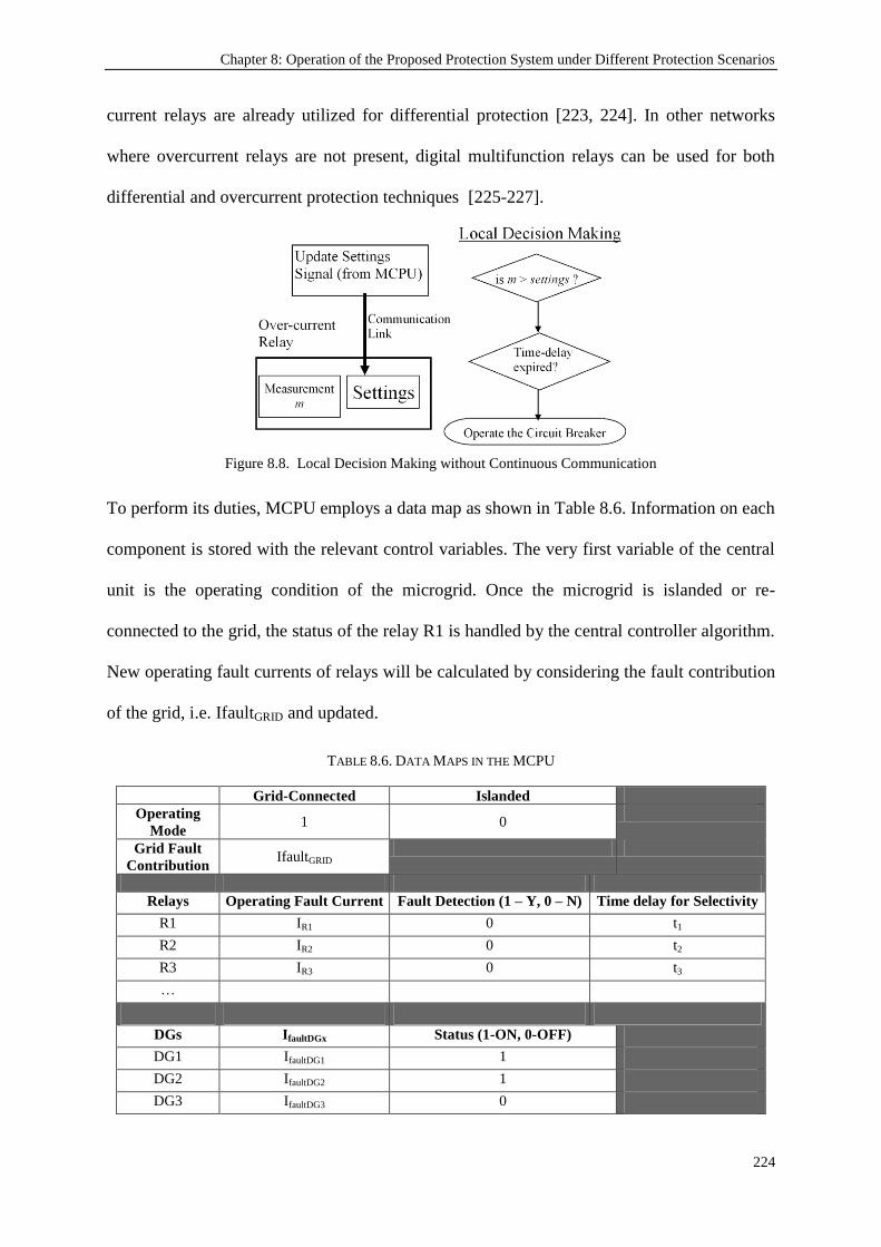
Chapter 8: Operation of the Proposed Protection System under Different Protection Scenarios
224
current relays are already utilized for differential protection [223, 224]. In other networks
where overcurrent relays are not present, digital multifunction relays can be used for both
differential and overcurrent protection techniques [225-227].
Figure 8.8. Local Decision Making without Continuous Communication
To perform its duties, MCPU employs a data map as shown in Table 8.6. Information on each
component is stored with the relevant control variables. The very first variable of the central
unit is the operating condition of the microgrid. Once the microgrid is islanded or re-
connected to the grid, the status of the relay R1 is handled by the central controller algorithm.
New operating fault currents of relays will be calculated by considering the fault contribution
of the grid, i.e. IfaultGRID and updated.
TABLE 8.6. DATA MAPS IN THE MCPU
Grid-Connected Islanded
Operating
Mode 1 0
Grid Fault
Contribution IfaultGRID
Relays Operating Fault Current Fault Detection (1 – Y, 0 – N) Time delay for Selectivity
R1 IR1 0 t1
R2 IR2 0 t2
R3 IR3 0 t3
…
DGs IfaultDGx Status (1-ON, 0-OFF)
DG1 IfaultDG1 1
DG2 IfaultDG2 1
DG3 IfaultDG3 0

Chapter 8: Operation of the Proposed Protection System under Different Protection Scenarios
225
The MCPU continuously monitors the statuses of all DGs in a synchronized manner by
communicating with them using a Publish/Subscribe peer-to-peer messaging (similar to IEC
61850‟s GOOSE) messaging system. If a DG disconnects at any time for example, the fault
currents are re-calculated by considering the fault current contribution (IfaultDGx) of that
particular DG. In this way, the system is ready for any fault condition before any fault,
actually, occurs.
The prospective relay settings are recalculated and updated based on the DG status data. In
Table 8.2, the status of DG3 (alternatively status of R7, not shown) shows that it is not in
operation. This may be due to maintenance, the intermittent nature of RE resources (no sun or
wind) or the excess local generation. In case the local consumption increases and DG3 is put
back into operation, this is reported back to the MCPU either through DG3‟s or R7‟s status
signals. The new fault current contribution IfaultDG3 is taken into account and new fault
levels are updated for all the relays in the grid. Similarly, if DG2 is shut down for a certain
reason, then it is reported to the MCPU through DG2‟s or R5‟s status signal. The data map
will be updated and new fault current level calculations will be performed without IfaultDG2.
For a particular relay, the operating fault current (the current level that causes the relay to
trip) is calculated as in (8.7). The details of this calculation process have been given in
Chapter 3 and Chapter 5.
(8.7)
The MCPU uses a simple algorithm shown in Figure 8.9. The status of R1 has been given a
special consideration since it imposes the operating mode and grid fault contribution. The
details of the algorithm implemented have been as presented in Chapter 3, Conceptual
Design.
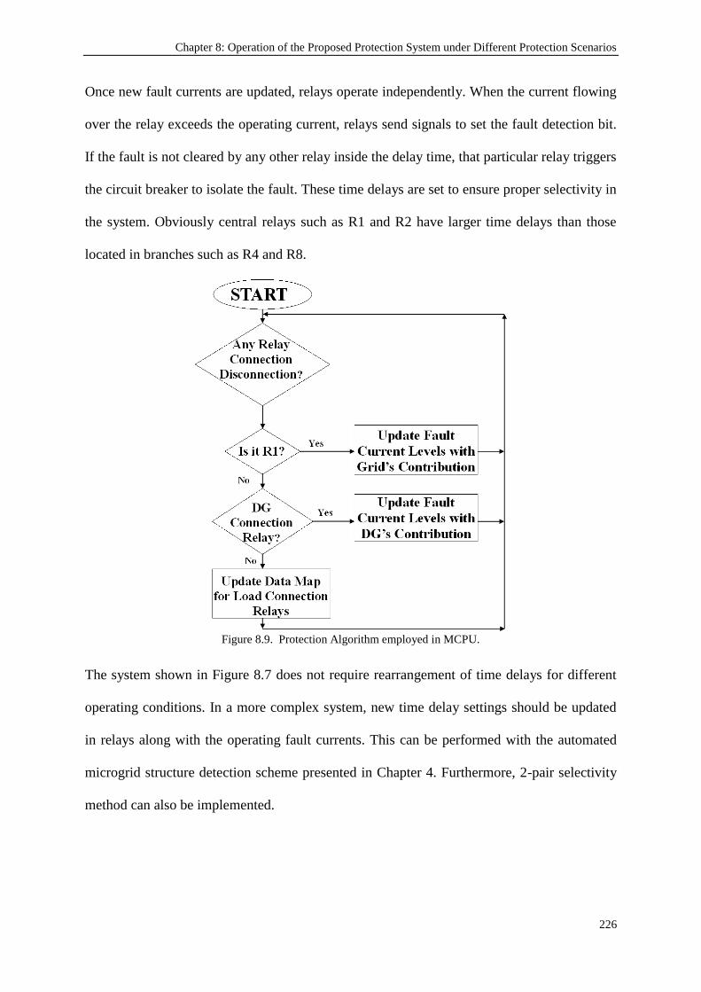
Chapter 8: Operation of the Proposed Protection System under Different Protection Scenarios
226
Once new fault currents are updated, relays operate independently. When the current flowing
over the relay exceeds the operating current, relays send signals to set the fault detection bit.
If the fault is not cleared by any other relay inside the delay time, that particular relay triggers
the circuit breaker to isolate the fault. These time delays are set to ensure proper selectivity in
the system. Obviously central relays such as R1 and R2 have larger time delays than those
located in branches such as R4 and R8.
Figure 8.9. Protection Algorithm employed in MCPU.
The system shown in Figure 8.7 does not require rearrangement of time delays for different
operating conditions. In a more complex system, new time delay settings should be updated
in relays along with the operating fault currents. This can be performed with the automated
microgrid structure detection scheme presented in Chapter 4. Furthermore, 2-pair selectivity
method can also be implemented.

Chapter 8: Operation of the Proposed Protection System under Different Protection Scenarios
227
8.3.2. Communication Infrastructure Reliability Considerations
In addition to the above-mentioned advantages, proposed protection system is more reliable
than differential protection from communication perspective. This is due to the fact that the
communication used in differential protection is required to be continuous while the proposed
system needs communication to update protection parameters. In recent years, different
reliability assessment methods have been proposed such as Reliability Block Diagram (RBD)
[185], 3RF Technique [186], and Software Reliability Allocation [187]. The failures are
classified and new parameters are introduced to design a more comprehensive reliability
assessment scheme [184, 188].
These systems consider issues related to relay hardware, relay software, ancillary equipment,
communication units and human errors. [186, 188]. All of them consider the probability of a
failure occurrence and its impact on system dependability and security as defined by IEEE
standard C37.100-1992 [189]. The probability of a failure is defined by [187, 190]:
(8.8)
where all the individual probability components are added to find the overall value. Equation
(8.8) applies to differential protection schemes, since they require all components to function
perfectly for reliable operation. A failure in any component such as current transformer or a
communication line failure will trigger the collapse of the whole system. The probability of a
failure in differential protection is as follows:
(8.9)
Contrary to this, the proposed system implements a “last-setting-valid” approach in case of a
communication failure. Therefore the probability of a failure in the proposed protection
system can be expressed as in (8.10).

Chapter 8: Operation of the Proposed Protection System under Different Protection Scenarios
228
(8.10)
where n is the total number of independent events.
As shown in Figure 8.8, the operation is independent of the communication link and this
ensures that relays are always set to operate, though it may not be the most desirable
operation point. However, this requires two events:
1) a failure in the communication line,
2) an electrical fault in the network before the communication line is restored.
Therefore the probability of a relay operating following “last-setting-valid” method is the
multiplication of the probabilities of communication link failure and electrical fault:
P[commfault]=P[comm] x P[fault] (8.11)
where P[comm] is the probability of a communication failure occurring in the microgrid
while P[fault] is the probability of an electrical fault occurring in the same microgrid.
It is clearly mentioned in the literature that with the improving technology the hardware
failures are less frequent [187]. Consequently, the value of probability of communication
failure is very small. The values assumed for these probability values are around on the order
of 10-2
or 10-3
[188, 190]. For short term analysis these values may drop as low as 10-5
[192].
Accordingly, replacing these characteristic figures in (8.11) yields probability of failure for
the proposed protection systems:
P[commfault]=0.01 x 0.001 = 10-5
(8.12)
Replacing same figures in (8.9) yields the probability of failure for differential protection
approach. A simple protection setup given in Figure 8.4 incorporates two relays and a
communication link. Therefore the cumulative probability is:
P[failurediff.prot]=0.01 + 0.01 + 0.001 = 0.021 (8.13)

Chapter 8: Operation of the Proposed Protection System under Different Protection Scenarios
229
As a result, the developed protection system proves to be reliable in accordance with the
requirements of the standards [189]. Considering the value of P[commfault], it is concluded
that the possibility of relays operating when there is a communication failure is very small.
Even if they are forced to operate before the communication is restored, the implementation
of “last-setting-valid” method ensures that no catastrophic condition occurs. If, as an
exceptional case, a fault occurs just after a Relay Setting Update process has started, then the
regular communication speed is around 80 ms [193] and this ensures that relay settings will
be updated. In contrast, differential protection requires all components to work perfectly and
this adds to the probability of failure. Consequently, the probabilities of failure given in
(8.12) and (8.13) are substantially different.
Figure 8.10. Fault Probability Distribution in a Multi-Terminal Protection Zone
As the complexity of the protection zone increases, the reliability advantage of the proposed
system becomes more apparent. When there is a multi-terminal protection zone similar to
Figure 8.6, the number of components increases and the difference in failure possibilities

Chapter 8: Operation of the Proposed Protection System under Different Protection Scenarios
230
grows larger. Figure 8.10 depicts the fault probability distribution for different number of
components in a multi-terminal protection zone.
Naturally, higher number of the components increases the likelihood of a fault. However, as
the graph reveals, the rate of increase is much larger for differential protection. This indicates
that some modifications shall be done before conventional differential protection scheme is
implemented in multi-terminal zones. On the other hand, the proposed system sustains a low
rate-of-increase and it is much reliable in more complex systems.
8.4. Conclusions
This chapter has presented the interaction of the protection scheme developed in this thesis
with other conventional protection systems. Two different interaction types which are vital to
microgrid protection have been investigated. One of them envisages the simultaneous
operation of several protection systems until the complete emigration towards a certain
protection system has been completed in a gradual manner. The latter interaction is required
to reinforce protection systems with others wherever it is required.
In this regard, a new communication-assisted protection scheme for microgrids has been
examined. This hybrid protection scheme employs differential current as the primary
approach and reinforces it with MCPU. In this fashion, some of the major drawbacks of
differential current protection are removed with MCPU support. The ability to monitor the
entire microgrid gives the opportunity to choose different restraint current calculation
algorithms and to adjust the multi-terminal zone protection according to the changes in
topology. The proposed system is very versatile and more reliable than conventional
differential protection approach.

Chapter 8: Operation of the Proposed Protection System under Different Protection Scenarios
231
Furthermore, it has been investigated how the protection system developed in this thesis can
be used as a back-up protection scheme which operates under communication failures. The
combinatory usage of two protection systems is feasible and yields very robust and reliable
protection.
The selection of differential protection is not intended to be limiting. These interactions can
be achieved with other protection systems with the help of MCPU and the flexible use of
Data Maps. With the smart programming of MCPUs, future microgrid protection systems
may have the luxury to select from different protection systems depending on the network
conditions. Therefore, protection systems should be designed to be cooperative rather than
being mutually exclusive. The developed protection system serves this purpose as well.
Chapter 9: Conclusions and Future Work
232
Chapter 9
Conclusions and Future Work
9.1. Introduction
This research presents a novel microgrid protection system which comprises a central unit,
i.e. MCPU, and uses a communication network to achieve protection adaptation and
synchronization. Considering the proliferation of DGs and the unprecedented protection
issues appearing due to their impacts on microgrids, such a protection system is a relevant
and timely contribution to the literature. Advantageously, this protection system has been
developed to be versatile and flexible so as to accommodate several microgrid topologies
with different set of grid components and to accept new deployments, respectively. The
utilization of communication lines might seem as a drawback at first sight, however,
smartgrid concept implies that every grid component shall have a communication capability
in power networks. The develop system shall make use of these lines and will not require
installation of separate lines.
Since it is an emerging field in power networks, microgrid concept received a lot of attention
in research circles. In a short span of time, many applications have been made, several
enhancements have been proposed and power engineering has evolved indelibly. However,
relatively little effort has been made towards microgrid protection systems as the researchers

Chapter 9: Conclusions and Future Work
233
mainly focused on RE based DGs, efficiency enhancement, load sharing, stability etc.
Protection issues and considerations come into play only after necessary work has been done
in other fields and microgrids have started to operate. Only after having several DGs installed
in microgrids can we see their impacts on fault currents and fault levels. Therefore, the
existence of this knowledge gap is not coincidental.
Nevertheless, there are some publications focusing on microgrid protection where some
protection schemes are proposed. These solutions are not as comprehensive as the system
proposed in this thesis from several aspects. Firstly, almost all of these solutions are tailor
made for a specific microgrid with a given set of grid components. Any new deployment or
any new connection which adds a new microgrid structure will render these protection
schemes useless. This is a major drawback for universality and compatibility purposes.
On the other hand, some protection schemes have been kept very broad and very open-ended
with the intention of including all possible microgrids with various sets of grid components.
These broad schemes are not developed further and they remain as a conceptual design
without any solid application framework. Consequently, the major concern about these
schemes is the lack of implementation features. Furthermore, majority of these proposed
protection schemes declare that communication will be an indispensible part thereof.
However, there is not any research work focusing on the communication infrastructure of
future microgrids and the standardization of the communication in microgrids to achieve
universal protection schemes that can accommodate all types of grid components.
The research work presented in this thesis has proposed a novel microgrid protection system
which has been designed to be versatile so that it can be implemented in various microgrid

Chapter 9: Conclusions and Future Work
234
topologies with differing set of grid components. It has been designed to be dynamic, i.e. to
follow dynamic changes occurring in the microgrid such as connection changes or new
deployments, and adapt the protection scheme automatically by extracting the resulting
microgrid topology and assigning new operating conditions. Furthermore, this detailed
conceptual design was modeled according to IEC 61850 communication standard to make it
universal and applicable on all sorts of equipment and compliant with IEC 61850 enabled
relays. In order to achieve a system which is fully modeled under IEC standards, several
extensions to IEC 61850 have been proposed for FCLs and EVs.
The overall protection system has been formed by compiling these individual modules in
MCPU with the help of communication lines. This protection system can be used as a stand-
alone system in a microgrid or it can be utilized as a roll-back strategy for other protection
systems in case of a failure. Due to the design strength, proposed protection system does not
require continuous communication. Communication is only required when a change occurs in
the microgrid and this increases the reliability of this system largely.
9.2. Key Contributions of the Research
As mentioned in the section above, the microgrid protection system developed in this
research focused on several aspects of microgrids to devise a more comprehensive system.
Therefore, key contributions of the research spans over different areas which are itemized
below.
A thorough review of the microgrid evolution and the effects of new grid equipments
This research provides information on the newly emerging areas such as microgrids and new
grid equipments such as FCLs and EVs. Various test cases have been explained from around
the globe to reflect the differences in the understanding and interpretation of these concepts.

Chapter 9: Conclusions and Future Work
235
Special attention has been paid to microgrid protection area to highlight the knowledge gaps.
Moreover, the impacts of the equipment which are connected to the grids recently have been
investigated. This investigation comprises of several components such as DGs, RE based
DGs, IIDGs, DGs with FCLs. Furthermore, the impact of EVs and their two-way operation,
i.e. V2G and G2V, has been analyzed. Since these new grid components are bound to become
more popular in the future, this research provides valuable information about their behaviors
and impacts on microgrids.
Details the design of a novel protection system based on comprehensive
communication and MCPU
Most of the research work present in the literature talk about protection systems in general
terms. They iterate that communication would be required between the components.
However, this research designs a complete protection system with detailed analysis on the
central unit, MCPU, and its interaction with other components. Special attention has been
paid to discussing the type and format of communicated data, the decisions making process in
the MCPU and the development and update of data maps stored for proper operation. A
novel microgrid protection system has therefore been fully designed and investigated for its
proper and reliable operation.
Utilization of IEC 61850 Standard and its recent extension IEC 61850-7-420 in
modeling for standardized communication of data
The detailed design of the microgrid protection system data exchange process has been
implemented with international substation communication standard IEC 61850 and its recent
extension for DGs IEC 61850-7-420. This is a very important contribution for achieving a
universal protection system that can operate with different equipment with different models
and from different vendors . This communication infrastructure shows how a standard

Chapter 9: Conclusions and Future Work
236
communication interface can be used in an environment where equipment with different
origin and models are utilized. It is highly recognized in the literature that future microgrid
management and protection systems should be comprehensive and able to operate with all
sets of components. The implementation of the data communication aspects of the developed
system as per the IEC 61850 standard tackles this issue by bringing forth a universal
communication interface. Instead of having a localized, custom-made protection system for a
particular microgrid, this approach ensures that the proposed protection system can be
utilized as a generic system and applied to microgrids worldwide.
Advancement of IEC 61850-7-420 through necessary extensions
IEC 61850 received much attention in power engineering fields. In order to keep up with the
changes occurring in microgrids, a new extension of this standard has been published for
DGs, the IEC 61850-7-420. There are still some devices which are not defined in this
standard. These include FCLs and EVs. Since they are bound to be used very often in future
power networks, abstract information models need also be incorporated into the IEC 61850
standard. In this research, these missing links have been connected by proposing new
information models for these devices. Therefore, these extensions do not only constitute a
vital part of this research but also contributes to the enhancement and improvement of the
IEC 61850 standard in power networks.
Realization of plug-and-play concept with automatic microgrid structure detection
One of the fundamental differences between old interconnected systems and microgrids is the
dynamic structure of microgrids. In a microgrid, several connections/disconnections may
happen in a very short period of time and some new deployments are always bound to occur.
These deployments need not be very high cost projects. For instance, whenever a new EV is
purchased by a household or a PV panel is installed, this will appear as a new deployment

Chapter 9: Conclusions and Future Work
237
from network operator‟s point of view. Therefore, a new approach has been taken to enable
the microgrid protection system monitor the changes and extract the resulting structure. Most
of the proposed microgrid protection systems in the literature are tailor-made solutions for a
known structure of the microgrid. An unprecedented connection or a new deployment cannot
be considered by the protection system. However, thanks to the automated approach
implemented in this research with Dijkstra‟s algorithm, network structure is not required to
be known by the protection system beforehand. The hierarchy of grid components and new
deployments can be easily detected by running Dijsktra‟s Algorithm over the object-oriented
modeling of the microgrid. Therefore, the protection system is generic and can be
implemented in different types of microgrids. Moreover, easy handling of new deployments
serves for plug-and-play concept.
Supporting other protection systems and co-existence
The developed protection system can be implemented with other protection schemes used in
microgrids. It is not realistic to propose full-replacement of protective devices and their
operation at one instance. This will be too expensive and troublesome to manage for network
operators. Rather a gradual change might be realized to lower the costs and the workload.
This implies that the interaction between different protection systems is of crucial importance
as they might co-exist in a microgrid for a short period of time. Therefore it is important for
the protection system to be able to cooperate over a microgrid and interact in a suitable
manner. Furthermore, the developed system can be used to support others wherever they are
insufficient such as multi-terminal protection in differential protection systems. Alternatively,
the developed system can be implemented a roll-back strategy in case of a failure of the
primary protection system. All of these contributions are possible thanks to the nature of the
developed system which can interact with other protection system in a proper manner.

Chapter 9: Conclusions and Future Work
238
In summary, the technique presented in this thesis addresses a large knowledge gap in the
microgrid protection field. In this research, a communication-based protection system with
central control and monitoring capabilities has been developed. Thanks to use of central
control with communication approach, changes occurring in the electrical network can easily
be incorporated into the protection system. This improves the strength and robustness of the
designed system. Dijkstra‟s Algorithm has been implemented to extract the hierarchy of the
microgrid components. In this fashion, the protection system ensures safe operation without
the need for prior knowledge of the microgrid structure. The changes in the connections and
new deployments are detected on the fly. The protection parameter algorithm developed in
this thesis is embedded in the central control unit. Therefore, whole process is automated.
Following the detection of the microgrid structure with Dijkstra‟s Algorithm, parameter
assignment algorithm assigns protection parameters for the devices. Finally, to ensure
universal operation, this microgrid protection system has been modeled with international
communication standards such as IEC 61850. With standardized approach, the developed
protection system can be implemented in different microgrids with different set of
components.
9.3. Future Work
The research presented in this thesis is an important contribution to the knowledge in
microgrid field. However, it can still be extended in several ways by removing some of the
scope limitations assumed in this research or by using it as a stepping-stone to investigate
other aspects of microgrid protection. Regardless of their nature, these extensions will make
the proposed system much more comprehensive and reliable.
Chapter 9: Conclusions and Future Work
239
One possible research is related to the fault current coefficients of DGs. In compliance with
the general assumption of the literature, the fault current coefficient of IIDGs has been taken
as 1.5. It is known that inverter interfaces do not provide large fault currents and their fault
contribution heavily depends on their control loops. A dedicated research can be done to
model the fault current contributions of IIDGs. This modeling can be used to enhance the
fault current calculations.
Another extension can be the removal of two research limitations, namely the size of the
microgrid and the effects of extreme weather conditions. During the course of this research, it
has been assumed that the size of the microgrid is suitable for the implementation of a
centralized command and control by MCPU. Although the whole idea of microgrid is aimed
towards decreasing the size of power networks, even then it shall be beneficial to investigate
the impact of microgrid size on the proposed protection system and determine any boundary
conditions, if any. Furthermore, the effect of extreme weather conditions on the electrical
lines has not been taken into account in this research. A future work may focus on this effect
to make the developed protection system more comprehensive and reliable even under
extreme conditions.
Finally, the dynamic timing of network communication is an interesting topic and it might be
very useful in making real-time decisions pertaining to the power networks. By performing
real-time communication simulations in a suitable environment such as OPNET, solid
information can be gathered about the communication times and associated delays. This
information is very useful for reliable operation as well as acceptable installation as a roll-
back system. Furthermore, the actual content and the size of the packages required for
communication can be determined and adjusted for optimum performance.

References
240
References
[1] C. M. Colson and M. H. Nehrir, "A review of challenges to real-time power management of
microgrids," in Power & Energy Society General Meeting, 2009. PES '09. IEEE, 2009, pp. 1-
8.
[2] R. A. F. Currie, et al., "Fundamental research challenges for active management of
distribution networks with high levels of renewable generation," in Universities Power
Engineering Conference, 2004. UPEC 2004. 39th International, 2004, pp. 1024-1028 vol. 2.
[3] Boutsika T. et al., "Calculation of The Fault level contribution of Distributed Generation
According to IEC Standard 60909," presented at the Proc. CIGRE Symposium Athens, April
2005.
[4] P. P. Barker and R. W. De Mello, "Determining the impact of distributed generation on power
systems. I. Radial distribution systems," in Power Engineering Society Summer Meeting,
2000. IEEE, 2000, pp. 1645-1656 vol. 3.
[5] B. Lasseter, "Microgrids," in IEEE 2001 WM Panel, Role of Distributed Generation in
Reinforcing the Critical Electric Power Infrastructure, 2001.
[6] Mike BARNES, et al., "Real-World MicroGrids- An Overview," presented at the IEEE
International Conference on System of Systems Engineering, 2007.
[7] B. Lasseter, "Microgrids [distributed power generation]," in Power Engineering Society
Winter Meeting, 2001. IEEE, 2001, pp. 146-149 vol.1.
[8] F. Katiraei, et al., "Microgrids management," Power and Energy Magazine, IEEE, vol. 6, pp.
54-65, 2008.
[9] N. Hatziargyriou, et al., "Microgrids," Power and Energy Magazine, IEEE, vol. 5, pp. 78-94,
2007.
[10] B. Kroposki, et al., "Making microgrids work," Power and Energy Magazine, IEEE, vol. 6,
pp. 40-53, 2008.
[11] "IEC/TR 61850-1 Communication Networks and Systems in Substations," ed: International
Electrotechnical Commission, 2003.
[12] IEC TC-57, "Communication networks and systems in substations – Part 7-420: Basic
communication structure - Distributed energy resources logical nodes. IEC Standard IEC/TR
61850-7-420, Edition 1.0, 2009. ."
[13] Kroposki B. et al, "Renewable Systems Interconnection - Executive Summary," Technical
Report, National Renewable Energy Laboratory, NREL/TP-581-42292, February 2008.
[14] T. S. Ustun, et al., "Recent developments in microgrids and example cases around the world--
A review," Renewable and Sustainable Energy Reviews, vol. 15, pp. 4030-4041, 2011.
[15] F. Z. Peng, Yun Wei Li, Tolbert, L.M., "Control and protection of power electronics
interfaced distributed generation systems in a customer-driven microgrid " presented at the
Power & Energy Society General Meeting, PES '09. IEEE 2009.
[16] X. Xialing and Z. Xiaoming, "Overview of the researches on distributed generation and
microgrid," in Power Engineering Conference, 2007. IPEC 2007. International, 2007, pp.
966-971.
[17] C. Sudipta, et al., "Distributed Intelligent Energy Management System for a Single-Phase
High-Frequency AC Microgrid," Industrial Electronics, IEEE Transactions on, vol. 54, pp.
97-109, 2007.
[18] K. Komatsu, et al., "New IGBT modules for advanced neutral-point-clamped 3-level power
converters," in Power Electronics Conference (IPEC), 2010 International, pp. 523-527.

References
241
[19] Q. J. Zhang, et al., "SiC Power Devices for Microgrids," Power Electronics, IEEE
Transactions on, vol. PP, pp. 1-1.
[20] K. C. Divya and J. Østergaard, "Battery energy storage technology for power systems--An
overview," Electric Power Systems Research, vol. 79, pp. 511-520, 2009.
[21] I. Hadjipaschalis, et al., "Overview of current and future energy storage technologies for
electric power applications," Renewable and Sustainable Energy Reviews, vol. 13, pp. 1513-
1522, 2009/9//.
[22] J. Arai, et al., "Power electronics and its applications to renewable energy in Japan," Circuits
and Systems Magazine, IEEE, vol. 8, pp. 52-66, 2008.
[23] http://www.jwd.co.jp/english/, "Japan Wind Development Co. Ltd.."
[24] http://www.aep.com/environmental/news/?id=872, "American Electric Power Co. Inc.."
[25] HydroTasmania, "King Island Renewable Energy Integration Project," CEIC, Storage Tech
Clinic, February 2010.
[26] www.llyoldenergy.com/heatstorage.htm, "Llyold Energy Corporate Website."
[27] P. Sung-Woo, et al., "Control schemes of the inverter-interfaced multi-functional dispersed
generation," in Power Engineering Society General Meeting, 2003, IEEE, 2003, pp. 1924-
1929 Vol. 3.
[28] F. Katiraei, et al., "Micro-grid autonomous operation during and subsequent to islanding
process," Power Delivery, IEEE Transactions on, vol. 20, pp. 248-257, 2005.
[29] S. Barsali, et al., "Control techniques of Dispersed Generators to improve the continuity of
electricity supply," in Power Engineering Society Winter Meeting, 2002. IEEE, 2002, pp.
789-794 vol.2.
[30] H. Chih-Chiang, et al., "Parallel operation of inverters for distributed photovoltaic power
supply system," in Power Electronics Specialists Conference, 2002. pesc 02. 2002 IEEE 33rd
Annual, 2002, pp. 1979-1983.
[31] F. Katiraei and M. R. Iravani, "Power Management Strategies for a Microgrid With Multiple
Distributed Generation Units," Power Systems, IEEE Transactions on, vol. 21, pp. 1821-
1831, 2006.
[32] G. Diaz, et al., "Scheduling of Droop Coefficients for Frequency and Voltage Regulation in
Isolated Microgrids," Power Systems, IEEE Transactions on, vol. 25, pp. 489-496.
[33] M. C. Chandorkar, et al., "Control of parallel connected inverters in standalone AC supply
systems," Industry Applications, IEEE Transactions on, vol. 29, pp. 136-143, 1993.
[34] N. L. Soultanis, et al., "A Stability Algorithm for the Dynamic Analysis of Inverter
Dominated Unbalanced LV Microgrids," Power Systems, IEEE Transactions on, vol. 22, pp.
294-304, 2007.
[35] C. Il-Yop, et al., "Control Methods of Inverter-Interfaced Distributed Generators in a
Microgrid System," Industry Applications, IEEE Transactions on, vol. 46, pp. 1078-1088.
[36] U. Borup, et al., "Sharing of nonlinear load in parallel-connected three-phase converters,"
Industry Applications, IEEE Transactions on, vol. 37, pp. 1817-1823, 2001.
[37] C. A. Hernandez-Aramburo, et al., "Fuel consumption minimization of a microgrid," Industry
Applications, IEEE Transactions on, vol. 41, pp. 673-681, 2005.
[38] N. Pogaku, et al., "Modeling, Analysis and Testing of Autonomous Operation of an Inverter-
Based Microgrid," Power Electronics, IEEE Transactions on, vol. 22, pp. 613-625, 2007.
[39] L. Tzung-Lin and C. Po-Tai, "Design of a New Cooperative Harmonic Filtering Strategy for
Distributed Generation Interface Converters in an Islanding Network," Power Electronics,
IEEE Transactions on, vol. 22, pp. 1919-1927, 2007.
[40] M. M. Roy, "The electrical characteristics and selection of low-voltage power cables," Power
Engineering Journal, vol. 1, pp. 239-244, 1987.
References
242
[41] K. De Brabandere, et al., "A Voltage and Frequency Droop Control Method for Parallel
Inverters," Power Electronics, IEEE Transactions on, vol. 22, pp. 1107-1115, 2007.
[42] F. D. Bianchi, et al., "Optimal gain-scheduled control of fixed-speed active stall wind
turbines," Renewable Power Generation, IET, vol. 2, pp. 228-238, 2008.
[43] C. K. Sao and P. W. Lehn, "Control and Power Management of Converter Fed Microgrids,"
Power Systems, IEEE Transactions on, vol. 23, pp. 1088-1098, 2008.
[44] S. J. Chiang and J. M. Chang, "Parallel operation of series-connected PWM voltage regulators
without control interconnection," Electric Power Applications, IEE Proceedings -, vol. 148,
pp. 141-147, 2001.
[45] E. Barklund, et al., "Energy Management in Autonomous Microgrid Using Stability-
Constrained Droop Control of Inverters," Power Electronics, IEEE Transactions on, vol. 23,
pp. 2346-2352, 2008.
[46] E. A. A. Coelho, et al., "Small signal stability for single phase inverter connected to stiff," in
Industry Applications Conference, 1999. Thirty-Fourth IAS Annual Meeting. Conference
Record of the 1999 IEEE, 1999, pp. 2180-2187 vol.4.
[47] J. M. Guerrero, et al., "A wireless controller to enhance dynamic performance of parallel
inverters in distributed generation systems," Power Electronics, IEEE Transactions on, vol.
19, pp. 1205-1213, 2004.
[48] J. M. Guerrero, et al., "Wireless-Control Strategy for Parallel Operation of Distributed-
Generation Inverters," Industrial Electronics, IEEE Transactions on, vol. 53, pp. 1461-1470,
2006.
[49] S. J. Chiang, et al., "A multimodule parallelable series-connected PWM voltage regulator,"
Industrial Electronics, IEEE Transactions on, vol. 48, pp. 506-516, 2001.
[50] C. K. Sao and P. W. Lehn, "Intentional islanded operation of converter fed microgrids," in
Power Engineering Society General Meeting, 2006. IEEE, 2006, p. 6 pp.
[51] A. Engler and N. Soultanis, "Droop control in LV-grids," in Future Power Systems, 2005
International Conference on, 2005, pp. 6 pp.-6.
[52] J. M. Guerrero, et al., "Decentralized Control for Parallel Operation of Distributed Generation
Inverters Using Resistive Output Impedance," Industrial Electronics, IEEE Transactions on,
vol. 54, pp. 994-1004, 2007.
[53] A. Seon-Ju, et al., "Power-Sharing Method of Multiple Distributed Generators Considering
Control Modes and Configurations of a Microgrid," Power Delivery, IEEE Transactions on,
vol. 25, pp. 2007-2016.
[54] A. H. Kasem Alaboudy, et al., "Microgrid Stability Characterization Subsequent to Fault-
Triggered Islanding Incidents," Power Delivery, IEEE Transactions on, vol. 27, pp. 658-669,
2012.
[55] T. S. Ustun, et al., "A microgrid protection system with central protection unit and extensive
communication," in Environment and Electrical Engineering (EEEIC), 2011 10th
International Conference on, 2011, pp. 1-4.
[56] L. A. C. Lopes and Z. Yongzheng, "Islanding Detection Assessment of Multi-Inverter
Systems With Active Frequency Drifting Methods," Power Delivery, IEEE Transactions on,
vol. 23, pp. 480-486, 2008.
[57] M. G. M. Abdolrasol and S. Mekhilef, "Hybrid anti-islanding algorithm for utility
interconnection of distributed generation," in Technical Postgraduates (TECHPOS), 2009
International Conference for, 2009, pp. 1-5.
[58] G. Hernandez-Gonzalez and R. Iravani, "Current injection for active islanding detection of
electronically-interfaced distributed resources," Power Delivery, IEEE Transactions on, vol.
21, pp. 1698-1705, 2006.

References
243
[59] R. A. Walling and N. W. Miller, "Distributed generation islanding-implications on power
system dynamic performance," in Power Engineering Society Summer Meeting, 2002 IEEE,
2002, pp. 92-96 vol.1.
[60] UL-1741, "Inverters, Converters, Controllers and Interconnection System Equipment for Use
With Distributed Energy Resources," ed, 2002.
[61] "IEEE Standard for Interconnecting Distributed Resources With Electric Power Systems,"
IEEE Std 1547-2003, pp. 0_1-16, 2003.
[62] P. Mahat, et al., "Review of islanding detection methods for distributed generation," in
Electric Utility Deregulation and Restructuring and Power Technologies, 2008. DRPT 2008.
Third International Conference on, 2008, pp. 2743-2748.
[63] "IEEE Recommended Practice for Utility Interface of Residential and Intermediate
Photovoltaic (PV) Systems," ANSI/IEEE Std 929-1988, p. 0_1, 1987.
[64] J. Sung-Il and K. Kwang-Ho, "An islanding detection method for distributed generations
using voltage unbalance and total harmonic distortion of current," Power Delivery, IEEE
Transactions on, vol. 19, pp. 745-752, 2004.
[65] M. A. Redfern, et al., "A new microprocessor based islanding protection algorithm for
dispersed storage and generation units," Power Delivery, IEEE Transactions on, vol. 10, pp.
1249-1254, 1995.
[66] C. Wen-Jung, et al., "Novel Active Islanding Detection Method for Distributed Power
Generation System," in Power System Technology, 2006. PowerCon 2006. International
Conference on, 2006, pp. 1-7.
[67] Z. Ye, et al., "A new family of active antiislanding schemes based on DQ implementation for
grid-connected inverters," in Power Electronics Specialists Conference, 2004. PESC 04. 2004
IEEE 35th Annual, 2004, pp. 235-241 Vol.1.
[68] V. Menon and M. H. Nehrir, "A Hybrid Islanding Detection Technique Using Voltage
Unbalance and Frequency Set Point," Power Systems, IEEE Transactions on, vol. 22, pp.
442-448, 2007.
[69] S. Conti and S. Raiti, "Integrated protection scheme to coordinate MV distribution network
devices, DG interface protections and micro-grids operation," in Clean Electrical Power,
2009 International Conference on, 2009, pp. 640-646.
[70] W. Bower and M. Ropp, "Evaluation of islanding detection methods for photovoltaic utility-
interactive power systems," Sandia National Laboratories Photovoltaic Systems Research and
Development2002.
[71] R. Benato and R. Caldon, "Distribution Line Carrier: Analysis Procedure and Applications to
DG," in Transmission and Distribution Conference and Exhibition, 2005/2006 IEEE PES,
2006, pp. 1177-1184.
[72] N. Jenkins, "Embedded generation," Power Engineering Journal, vol. 9, pp. 145-150, 1995.
[73] A. Oudalov and A. Fidigatti, "Adaptive Network Protection in Microgrids," More Microgrids
Europe www.microgrids.eu/documents/519.pdf.
[74] C. X. Wu, et al., "The existed problems and possible solutions of micro-grid based on
distributed generation," in Electric Utility Deregulation and Restructuring and Power
Technologies, 2008. DRPT 2008. Third International Conference on, 2008, pp. 2763-2768.
[75] K. Maki, et al., "Effect of wind power based distributed generation on protection of
distribution network," in Developments in Power System Protection, 2004. Eighth IEE
International Conference on, 2004, pp. 327-330 Vol.1.
[76] J. Driesen, et al., "Protection Issues in Microgrids with Multiple Distributed Generation
Units," in Power Conversion Conference - Nagoya, 2007. PCC '07, 2007, pp. 646-653.
[77] M. E. Baran and I. El-Markaby, "Fault analysis on distribution feeders with distributed
generators," Power Systems, IEEE Transactions on, vol. 20, pp. 1757-1764, 2005.

References
244
[78] C. Marnay, et al., "Shape of the microgrid," in Power Engineering Society Winter Meeting,
2001. IEEE, 2001, pp. 150-153 vol.1.
[79] J. D. Kueck, et al., "Microgrid Energy Management System," Oak Ridge National
LaboratoryJan. 2003.
[80] B. Hussain, et al., "Integration of distributed generation into the grid: Protection challenges
and solutions," in Developments in Power System Protection (DPSP 2010). Managing the
Change, 10th IET International Conference on, pp. 1-5.
[81] E. Sortomme, et al., "Fault analysis and protection of a microgrid," in Power Symposium,
2008. NAPS '08. 40th North American, 2008, pp. 1-6.
[82] H. J. Laaksonen, "Protection Principles for Future Microgrids," Power Electronics, IEEE
Transactions on, vol. 25, pp. 2910-2918, 2010.
[83] A. P. S. Meliopoulos, "Challenges in simulation and design of μGrids," in Power
Engineering Society Winter Meeting, 2002. IEEE, 2002, pp. 309-314 vol.1.
[84] D. Salomonsson, et al., "Protection of Low-Voltage DC Microgrids," Power Delivery, IEEE
Transactions on, vol. 24, pp. 1045-1053, 2009.
[85] D. Salomonsson and A. Sannino, "Low-Voltage DC Distribution System for Commercial
Power Systems With Sensitive Electronic Loads," Power Delivery, IEEE Transactions on,
vol. 22, pp. 1620-1627, 2007.
[86] C. Shuiming and Y. Hongqiao, "A Review on Overvoltages in Microgrid," in Power and
Energy Engineering Conference (APPEEC), 2010 Asia-Pacific, pp. 1-4.
[87] D. M. Vilathgamuwa, et al., "Protection of Microgrids During Utility Voltage Sags,"
Industrial Electronics, IEEE Transactions on, vol. 53, pp. 1427-1436, 2006.
[88] J. C. M. Vieira, et al., "Performance of frequency relays for distributed generation
protection," Power Delivery, IEEE Transactions on, vol. 21, pp. 1120-1127, 2006.
[89] W. Freitas, et al., "Comparative analysis between ROCOF and vector surge relays for
distributed generation applications," Power Delivery, IEEE Transactions on, vol. 20, pp.
1315-1324, 2005.
[90] H. H. Zeineldin, et al., "Protective Relay Coordination for Micro-grid Operation Using
Particle Swarm Optimization," in Power Engineering, 2006 Large Engineering Systems
Conference on, 2006, pp. 152-157.
[91] S. Conti, et al., "Analysis of protection issues in autonomous MV micro-grids," in Electricity
Distribution - Part 1, 2009. CIRED 2009. 20th International Conference and Exhibition on,
2009, pp. 1-5.
[92] H. H. Zeineldin, et al., "Distributed Generation Micro-Grid Operation: Control and
Protection," in Power Systems Conference: Advanced Metering, Protection, Control,
Communication, and Distributed Resources, 2006. PS '06, 2006, pp. 105-111.
[93] N. J. Gil and J. A. P. Lopes, "Hierarchical Frequency Control Scheme for Islanded Multi-
Microgrids Operation," in Power Tech, 2007 IEEE Lausanne, 2007, pp. 473-478.
[94] H. Laaksonen, "Protection Principles for Future Microgrids," Power Electronics, IEEE
Transactions on, vol. PP, pp. 1-1.
[95] J. Momoh, Case Studies and Testbeds for the Smart Grid Wiley-IEEE Press eBook Chapters
2012.
[96] A. Timbus, et al., "Integration of wind energy resources in the utility control and information
technology infrastructures," in Industrial Electronics, 2008. ISIE 2008. IEEE International
Symposium on, 2008, pp. 2371-2376.
[97] P. Piagi and R. H. Lasseter, "Autonomous control of microgrids," in Power Engineering
Society General Meeting, 2006. IEEE, 2006, p. 8 pp.

References
245
[98] Z. Yingyuan, et al., "Study of energy management system for distributed generation systems,"
in Electric Utility Deregulation and Restructuring and Power Technologies, 2008. DRPT
2008. Third International Conference on, 2008, pp. 2465-2469.
[99] D. Ming, et al., "Key technologies for microgrids-a review," in Sustainable Power
Generation and Supply, 2009. SUPERGEN '09. International Conference on, 2009, pp. 1-5.
[100] A. L. Dimeas and N. D. Hatziargyriou, "Operation of a Multiagent System for Microgrid
Control," Power Systems, IEEE Transactions on, vol. 20, pp. 1447-1455, 2005.
[101] K. Dielmann and A. van der Velden, "Virtual power plants (VPP) - a new perspective for
energy generation?," in Modern Techniques and Technologies, 2003. MTT 2003. Proceedings
of the 9th International Scientific and Practical Conference of Students, Post-graduates and
Young Scientists, 2003, pp. 18-20.
[102] J. A. Hossack, et al., "A multiagent architecture for protection engineering diagnostic
assistance," in Power Engineering Society General Meeting, 2003, IEEE, 2003.
[103] T. Hiyama and Y. Hara, "Multi-agent based stabilization control of power system on energy
capacitor system," in Machine Learning and Cybernetics, 2004. Proceedings of 2004
International Conference on, 2004, pp. 188-193 vol.1.
[104] T. Nagata and H. Sasaki, "A multi-agent system for power system restoration," in Power
Engineering Society Winter Meeting, 2001. IEEE, 2001, pp. 1359-1364 vol.3.
[105] W. W. Weaver and P. T. Krein, "Game-Theoretic Control of Small-Scale Power Systems,"
Power Delivery, IEEE Transactions on, vol. 24, pp. 1560-1567, 2009.
[106] C. M. Colson, et al., "Ant colony optimization for microgrid multi-objective power
management," in Power Systems Conference and Exposition, 2009. PSCE '09. IEEE/PES,
2009, pp. 1-7.
[107] B. Fox, et al., "Industrial applications of the ant colony optimization algorithm," International
Journal of Advanced Manufacturing Technology, vol. 31, pp. 7-8, January 2007.
[108] H. H. El-Tamaly and A. H. M. El-sayed, "A new technique for setting calculation of digital
distance relays," in Power Systems Conference, 2006. MEPCON 2006. Eleventh International
Middle East, 2006, pp. 135-139.
[109] A. H. Osman, et al., "Transmission line distance relaying using on-line trained neural
networks," Power Delivery, IEEE Transactions on, vol. 20, pp. 1257-1264, 2005.
[110] A. H. Osman, et al., "Adaptive distance relaying technique using on-line trained neural
network," in Power Engineering Society General Meeting, 2003, IEEE, 2003, p. 1853 Vol. 3.
[111] K. Imolauer, et al., "Market and business chances in the EU in the field of renewable energies
and energy efficiency," in Telecommunications Energy Conference, 2007. INTELEC 2007.
29th International, 2007, pp. 477-480.
[112] T. Dagner and P. Strauss, "Laboratory Grid for Distributed Generation," EC Project
DISPOWER, vol. http://www.iset.uni-kassel.de/dispower_static/documents/highlight003.pdf,
2003.
[113] B. Buchholz, et al., "Long Term European Field Tests for Microgrids," in Power Conversion
Conference - Nagoya, 2007. PCC '07, 2007, pp. 643-645.
[114] S. Morozumi, "Micro-grid Demonstration Projects in Japan," in Power Conversion
Conference - Nagoya, 2007. PCC '07, 2007, pp. 635-642.
[115] S. Morozumi, "Overview of Microgrid Research and Development Activities in Japan,"
presented at the International Symposium on Microgrids, Montreal, June 2006.
[116] T. Goda, "Microgrid Research at Mitsubishi," California Energy Commission Symposium,
vol. http://www.energy.ca.gov/research/esi/documents/2005-06-
17_symposium/GODA_2005-06-17.PDF, June 2006.

References
246
[117] N. Keeyoung, et al., "Establishment of a pilot plant for KERI microgrid system based on
power IT development program in Korea," in Transmission & Distribution Conference &
Exposition: Asia and Pacific, 2009, 2009, pp. 1-6.
[118] K. Y. Lee and K. Se Ho, "Progress in Distributed Generation in Korea," in Power
Engineering Society General Meeting, 2007. IEEE, 2007, pp. 1-6.
[119] J. Choi, et al., "Overview of Microgrid Research and Development in Korea," presented at the
Communities for Advanced Distributed Energy Resources, Microgrids Symposium, 2009.
[120] J. Eto, et al., "Overview of the CERTS Microgrid laboratory Test Bed," in Integration of
Wide-Scale Renewable Resources Into the Power Delivery System, 2009 CIGRE/IEEE PES
Joint Symposium, 2009, pp. 1-1.
[121] J. Lynch, "Update on Mad River Microgrid and Related Activities," presented at the CERTS
Microgrid Symposium, June 17, 2005.
[122] http://www.bcit.ca/microgrid/progress_report.shtml. (2010). BCIT- Intelligent Microgrid
Project Progress Report.
[123] www.csiro.au, "Intelligent Grid, A value proposition for distributed energy in Australia,"
CSIRO, National Research Flagships2009.
[124] C. E. I. Centre, "Energy Storage and Generation Opportunities for Remote Off-Grid Solar and
Wind Generation Projects," AIC - Australian Institute of Commercialization, 2009.
[125] T. H. Fox, "CEIC Energy Storage " in Off-Grid Tech Clinic, Horizon Power, 2010
[126] B. Gabriel, "Energy Storage TechClinic," presented at the Off-Grid Tech Clinic, Ergon
Energy, 2010.
[127] T. S. Basso and R. DeBlasio, "IEEE 1547 series of standards: interconnection issues," Power
Electronics, IEEE Transactions on, vol. 19, pp. 1159-1162, 2004.
[128] I. S. C. C. 21. (2010, November 2010). http://grouper.ieee.org/groups/scc21/dr_shared/.
[129] B. Kroposki, et al., "Microgrid standards and technologies," in Power and Energy Society
General Meeting - Conversion and Delivery of Electrical Energy in the 21st Century, 2008
IEEE, 2008, pp. 1-4.
[130] H. Thomas, et al., "Advancements in Distributed Generation Issues Interconnection,
Modeling, and Tariffs," in Power Engineering Society General Meeting, 2007. IEEE, 2007,
pp. 1-5.
[131] J. Lynch, et al., "Flexible DER utility interface system: final report September 2004-May
2006," National Renewable Energy LaboratorySeptember 2006.
[132] T. S. Ustun, et al., "Distributed Energy Resources (DER) Object Modeling with IEC 61850-7-
420," in Power Engineering Conference, 2011. AUPEC '11. Australasian Universities, 2011.
[133] C. Brunner, "IEC 61850 for power system communication," in Transmission and Distribution
Conference and Exposition, 2008. T&D. IEEE/PES, 2008, pp. 1-6.
[134] A. Emadi, "Transportation 2.0," IEEE Power&Energy Magazine, vol. 9, pp. 19-29,
July/August 2011.
[135] EPRI and NRDC, "Environmental Assessment of Plug-In Hybrid Electric Vehicles," Volume
1: Nationwide Greenhouse Gas Emissions, July 2007.
[136] Electrification Coalition, "Electrification Roadmap: Revolutionizing Transportation and
Achieving Energy Security," Washington. D.C., Nov. 2010.
[137] A. Y. Saber and G. K. Venayagamoorthy, "Plug-in Vehicles and Renewable Energy Sources
for Cost and Emission Reductions," Industrial Electronics, IEEE Transactions on, vol. 58, pp.
1229-1238, 2011.
[138] S. Vazquez, et al., "Energy Storage Systems for Transport and Grid Applications," Industrial
Electronics, IEEE Transactions on, vol. 57, pp. 3881-3895, 2010.
[139] A. Emadi, Handbook of Automotive Power Electronics and Motor Drives, 2005.

References
247
[140] L. Jian, et al., "Regulated Charging of Plug-in Hybrid Electric Vehicles for Minimizing Load
Variance in Household Smart Micro-Grid," Industrial Electronics, IEEE Transactions on,
vol. PP, pp. 1-1, 2012.
[141] Saifur Rahman, "How can we minimize Electric Vehicle‟s impact on the electric power
distribution network (Keynote Speech)," in ISGT ASIA, Perth Australia, 15 November 2011.
[142] Australian Energy Market Operator, "An Introduction to Australia's National Electricity
Market," July 2011.
[143] L. Dow, et al., "A novel approach for evaluating the impact of electric vehicles on the power
distribution system," in Power and Energy Society General Meeting, 2010 IEEE, 2010, pp. 1-
6.
[144] Australian Government and Department of Transport and Regional Services, "Estimating
urban traffic and congestion cost trends for Australian cities," Working Paper 71, 2007.
[145] T. S. Ustun, et al., "Fault Current Coefficient and Time Delay Assignment for Microgrid
Protection System With Central Protection Unit," Power Systems, IEEE Transactions on, vol.
PP, pp. 1-1, 2012.
[146] T. S. Ustun, et al., "A central microgrid protection system for networks with fault current
limiters," in Environment and Electrical Engineering (EEEIC), 2011 10th International
Conference on, 2011, pp. 1-4.
[147] T. S. Ustun, et al., "Implementing Vehicle-to-Grid (V2G) Technology with IEC 61850-7-
420," Smartgrids, IEEE Transactions on, October 2012 (accepted).
[148] T. S. Ustun, et al., "Modeling of a Centralized Microgrid Protection System and Distributed
Energy Resources According to IEC 61850-7-420," Power Systems, IEEE Transactions on,
vol. PP, pp. 1-8, 2012.
[149] T. S. Ustun, et al., "Extending IEC 61850-7-420 for Distributed Generators with Fault
Current Limiters," in Innovative Smart Grid Technologies (ISGT-ASIA), Perth, Australia,
2011.
[150] C. Chen-Min, et al., "A novel control system for microgrid operation and protection," in SICE
Annual Conference (SICE), 2011 Proceedings of, 2011, pp. 722-726.
[151] S. Shi, et al., "Protection of microgrid," in Developments in Power System Protection (DPSP
2010). Managing the Change, 10th IET International Conference on, 2010, pp. 1-4.
[152] T. Mashau, et al., "Impact of Distributed Generation on Protection Coordination in a Radial
Distribution Feeder," Universities' Power Engineering Conference (UPEC), Proceedings of
2011 46th International, pp. 1-5, 2011.
[153] Microgrids EU, "Advanced Architectures and Control Concepts for MORE MICROGRIDS,
WORK PACKAGE C Alternative Designs for Microgrids DC2: Novel protection systems for
microgrids," Final Version, Partial Report11.11.2009.
[154] D. Turcotte and F. Katiraei, "Fault contribution of grid-connected inverters," in Electrical
Power & Energy Conference (EPEC), 2009 IEEE, 2009, pp. 1-5.
[155] S. Boljevic and M. F. Conlon, "Fault current level issues for urban distribution network with
high penetration of distributed generation," in Energy Market, 2009. EEM 2009. 6th
International Conference on the European, 2009, pp. 1-6.
[156] H. Yamaguchi and T. Kataoka, "Current Limiting Characteristics of Transformer Type
Superconducting Fault Current Limiter With Shunt Impedance and Inductive Load," Applied
Superconductivity, IEEE Transactions on, vol. 18, pp. 668-671, 2008.
[157] T. Loix, et al., "Protection of microgrids with a high penetration of inverter-coupled energy
sources," in Integration of Wide-Scale Renewable Resources Into the Power Delivery System,
2009 CIGRE/IEEE PES Joint Symposium, 2009, pp. 1-6.
[158] T. Ueda, et al., "Solid-state current limiter for power distribution system," Power Delivery,
IEEE Transactions on, vol. 8, pp. 1796-1801, 1993.

References
248
[159] R. Parashar, et al., "Fault current limiters for transmission; distribution networks," in
Electricity Distribution, 2005. CIRED 2005. 18th International Conference and Exhibition
on, 2005, pp. 1-4.
[160] C. A. Plet, et al., "Fault response of grid-connected inverter dominated networks," in Power
and Energy Society General Meeting, 2010 IEEE, 2010, pp. 1-8.
[161] IEC TC-57, "Communication networks and systems in substations – Part 7-1: Basic
communication structure for substation and feeder equipment – Principles and models. IEC
Standard IEC 61850-7-1, Geneva, Switzerland, 2003Standard 61850-7-4, IEC 2001."
[162] R. J. Best, et al., "Communication assisted protection selectivity for reconfigurable and
islanded power networks," in Universities Power Engineering Conference (UPEC), 2009
Proceedings of the 44th International, 2009, pp. 1-5.
[163] F. DongKai and S. Ping, "Improvement of Dijkstra's algorithm and its application in route
planning," in Fuzzy Systems and Knowledge Discovery (FSKD), 2010 Seventh International
Conference on, 2010, pp. 1901-1904.
[164] H. Yi, et al., "Analysis of the Shortest Repaired Path of Distribution Network Based on
Dijkstra Algorithm," in Energy and Environment Technology, 2009. ICEET '09. International
Conference on, 2009, pp. 73-76.
[165] G. N. Korres and P. J. Katsikas, "A Hybrid Method for Observability Analysis Using a
Reduced Network Graph Theory," Power Engineering Review, IEEE, vol. 22, pp. 57-58,
2002.
[166] C. R. Ozansoy, et al., "Object Modeling of Data and DataSets in the International Standard
IEC 61850," Power Delivery, IEEE Transactions on, vol. 24, pp. 1140-1147, 2009.
[167] C. R. Ozansoy, et al., "The Application-View Model of the International Standard IEC
61850," Power Delivery, IEEE Transactions on, vol. 24, pp. 1132-1139, 2009.
[168] M. Valdes, et al., "Selectivity analysis in low voltage power distribution systems with fuses
and circuit breakers," in Industrial & Commercial Power Systems Technical Conference -
Conference Record 2009 IEEE, 2009, pp. 1-10.
[169] A. M. Elhaffar, et al., "Evaluation of probabilistic-based selectivity technique for earth fault
protection in MV networks," in PowerTech, 2009 IEEE Bucharest, 2009, pp. 1-5.
[170] N. Jasika, et al., "Dijkstra's shortest path algorithm serial and parallel execution performance
analysis," in MIPRO, 2012 Proceedings of the 35th International Convention, 2012, pp.
1811-1815.
[171] S.-x. Wang and X.-q. Zhao, "The improved Dijkstra's shortest path algorithm," in Natural
Computation (ICNC), 2011 Seventh International Conference on, 2011, pp. 2313-2316.
[172] G. J. Schaeffer and R. J. M. Belmans, "Smartgrids — A key step to energy efficient
cities of the future," in Power and Energy Society General Meeting, 2011 IEEE, 2011, pp. 1-
7.
[173] P. Faria. (2009). Shortest path with Dijkstra and C#. Available:
http://letmetutoryou.wordpress.com/2009/05/26/shortest-path-with-dijkstra-and-c/
[174] J. Talaq, "Fault calculations using three terminal Thevenin's equivalent circuit," International
Journal of Electrical Power & Energy Systems, vol. In Press, Corrected Proof.
[175] M. Dilek, et al., "Computing distribution system fault currents and voltages via numerically
computed Thevenin equivalents and sensitivity matrices," in Power Systems Conference and
Exposition, 2004. IEEE PES, 2004, pp. 244-251 vol.1.
[176] C. A. Plet, et al., "Fault models of inverter-interfaced distributed generators: Experimental
verification and application to fault analysis," in Power and Energy Society General Meeting,
2011 IEEE, 2011, pp. 1-8.
[177] B. d. Metz-Noblat, "Analysis of three-phase networks in disturbed operating conditions using
symmetrical components," Schneider Electric, Cahier technique no. 18.

References
249
[178] D. Penkov, et al., "DG impact on three phase fault location. DG use for fault location
purposes?," in Future Power Systems, 2005 International Conference on, 2005, pp. 6 pp.-6.
[179] A. H. K. Alaboudy and H. H. Zeineldin, "Critical clearing time for isolating microgrids with
inverter and synchronous based Distributed Generation," in Power and Energy Society
General Meeting, 2010 IEEE, 2010, pp. 1-6.
[180] C. Deshu, et al., "Scheme for Accelerated Trip for Faults in the Second Zone of Protection of
a Transmission Line," Power Engineering Review, IEEE, vol. 9, pp. 53-54, 1989.
[181] G. Kangle, et al., "Coordination method for protective devices of closed-loop distribution
system," in Environment and Electrical Engineering (EEEIC), 2012 11th International
Conference on, 2012, pp. 47-52.
[182] T. S. Ustun, et al., "Implementation of Dijkstra‟s Algorithm in a Dynamic Microgrid for
Relay Hierarchy Detection," in Second IEEE International Conference on Smart Grid
Communications (SmartGridComm), Belgium, 2011.
[183] Selinc. (2012). SEL-751 Feeder Protection Relay https://www.selinc.com/SEL-751/.
[184] K. Jiang and C. Singh, "New Models and Concepts for Power System Reliability Evaluation
Including Protection System Failures," Power Systems, IEEE Transactions on, vol. PP, pp. 1-
1, 2011.
[185] M. I. Ridwan, et al., "Reliability and availability assessment of transmission overhead line
protection system using reliability block diagram," in Power and Energy (PECon), 2010
IEEE International Conference on, 2010, pp. 964-969.
[186] Z. Dai and Z. Wang, "Protection Dynamic Reliability Analysis System Based on 3RF
Technique," Power Systems, IEEE Transactions on, vol. 26, pp. 1137-1144, 2011.
[187] D. S. Roy, et al., "Software reliability allocation of digital relay for transmission line
protection using a combined system hierarchy and fault tree approach," Software, IET, vol. 2,
pp. 437-445, 2008.
[188] A. Hossein Etemadi and M. Fotuhi-Firuzabad, "New Considerations in Modern Protection
System Quantitative Reliability Assessment," Power Delivery, IEEE Transactions on, vol. 25,
pp. 2213-2222, 2010.
[189] "IEEE Standard Definitions for Power Switchgear," IEEE Std C37.100-1992, p. 0_1, 1992.
[190] J. Sykes, et al., "Reliabilty of protection systems (what are the real concerns)," in Protective
Relay Engineers, 2010 63rd Annual Conference for, 2010, pp. 1-16.
[191] X. Duan and S. Su, "Self-Organized Criticality in Time Series of Power Systems Fault, Its
Mechanism, and Potential Application," Power Systems, IEEE Transactions on, vol. 25, pp.
1857-1864, 2010.
[192] L. Shenghu, et al., "Short Term Reliability Analysis for Protection System with Average
Unavailability," in Power and Energy Engineering Conference, 2009. APPEEC 2009. Asia-
Pacific, 2009, pp. 1-6.
[193] D. Laverty, et al., "Internet based loss-of-mains detection for distributed generation," in
Universities Power Engineering Conference, 2007. UPEC 2007. 42nd International, 2007,
pp. 464-469.
[194] IEC TC-57, "Communication networks and systems in substations – Part 7-4: Basic
communication structure for substation and feeder equipment – Compatible Logical Node
Classes and Data Classes. International Electrotechnical Commission, Geneva, Switzerland,
Draft Standard 61850-7-4, IEC 2001."
[195] F. M. Cleveland, "IEC 61850-7-420 communications standard for distributed energy
resources (DER)," in Power and Energy Society General Meeting - Conversion and Delivery
of Electrical Energy in the 21st Century, 2008 IEEE, 2008, pp. 1-4.
[196] N. Honeth, et al., "Application of the IEC 61850-7-420 data model on a Hybrid Renewable
Energy System," in PowerTech, 2011 IEEE Trondheim, 2011, pp. 1-6.

References
250
[197] I. T. WG17, "Introduction to IEC 61850-7-420: Distributed Energy Resources (DER) Object
Modeling," White Paper, vol. Ver 2., July 31, 2009.
[198] IEC TC-57, "Communication networks and systems in substations – Part 7-3: Basic
communication structure for substation and feeder equipment – Common Data Classes.
International Electrotechnical Commission, Geneva, Switzerland, Draft Standard 61850-7-4,
IEC 2001."
[199] The ABB Group and Automation and Power Technologies, "Is-limiter, The world fastest
limiting and switching device (Datasheet)," 2009.
[200] Tesla Motors. (2011). Available: http://www.teslamotors.com/
[201] Holden - Volt. (2011). Available: http://www.holden.com.au/pages/volt-coming-soon
[202] Toyota - Prius. (2011). Available: http://www.toyota.com/prius-plug-in/
[203] Mini Cooper - Mini E. (2011). Available: http://www.miniusa.com/minie-usa/
[204] T. S. Ustun, et al., "Electric Vehicle Potential of Australian Households based on Vehicle
Ownership and Usage," in Electrical and Computer Engineering (CCECE), 2012 25th
Canadian Conference on, 2012.
[205] W. Shouxiang, et al., "Modeling and impact analysis of large scale V2G electric vehicles on
the power grid," in Innovative Smart Grid Technologies - Asia (ISGT Asia), 2012 IEEE, 2012,
pp. 1-6.
[206] C. C. Chan, "The state of the art of electric and hybrid vehicles," Proceedings of the IEEE,
vol. 90, pp. 247-275, 2002.
[207] Y. Ota, et al., "Autonomous Distributed V2G (Vehicle-to-Grid) Satisfying Scheduled
Charging," Smart Grid, IEEE Transactions on, vol. PP, pp. 1-6, 2011.
[208] A. T. Al-Awami and E. Sortomme, "Coordinating Vehicle-to-Grid Services With Energy
Trading," Smart Grid, IEEE Transactions on, vol. PP, pp. 1-10, 2011.
[209] P. Kadurek, et al., "Electric Vehicles and their impact to the electric grid in isolated systems,"
in Power Engineering, Energy and Electrical Drives, 2009. POWERENG '09. International
Conference on, 2009, pp. 49-54.
[210] H. Sekyung, et al., "Development of an Optimal Vehicle-to-Grid Aggregator for Frequency
Regulation," Smart Grid, IEEE Transactions on, vol. 1, pp. 65-72, 2010.
[211] S. P. Chowdhury and P. Crossley, Microgrids and active distribution networks: Institution of
Engineering and Technology, 2009.
[212] P. K. Iyambo and R. Tzoneva, "Transient stability analysis of the IEEE 14-bus electric power
system," in AFRICON 2007, 2007, pp. 1-9.
[213] S. Santoso and Z. Zheng, "Induction machine test case for the 34-bus test feeder: a wind
turbine time-domain model," in Power Engineering Society General Meeting, 2006. IEEE,
2006, p. 2 pp.
[214] M. Dewadasa, et al., "Protection of microgrids using differential relays," in Universities
Power Engineering Conference (AUPEC), 2011 21st Australasian, 2011, pp. 1-6.
[215] H. Miller, et al., "Modern line current differential protection solutions," in Protective Relay
Engineers, 2010 63rd Annual Conference for, 2010, pp. 1-25.
[216] I. T. Monseth and P. H. Robinson, Relay systems; theory and application. New York;
London: McGraw-Hill Book Co., 1935.
[217] Jeffrey B. Roberts et al, "Line differential protection system for a power transmission line,"
US. Patent, 2003.
[218] D. Bejmert, et al., "Differential protection restraining procedures for objects with more than
two supply ends," in Universities Power Engineering Conference (UPEC), 2010 45th
International, 2010, pp. 1-5.

References
251
[219] S. Ward and T. Erwin, "Current Differential Line Protection Setting Considerations," RFL
Electronics Inc.,
http://www.rflelect.com/pdf_files/Current%20Differential%20Line%20Protection%20Setting
%20Consideration.pdf.
[220] M. Adamiak, et al., "A New Approach to Current Differential Protection for Transmission
Lines," presented at the Electrical Council of New England, Protective Relaying Committee
Meeting, Portsmouth, NH, 1998.
[221] S. Dambhare, et al., "Current Differential Protection of Transmission Line Using the Moving
Window Averaging Technique," Power Delivery, IEEE Transactions on, vol. 25, pp. 610-
620, 2010.
[222] B. Kasztenny, et al., "Operate and Restraint Signals of a Transformer Differential Relay,"
presented at the 54th Annual Georgia Tech Protective Relaying Conference, Atlanta,, 2000.
[223] J.G. Andrichak and J. Cardenas, "Bus Differential Protection," presented at the Twenty
Second Annual Western Protective Relay Conference Spokane, Washington October 24,
1995, 1995.
[224] ABB Power T&D Company Inc. Relay Division, "Application Data 41-301E, Differential
Relays for Protection of AC Generators, Transformers, and Station Bus," April 1991.
[225] C. Mozina, et al., "Commissioning and maintenance testing of multifunction digital relays,"
in Pulp and Paper Industry Technical Conference, 2004. Conference Record of the 2004
Annual, 2004, pp. 182-191.
[226] R. Grabovickic, et al., "Protection of transformer-ended feeders using multifunction relays,"
in Transmission and Distribution Conference and Exposition (T&D), 2012 IEEE PES, 2012,
pp. 1-10.
[227] C. J. Mozina, "Improvements in protection and commissioning of digital transformer relays at
medium voltage industrial facilities," in Petroleum and Chemical Industry Conference
(PCIC), 2010 Record of Conference Papers Industry Applications Society 57th Annual, 2010,
pp. 1-10.

Appendix - A
252
Appendix - A
IEEE 14 Bus Test System
Table A.1: Exciter data
Exciter no. 1 2 3 4 5
KA 200 20 20 20 20
TA 0.02 0.02 0.02 0.02 0.02
TB 0.00 0.00 0.00 0.00 0.00
TC 0.00 0.00 0.00 0.00 0.00
VRmax 7.32 4.38 4.38 6.81 6.81
VRmin 0.00 0.00 0.00 1.395 1.395
KE 1.00 1.00 1.00 1.00 1.00
TE 0.19 1.98 1.98 0.70 0.70
KF 0.0012 0.001 0.001 0.001 0.001
TF 1.0 1.0 1.0 1.0 1.0
Table A.2: Generator data
Generator bus no. 1 2 3 4 5
MVA 615 60 60 25 25
xl (p.u.) 0.2396 0.00 0.00 0.134 0.134
ra (p.u.) 0.00 0.0031 0.0031 0.0014 0.0041
xd (p.u.) 0.8979 1.05 1.05 1.25 1.25
x‟d (p.u.) 0.2995 0.1850 0.1850 0.232 0.232
x”d (p.u.) 0.23 0.13 0.13 0.12 0.12
T‟do 7.4 6.1 6.1 4.75 4.75
T”do 0.03 0.04 0.04 0.06 0.06
xq (p.u.) 0.646 0.98 0.98 1.22 1.22
x‟q (p.u.) 0.646 0.36 0.36 0.715 0.715
x”q (p.u.) 0.4 0.13 0.13 0.12 0.12
T‟qo 0.00 0.3 0.3 1.5 1.5
T”qo 0.033 0.099 0.099 0.21 0.21
H 5.148 6.54 6.54 5.06 5.06
D 2 2 2 2 2

Appendix - A
253
Table A.3: Bus data
Bus No. P
Generated
(p.u.)
Q
Generated
(p.u.)
P
Load
(p.u.)
Q
Load
(p.u.)
Bus
Type*
Q
Generated
max. (p.u.)
Q
Generated
min. (p.u.)
1 2.32 0.00 0.00 0.00 2 10.0 -10.0
2 0.4 -0.424 0.2170 0.1270 1 0.5 -0.4
3 0.00 0.00 0.9420 0.1900 2 0.4 0.00
4 0.00 0.00 0.4780 0.00 3 0.00 0.00
5 0.00 0.00 0.0760 0.0160 3 0.00 0.00
6 0.00 0.00 0.1120 0.0750 2 0.24 -0.06
7 0.00 0.00 0.00 0.00 3 0.00 0.00
8 0.00 0.00 0.00 0.00 2 0.24 -0.06
9 0.00 0.00 0.2950 0.1660 3 0.00 0.00
10 0.00 0.00 0.0900 0.0580 3 0.00 0.00
11 0.00 0.00 0.0350 0.0180 3 0.00 0.00
12 0.00 0.00 0.0610 0.0160 3 0.00 0.00
13 0.00 0.00 0.1350 0.0580 3 0.00 0.00
14 0.00 0.00 0.1490 0.0500 3 0.00 0.00
*Bus Type : (1) Swing Bus, (2) Generator Bus (PV Bus) and (3) Load Bus (P-Q Bus)
Table A.4: Line data
From Bus To Bus Resistance (p.u.) Reactance (p.u.) Line Charging (p.u.) tap ratio
1 2 0.01938 0.05917 0.0528 1
1 5 0.05403 0.22304 0.0492 1
2 3 0.04699 0.19797 0.0438 1
2 4 0.05811 0.17632 0.0374 1
2 5 0.05695 0.17388 0.034 1
3 4 0.06701 0.17103 0.0346 1
4 5 0.01335 0.04211 0.0128 1
4 7 0.00 0.20912 0.00 0.978
4 9 0.00 0.55618 0.00 0.969
5 6 0.00 0.25202 0.00 0.932
6 11 0.09498 0.1989 0.00 1
6 12 0.12291 0.25581 0.00 1
6 13 0.06615 0.13027 0.00 1
7 8 0.00 0.17615 0.00 1
7 9 0.00 0.11001 0.00 1
9 10 0.03181 0.08450 0.00 1
9 14 0.12711 0.27038 0.00 1
10 11 0.08205 0.19207 0.00 1
12 13 0.22092 0.19988 0.00 1
13 14 0.17093 0.34802 0.00 1

Appendix - B
254
Appendix - B
IEEE 34 Bus Test System
(Reference: IEEE 34 Node Test Feeder, Distribution System Analysis Subcommittee, Power System
Analysis, Computing and Economics Committee, IEEE Power Engineering Society
http://ewh.ieee.org/soc/pes/dsacom/testfeeders/index.html)
Table B.1. – Line Segment Data
Node A Node E Length (ft) Config
800 802 2580 300
802 806 1730 300
806 808 32230 300
808 810 5804 303
808 812 37500 300
812 814 29730 300
814 850 10 301
816 818 1710 302
816 824 10210 301
818 820 48150 302
820 822 13740 302
824 826 3030 303
824 828 840 301
828 830 20440 301
830 854 520 301
832 858 4900 301
832 888 0 XFM-1
834 860 2020 301
834 842 280 301
836 840 860 301
836 862 280 301
842 844 1350 301
844 846 3640 301
846 848 530 301
850 816 310 301
852 832 10 301
854 856 23330 303
854 852 36830 301
858 864 1620 302
858 834 5830 301
860 836 2680 301
862 838 4860 304
888 890 10560 300

Appendix - B
255
Table B.2. – Overhead Line Configurations
Config. Phasing Phase Neutral Spacing ID
ACSR ACSR
300 B A C N 1/0 1/0 500
301 B A C N #2 6/1 #2 6/1 500
302 A N #4 6/1 #4 6/1 510
303 B N #4 6/1 #4 6/1 510
304 B N #2 6/1 #2 6/1 510
Table B.3. – Transformer Data
kVA kV-high kV-low R - % X - %
Substation 2500 69 – D 24.9 – Gr. W 1 8
XFM-1 500 24.9 – Gr. W 4.16 – Gr. W 1.9 4.08
Table B.4. – Spot Loads
Node Load Ph-1 Ph-1 Ph-2 Ph-2 Ph-3 Ph-4
Model kW kVAR kW kVAR kW kVAR
860 Y-PQ 20 16 20 16 20 16
840 Y-I 9 7 9 7 9 7
844 Y-Z 135 105 135 105 135 105
848 D-PQ 20 16 20 16 20 16
890 D-I 150 75 150 75 150 75
830 D-Z 10 5 10 5 25 10
Total 344 224 344 224 359 229
Table B.5. – Distributed Loads
Node Node Load Ph-1 Ph-1 Ph-2 Ph-2 Ph-3 Ph-3
A B Model kW kVAR kW kVAR kW kVAR
802 806 Y-PQ 0 0 30 15 25 14
808 810 Y-I 0 0 16 8 0 0
818 820 Y-Z 34 17 0 0 0 0
820 822 Y-PQ 135 70 0 0 0 0
816 824 D-I 0 0 5 2 0 0
824 826 Y-I 0 0 40 20 0 0
824 828 Y-PQ 0 0 0 0 4 2
828 830 Y-PQ 7 3 0 0 0 0
854 856 Y-PQ 0 0 4 2 0 0
832 858 D-Z 7 3 2 1 6 3
858 864 Y-PQ 2 1 0 0 0 0
858 834 D-PQ 4 2 15 8 13 7
834 860 D-Z 16 8 20 10 110 55
860 836 D-PQ 30 15 10 6 42 22
836 840 D-I 18 9 22 11 0 0
862 838 Y-PQ 0 0 28 14 0 0
842 844 Y-PQ 9 5 0 0 0 0
844 846 Y-PQ 0 0 25 12 20 11
846 848 Y-PQ 0 0 23 11 0 0
Total 262 133 240 120 220 114

Appendix - C
256
Appendix - C
Short Circuit Analysis Results for Simulated Power Systems
C-1) Microgrid Topology a – Standalone Operation
Paladin DesignBase
3-Phase Short Circuit v6.70.00
Project No. : 1 Page : 1
Project Name: Micro-Grid 2a (Islanded) Date : 11/16/2012
Title : Time : 04:57:10 pm
Drawing No. : 4 Company : Victoria University
Revision No.: Engineer: Taha Selim USTUN
Jobfile Name: Micro-Grid 2a Check by:
Scenario : 1 : PEAK-LOAD NOPV Date :
--------------------------------------------------------------------------------
----------------
System Summary
----------------
Base MVA : 100.000
System Frequency (Hz) : 50
# of Total Buses : 12
# of Active Buses : 12
# of Total Branches : 11
# of Active Sources : 4
# of Active Motors : 0
# of Active Shunts : 3
# of Transformers : 0
Reference Temperature(°C) : 20.0
Impedance Displaying Temperature(°C) : 25.0
--------------------
Calculation Options
--------------------
Calculating All or Mult-Buses Fault with Fault Z = 0.00000 + j 0.00000 Ohms
Fault Phases:
Phase A for Line-Ground Fault
Phase B,C for Line-Line or Line-Line-Ground Fault
ANSI/IEEE Calculation:
Using ANSI Std. C37.010-1979 or above.
Separate R and X for X/R, Complex Z for Fault Current
The Multiplying Factors to calculate Asym and Peak are Based on Actual X/R
Peak Time Applies ATPC Equation
Transformer Phase Shift is not considered.
Generator and Motor X/R is constant.
Base Voltages : Use System Voltages
Prefault Voltages : Use System Voltages
Jobfile Name: Micro-Grid 2a Page : 2

Appendix - C
257
-------------------------------------------
Bus Results: 0.5 Cycle--Symmetrical
-------------------------------------------
Thevenin Imped. ANSI
Pre-Flt 3P Flt. LL Flt. LG Flt. LLG Flt --------------- ------
Bus Name V KA KA KA KA Z+(pu) Zo(pu) 3P X/R
------------------------ ------- ------- ------- ------- ------- ------- ------- ------
BUS 1 480 0 0 0 0 3659.06 3721.79 30.188
BUS 2 480 0 0 0 0 3659.06 3721.79 30.187
BUS 3 480 0 0 0 0 3659.06 3721.79 30.188
BUS4 480 0 0 0 0 3659.07 3721.79 30.181
BUS5 480 0 0 0 0 3659.06 3721.79 30.188
DG1 (WIND) 480 0 0 0 0 3659.06 3721.79 30.187
DG2 (SOLAR) 480 0 0 0 0 3659.07 3721.80 30.174
DG3 (DIESEL) 480 0 0 0 0 3659.06 3721.79 30.188
DG4 (FUEL CELL) 480 0 0 0 0 3659.07 3721.79 30.181
LOAD 1 480 0 0 0 0 3659.07 3721.79 30.180
LOAD 2 480 0 0 0 0 3659.07 3721.80 30.174
LOAD 3 480 0 0 0 0 3659.07 3721.79 30.181
C-2) Microgrid Topology b – Standalone Operation
Paladin DesignBase
3-Phase Short Circuit v6.70.00
Project No. : Page : 1
Project Name: Micro-Grid 2b Date : 11/16/2012
Title : Time : 05:00:05 pm
Drawing No. : Company : Victoria University
Revision No.: 2 Engineer: Taha Selim USTUN
Jobfile Name: Micro-Grid 2b Check by:
Scenario : 1 : PEAK-LOAD NOPV Date :
--------------------------------------------------------------------------------
----------------
System Summary
----------------
Base MVA : 100.000
System Frequency (Hz) : 50
# of Total Buses : 12
# of Active Buses : 12
# of Total Branches : 11
# of Active Sources : 4
# of Active Motors : 0
# of Active Shunts : 3
# of Transformers : 0
Reference Temperature(°C) : 20.0
Impedance Displaying Temperature(°C) : 25.0
--------------------
Calculation Options
--------------------

Appendix - C
258
Calculating All or Mult-Buses Fault with Fault Z = 0.00000 + j 0.00000 Ohms
Fault Phases:
Phase A for Line-Ground Fault
Phase B,C for Line-Line or Line-Line-Ground Fault
ANSI/IEEE Calculation:
Using ANSI Std. C37.010-1979 or above.
Separate R and X for X/R, Complex Z for Fault Current
The Multiplying Factors to calculate Asym and Peak are Based on Actual X/R
Peak Time Applies ATPC Equation
Transformer Phase Shift is not considered.
Generator and Motor X/R is constant.
Base Voltages : Use System Voltages
Prefault Voltages : Use System Voltages
Jobfile Name: Micro-Grid 2b Page : 2
-------------------------------------------
Bus Results: 0.5 Cycle--Symmetrical
-------------------------------------------
Thevenin Imped. ANSI
Pre-Flt 3P Flt. --------------- ------
Bus Name V KA Z+(pu) Zo(pu) 3P X/R
------------------------ ------- ------- ------- ------- ------
BUS 1 480 0 3659.23 3721.96 30.188
BUS 2 480 0 3659.23 3721.96 30.188
BUS 3 480 0 3659.23 3721.96 30.188
BUS 4 480 0 3659.23 3721.97 30.181
BUS 5 480 0 3659.23 3721.96 30.188
DG1 (WIND) 480 0 3659.23 3721.96 30.187
DG2 (SOLAR) 480 0 3659.24 3721.97 30.173
DG3 (DIESEL) 480 0 3659.23 3721.96 30.187
DG4 (FUEL CELL) 480 0 3659.57 3722.31 30.180
LOAD 1 480 0 3659.58 3722.31 30.180
LOAD 2 480 0 3659.24 3721.97 30.173
LOAD 3 480 0 3659.58 3722.31 30.180
C-3) IEEE T14-bus test system with Microgrid Topology a
Paladin DesignBase
3-Phase Short Circuit v6.70.00
Project No. : Page : 1
Project Name: T14 Bus System + Micro-Grid 2 Date : 11/15/2012
Title : Time : 07:07:18 pm
Drawing No. : Company : Victoria University
Revision No.: 2 Engineer: Taha Selim USTUN
Jobfile Name: T14Bus with Micro-Grid 2a Check by:
Scenario : 1 : Date :
--------------------------------------------------------------------------------
A 14-bus network with Micro-Grid 2a Attached to BUS 3
----------------
System Summary
----------------

Appendix - C
259
Base MVA : 100.000
System Frequency (Hz) : 50
# of Total Buses : 27
# of Active Buses : 27
# of Total Branches : 29
# of Active Sources : 9
# of Active Motors : 0
# of Active Shunts : 9
# of Transformers : 5
Reference Temperature(°C) : 20.0
Impedance Displaying Temperature(°C) : 40.0
--------------------
Calculation Options
--------------------
Calculating All or Mult-Buses Fault with Fault Z = 0.00000 + j 0.00000 Ohms
Fault Phases:
Phase A for Line-Ground Fault
Phase B,C for Line-Line or Line-Line-Ground Fault
ANSI/IEEE Calculation:
Using ANSI Std. C37.010-1979 or above.
Separate R and X for X/R, Complex Z for Fault Current
The Multiplying Factors to calculate Asym and Peak are Based on Actual X/R
Peak Time Applies ATPC Equation
Transformer Phase Shift is not considered.
Generator and Motor X/R is constant.
Base Voltages : Adjusted by Tap/Turn Ratio
Prefault Voltages : Use System Voltages
Jobfile Name: T14Bus with Micro-Grid 2a Page : 2
-------------------------------------------
Bus Results: 0.5 Cycle--Symmetrical
-------------------------------------------
Thevenin Imped. ANSI
Pre-Flt 3P Flt. --------------- ------
Bus Name V A Z+(pu) Zo(pu) 3P X/R
------------------------ ------- ------- ------- ------- ------
BUS 1 480 18609 6.6215 6.2347 7.1684
BUS 2 480 18584 6.6304 6.2434 6.9385
BUS 3 480 18584 6.6304 6.2434 6.9387
BUS 4 480 18559 6.6395 6.2524 6.7219
BUS 5 480 18559 6.6395 6.2524 6.7234
DG1 (WIND) 480 18559 6.6395 6.2524 6.7232
DG2 (SOLAR) 480 18533 6.6487 6.2614 6.5185
DG3 (DIESEL) 480 18533 6.6486 6.2614 6.5214
DG4 (FUEL CELL) 480 18533 6.6487 6.2614 6.5200
LOAD 1 480 18559 6.6395 6.2524 6.7216
LOAD 2 480 18533 6.6487 6.2614 6.5184
LOAD 3 480 18533 6.6487 6.2614 6.5199
T14B1 69000 2702 0.3214 0.1569 6.2267
T14B2 69000 4202 0.2067 0.1568 11.900
T14B3 69000 2196 0.3895 0.1554 6.6668

Appendix - C
260
T14G1 138000 1795 0.2331 0.0963 4.5578
T14G4 138000 4355 0.0961 0.0958 5.5477
T14LOAD1 138000 1341 0.3121 0.0966 4.7647
T14LOAD3 69000 1909 0.4551 0.1568 1.9716
T14LOAD5 138000 1674 0.2499 0.0963 4.4500
T14G2 138000 1323 0.3161 0.0967 5.5438
T14G3 69000 2121 0.4033 0.1553 7.0741
T14G5 138000 1441 0.2904 0.0967 4.9639
T14LOAD2 138000 1323 0.3161 0.0967 5.5390
T14LOAD4 69000 1466 0.5833 0.1553 2.3606
T14LOAD6 138000 1441 0.2903 0.0966 4.9623
C-4) IEEE T14-bus test system with Microgrid Topology b
Paladin DesignBase
3-Phase Short Circuit v6.70.00
Project No. : Page : 1
Project Name: T14 Bus System + Micro-Grid 2 Date : 11/15/2012
Title : Time : 07:12:10 pm
Drawing No. : Company : Victoria University
Revision No.: 2 Engineer: Taha Selim USTUN
Jobfile Name: T14Bus with Micro-Grid 2b Check by:
Scenario : 1 : Date :
--------------------------------------------------------------------------------
A 14-bus network with Micro-Grid 2b Attached to BUS 3
----------------
System Summary
----------------
Base MVA : 100.000
System Frequency (Hz) : 50
# of Total Buses : 27
# of Active Buses : 27
# of Total Branches : 29
# of Active Sources : 9
# of Active Motors : 0
# of Active Shunts : 9
# of Transformers : 5
Reference Temperature(°C) : 20.0
Impedance Displaying Temperature(°C) : 40.0
--------------------
Calculation Options
--------------------
Calculating All or Mult-Buses Fault with Fault Z = 0.00000 + j 0.00000 Ohms
Fault Phases:
Phase A for Line-Ground Fault
Phase B,C for Line-Line or Line-Line-Ground Fault
Classical Calculation:

Appendix - C
261
Complex Z for X/R and Fault Current
Transformer Phase Shift is not considered.
Generator and Motor X/R is constant.
Base Voltages : Adjusted by Tap/Turn Ratio
Prefault Voltages : Use System Voltages
Jobfile Name: T14Bus with Micro-Grid 2b Page : 2
-------------------------------------------
Bus Results: 0.5 Cycle--Symmetrical
-------------------------------------------
Thevenin Imped. Complex
Pre-Flt 3P Flt. --------------- ------
Bus Name V A Z+(pu) Zo(pu) 3P X/R
------------------------ ------- ------- ------- ------- ------
BUS 1 480 18609 6.6215 6.2347 6.9246
BUS 2 480 18596 6.6260 6.2390 6.7045
BUS 3 480 18596 6.6260 6.2390 6.7045
BUS 4 480 18583 6.6307 6.2436 6.4976
BUS 5 480 18583 6.6307 6.2436 6.4979
DG1 (WIND) 480 18583 6.6307 6.2436 6.4979
DG2 (SOLAR) 480 18570 6.6355 6.2483 6.3031
DG3 (DIESEL) 480 18570 6.6355 6.2483 6.3037
DG4 (FUEL CELL) 480 18570 6.6355 6.2483 6.3034
LOAD 1 480 18583 6.6307 6.2436 6.4976
LOAD 2 480 18570 6.6355 6.2483 6.3031
LOAD 3 480 18570 6.6355 6.2483 6.3034
T14B1 69000 2702 0.3214 0.1569 4.1666
T14B2 69000 4202 0.2067 0.1568 8.7700
T14B3 69000 2196 0.3895 0.1554 4.4546
T14G1 138000 1795 0.2331 0.0963 3.5223
T14G4 138000 4355 0.0961 0.0958 5.1525
T14LOAD1 138000 1341 0.3121 0.0966 3.5061
T14LOAD3 69000 1909 0.4551 0.1568 1.9177
T14LOAD5 138000 1674 0.2499 0.0963 3.6662
T14G2 138000 1323 0.3161 0.0967 3.5763
T14G3 69000 2121 0.4033 0.1553 4.2852
T14G5 138000 1441 0.2904 0.0967 3.6061
T14LOAD2 138000 1323 0.3161 0.0967 3.5759
T14LOAD4 69000 1466 0.5833 0.1553 2.1403
T14LOAD6 138000 1441 0.2903 0.0966 3.6073
C-5)IEEE 34-bus test system with Microgrid Topology a
Paladin DesignBase
3-Phase Short Circuit v6.70.00
Project No. : Page : 1
Project Name: IEEE 34 Bus PV + Micro-Grid 2 Date : 11/15/2012
Title : Time : 06:48:19 pm
Drawing No. : Company : Victoria University
Revision No.: 2 Engineer: Taha Selim Ustun
Jobfile Name: IEEE-34BUS WITH MICRO-GRID 2A Check by:
Scenario : 1 : PEAK-LOAD NOPV Date :
--------------------------------------------------------------------------------
----------------

Appendix - C
262
System Summary
----------------
Base MVA : 100.000
System Frequency (Hz) : 50
# of Total Buses : 61
# of Active Buses : 61
# of Total Branches : 60
# of Active Sources : 8
# of Active Motors : 0
# of Active Shunts : 11
# of Transformers : 6
Reference Temperature(°C) : 20.0
Impedance Displaying Temperature(°C) : 25.0
--------------------
Calculation Options
--------------------
Calculating All or Mult-Buses Fault with Fault Z = 0.00000 + j 0.00000 Ohms
Fault Phases:
Phase A for Line-Ground Fault
Phase B,C for Line-Line or Line-Line-Ground Fault
ANSI/IEEE Calculation:
Using ANSI Std. C37.010-1979 or above.
Separate R and X for X/R, Complex Z for Fault Current
The Multiplying Factors to calculate Asym and Peak are Based on Actual X/R
Peak Time Applies ATPC Equation
Transformer Phase Shift is not considered.
Generator and Motor X/R is constant.
Base Voltages : Use System Voltages
Prefault Voltages : Use System Voltages
Jobfile Name: IEEE-34BUS WITH MICRO-GRID 2A Page : 2
-------------------------------------------
Bus Results: 0.5 Cycle--Symmetrical
-------------------------------------------
Thevenin Imped. ANSI
Pre-Flt 3P Flt. LL Flt. LG Flt. LLG Flt --------------- ------
Bus Name V KA KA KA KA Z+(pu) Zo(pu) 3P X/R
------------------------ ------- ------- ------- ------- ------- ------- ------- ------
101 24900 0 0 0 0 16.6868 15.2278 3.5623
3 69000 0 0 0 0 9.9722 10.0000 20.026
800 24900 0 0 0 0 13.1697 3.2249 14.717
816 24900 0 0 0 0 16.2989 14.0368 3.9175
822 24900 0 0 0 0 19.4141 21.9726 2.0506
826 24900 0 0 0 0 16.8145 15.5823 3.4220
830-L 24900 0 0 0 0 16.6811 15.2133 3.5656

Appendix - C
263
838 24900 0 0 0 0 16.6875 15.2296 3.5619
840-L 24900 0 0 0 0 16.6868 15.2279 3.5623
844-L 24900 0 0 0 0 16.6861 15.2260 3.5627
848-L 24900 0 0 0 0 16.6868 15.2279 3.5623
856 24900 0 0 0 0 16.6825 15.2169 3.5648
860-L 24900 0 0 0 0 16.6854 15.2242 3.5631
864 24900 0 0 0 0 16.6847 15.2223 3.5635
890-L 4160 1 0 1 1 25.6407 9.0717 2.9091
BUS 1 480 5 5 7 7 21.9674 5.7457 4.4639
BUS 2 480 5 5 7 7 21.9785 5.7545 4.4378
BUS 3 480 5 5 7 7 21.9785 5.7545 4.4379
BUS 4 480 5 5 7 7 21.9896 5.7634 4.4111
BUS 5 480 5 5 7 7 21.9896 5.7634 4.4121
DG1 (WIND) 480 5 5 7 7 21.9896 5.7634 4.4119
DG2 (SOLAR) 480 5 5 7 7 22.0007 5.7724 4.3846
DG3 (DIESEL) 480 5 5 7 7 22.0007 5.7724 4.3866
DG4 (FUEL CELL) 480 5 5 7 7 22.0007 5.7724 4.3856
LOAD 1 480 5 5 7 7 21.9896 5.7634 4.4109
LOAD 2 480 5 5 7 7 22.0007 5.7724 4.3845
LOAD 3 480 5 5 7 7 22.0007 5.7724 4.3855
PV-BUS1 480 6 5 8 8 20.1039 5.7460 6.8384
PV-BUS1-L 480 6 5 8 8 20.1126 5.7546 6.7692
PV-BUS2 480 6 5 9 10 18.9581 2.2950 3.7970
PV-BUS2-L 480 6 5 9 10 18.9702 2.3038 3.7741
PV-G1 480 6 5 8 8 20.1126 5.7546 6.7692
PV-G2 480 6 5 9 10 18.9702 2.3038 3.7742
PV-G3 480 5 5 7 7 22.3905 5.7460 4.0980
C-6) IEEE 34-bus test system with Microgrid Topology b
Paladin DesignBase
3-Phase Short Circuit v6.70.00
Project No. : Page : 1
Project Name: IEEE 34 Buses PV + Micro-Grid Date : 11/15/2012
Title : Time : 06:59:27 pm
Drawing No. : Company : Victoria University
Revision No.: 1 Engineer: Taha Selim Ustun
Jobfile Name: IEEE-34Bus with Micro-Grid 2b Check by:
Scenario : 1 : PEAK-LOAD NOPV Date :
--------------------------------------------------------------------------------
----------------
System Summary
----------------
Base MVA : 100.000
System Frequency (Hz) : 50
# of Total Buses : 62
# of Active Buses : 62
# of Total Branches : 61
# of Active Sources : 8
# of Active Motors : 0
# of Active Shunts : 11
# of Transformers : 6
Reference Temperature(°C) : 20.0
Impedance Displaying Temperature(°C) : 25.0

Appendix - C
264
--------------------
Calculation Options
--------------------
Calculating All or Mult-Buses Fault with Fault Z = 0.00000 + j 0.00000 Ohms
Fault Phases:
Phase A for Line-Ground Fault
Phase B,C for Line-Line or Line-Line-Ground Fault
Classical Calculation:
Complex Z for X/R and Fault Current
Transformer Phase Shift is not considered.
Generator and Motor X/R is constant.
Base Voltages : Use System Voltages
Prefault Voltages : Use System Voltages
Jobfile Name: IEEE-34Bus with Micro-Grid 2b Page : 2
-------------------------------------------
Bus Results: 0.5 Cycle--Symmetrical
-------------------------------------------
Thevenin Imped. Complex
Pre-Flt 3P Flt. LL Flt. LG Flt. LLG Flt --------------- ------
Bus Name V KA KA KA KA Z+(pu) Zo(pu) 3P X/R
------------------------ ------- ------- ------- ------- ------- ------- ------- -----
101 24900 0 0 0 0 16.6868 15.2278 3.4793
3 69000 0 0 0 0 9.9722 10.0000 20.011
800 24900 0 0 0 0 13.1697 3.2249 14.686
816 24900 0 0 0 0 16.2989 14.0368 3.8164
822 24900 0 0 0 0 19.4141 21.9726 2.0254
826 24900 0 0 0 0 16.8145 15.5823 3.3457
830-L 24900 0 0 0 0 16.6811 15.2133 3.4825
838 24900 0 0 0 0 16.6875 15.2296 3.4789
840-L 24900 0 0 0 0 16.6868 15.2279 3.4793
844-L 24900 0 0 0 0 16.6861 15.2260 3.4797
848-L 24900 0 0 0 0 16.6875 15.2297 3.4789
856 24900 0 0 0 0 16.6825 15.2169 3.4817
860-L 24900 0 0 0 0 16.6854 15.2242 3.4801
864 24900 0 0 0 0 16.6847 15.2223 3.4805
890-L 4160 1 0 1 1 25.6407 9.0717 2.8721
BUS 1 480 5 5 7 7 21.9632 5.7415 4.3311
BUS 2 480 5 5 7 7 21.9701 5.7459 4.3048
BUS 3 480 5 5 7 7 21.9701 5.7459 4.3048
BUS 4 480 5 5 7 7 21.9770 5.7505 4.2786
BUS 5 480 5 5 7 7 21.9770 5.7505 4.2788
DG1 (WIND) 480 5 5 7 7 21.9770 5.7505 4.2788
DG2 (SOLAR) 480 5 5 7 7 21.9839 5.7553 4.2528
DG3 (DIESEL) 480 5 5 7 7 21.9839 5.7553 4.2531
DG4 (FUEL CELL) 480 5 5 7 7 21.9839 5.7553 4.2530
LOAD 1 480 5 5 7 7 21.9770 5.7505 4.2786
LOAD 2 480 5 5 7 7 21.9839 5.7553 4.2528
LOAD 3 480 5 5 7 7 21.9839 5.7553 4.2530
PV-BUS1 480 6 5 8 8 20.1039 5.7460 6.7910
PV-BUS1-L 480 6 5 8 8 20.1084 5.7503 6.7213
PV-BUS2 480 6 5 9 10 18.9581 2.2950 3.7138
PV-BUS2-L 480 6 5 9 10 18.9661 2.2995 3.6910
PV-G1 480 6 5 8 8 20.1084 5.7503 6.7213
PV-G2 480 6 5 9 10 18.9661 2.2995 3.6910
PV-G3 480 5 5 7 7 22.3905 5.7460 4.0164

Appendix - D
265
Appendix - D
IEC 61850-7-420 Modeling Details for Various DERs
(Reference: IEC TC57 WG17, "Introduction to IEC 61850-7-420: Distributed Energy Resources
(DER) Object Modeling," White Paper, vol. Ver 2., July 31, 2009.
Further Reading for LDs and LNs:
IEC TC-57, "Communication networks and systems in substations – Part 7-4: Basic communication
structure for substation and feeder equipment – Compatible Logical Node Classes and Data Classes.
International Electrotechnical Commission, Geneva, Switzerland, Standard 61850-7-4, IEC 2001."
IEC TC-57, "Communication networks and systems in substations – Part 7-420: Basic communication
structure - Distributed energy resources logical nodes. IEC Standard IEC/TR 61850-7-420, Edition
1.0, 2009. .")
D-1) Reciprocating Engine Modeling (e.g. Diesel Generators)

Appendix - D
266
D-2) Fuel Cell Modeling
D-3) PV System Modeling

Appendix - D
267
D-4)Combined Hear And Power (CHP) System Modeling