Embed Size (px)
Citation preview

DESIGN AND CONTROL OF AN ELECTROSTATIC
ACTUATED MICRO-MIRROR DEVICE

DESIGN AND CONTROL OF AN ELECTROSTATIC ACTUATED
MICRO-MIRROR DEVICE
By
Ayat Abdullah Mohammad Al-Jarrah
Advisor: Dr. Qais A. Khasawneh
Co-Advisor: Dr. Tariq T. Darabseh
Thesis submitted in partial fulfillment of the requirements for the degree of
M.Sc. in Mechatronics
At
The Faculty of Graduate Studies
Jordan University of Science and Technology
October, 2011

DESIGN AND CONTROL OF AN ELECTROSTATIC ACTUATED
MICRO-MIRROR DEVICE
By
Ayat Abdullah Mohammad Al-Jarrah
Signature of Author: ...…………………
Committee Member Signature and Date
Dr. Qais A. Khasawneh (Chairman) ...…………………
Dr. Tariq T. Darabseh (Co-Advisor) ....…………………
Dr. Wafa M. Batayneh (Member) ...…………………
Dr. Moh’d Sami Ashhab (External Examinner) ...………………....
October, 2011

i
DEDICATION
This dissertation is dedicated to my family and friends, especially
for soul of my mother
Thank you for your love, encouragement, and support.

ii
ACKNOWLEDGMENTS
I would like to thank my supervisor and co-advisor, Dr. Qais Khasawneh and
Dr. Tariq Darabseh, for the guidance and support. Without their helpful
suggestions, advice and encouragement, this work would not have been
possible.
I would also like to thank my friends and colleagues for all the discussions
and advice that we have shared throughout the years. Not only have you all
helped me keep my perspective, but also my sanity during my ups and downs.
I am very grateful to my family and my warmest thanks to my dear mother
and my father for her support, patience, and love. Also, I would thank to my
husband, Moath, for your love, support and helping me.
Finally, I would like to thank all who has direct and indirect support helped
me to complete my thesis.
A. A. Al-Jarrah

iii
TABLE OF CONTENTS
Title Page
DEDICATION………………………………….………………………….I
ACHNOWLEDGMENTS...…………………………………………...….II
TABLE OF CONTENTS…....................................................................III
LIST OF FIGURES………………………………………………….…....V
LIST OF TABLES….………………………………………..………..…VII
LIST OF APPENDICES……………………………………….….….…VIII
ABSTRACT………………………………………………………………IX
CHAPTER ONE: INTRODUCTION AND LITERATURE REVIEW …1
1.1 Introduction to MEMS and Its Applications ………………………..1
1.2 Micro Mirror Device …………………………………………………1
1.3 Electrostatic Force ………………………………………………...…2
1.4 Micro Mirror Design …………………………………………………3
1.5 Literature Review …………………………………………………….4
1.6 Thesis Outline ………………………………………………………..9
1.7 Thesis Contribution …………………………………………………...10

iv
CHAPTER TWO: MATHEMATICAL MODEL ……………………..12
2.1 System Model……………………………………………………..…12
2.2 Simulink Model…..……………...………………...………………......18
Chapter Three: Finite Element Simulation……………………….. .…….21
3.1 Finite Element Definition………………………………………….…21
3.2 FEM in Micro-Mirror Design ……………………………………..…22
Chapter Four: Control Design…………………………………………….26
4.1 Introduction to the PID controller……………………………...……26
4.2 Control of Micro-Mirror Device……………………………….………28
4.3Simulation Results……………………………………………….……...35
4.4 Type of Input Signals………………….…………………………..…38
4.5 Noise Signal ……………………………………………………….…43
Chapter Five: Discussion of Results…………………………………..…..48
Chapter Six: Conclusions and Future Work………......…….…………53
Appendices.…………………………………...…………………….………54
Appendix A.1……......………….………………………………..………54
References…………………………....………………..……………….…...57
Arabic Abstract…………..……...……………………………….………...60

v
LIST OF FIGURES
Figure Description Page
1.1 Micro-Mirror design
3
2.1 Forced spring damper system
14
2.2 Mathematical results of response of the system.
17
2.3 Response of the system under different values of voltage in mathematical
model
18
2.4 Block diagram of the uncontrolled system
19
2.5 Scope results for simulink of the system
20
3.1 Micro-Mirror mesh diagram 22
3.2 The displacement plot from simulation 23
3.3 Response of the system under different values of voltage resulted from
Pro-Mechanica
24
3.4 The deformed mirror 24
4.1 PID controller structure
27
4.2 Block diagram of the PID control system
27
4.3 Step response of the outer mirror
30
4.4 Step response of the inner mirror
31
4.5 Step response of the outer mirror
32
4.6 Step response of the inner mirror
33
4.7 Root locus of the system 34
4.8 Bode plot of the system
34
4.9 Block diagram of the PID control system
35
4.10 PID results with sinusoidal signal 37
4.11 The input signal response 38
4.12 Block diagram of the system using pulse generator signal 39

vi
4.13 The input pulse signal of the system 40
4.14 The response of the outer plate using pulse generator signal 40
4.15 The response of the inner plate using pulse generator signal 41
4.16 The response with ramp input signal 42
4.17 The response of the outer plate with ramp input signal 42
4.18 Block diagram of the system after adding the white noise signal 44
4.19 Noise signal 45
4.20 The micro-mirror response with white noise signal 45
4.21 Block diagram of step response with noise signal 46
4.22 Step response with noise of the outer mirror 47
4.23 Step response with noise signal of the inner mirror 47
5.1 The maximum tilting angle at different voltages 49
5.2 The error between pro-mechanica and mathematical model results 50
5.3 The overshoot of the step response of the inner plate 51
5.4 The overshoot of the step response of the outer plate
51

vii
LIST OF APPENDICES
Appendix Description Page
A.1 Mathematical model code 54

viii
ABSTRACT
DESIGN AND CONTROL OF AN ELECTROSTATIC ACTUATED
MICRO-MIRROR DEVICE
By:
Ayat Abdullah Al-Jarrah
A new design of a micro-mirror device and numerical analysis are presented in this thesis.
Thinned beams are used to maximize the deflection angle under low applied voltage, when
the electrostatic force is applied. Theoretical model is built to describe the response of the
system. FEM is used to simulate the mirror and to analyze stresses and displacements. The
maximum deflection angle is 8.82° at 100 V for 1000×1000×8 µm outer mirror plate, and
780×760×8 µm inner mirror plate as well as 750×40×8 µm, and 600×20×8 µm springs
dimensions for outer and inner beams respectively. The purpose of micro-mirror devices is
to precisely control the reflection of an incident beam. The challenge is to provide a precise
control for the tilting angle using minimum power and to maximize the tilting angle of the
system. To achieve these requirements, a new mechanism is proposed.

1
Chapter One: Introduction and Literature Review
1.1 Introduction to MEMS and Its Applications
MEMS (Micro-Electro-Mechanical-System) are small mechanical devices that are
built onto semiconductor chips. MEMS technology emerged to create systems in
micrometer scale. The critical physical dimensions of MEMS devices can vary
from well below one micron on the lower end of the dimensional spectrum, all the
way to several millimeters. Likewise, the types of MEMS devices can vary from
relatively simple structures having no moving elements, to extremely complex
electromechanical systems with multiple moving elements under the control of
integrated microelectronics. The one main criterion of MEMS is that there are at
least some elements having some sort of mechanical functionality whether or not
these elements can move.
MEMS are used in many applications in our life. Some of these applications are:
accelerometers, gyroscopes, micro-sensors, micro-actuators, optical switches,
injection printers and other applications.
1.2 Micro-Mirror Device
Micro-mirror device is one of MEMS applications. Micro-mirror devices are based
on microscopically small mirrors. The mirrors are controlled by applying voltage
between the two electrodes around the mirror arrays. The advantages of using
micro-machined micro-mirror are low sensitivity to polarization and functioning in
a broad band.

2
Micro-mirrors are widely used for variety of applications such as optical displays,
biomedical imaging, laser beam steering, laser printers and fingerprint scanners.
[1]
Currently, micro-mirrors are mainly actuated piezoelectrically, electrostatically
and thermally. However, piezoelectric actuated micro-mirrors have some
drawbacks such as; hysteresis and large size. Thermal actuated micro-mirror needs
high power consumption. Also, it has slow response time and fatigue due to
thermal cycle. Despite suffering from the pull-in effect, non-linear behavior and
higher operating voltage, the electrostatic actuation is easier to be designed and
integrated into process than others actuations. Electrostatic actuation has fast
response and low power consumption. Therefore, electrostatically actuated micro-
mirror becomes more attractive. Many developed electrostatic micro-mirror are
based on parallel plate actuator. [2]
1.3 Electrostatic force
The attractive or repulsive force between charged particles divided by specific
distance is called electrostatic force. The electrostatic force depends on some
factors affecting it. The dielectric constant of the medium between the charges, the
air gap distance between charges and the voltage applied on it are the most
important factors on electrostatic force calculation.
There is a proportional relation between the electrostatic static force and the
voltage applied between the micro-mirror and electrodes. Also, the decreasing air
gap distance between the micro-mirror and electrodes will increase the
electrostatic force.
3
1.4 Micro-mirror design
In our design, cantilever beams are used. The new design suggests that a micro-
mirror can move in two steps depending on the overall electrostatic force that
affects it. The micro-mirror is connected to two L-shaped beams from the upper
corners on the outside plate. The inner plate of micro-mirror is connected to outer
plate from the same corners direction. The length, width and height of outer micro-
mirror plate are 1000×1000×8 µm, and 780×680×8 µm of inner plate respectively.
Springs dimensions are 750×40×8 µm, and 580×20×8 µm. When applying the
electrostatic force, the outer plate of the micro-mirror move with initial value of
tilting angle and the micro-mirror will continue moving to achieve larger angle
from the initial one. The proposed design is shown in figure (1.1).
Figure 1.1: Micro-Mirror Design.

4
1.5 Literature review
In 2002, Sarun Sumriddetchkajorn and Nabeel A. Riza introduced a programmable
three-port fiber-optic attenuator using small micro-mirror device. This attenuator
structure was implemented in the transmissive design that via binary MEMS
device operation offers three ports: the input, the output and the monitoring port.
Experimental results using a visible design DMD (Digital Micro-Mirror Device)
indicate a 37.8-dB maximum optical attenuation at the output port and a 20.4-dB
maximum optical attenuation at the monitoring port with an 11-bit resolution. [1]
In 2003, Jianlong Zhang et al investigated a multi-level digitally positioned micro-
mirror. They talked about two different digitally positioned micro-mirrors. The
experimental results for the first designed multi-level digital micro-mirror showed
±0.01° position precision. The analytical model, FEM, experimental results and
electro-mechanical performance of the micro-mirror were discussed. [2]
In 2003, Brain McCartly et al showed that the solder self-assembled micro-mirror
has advantages of rigid electrical and structural connections to the substrate as well
as compact assembly mechanism. Also, solder assembly allows a substrate to
rotate to any angle desired. The authors designed process that used these
advantages to produce a novel electrostatic micro-mirror that can stably rotate
±10° from its assembled position in a rotation range that didn’t include the plane of
the substrate. Their design was tested and compared to the predicted performance.
The mirror rotated from 25 to 45° with less than 200 V. [3]
In 2003, Jin-Chern Chiou and Yu-Chen Lin compared the output deflection angle
at different voltages between two mirrors in the same dimensions with changing
the number of electrodes. The mathematical model and FEM was mentioned. The

5
results demonstrated that the control method can improve the linearity of
electrostatic driving micro-mirror devices. [4]
In 2004, Changkuo Lee presented a new design of micro-mirror device. His design
was epitaxial silicon micro-mirror device. He used a stepped vertical comb drive
actuators and thinned torsion spring to maximize the deflection angle at low
voltage load. His results were 15.2° under 40 V pulse load with 1500×1500×27µm
micro-mirror plate. [5]
In 2005, Yahong Yao et al did some research on biaxial micro-mirror based on the
decoupling mechanism. The authors design was” square shape mirror plate with
quartet triangles acting as four electrodes. They used the design theory of single
axis mirror. Then, they found the performance in terms of tilting angle and
actuation voltage and compare their results with the FEM simulation. The
analytical results were closely predicted by the FEM results. The tilting angle was
1.2° at [170 – 175] V. [6]
In 2005, Yi Zhao et al searched in 2D torsional micro-mirror device. They used
radial basis function (RBF) neural network (NN) method to linearize the scanning
field of 2D torsional micro-mirror. The micro-mirror model and the feasibility of
this method were presented. The simulation was implemented in saber program.
As well as the experimental part was implemented in Lab-View program. All of
these results show that the RBF NN can capture the nonlinearity and correct the
distortion successfully. [7]
In 2005, Ying-Chou Ching et al described the fabrication of a micro-machined
micro-mirror by the conventional 0.35µm CMOS process and a simple maskless
post-CMOS process. The authors selected a rectangular mirror plate and four pairs

6
of serpentine supported beams. Then they integrated the mirror plate with 1×4 de-
multiplexer and four stage charge pump circuit. Their results were 5° tilting angle
with 22.5V operating voltage with dynamic response less than 5 ms measured by
LDV (Laser Doppler Vibrometer) system. [8]
In 2005, Ankur Jain and Huikai Xie designed an electro-thermally actuated two-
dimensional (2D) micro-mirror that can generate large bi-directional scans at low
actuation voltages by using LVD (Laser-Vertical-Displacement) micro-actuators.
The authors results were ±30° optical scan angle with driving voltages less than 12
V. Their device has the ability to perform vertical displacement of up to 0.5 mm
along the z-axis. [9]
In 2006, Yi Zhao et al designed a multi-loop digital control to improve the
positioning performance of the electrostatically actuated dual-axis micro-mirror
device. The designed a PID controller to do this. The simulation and experimental
results were presented. The controller is designed to shorten the settling time from
15 to 5 ms and 24 to 3 ms for x-axis and y axis, respectively. Also, the controller
improves the precision of the electrostatically actuated dual-axis micro-mirror.
[10]
In 2006, Yi Zhao et al searched in a multi-loop digital control method to improve
the positioning performance of electrostatically actuated dual-axis micro-mirror. A
PID (proportional, integral and derivative) controller was designed. Both the
simulation and experimental results showed a significant improvement for the
positioning speed and precision. The settling time shortened from 15 to 5 ms and
24 to 3 ms for x-axis and y-axis rotation, respectively. Less than 5% maximum
positioning error was achieved. [11]

7
In 2006, Yi Zhao et al studied an electrostatic spring softening for dual-axis micro-
mirror. The mirror has three motion modes (tow rotational and one translational).
The mirror exposed to the DC bias voltage. The relationship between the
frequencies and voltage was derived. As well as the analytical results were
showed. [12]
In 2007, Niels Quack et al studied a vertically moving electro-statically actuated
micro-mirror. They designed two different mirror geometries. The first design was
square suspended at the corner with four equivalent beams. The second design was
meander type suspension. The second one was more flexible because of a torsion
component that added to the flexion of the suspension beams. They determined
their parameters and used FEM simulations. Their results were 3 µm displacement
under 25 V actuation voltages for meander type geometries and 1 µm displacement
under 30 V actuation voltages for square type. The meander type was more
efficient than straight geometries which resulted in lower actuation voltage for the
same displacement in second types. [13]
In 2008, Sangtak Park et al presented a micro-mirror actuation method for sensing
found that various actuation mechanisms for sensing were discussed such as
electrostatic, magnetic, thermal and piezoelectric mechanism. There are three
micro-mirror configurations. The three configurations are 1- the conventional
micro-mirror, 2- stacked micro-mirror, 3- novel configuration of stacked micro-
mirror with an offset. When we compared three configurations we found that the
torque is increased when the deflection angle increased as well as the operating
voltage is increased while the deflection angle is not small. The difference between
three configurations is neglect when the deflection angle is small. The torque
increase 50% in the second stacked mirror configurations compared to the single
8
mirror configuration. The micro-mirror and its moving electrodes have the same
size and material properties. Finite element analysis is created and simulated to
show better static and transient performance over the other. For the second
configuration without offset the surface charge density is the highest in the far
edge thereby creating the most torque. [14]
In 2009, Niels Quack et al presented a comb drive actuated vertically moving
micro-mirror for tunable mid-infrared resonant cavity enhanced detectors. They
mentioned all parameters in the analytical model. They were used FEM simulation
to compare results with the analytical method. The displacement was founded
about 2.5 µm at actuation voltage 30 V. the tilting angle was 0.23°. The micro-
mirror was successfully assembled with photo sensitive part to form a complete
tunable mid-infrared detector. [15]
In 2009, A. A. Kuijpers et al described an electrostatic actuated micro-mirror
operating at a resonance frequency of 23.5 KHz with a phase locked loop (PLL)
feedback loop. The author’s studied the dynamical behavior of the mirror using
position sensitive device (PSD) and studied the possibility of replacing PSD sensor
with an embedded capacitive phase-angle sensor. They showed that the
measurements of capacitance changed with large parasitic effects, while actuating
the mirror in a feed forward mode. [16]
In 2010, Fangrong Hu et al designed a micro-mirror driven by electrostatic force
with L-shaped beams design. In their study, the design parameters, principles and
analytical model were mentioned. Then, they verified the results by FEM
9
simulation. The out of plane deflection was 1.65 µm at 100 V actuation voltages
with 2.5 KHz frequency. [17]
In 2010, Kah How et al used PZT (Piezoelectric Material) beam actuators to drive
a silicon micro-mirror. They connected 10 PZT actuators in series. They compared
two micro mirror devices in different sizes. The small device obtained 2.8° at 10
V, as well as the big mirror achieved 0.56° at the same voltage. [18]
In 2010, Fangrong Hu et al talked about design of MEMS micro-mirror actuated
by electrostatic repulsive force. The authors depended on the principle of
asymmetric electric field produced by special layout of the electrodes that generate
a repulsive force in their studies. FEA analyzed the factors that affecting on the
magnitude of driving force of the micro-mirror actuator. The results were 1.2mm
upward displacement at 60 V. [19]
1.6 Thesis Outline
In this thesis, a voltage is applied between electrodes of the micro mirror device.
The charged electrodes generate an electrostatic force on the micro mirror. Which
cause the micro-mirror to deflect on specific angle depending on the magnitude of
power or voltage.
This thesis is organized as follows:
Section 2 introduces a mathematical model of the micro-mirror device. The results
of finite element simulation are introduced in section 3. The control design of the
micro-mirror is reported in section 4.the results are discussed in section 5. Finally,
conclusions of our works are covered in section 6.

10
1.7 Thesis Contribution
Micro-mirror devices are used in many applications in industry. MEMS devices
became the most efficient devices to use in lots of applications in micro scale. In
this thesis, propose a designed micro-mirror device that deflects the light in
relatively large angle with minimum energy.
The main objectives of this thesis are:
1) Propose a design for micro-mirror device.
2) Modeling and simulating the design to achieve better performance in terms of
optical performance and actuation voltage.
3) Build a control system to achieve a desired output.
12
Chapter Two: Mathematical Model:
2.1 System Model
Many practical applications require a model having more degrees of freedom in
order to describe the important features of the system response. In this thesis we
consider model that has two degrees of freedom. Newton’s laws are used to derive
the equations of motion of this model. In such applications, Laplace transformation
and transfer function are used to analyze the two degrees of freedom systems and
find the response.
Any mechanism can be described in mathematical model. This model shows
behavior of the mechanism. The second order system describes the micro-mirror
device in the mentioned design.
The proposed model uses two degrees of freedom of a micro-mirror device. The
micro-mirror moves up and down under electrostatic force effect. In order to
achieve maximum tilting angle that gets more displacement, a rectangular poly-
silicon plate with specific dimensions was designed. A plate was connected to
another plate from the same material and attached to it. The first and second
plate’s masses are m1, m2 with damping coefficients Cd1, Cd2 and springs constants
k1 and k2 respectively.
The mirror moves with two plates of different natural frequencies depends on the
spring constants and masses. The spring constant of a cantilever beam depends on
the length, weight, height and mass for the same material

12
properties. The material properties include Young’s modulus E
(modulus of elasticity). The Young’s modulus of poly-silicon
material used in our design is 160 GPa.
K2
K1C1
C2
M2
M1
Fe
Figure 2.1: forced spring damper system.
The system designed to be second degree of freedom. The equation of motion
presented as follows:
𝑚1𝑥1 + (𝐶𝑑1 + 𝐶𝑑2)𝑥1 − 𝐶𝑑2��2 + (𝑘1 + 𝑘2)𝑥1 − 𝑘2𝑥2 = 𝐴0𝑠𝑖𝑛𝜔1𝑡 (2.1)
𝑚2𝑥2 − 𝐶𝑑2��1 + 𝐶𝑑2��2 − 𝑘2𝑥1 + 𝑘2𝑥2 = 0 (2.2)
The system will move in one direction (up and down) with impact the electrostatic
force F The next equation shows the electrostatic force formula [3].
𝐹 = 1
2
𝜖0𝜖
𝑔2 𝑊 𝐿 𝑉2 (2.3)
ε0 and ε are the dielectric constants for the vacuum and air respectively.

13
W and L are the width and length of the micro-mirror.
g is the air gap distance between the electrodes and the mirror plate. The air gap
distance s equal to 10µm. V is the actuating voltage that’s equal to 100V.
The electrostatic force is expressed as A0 in equation 2.1. The electrostatic force
affect on the m1 and m2. But m2 is included in m1 as an absorber system. So, the
electrostatic force in the equation 2.2 was not appearing equation 2.1. The two
equations will move in the same frequency ɷ1.
The damping ratio is equal to:
𝜁 =|𝑃.𝑂
100|
√𝜋2+ln2(|𝑃.𝑂
100|)
(2.4)
The percentage of overshoot can calculate it from the step response of the system.
The P.O is 62% for the inner plate and 64.5% for the outer plate. On the other
hand, the damping ratio can be found from the following equation:
𝜁 =𝐶𝑑1
2∗√𝐾𝑒𝑞(𝑚1+𝑚2) (2.5)
The two equations (2.4) and (2.5) give the same results of the damping ratio. From
these equations, the damping ratio ζ = 0.155.
The natural frequency [23],
𝜔𝑛 = √𝐾𝑒𝑞
𝑚1+𝑚2 (2.6)
The equivalent stiffness Keq for the two degree of freedom system in parallel way
as shown in figure (2.1) is [24].

14
1
𝐾𝑒𝑞=
1
𝐾1+
1
𝐾2 (2.7)
Then,
𝐾𝑒𝑞 =𝐾1 𝐾2
𝐾1+𝐾2 (2.8)
The system of equations can be repeated in matrix form as follows:
[𝑚1 00 𝑚2
] (��1��2
) + [𝐶𝑑1 + 𝐶𝑑2 −𝐶𝑑2
−𝐶𝑑2 𝐶𝑑2] (��1
��2) + [
𝑘1 + 𝑘2 −𝑘2
−𝑘2 𝑘2] (𝑥1
𝑥2) =
(𝐹10
) (2.9)
The initial conditions are:
𝑥1(0) = 0, ��1(0) = 0
𝑥2(0) = 0, ��2(0) = 0
Where,
𝑥1(0) And 𝑥2(0) are the initial displacements for the outer and inner mirror
respectively. ��1(0) And ��2(0) are the initial velocities for the outer and inner
mirror respectively.
To solve these equations and find the response of the whole system, we use a
Laplace transformation and Cramer’s rule were used.
𝐷 = |𝑚1𝑆2 + (𝐶𝑑1 + 𝐶𝑑2)𝑆 + (𝑘1 + 𝑘2) −𝐶𝑑2𝑆 − 𝑘2
−𝐶𝑑2𝑆 − 𝑘2 𝑚2𝑆2 + (𝐶𝑑2)𝑆 + (𝑘2)|
(2.10)
15
𝐷 = [𝑚1𝑆2 + (𝐶𝑑1 + 𝐶𝑑2)𝑆 + (𝑘1 + 𝑘2)][𝑚2𝑆2 + (𝐶𝑑2)𝑆 + (𝑘2)] −
[−𝐶𝑑2𝑆 − 𝑘2]2 (2.11)
𝐷1 = |𝑚1𝑆2 + (𝐶𝑑1 + 𝐶𝑑2)𝑆 + (𝑘1 + 𝑘2) 𝐹1
−𝐶𝑑2𝑆 − 𝑘2 0| = −𝐹1(−𝐶𝑑2𝑆 − 𝑘2)
(2.12)
𝐷2 = |𝐹1 −𝐶𝑑2𝑆 − 𝑘2
0 𝑚2𝑆2 + (𝐶𝑑2)𝑆 + (𝑘2)| = 𝐹1(𝑚2𝑆2 + (𝐶𝑑2)𝑆 + 𝑘2)
(2.13)
Then,
𝑋1(𝑠)
𝐹1=
𝐷1
𝐷=
𝐶𝑑2𝑆+𝑘2
𝐷 (2.14)
And
𝑋2(𝑠)
𝐹1=
𝐷2
𝐷=
𝑚2𝑆2+(𝐶𝑑2)𝑆+𝑘2
𝐷 (2.15)
Where,
D: is the determinant for each matrix.
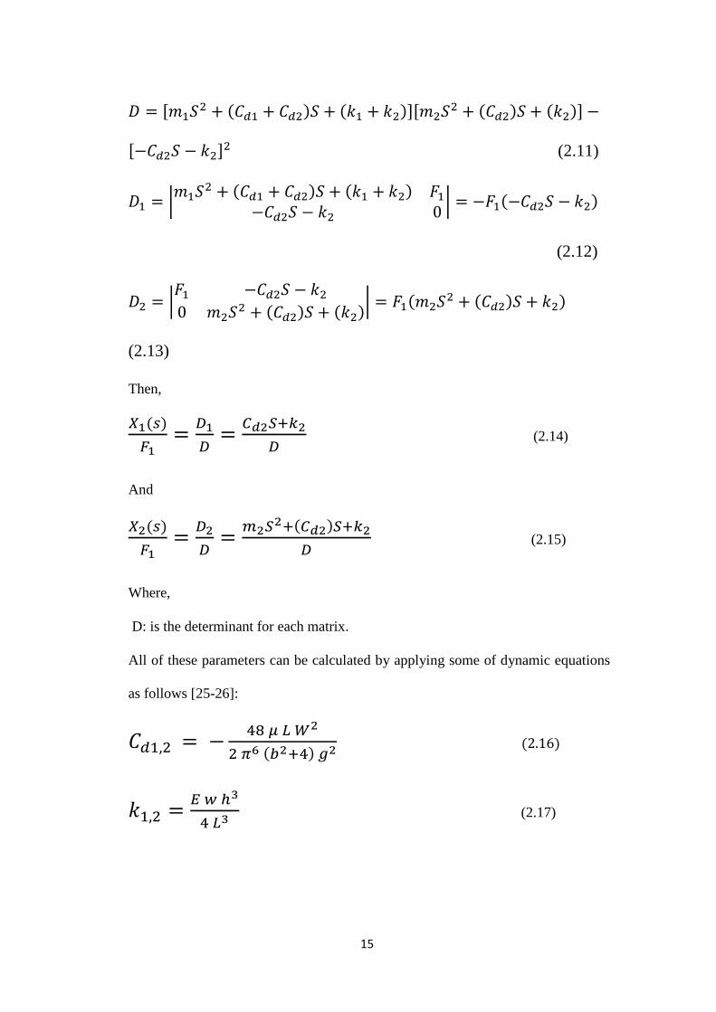
All of these parameters can be calculated by applying some of dynamic equations
as follows [25-26]:
𝐶𝑑1,2 = −48 𝜇 𝐿 𝑊2
2 𝜋6 (𝑏2+4) 𝑔2 (2.16)
𝑘1,2 =𝐸 𝑤 ℎ3
4 𝐿3 (2.17)
16
For equation (2.16), the viscosity of the poly-silicon material is 5*10^-4 N.s/m2.
The width to length ratio denoted by b. In equation (2.17), the modulus of
elasticity for the poly-silicon material is 160 GPa.
All of these equations are solved. To reach the general formula for the system
displacements, the numerical solution is found using MATLAB program.
The system solution was based on the Laplace transformation rules. The Laplace
transformation for the first and second derivatives shown in the following
equations:
ℒ(��(𝑡)) = 𝑠2ℒ(𝑥(𝑡)) − 𝑠𝑥(0) − ��(0) (2.18)
ℒ(��(𝑡)) = 𝑠ℒ(𝑥(𝑡)) − 𝑥(0) (2.19)
x(0) and x(0) are the initial displacement and velocity for the micro-mirror
system.
The maximum displacement is shown in the figure below. This displacement is
due to sinusoidal input. The maximum displacement for the inner plate is
4.2136×10⁻⁴
N at a frequency of 5.9125×10³ Hz. This displacement occurred at100
V actuating voltage.

17
Figure 2.2: mathematical results of response of the system.
The range of actuating voltage is taken from 50 to 150 V for the same properties
and the same type of signals. The maximum displacement resulted in the following
figure.

18
Figure 2.3: Response of the system under different values of voltage in
mathematical model.
2.2 Simulink Model
Simulink is the way to model, simulate and analyze the dynamics systems. The
simulink can describe the behavior of the linear and non linear systems from each
block or component it. Also, Simulink can model the continuous, discrete time and
both of them together.
Many of engineers and Scientists use the simulink tool to solve real problems in
science and industry such as signal processing, communications, aerospace and
other applications.
In this thesis, a micro-mirror model is built and simulated using mathematical
integration method from the simulink menu in MATLAB program. Initially, the
input was defines then integrate the model functions and show the mode output
19
referring to the equations of motion (2.1 and (2.2) in section 2.1. Sine wave signal
is the input of the model. There are other types of input signals such as band white
noise, step and ramp inputs. Many inputs for the model were investigated to see
the effect of noise signal on the system. Then, we integrate the two degree of
freedom system in a mathematical model functions using simulink tool as shown
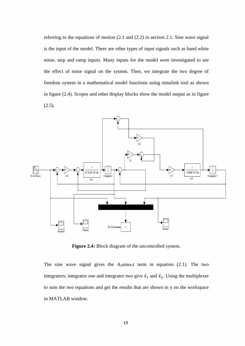
in figure (2.4). Scopes and other display blocks show the model output as in figure
(2.5).
Figure 2.4: Block diagram of the uncontrolled system.
The sine wave signal gives the A0sinω1t term in equation (2.1). The two
integrators; integrator one and integrator two give ��1 and ��2. Using the multiplexer
to sum the two equations and get the results that are shown in y on the workspace
in MATLAB window.
20
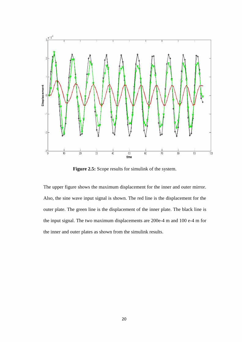
Figure 2.5: Scope results for simulink of the system.
The upper figure shows the maximum displacement for the inner and outer mirror.
Also, the sine wave input signal is shown. The red line is the displacement for the
outer plate. The green line is the displacement of the inner plate. The black line is
the input signal. The two maximum displacements are 200e-4 m and 100 e-4 m for
the inner and outer plates as shown from the simulink results.

21
Chapter Three: Finite Element Simulation
3.1 FEM Definition
FEM (Finite Element Method) is a method used to give static and dynamic
analysis for any mechanism. FEM was developed in 1943 to obtain approximate
solutions to vibration systems. FEM are used in many engineering applications
such as mechanical/civil/aerospace engineering, structural analysis,
electromagnetic, biomechanics, aeromechanics and etc.
The advantages of FEM are removing unnecessary material, eliminate failures and
it’s cheaper faster than fabricating and testing an actual parts as well as still gives
an accurate results. Also, most structural engineering calculation methods assume
that material remains in the linear elastic range but the FEM is Performing a
nonlinear analysis of a structure can help ensure that a sudden catastrophic failure
does not occur without warning of structural distress. In spite of the great efficient
of FEM, the errors of computer analysis must be kept in mind. The magnitude of
this error is determined according to the desired output.
There are two types of analysis in FEM, 2-D and 3-D modeling. The procedure of
FEM is divides into three steps. Firstly, Preprocessing step are build FE model,
loads and constrains. Secondly, FE solver is assembles and solves the system of
equations. Finally, Post processing is sort and displays the results. It needs a fast
computer to used 3-D modeling for more accurate but if you don’t want a high
accurate results and having a slow computer to run, you will use a normal
computer.

22
FEM consists of a complex system of points. These points are called nodes. The
summation of nodes makes a mesh as shown in figure (3.1). This mesh contains
the material and structural properties which define how the structure will react to
certain loading conditions. FEM is the most widely method in engineering to find
the stresses and displacement of the structures and it’s integrated with CAD/CAM
applications.
Figure 3.1: Micro-Mirror mesh diagram.
3.2 FEM in Micro-Mirror Design
We build my design as shown in fig.3.2. The two plates move up and down
depending on electrostatic force applied on it. The electrostatic force vary with the
actuating voltage that’s we applied. When the voltage increase the force will be
increased. Also, the area of the mirror and the air gap distance between the mirror
plate and electrodes effect on the magnitude of force. The type of material is poly-

23
silicon. Poly-silicon is the most used material in micro devices. Pro-mechanical
program are used to draw, analyze and simulate mirror device.FEM simulation
results are shown in fig.3.3. We can obtain from this figure the maximum
displacement that occurs at 100 V is 153.3 µm displacements that mean 8.82°
tilting angle achieved.
Figure 3.2: The displacement plot from simulation.

24
Figure 3.3: Response of the system under different values of voltage resulted from
Pro-Mechanica.
Figure 3.4: The deformed mirror.

25
The micro-mirror is drawing in Pro-Mechanica program. The material of the
mirror is assigned with there is properties like, the density, ultimate tensile stress,
ultimate shear stress and other properties. All of these properties are listed as
follows in table 3.1. The electrostatic force is acting on the bottom surface. The left
side of the beams that’s connecting on the mirror is fixed as shown in figure (3.4).
When we simulate the designed drawing the mirror moves up to reach the
maximum displacement depending on the actuating force applied on it.
Table (3.1): Material properties of poly-silicon
Material Properties “Poly-Silicon”
Type Isotropic
Density 2.33×10⁻¹²
(g/µm3)
Young Modulus 160 (GPa)
Poisson’s Ratio 0.221
Ultimate Tensile Stress 1.2 (GPa)
26
Chapter Four: Control Design
4.1 Introduction to PID controller
In any mechanism in the life, there are some differences between mathematical
models and simulated programs. To solve this issue, some of controllers are used.
In this thesis, we found 33% percentage error between mathematical model of
micro-mirror device and the simulation results as shown in figure (5.1). PID
(Proportional Integral Derivative) controller used to decrease the error and
minimize it as much as possible.
PID controllers are the most used today in feedback control of industrial systems.
Almost, all PID controllers depend on microprocessor so it has wide range of
applications. The basic structure of the PID controllers is shown in figure (4.1).
The PID controller used as a compensator. The P, I and D parameters are
determined where P is proportional to error at time t, I is proportional to integral of
the error at time t as well as D is the proportional to derivative of the error at time
t. The PID controller takes the past, present and future error into consideration.

27
Figure 4.1: PID controller structure.
The control system represented as follows in figure (4.2).
Figure 4.2: Block diagram of the PID controller system.
the input signal (F) inters to the system (G) for processing and control it. The C
and H are controller and feedback signal, respectivly. For our model, C expresses
the PID controler.
PID control is selected in this design to make high performance because the PID
controller make the steady state error is zero but the other controllers such as P or

28
PD are used for simple design and easy maintenance, also it gives low
performance compared with PID controller.
4.2 Control of Micro-Mirror Device
The mathematical description of the PID transfer function for second degree of
freedom is [28]:
T(s) = Kp(1 +1
KI.S+ KD. s) (4.1)
And the transfer function of the second order system for the outer mirror is:
T1(s) =
m2S2+Cd2S+K2
m1m2S4+(m1Cd2+m2Cd1+m2Cd2)S3+(Cd1Cd2+m2K1+m2K2)S2+(Cd1Kd2+Cd2K1)S+K1K2
(4.2)
T2(s) =
m1S2+(Cd1+Cd2)S+(K1+K2)
m1m2S4+(m1Cd2+m2Cd1+m2Cd2)S3+(Cd1Cd2+m2K1+m2K2)S2+(Cd1Kd2+Cd2K1)S+K1K2
(4.3)
The characteristic equation to calculate the PID parameters for the outer plate is
[29]:
1 + 𝑇(𝑠)𝑇1(𝑠) = 0 (4.4)
Also,
29
The characteristic equation to calculate the PID parameters for the inner plate is
[30]:
1 + 𝑇(𝑠)𝑇2(𝑠) = 0 (4.5)
When we substitute equation (1) and (2) in (3), the PID parameters can be
determined as follows [31]:
𝐾𝑝 =(1+10𝜁𝑡
2)𝜔𝑛𝑡2
𝜔𝑛2 − 1 (4.6)
𝐾𝐼 =𝐾𝑝𝜔𝑛
2
5𝜁𝑡𝜔𝑛𝑡3 (4.7)
𝐾𝐷 =7𝜁𝑡𝜔𝑛𝑡−2𝜁𝜔𝑛
𝐾𝑝𝜔𝑛2 (4.8)
Also, we found these values using MATLAB tool. SISO MATLAB tool gives an
initial guess for Kp, KI and KD.
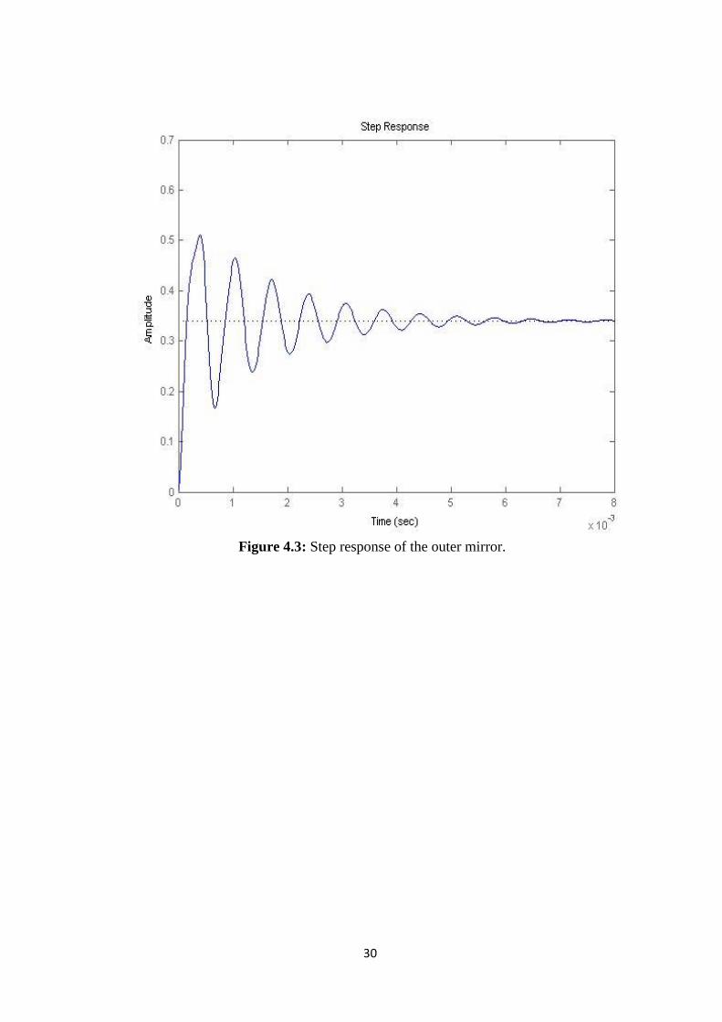
The step responses of the open loop that’s tuning by SISO tool for the inner and
outer mirror are shown in figure (4.2) and (4.3):
30
Figure 4.3: Step response of the outer mirror.

31
Figure 4.4: Step response of the inner mirror.
The step responses that are get us from the transfer functions for the inner and
outer mirror are shown in figure (4.4) and (4.5):

32
Figure 4.5: Step response of the outer mirror

33
Figure 4.6: Step response of the inner mirror.
From the root locus plot, we can determine the stability f the system as shown in
figure (4.6):

34
Figure 4.7: Root locus of the system.
Figure 4.8: Bode plot of the system.
35
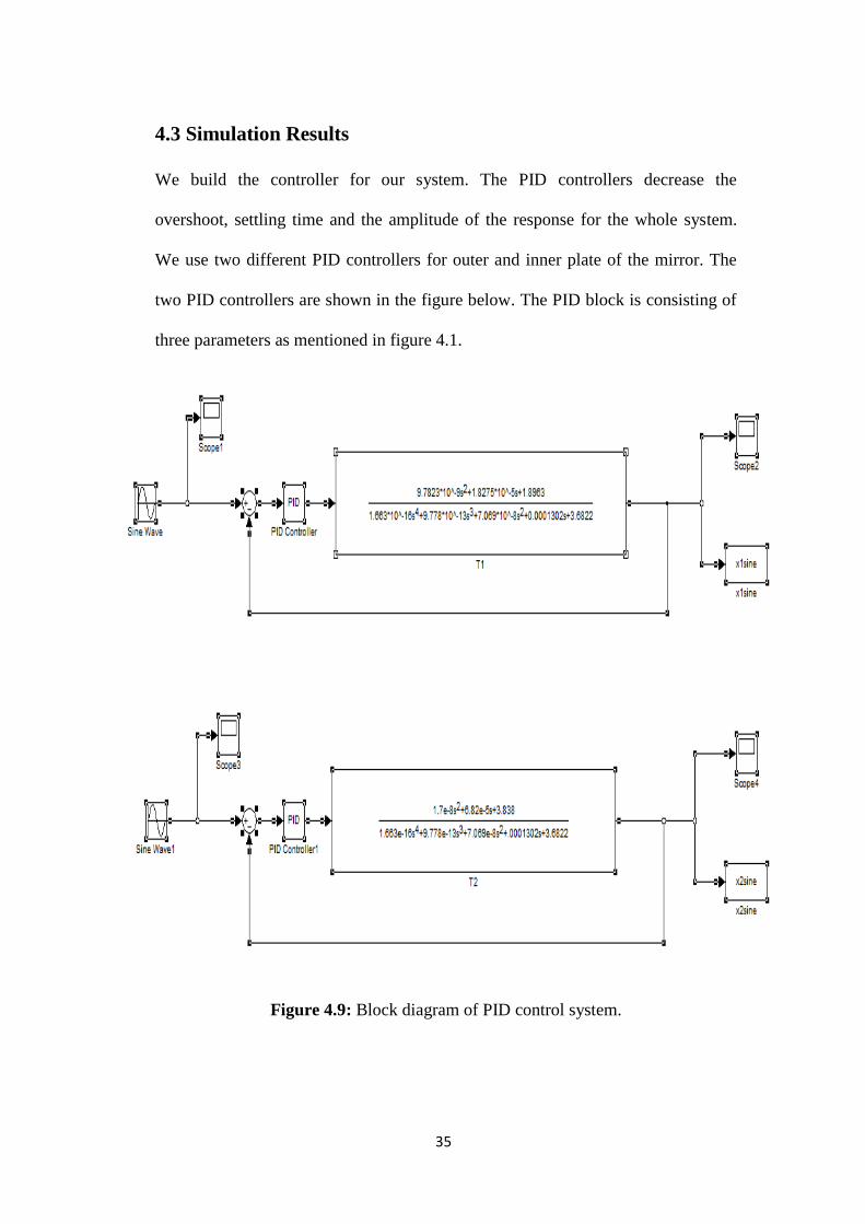
4.3 Simulation Results
We build the controller for our system. The PID controllers decrease the
overshoot, settling time and the amplitude of the response for the whole system.
We use two different PID controllers for outer and inner plate of the mirror. The
two PID controllers are shown in the figure below. The PID block is consisting of
three parameters as mentioned in figure 4.1.
Figure 4.9: Block diagram of PID control system.

36
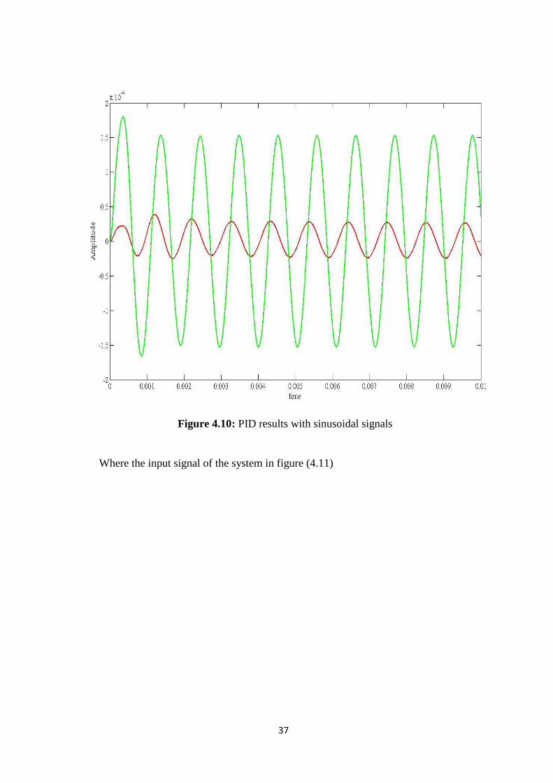
After we add PID controller on the system, the response has enhanced to be better.
The settling time is decreased as well as the overshoot is decreased also. The
response after adding PID controller shown in figure(4.10).
The PID controller gives a better performance. The block diagram in figure (4.9)
presents the sine wave signal with 2.223×10⁻⁴
amplitude and 5.9125×10³ natural
frequency that’s acting in a micro-mirror device. The transfer functions that’s
expresses the displacement of the system are mentioned. The PID controller is
tuning the system to get better performance and minimize the error. The PID
parameters are getting it using trial and error method. Initially, we depend on the
SISO initial guess to determine it using Ziegler-Nichols tuning formula. Then, we
have tried around these values to reach to minimum error. As a result, the PID
parameters tuning is difficult. It’s necessary to select the PID parameters carefully
whenever the characteristics of the system change which is caused by changing in
operation conditions. Tuning is worked to adjust the parameters of the controller to
satisfy the desired property. The tuning method used in our design is Ziegler–
Nichols method.
Where ζt is the target damping ratio and ωnt the target undamped natural
frequency. These parameters are determined from the design specifications.
37
Figure 4.10: PID results with sinusoidal signals
Where the input signal of the system in figure (4.11)
38
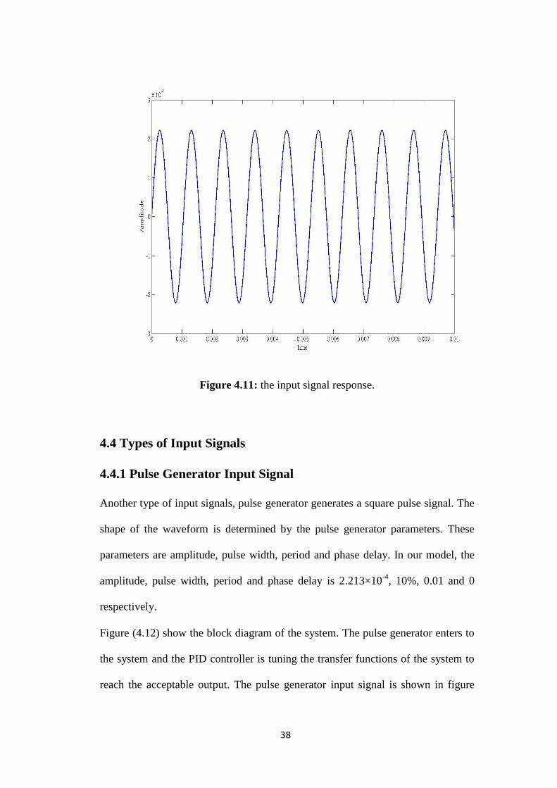
Figure 4.11: the input signal response.
4.4 Types of Input Signals
4.4.1 Pulse Generator Input Signal
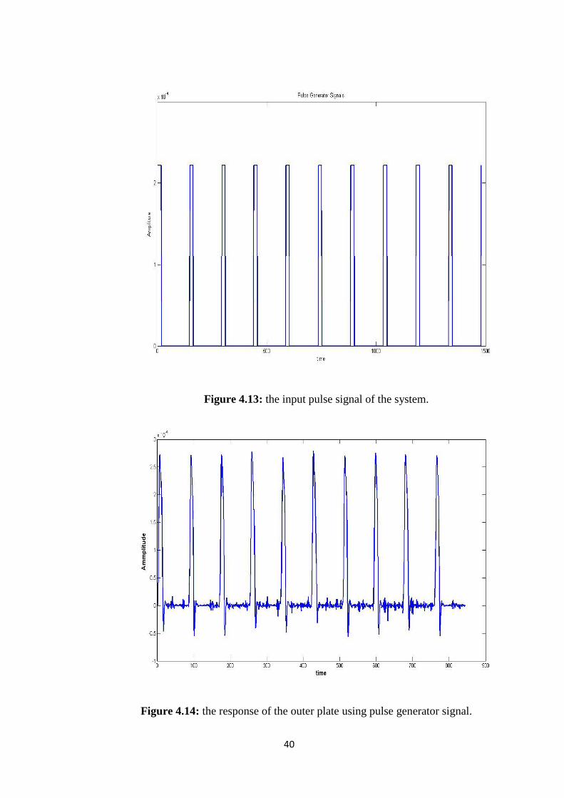
Another type of input signals, pulse generator generates a square pulse signal. The
shape of the waveform is determined by the pulse generator parameters. These
parameters are amplitude, pulse width, period and phase delay. In our model, the
amplitude, pulse width, period and phase delay is 2.213×10⁻⁴
, 10%, 0.01 and 0
respectively.
Figure (4.12) show the block diagram of the system. The pulse generator enters to
the system and the PID controller is tuning the transfer functions of the system to
reach the acceptable output. The pulse generator input signal is shown in figure

39
(4.13) with amplitude 2.213×10⁻⁴
. After adding the PID controller to enhance the
system, the result is shown in figure (4.14), (4.15).
Figure 4.12: Block diagram of the system using pulse generator signal.
40
Figure 4.13: the input pulse signal of the system.
Figure 4.14: the response of the outer plate using pulse generator signal.
41
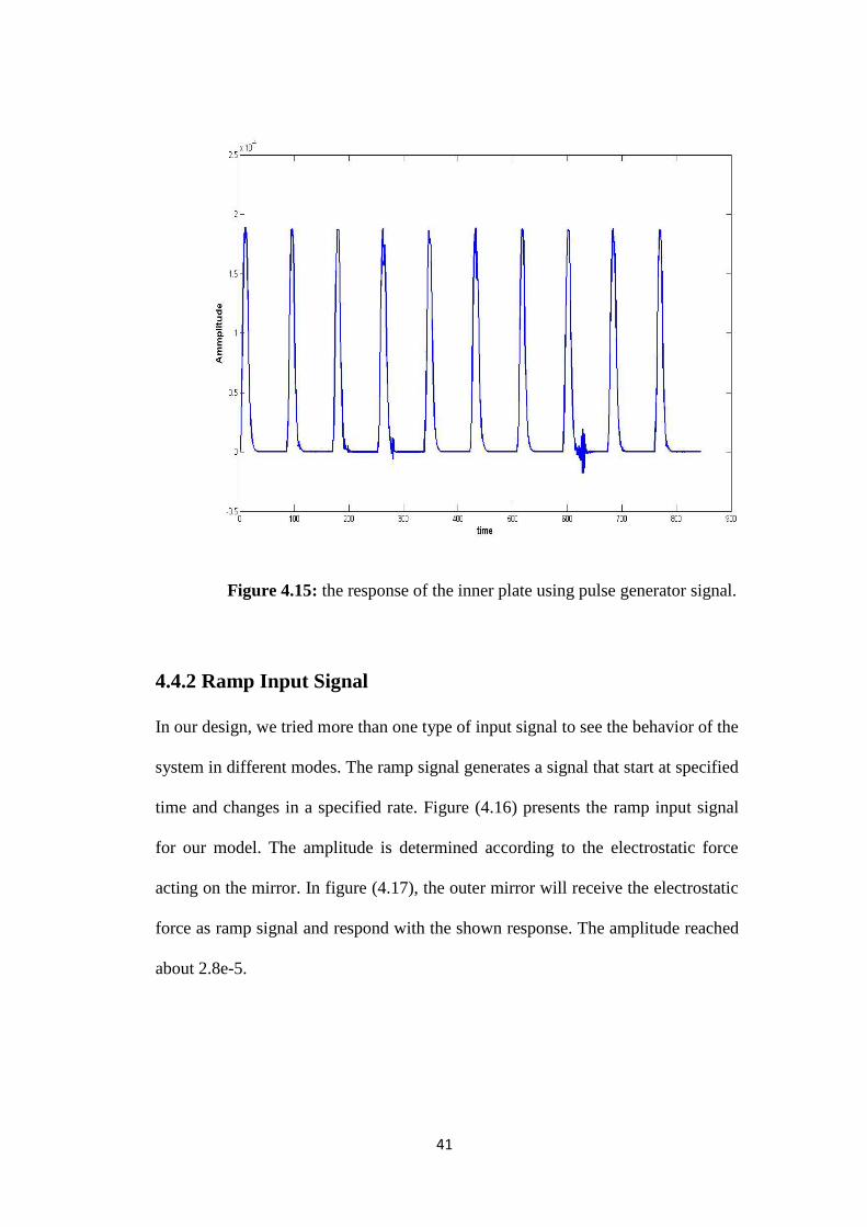
Figure 4.15: the response of the inner plate using pulse generator signal.
4.4.2 Ramp Input Signal
In our design, we tried more than one type of input signal to see the behavior of the
system in different modes. The ramp signal generates a signal that start at specified
time and changes in a specified rate. Figure (4.16) presents the ramp input signal
for our model. The amplitude is determined according to the electrostatic force
acting on the mirror. In figure (4.17), the outer mirror will receive the electrostatic
force as ramp signal and respond with the shown response. The amplitude reached
about 2.8e-5.

42
Figure 4.16: the response with ramp input signal.
Figure 4.17: the response of the outer plate with ramp input signal.

43
4.5 Noise Signals
4.5.1 band-limited white noise signal
The model response changes according to different type of noise that’s possible to
expose. In this thesis, we study the types of noises and input signals to observe the
output response. Then, modifying it to reach the stable state and getting the desired
output.
The band-limited white noise signals generates normally distributed random
numbers that’s introducing the white noise into continuous system.
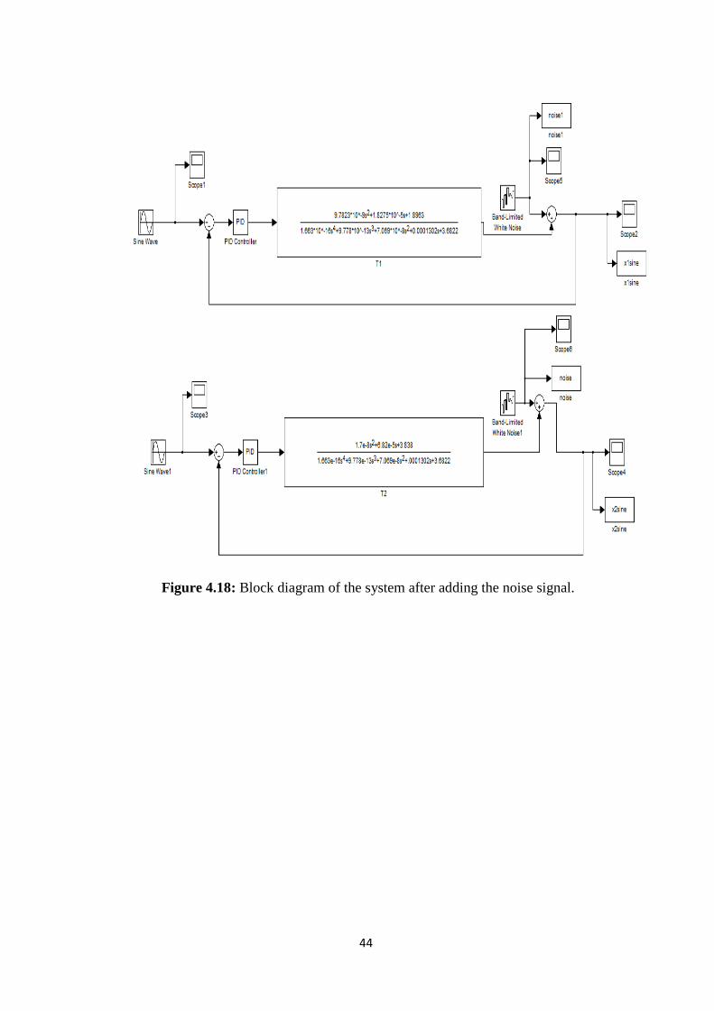
Figure (4.18) presents the block diagram of the white noise signal of the whole
system. Using white noise signal, the response of the system with PID controller
shown in figure (4.20). We observe that the output response not affected with noise
signal. It means that the PID controller works right. The noise signals shows in
figure (4.19) with 10% from the original signal.
44
Figure 4.18: Block diagram of the system after adding the noise signal.
45
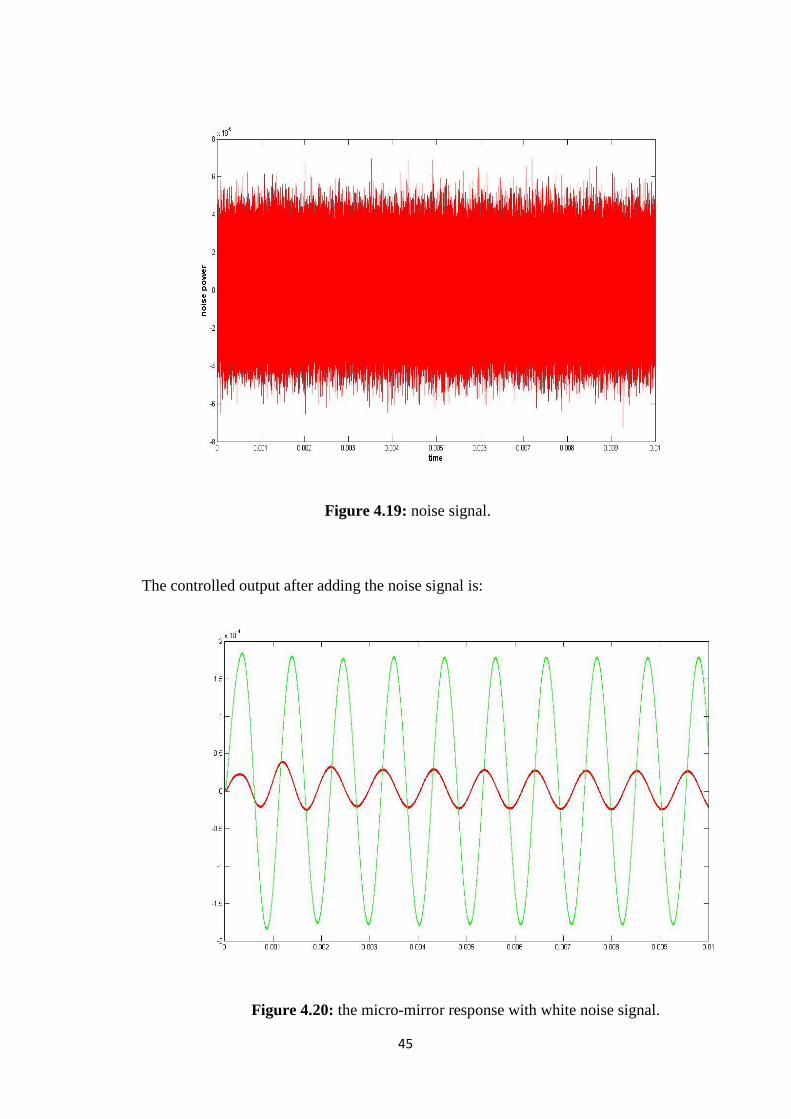
Figure 4.19: noise signal.
The controlled output after adding the noise signal is:
Figure 4.20: the micro-mirror response with white noise signal.
46
4.5.2 Step response noise
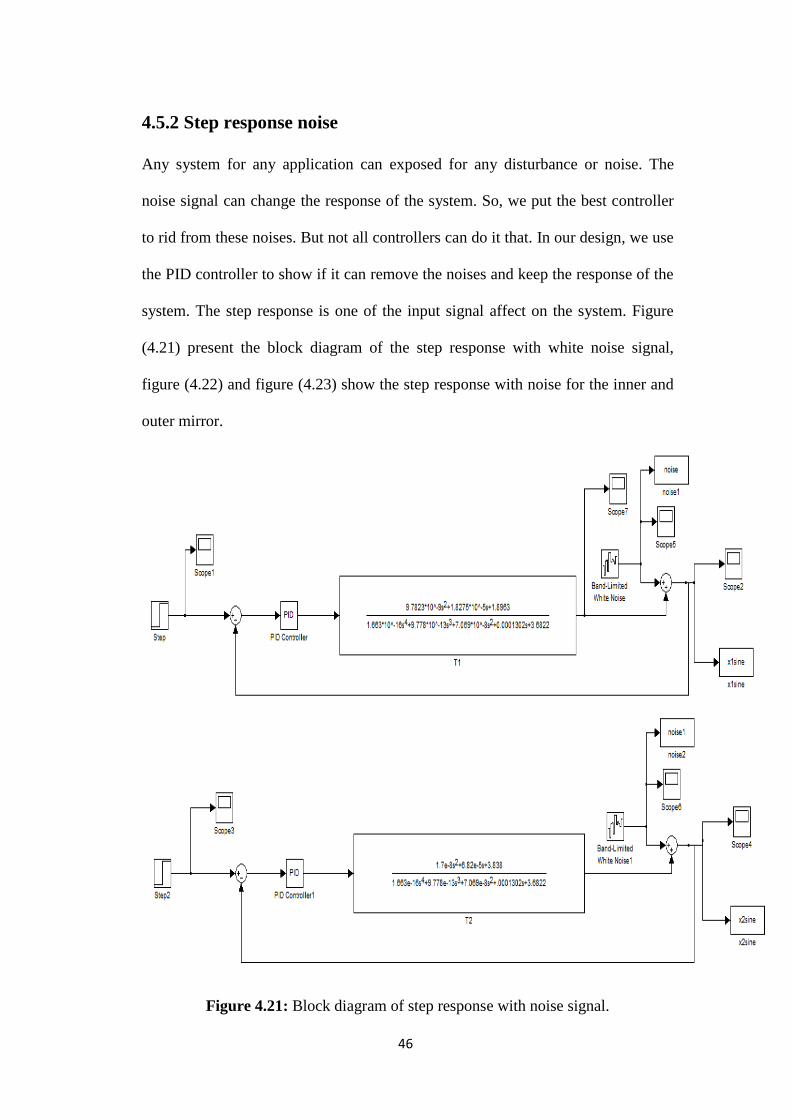
Any system for any application can exposed for any disturbance or noise. The
noise signal can change the response of the system. So, we put the best controller
to rid from these noises. But not all controllers can do it that. In our design, we use
the PID controller to show if it can remove the noises and keep the response of the
system. The step response is one of the input signal affect on the system. Figure
(4.21) present the block diagram of the step response with white noise signal,
figure (4.22) and figure (4.23) show the step response with noise for the inner and
outer mirror.
Figure 4.21: Block diagram of step response with noise signal.

47
Figure 4.22: Step response with noise of the outer mirror.
Figure 4.23: Step response with noise of the inner mirror.

48
Chapter Five: Discussion
For any system in nature, there are some differences between the mathematical
model that is describing the system and the simulated results that have come from
computer programs. These differences take place because the mathematical model
presents the system in ideal case without any external stimulation such as
disturbance or noise occurs on the system. But the simulation shows the motion of
the system as it is near to reality.
In our model, we simulate the mirror on Pro-Engineering program and we
described the system in its mathematical model as a two degree of freedom as
followed above in section 2. We observe that when we take more than one value
for the actuating voltage and compute the resulted angle in mathematical model
and simulation, the tilting angle is increase as well the actuating voltage is
increasing also as shown in figure 5.1. The error between the mathematical results
and simulation results are shown in figure 5.2.

49
Figure 5.1: the maximum tilting angle at different values of voltage.
We can see from the previous figure, the maximum tilting angle is 8.82° at 100V.
The angle will increase as the voltage increases. At 50V the angle is about 2.2°.
also, at 130V the angle is 15°.

50
Figure 5.2: The error between pro-mechanica and mathematical model results.
After using PID controller, the error became smaller than before as shown in figure
(19).
The maximum displacement in the mathematical model results was about 400µm
but in the simulation results was 153.3µm. Therefore, the PID controller is used.
After that, the error becomes 0.5%. Also, the overshoot for the step response of the
outer mirror is 64% and 62.2 for the inner mirror before using the PID controller
shown in the figure (5.2) and (5.3).
The proportional controller (P) responsible for decreases the error between the two
values of mathematical and simulating results. The integral term of the PID
controller (I) reduces the steady state error to zero. The derivative controller (D)
decreases the value of the overshoot of the system.

51
Figure 5.3: the overshoot of the step response of the inner plate.
Figure 5.4: the overshoot of the step response of the outer plate.

52
The PID controller decreases the overshoot to 0.05% for the inner plate and 0.03%
for the outer plate.
53
Chapter Six: Conclusion
The new design of micro-mirror device driven by electrostatic force has been
demonstrated. This design can deflect the angle in to steps to achieve larger
reflection than the others design that’s made from the same material and having the
same properties. The analytical design and the simulation results have been
described. The whole system move in two natural frequencies depends on the
difference in spring constants of the inner and outer beams although this difference
is small so, it doesn’t affect on the overall natural frequency of the system. Also,
the damping ratio of two plates doesn’t make a big effect on the response of the
system because it’s almost equal to zero. From the numerical and FE models, we
can conclude that when the increasing the applied voltage will increase the tilting
angle. The maximum displacement is 153.33 µm at 100 V means that the tilting
angle is 8.82°. The whole system move in two natural frequencies depends on the
difference in spring constants of the inner and outer beams although this difference
is small so, it doesn’t affect on the overall natural frequency of the system.
PID controller is used to reduce the steady state error to zero. So, PID controller
gave high performance of the system. PID control enhanced the whole system and
reached it to the desired output. The error is become about 0.5% as mentioned after
using controller.
54
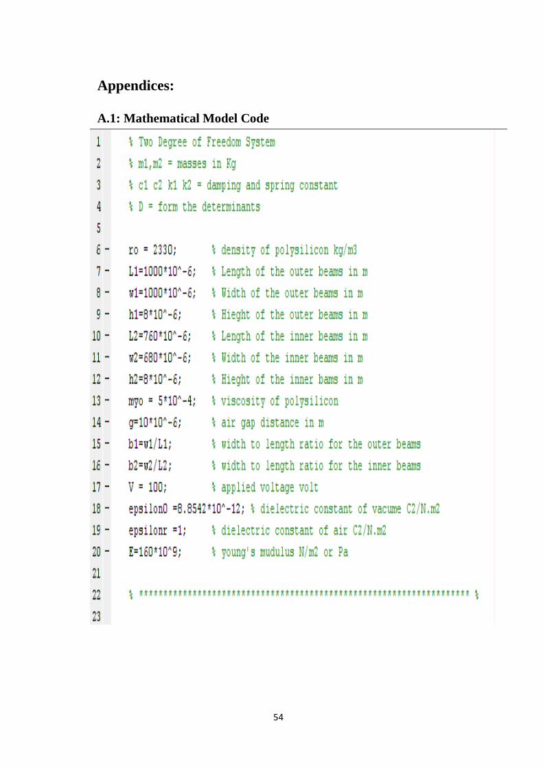
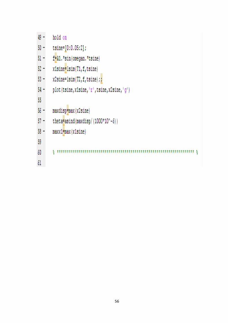
Appendices:
A.1: Mathematical Model Code

55
56
57
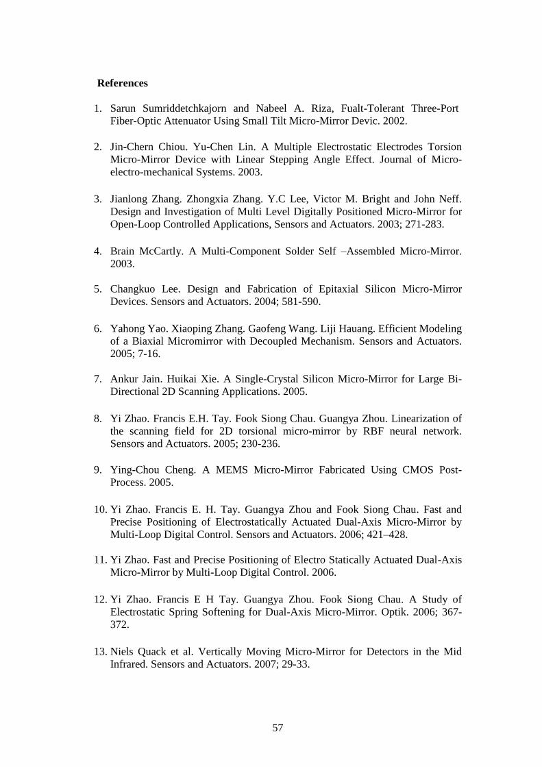
References
1. Sarun Sumriddetchkajorn and Nabeel A. Riza, Fualt-Tolerant Three-Port
Fiber-Optic Attenuator Using Small Tilt Micro-Mirror Devic. 2002.
2. Jin-Chern Chiou. Yu-Chen Lin. A Multiple Electrostatic Electrodes Torsion
Micro-Mirror Device with Linear Stepping Angle Effect. Journal of Micro-
electro-mechanical Systems. 2003.
3. Jianlong Zhang. Zhongxia Zhang. Y.C Lee, Victor M. Bright and John Neff.
Design and Investigation of Multi Level Digitally Positioned Micro-Mirror for
Open-Loop Controlled Applications, Sensors and Actuators. 2003; 271-283.
4. Brain McCartly. A Multi-Component Solder Self –Assembled Micro-Mirror.
2003.
5. Changkuo Lee. Design and Fabrication of Epitaxial Silicon Micro-Mirror
Devices. Sensors and Actuators. 2004; 581-590.
6. Yahong Yao. Xiaoping Zhang. Gaofeng Wang. Liji Hauang. Efficient Modeling
of a Biaxial Micromirror with Decoupled Mechanism. Sensors and Actuators.
2005; 7-16.
7. Ankur Jain. Huikai Xie. A Single-Crystal Silicon Micro-Mirror for Large Bi-
Directional 2D Scanning Applications. 2005.
8. Yi Zhao. Francis E.H. Tay. Fook Siong Chau. Guangya Zhou. Linearization of
the scanning field for 2D torsional micro-mirror by RBF neural network.
Sensors and Actuators. 2005; 230-236.
9. Ying-Chou Cheng. A MEMS Micro-Mirror Fabricated Using CMOS Post-
Process. 2005.
10. Yi Zhao. Francis E. H. Tay. Guangya Zhou and Fook Siong Chau. Fast and
Precise Positioning of Electrostatically Actuated Dual-Axis Micro-Mirror by
Multi-Loop Digital Control. Sensors and Actuators. 2006; 421–428.
11. Yi Zhao. Fast and Precise Positioning of Electro Statically Actuated Dual-Axis
Micro-Mirror by Multi-Loop Digital Control. 2006.
12. Yi Zhao. Francis E H Tay. Guangya Zhou. Fook Siong Chau. A Study of
Electrostatic Spring Softening for Dual-Axis Micro-Mirror. Optik. 2006; 367-
372.
13. Niels Quack et al. Vertically Moving Micro-Mirror for Detectors in the Mid
Infrared. Sensors and Actuators. 2007; 29-33.

58
14. Sangtak Park. So-Ra Chung. John T.W. Yeow. A Design Analysis of Micro-
mirrors in Stacked Configurations with Moving Electrodes. International
Journal on Smart Sensing and Intelligent Systems. 2008.
15. Niels Quack et al. A Comb Drive Actuated Vertically Moving Micro-Micro-
mirror for tunable Mid Infrared Resonant Cavity Enhanced Detectors.
Microelectronic Engineering. 2009; 1243-1246.
16. A. A. Kujpers et al. Towards Embedded Control for resonant Scanning MEMS
Micro-Mirror. Procedia Chemistry. 2009; 1307-1310.
17. Fangrong Hu. Jun Yao. Chuankai Qiu. Hao Ren. A MEMS Micro-Mirror
Driven by Electrostatic Force, Journal of Electrostatics. 2010; 237-242.
18. Kah How. Takeshi Kobayashi. Fu-Li Hsiao and Chengkuo Lee.
Characterization of Piezoelectric PZT beam actuators for driving 2D Scanning
Micro-Mirrors. Sensors and Actuators. 2010; 336-347.
19. Fangrong Hu. Yalu Tang. Yixian Qian. Design of a MEMS micro-mirror
actuated by electrostatic repulsive force. Optik. 2010.
20. William J. Palm III. Model, analyze and solve vibration Problems Using
Modern Computer Tools. University of Rhode Island.
21. William J. Palm III. Model, analyze and solve vibration Problems Using
Modern Computer Tools. University of Rhode Island.
22. William J. Palm III. Model, analyze and solve vibration Problems Using
Modern Computer Tools, University of Rhode Island.
23. Sangtak Park. So-Ra Chung. John T.W. Yeow. A Design Analysis of Micro-
mirrors in Stacked Configurations with Moving Electrodes. International
Journal on Smart Sensing and Intelligent Systems. 2008.
24. Araki M. PID Control. Kyoto University. Control System. Robotics and
Automation. Japan.
25. Somasundaram Velummylum. The Use of Maple and Laplace Transformation
in Solving Initial Value problem. Calvin University. Department of
Mathematics and Computer Science. 2003.
26. Araki M. PID Control. Kyoto University. Control System. Robotics and
Automation. . Japan.
27. Yi Zhao. Francis E. H. Tay. Guangya Zhou. Fook Siong Chau. Fast and precise
positioning of electrostatically actuated dual-axis micro-mirror by multi-loop
digital control. Sensors and Actuators. 2006; 421-428.

59
28. Yi Zhao. Francis E. H. Tay. Guangya Zhou. Fook Siong Chau, Fast and precise
positioning of electrostatically actuated dual-axis micro-mirror by multi-loop
digital control. Sensors and Actuators. 2006; 421-428.
29. Yi Zhao. Francis E. H. Tay. Guangya Zhou. Fook Siong Chau, Fast and precise
positioning of electrostatically actuated dual-axis micro-mirror by multi-loop
digital control. Sensors and Actuators. 2006; 421-428.

60
الهيدروستاتيكيه القوه باستخدام تشغل الصغر متناهية بمرآة وتحكم تصميم
.الجراح محمد عبدالله آياتاعداد:
الملخص
يتم تقديم تصميم جديد لجهاز المرآة الدقيقة والتحليل العددي في هذه الأطروحة. وتستخدم
زاوية انحراف في إطار الجهد المنخفض تطبيقها. يتم تطبيق أشعة ضعيفة إلى أقصى حد من
العنصر طريقة القوة الكهروستاتيكية. يذكر نموذج نظري لوصف استجابة النظام. يستخدم
° 13.3لمحاكاة المرآة وجعل التوتر وتحليل التشريد. زاوية انحراف الأقصى هو المحدود
× 780، و الخارجية ميكرومتر لوحة المرآة 8× 1000× 1000فولت مع 100عند
× 600ميكرون، و 8× 40× 750ميكرومتر لوحة المرآة الداخلية فضلا عن 8× 760
على التوالي. متطلبات الأجهزة ةوالداخلي ةالخارجي الزنبركات أعمدةميكرون أبعاد 8× 20
المرآة الدقيقة هي على وجه التحديد للسيطرة على انعكاس لأشعة الحادث. التحدي هو توفير
وزيادة قيمة الحد الأقصى لزاوية القوة منالحد الأدنى باستخدام الميلانلزاوية دقيق تحكم
يقترح آلية جديدة لتحقيق زاوية الميل. ،متطلباتال هذه نظام يمكن أن تقدم. لتحقيقالإمالة