Embed Size (px)
Citation preview

Design and Construction of the Capilano Cliffwalk
Kent LaRose, M.A.Sc., P.Eng., Regional Manager Bridges, Morrison Hershfield Ltd. (presenting)
Scott Loptson, P.Eng., Senior Bridge Engineer, Morrison Hershfield Ltd.
Duncan C. Wyllie, M.S., P.Eng., Principal, Wyllie Norrish Rock Engineers Ltd.
Stuart Masterson, M.Eng., Sr. Survey Party Chief, McElhanney Consulting Services Ltd.
Paper prepared for presentation at the Session
Bridges – Successes: Let’s Build on Them
of the
2011 Annual Conference of the Transportation Association of Canada
Edmonton, Alberta

i
Abstract The Cliffwalk at the Capilano Suspension Bridge Park in North Vancouver truly is a structure that hangs off a cliff. The 213 m long, 0.5 m wide steel walkway with timber decking is cantilevered some 3 m from the face of the cliff and considered to be the first of its kind in the world. It will provide visitors access to previously undreamed areas of the park. Areas that historically only experienced rock climbers would be able to enjoy plus the structure acts as a medium for the education of visitors to the water/erosion cycle through a series of interactive displays. It consists of a series of 8 bridges, 5 stairs, 7 platforms (two with glass decks) and a cable supported curved bridge that traverse the eastern face of the Capilano Canyon and only require 11 sq. m of foundation area.
The construction planning and design of the structure was truly a collaborative effort, with input at the design stage from the surveyors, constructor, owner, steel fabricator and multiple engineering disciplines. The design process started with a field reconnaissance of the rock face by rappelling to determine best probable foundation locations and overall route location, all while accounting for tree locations. Suitable locations for foundations were established based on visual observations of the rock face. A total of 510 m of rock anchors of three different types were used. A total of 12 distinct alignments were designed prior to finalizing the alignment.
Rock fall risk management was identified as an early design constraint. To mitigate pedestrian exposure to any stray rock fall, the majority of the walkway is cantilevered from the rock face by 3.0 m. Rock management is also provided by the construction of a reinforced soil slope at the crest of the cliff, stabilizing the cliff face with rock bolts and the construction of rock fencing wherever the field testing of rock trajectories indicated.
The fabrication/erection technique developed for the project was said to be ground breaking by the steel fabricator. The detailing of the geometry of all the steel work was based on the surveyed locations of the foundation base plates that were installed and then surveyed in the field. The field coordinates of the foundation plates were then used to define the geometry using Prosteel, a 3D steel detailing program, without the ability to dry fit any pieces in the shop. The final misclosure of the last joint in the 213 m long run was only 15 mm.
Construction access was very limited and the original design needed to limit the weight of individual members to allow erection using only manpower, with only the curved, cable supported steel bridge and a couple of the straight bridge segments requiring erection with a small crane.

1
Introduction While rappelling down the eastern cliff face of the Capilano Canyon, John Stibbard, Vice President of Operations for the Capilano Suspension Bridge Park (CSB) in North Vancouver, made the realization that they needed a way for guests to experience the cliff face in the park while having minimal impacts to the environment. The challenge was that it was not feasible to safely provide over 750,000 annual guests with access to the cliff face using standard rock climbing techniques for a number of reasons: it would destroy the sensitive flora/fauna on the cliff face; the logistics of accommodating that many people were staggering; and it presented many safety and liability concerns. Another physical means needed to be found in order to provide guest access to the cliff face.
The Cliffwalk structure is the culmination of several years of brainstorming and innovative design. It provides access to areas of the park that historically only experienced rock climbers would be able to enjoy, plus, the structure acts as a medium for the education of visitors. The David Suzuki Foundation is a partner of the Cliffwalk and broadens the guests’ experience with expert input into the interactive signage relating to the water cycle and its interaction with forming the canyon, aquatic life, flora and fauna. It also serves as a means to passively control the distribution and flow of park guests and has allowed the owner to reclaim over 2 acres of land into usable park space by terraforming an old gravel landing and installing a new walkway and water features.
There were many difficulties to overcome on this project. One of the first was how to obtain the District of North Vancouver’s approval for a building permit for such a unique structure. How would the structure be constructed in a rainforest, with minimal impact on the environment, with limited construction access, all the while providing a safe structure that was envisioned to be thin, slender, light & airy, and “thrilling”, and provides an experience that was comparable to the other structures in the park? What about the rock fall hazards or constructing in a park setting without negatively impacting the guests’ experience? What alignment should the Cliffwalk take and exactly where on the cliff face should the structure be located? These are only some of the many technical issues that needed to be overcome during the project.
Somewhat similar structure types have been constructed before, like the El Caminito del Rey (the King’s little pathway) in Spain (constructed 1901-1905 as a means for workers to move materials during the construction of a hydroelectric dam), but never in a privately owned park that promotes eco-educational tourism. There was no precedence for the overall structure, so a synthesis of design and construction techniques was required. The total reliance upon 3D survey data in conjunction with having to constantly update the 3D model as foundation elements were installed was considered to be ground breaking by the steel fabricator.
The critical success of the Cliffwalk is that the 213 m long, 0.5 m wide steel walkway was constructed by impacting only 11 sq. m of foundation area, including avoiding key areas of the rock face that is covered in grass, moss or ferns. Also of note is the iterative combination of survey/design/fabricate/erect used to construct the steel walkway.
The Capilano Suspension Bridge Park The Capilano Suspension Bridge (CSB) Park is located in the District of North Vancouver, 0.8 km north of the Trans-Canada Highway on Capilano Road. Figure 1 - Project Location, pictorially displays the location relative to some local features.

2
Figure 1 - Project Location
The subject site is located on the Capilano River and has land holdings on both sides of the river. The main attraction of the park for the majority of its existence has been the suspension bridge over the river. The recently constructed Treetops Adventure canopy walkway has increased the visitors’ experience by providing access to the canopy of the rain forest on the west side of the park.
The CSB currently offers a number of educational opportunities for its visitors unique to the west coast. These include First Nations culture, local history, aquatic and terrestrial life, floral/fauna of the rainforest and the rainforest canopy. Each of these has required the construction of infrastructure to provide access and at the same time conserve the natural environment of the park.
What exactly is the Cliffwalk? The Cliffwalk is akin to a catwalk and it allows visitors access down along the granite cliff on the east side of the park via a narrow walkway that is cantilevered from the cliff face. It includes the following prominent features: a spiral stairway; 8 bridge spans; 5 straight stairways; 7 observation platforms (two with glass decks complete with a baked on ceramic anti-skid coating and glass guards); a 30 m cable supported semi-circular bridge; stainless steel woven wire mesh guards; over 400 m of stainless steel handrail; and 510 m of rock anchors. At its highest point, the Cliffwalk is 90 m (30 stories) above the Capilano River.
The pedestrian movement is in one direction along the Cliffwalk structure, with an easily recognized entrance and exit. The bridges and stairs are designed to accommodate one-way, single file pedestrian movement. Similar to the suspension bridge and Treetops Adventure, access to the facility will be controlled and visitors supervised while enjoying the facility. The total length of the Cliffwalk is 213 meters with an approximate total plan area of 160 square meters. The total descent from the spiral stairs entrance of the Cliffwalk is 8.8 meters down to the curved bridge and the ascent to the exit/start of the trail system is about 17.6 m.
The intent of the design is to provide public education through a self-guided interpretive tour. The location of the walkway will also provide views of the Capilano River, thereby providing an educational opportunity to stress the importance of the hydrologic cycle for life on the planet. Other educational

3
opportunities that exist include: the geologic time scale of the canyon as it relates to a degrading river channel and erosion; the unique floral/fauna that inhabit the cliff face; and access to view of the unique forest that is at the base of the cliff.
History of Cliffwalks Walkways and roads have been cantilevered from cliff faces since ancient times to improve transportation and communication through treacherous regions. Some notable examples are outlined in the following paragraphs. A historic Canadian example of cliff walkways is found near Hells Gate in the Fraser Canyon, BC. In 1808, Simon Fraser noted traversing along cliffs in the Fraser Canyon on a series of bridges and ladders constructed by local Nlaka'pamux people.
An extensive network of timber board roads existed in the Three Gorges region in ancient China. The boards were supported on thick wooden pegs that were inserted into holes that were chiselled into the cliff face. The majority of the original roadway has deteriorated, however, some sections have survived and others have been reconstructed.
El Caminito del Rey (The Kings Little Pathway) in Spain was constructed in 1905 between Chorro Falls and Gaitanejo Falls (see Figure 2). The 1.0 meter wide walkway is up to 330 meters high. The concrete path is supported by a steel support structure that is cantilevered off of the cliff face.
Figure 2 - El Caminito del Rey, Spain
Permit Application and Data Gathering A building permit was required by the District of North Vancouver prior to the construction of the Cliffwalk. This presented a number of challenges for the project team and the District. The application permit required a topographic and cadastral survey to be conducted on which to base the application design drawings.
Survey control was established and refined throughout the initial stages of the project. For the initial topographic survey, a closed traverse was run along the base of the cliff and closed to the existing survey control at the top of the cliff. As the project progressed, additional survey control points (including several custom built cliff mounted brackets) were installed and surveyed and a least squares adjustment was performed. This survey control was used for the remainder of the project.

4
Rock face surveys are usually undertaken using an automated scanner which is set up in a stable location with clear sightlines to the cliff. The lush, dense coastal rainforest found in Capilano Canyon covers all but a few sections of the proposed walkway alignment and meant that this well established technique was impossible.
An initial topographic survey was conducted in the late summer and fall of 2009. This survey was designed to map the general features of the cliff face including any ledges, overhangs, trees, gullies, major cracks or caves that should be noted during design. The survey mapped additional features such as the top and bottom of the existing CSB wooden cantilevered deck and the foundations of the existing buildings at cliff top. In addition, a full ground profile was surveyed from the base of the cliff down to the Capilano River in the canyon bottom.
Gaining access to the cliff face and sloped ground below required the use of ladders, ropes and intense application of fall protection procedures (see Figure 3). Due to the unusual access requirements of this survey, personnel were trained in basic fall protection procedures as well as advanced vertical lifeline techniques. Throughout the project, difficult access was an issue but was overcome with a combination of experience, training, good planning and patience.
Surveyors worked their way along the cliff mapping the face from the base of the cliff. A Leica TCRA 1103 total station was selected for its superior reflectorless specifications and relatively light weight for its class of instrument. Customized survey legs were prepared to aid in setting up on very high angled ground. The majority of data was collected using the reflectorless capability of the total station however in some cases it was impossible to have direct sightlines to features on the cliff. In these cases and as necessary throughout the project, a surveyor would rappel down the cliff face with a reflector to survey particular features on the rock face. This survey was the first of many iterative surveys that were refined in scope as the design was finalized.
Figure 3 – Typical topographic survey

5
Conventional drafting techniques require the creation of a 3D digital terrain model (DTM) using drafting software. Once again, due to the complex topography of the cliff this was impossible to achieve as traditional DTM creation yields incorrect surfaces if there are overhangs in the survey data.
In order to provide an accurate 3D representation of the cliff face, individual 3D faces were created by hand from the point data which together provided a 3D model of the entire cliff face. This required close communication and constant QC checks between the field crews and the drafting personnel. Drafting in this way is a delicate process that required excellent 3D visualization.
The rock face was also inspected using high angle rope techniques and rappelling to establish an initial alignment for the walkway that extended all the way to the bottom of the cliff, finding suitable locations for rock foundations and also locations that required rock stabilization. This was done every 3 to 6 m along the length of the cliff face by rock and structural engineers to map and evaluate the rock face. The rock throughout the canyon was found to be fresh, very strong, massive granite. The predominant structural features are a number of vertical faults that are oriented sub-parallel to the canyon alignment and are comprised of seams of closely fractured rock that are up to a meter wide. The rock also contains sets of vertical joints that have continuous lengths of 10 to 20 m and form the canyon walls.
The permit application also included an environmental report, input from the landscape architect, a tree survey by a professional arborist and also a geotechnical report. A presentation of the project was made to the engineering staff at the District by the project team, and a number of discussions were held to establish the permitting process. In the end conventional British Columbia Building Code schedules were issued by the design professionals and a completely Independent Review Engineer was required to review the design and construction.
Development of Design and Construction The design criteria were established based on the primary concern of public safety, including the construction stage and future maintenance activities. The special and unique nature of this structure has demanded that site specific design criteria be developed, using existing codes as the basis. Of specific note is the owners’ desire to have a “lively” structure that exhibited some excitation to live load application.
Both the Canadian Highway Bridge Design Code (CAN/CSA-S6-06) and the 2005 National Building Code of Canada (NBCC) have been considered in determining the design criteria for this special and unusual facility. CAN/CSA-S6-06 defines a pedestrian bridge as a “walkway primarily for the passage of pedestrians”. This definition captures the essence of the proposed Cliffwalk facility more closely than the NBCC Group A, Division 4 major occupancy which applies to “assembly occupancies in which occupants are gathered in open air”. This classification has special requirements that apply to bleachers, grandstands, stadia and similar outdoor assembly type facilities.
The design has taken a bulk of its direction from the requirements of CAN/CSA-S6-06 since its design requirements are more applicable to the unique configuration and support structure of the Cliffwalk. Additional guidance was taken from the Transportation Association of Canada (TAC) and state-of-the-art technical literature where none is provided by either code.
According to TAC Figure 2.2.6.3 (see Figure 4), the physically occupied space of a person is 0.6 meters. A 0.9 meter space provides a no-touch zone. It followed that a 0.5 meter wide deck with an upward opening hand rail (see Figure 5) provides sufficient width to accommodate one-way single file pedestrian traffic. The deck width is similar to that of the bridge structures that comprise the Treetop Adventures. The width between the handrails is 0.8 m at a height of 1.2 m above the deck. The narrow

6
0.5 m deck width was also required to minimize loading and hence the scale of the structure and its impact on the environment.
Figure 4 - Basic Pedestrian Dimensions
The narrow width of the walkway and its access requirements are similar to other areas of the park in the context of emergency access. The local fire department was consulted during the design and construction phase and access requirements that they deemed to be necessary were provided with emergency plans put in place.
Figure 5 -Typical Walkway Cross-section
The walkway has been offset from the cliff face a minimum of 3.0 meters for the bulk of it length. This was the offset recommended by the geotechnical engineer to minimize the hazard associated with falling rock debris. Keeping the Cliffwalk high up on the cliff face also serves to reduce this risk, observing that the hazard from falling objects is a function of exposed cliff face area.

7
The walkway also includes two glass floors that project out from the main walking area (see Figure 6), allowing guests the choice to walk on to the glass floors. Being in a rainforest, the slippery glass floor had to have a baked on ceramic anti-skid coating. The glass floor areas also include glass guard rails mounted on steel posts. At the onset of the project it was originally conceived to have one glass floor, but a decision to retrofit one of the other viewing platforms was made partway through the project. This was a common theme during the project to make improvements to the structure’s configuration as the construction developed.
Figure 6 - Glass Floor
The walkway has a spiral staircase at its entrance that lands on a platform area. The width of this set of stairs is 1.2 m, which was purposely designed to be wider that the rest of the walkway so that if a person did not feel comfortable with the heights, that they could easily pass persons as they returned back up the stairway to exit the Cliffwalk.
The stairs are distributed over the length of the Cliffwalk to mitigate fatigue of the guests. The stairs have been arranged so that there are no more than two flights of stairs in succession and wider landings are provided between successive flights to allow persons to rest after climbing a flight of stairs without blocking circulation. Platforms with larger areas are also provided at several locations along the walkway (see Figure 7).
The structure may be subject to ‘vandal’ loading, where patrons purposely attempt to excite the structure, similar to the main suspension bridge. The structure is monitored with numerous CCTV cameras and staff are employed to supervise the use of the structure as is done elsewhere in the park.
Early on in the project it became quite evident that the design, fabrication and construction techniques were going to be heavily interconnected and interdependent. This required a significant amount of collaboration between the structural engineer, rock engineer, erector, owner and surveyor from start to end of the project. This also significantly contributed to the decision that all persons involved would have to work as a team with the owner; it was not a project that could have adequately been handled with a conventional design–procure process. As a result, every member was contracted directly to CSB, including all design professionals, rock drillers, material testing, electrical, steel fabricator, etc.

8
Figure 7 - Typical Walkway Configuration
The design was initially based on having to erect all the structural steel without a crane. It was originally envisioned to be installed using block and tackle, rope and cables all attached to the large old growth trees growing at the base of the cliff. As the construction evolved, innovative access methods were realized to get small, light and high capacity all-terrain cranes on site to access a majority of the work.
One of the first design decisions that the team needed to make was the alignment location. The initial alignment required almost 20 stories of vertical elevation since it went from the top of the cliff to its base, providing closer access to the Capilano River. This was thought to be too demanding of a climb for many of the park patrons, so the total vertical elevation was reduced.
A number of structural forms were investigated including a series of suspension bridges, suspension supported stair cases, pure cantilevers and others. The final arrangement was determined to be the optimal process to fabricate and install the steel framework with the highest level of confidence. The support members on the cliff face are mostly propped cantilevers, but there are a couple of pure cantilevers, where the overhead tension ties would have conflicted with pedestrians. The propped cantilevers each have two tension ties to provide a measure of redundancy in the load path.
The design development of the guardrail and posts was also an iterative process and the key element was to provide a safe guard that was transparent. Glass was conceived as a suitable candidate at the beginning of the project, but the maintenance required to keep this material clean on a daily basis, in conjunction with the wind load consideration negated this as a viable solution by the design team. Initially, a non-climbable guardrail system using a system of 13 horizontal tensioned cables was conceived and a prototype was fabricated in the shop. This system included posts that were inclined from the vertical with an overhanging handrail to reduce the climbablility. This system provided the desired transparency but proved to have a number of deficiencies in its safety and was abandoned. The final system chosen (see Figure 8) was a proprietary system X-TEND© available from Carl Stahl® DécorCable. This system is a 2 mm diameter stainless woven wire mesh that resembles chainlink mesh, but can be designed to conform to 3D shapes. The woven wire mesh is then woven on to an 8 mm diameter upper and lower cable and terminated with vertical cables at the ends of the bridges onto

9
terminal posts. The cables and mesh were treated with a black oxidizing process to effectively dye the mesh black to enhance the transparency of the guard.
Figure 8 – Guardrail System
The propped cantilevers that provide support for the stairs and bridges have small, light anchor plates for both the tension ties and the strut beam (see Figure 9). This allowed steel plates to be attached to the rock face via rock bolts to support the tension ties and the compression strut. Once the plates were installed, their locations were surveyed and this information used to update the 3D steel model in ProSteel to finalize the geometry and connection details for the structural steel frame.
Figure 9 – Strut Beam Plate and Rock Anchors
The two primary issues regarding the rock engineering on the project were first, location of stable anchorages for each of the foundations, and second, the stability of the rock face above the Cliffwalk. Safety from rock falls was achieved by placing the structure high on the canyon wall to limit the area of cliff face that would be a source of rock falls. In addition, by having the Cliffwalk located a minimum of 3 m from the vertical cliff, rocks would be expected to fall close to the face and not bounce out on to the walkway.
The geotechnical investigation involved rappelling down the face over the full length of the alignment to map the rock and locate geological features such as faults, open tension cracks and areas of fractured

10
rock. For each of these features, a decision was made as to the most appropriate remedial measure (see Figure 10). That is, either the foundation was moved to a stable location, or the rock was stabilized by a combination of hand scaling to remove loose blocks of rock and installation of rock bolts. In some instances, this remedial measure was not determined until the rock drilling was underway, requiring structural solutions to be designed while components were already being fabricated.
Figure 10 - Typical Rock Bolting Construction
As the alignment was finalized, it was necessary for a more detailed topographic survey to be conducted in locations of interest. This would provide accurate data to be used for the design of the steel structure as well as foundations and landscaping areas. Custom built brackets were mounted on the rock face at strategic locations which allowed good vision of the rock face in otherwise hard to see areas. Areas that were surveyed in more detail included foundation locations, tree locations at cliff top, anchor points for cantilever steel beams and curved bridge connection points as well as geological features that were of interest in stability analysis.
Once the final locations of the anchor plates were established, 3D lines were created to model the steel anchors that would be attached to the rock face. These lines were projected in space and marked at the intersection with the rock face by surveyors. This maintained the directional accuracy of the rock bolts and steelwork that was fundamental to the design of the walkway.
The rock bolts are all galvanized steel bars, either 25 mm or 32 mm diameter and up to 4 m long, depending on the rock conditions and the loads applied by the structure. The bolts are anchored with cement grout over the full length of the bar so that the combination of galvanizing and embedment in cement provides corrosion protection for the steel. The total length of rock bolts, installed for both rock reinforcement and securing the foundations, is 510 m.
The District of North Vancouver Noise Regulation Bylaw was followed for the rock drilling, ensuring that the construction operations did not emit a continuous sound level that exceeds 80 decibels when measured at the point of reception. The largest source of noise was be caused by rock drilling with pneumatic equipment and required that this equipment was muffled and drilling operations limited to the daytime hours. Other special measures included that the rock drilling equipment was be covered to contain the rock dust created from the rock drilling and that the dust was be captured and disposed.
Access to the cliff face was simple for basic workers with their light equipment. It was accomplished with rappelling equipment and static lines. The heavier drilling equipment and materials complicated the

11
access, particularly for the rock stability work prior to the start of construction. The rappelling equipment was planned and arranged to avoid areas with flora and fauna that needed to be preserved.
At each foundation location, rock bolts were installed to support the applied loads – either tension at the guy cables or compression at the cantilever beams. The installation procedure was to first install the bolt and conduct a pull test to verify the capacity of the grout anchorage. Then the anchor plate was attached to the face and the bolts were tensioned against the plate to a load about 10 per cent greater than the design load. The objective of post tensioning the bolts was to prevent any movement of the foundation once the bridge load was applied.
The steel framework was installed as the foundations and rock bolts were established (see Figure 11).
Figure 11 - Erecting the Steel Framework
Erecting the Curved Bridge There was a high degree of accuracy required for all construction layout as all walkway components were pre-fabricated off-site and never dry fit in the shop prior to shipping to site. Highly accurate as-built surveys were required to continually update the digital model of the walkway and to finalize design dimensions for pre-fabricated steel components.
Erection of the 30 m long curved bridge presented several challenges, including site access and precision of installation. Initially, it was envisioned that the entire bridge could be lowered into place in one piece, however, crane size, crane position and existing trees quickly ruled out this possibility. Existing large trees were present at both ends and the middle of the curved bridge layout, preventing a straight lift out into the canyon. Site access constraints also limited the size and type of crane that could be brought in to the site. In the end, the curved bridge was divided up into six segments, and a staged erection plan was developed.
12
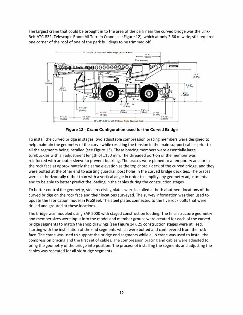
The largest crane that could be brought in to the area of the park near the curved bridge was the Link-Belt ATC-822, Telescopic Boom All Terrain Crane (see Figure 12), which at only 2.66 m wide, still required one corner of the roof of one of the park buildings to be trimmed off.
Figure 12 - Crane Configuration used for the Curved Bridge
To install the curved bridge in stages, two adjustable compression bracing members were designed to help maintain the geometry of the curve while resisting the tension in the main support cables prior to all the segments being installed (see Figure 13). These bracing members were essentially large turnbuckles with an adjustment length of ±150 mm. The threaded portion of the member was reinforced with an outer sleeve to prevent buckling. The braces were pinned to a temporary anchor in the rock face at approximately the same elevation as the top chord / deck of the curved bridge, and they were bolted at the other end to existing guardrail post holes in the curved bridge deck ties. The braces were set horizontally rather than with a vertical angle in order to simplify any geometry adjustments and to be able to better predict the loading in the cables during the construction stages.
To better control the geometry, steel receiving plates were installed at both abutment locations of the curved bridge on the rock face and their locations surveyed. The survey information was then used to update the fabrication model in ProSteel. The steel plates connected to the five rock bolts that were drilled and grouted at these locations.
The bridge was modeled using SAP 2000 with staged construction loading. The final structure geometry and member sizes were input into the model and member groups were created for each of the curved bridge segments to match the shop drawings (see Figure 14). 25 construction stages were utilized, starting with the installation of the end segments which were bolted and cantilevered from the rock face. The crane was used to support the bridge end segments while a jib crane was used to install the compression bracing and the first set of cables. The compression bracing and cables were adjusted to bring the geometry of the bridge into position. The process of installing the segments and adjusting the cables was repeated for all six bridge segments.

13
Figure 13 - Erection of the Curved Bridge
Figure 14 – SAP Model for Erecting the Curved Bridge
The modeling process was iterative as the required tensions in the cables were adjusted in each construction stage to achieve the required geometry. As well, final model deflections due to timber bridge deck, handrails and live loads were used to determine the required initial camber of the bridge to achieve a level geometry. Also checked in the model were the rock face anchor bolt loads during installation and service as well as local stresses on the anchor plates which were modeled using finite elements. A detailed 25 stage erection plan was prepared which included erection weights, crane reaches, estimated required tension in the cables and bridge erection working point coordinates. During erection, geometry was checked using a total station.

14
Figure 15 – Constructed Curved Bridge
Load Testing Load testing of the structure was completed on the curved bridge and two of the straight bridge segments. The straight bridges were common to a strut beam bolted to the rock face thereby producing the largest reaction on any of the strut beam foundations on the project. The load level that was chosen for the testing was 4.0 kPa to simulate the design live loading. Instrumentation used in the testing included vibrating wire strain gauges, thermometers, tilt meters and a cable tension meter. Loading was achieved by filling 45 gallon barrels with common tap water. The loading sequence was to fill every third barrel and then take readings of the instrumentation and conduct a visual inspection. Both the straight bridge and curved bridges were unloaded from one end to simulate checkerboard loading effects. The structures performed very well and the predicted forces in the cables were found to closely correlate with the measured values.
Closure The design and construction of the Cliffwalk has resulted in a visually appealing and unique “bridge” structure that reinforces the sustainable tourism model already in place at the Capilano Suspension Bridge Park (see Figure 15). It illustrates that structures can be successfully constructed to serve a purpose that goes above and beyond the utilitarian nature of most modern bridges. The project also serves to reinforce that teamwork on infrastructure projects is the best foundation for success, as this project was truly a collaborative effort from start to finish by all parties involved. Opened on June 3, 2011 the Cliffwalk has been received with many accolades.