Embed Size (px)
DESCRIPTION
Design and Construction of Enlarging Shield Tunnel Sections ofLarge Dimensional Shield Tunnels for the non-open-cut method
Citation preview
Design and Construction of Enlarging Shield Tunnel Sections of Large Dimensional Shield Tunnels for the non-open-cut method
Hiroshi Dobashi1, Akira Shiratori2, Daisuke Miyama1, Hiroshi Nagura3, Takuya Miyawaki4
1 First Design Group, Tokyo Construction Bureau, Metropolitan Expressway Co., Ltd.2 Structural Engineering Group, Engineering Management Office, Metropolitan Expressway Co., Ltd.3 First Engineering Department, Civil Engineering Division, Hazama Corporation4 Nishi-Shinjuku Work Office, Kanto Civil Engineering Branch, Hazama Corporation
ABSTRACT
The use of the enlarging method for large dimensional shield tunnel construction is essential in the building of branch connections and ramps, particularly when constructing underground roads in narrow urban areas. In this paper, the non-open-cut method, which excavates underground, used in The Central Circular Shinjuku Route of Tokyo Metropolitan Expressway is reported.This paper describes the construction of the cut and open of a part of steel segments installed in two-parallel large dimensional shield tunnels over a total length of 100 m using the non-open-cut method. The pipe roofing method was adopted for three reasons: the excavation depth is relatively shallow; the location is just beneath a trunk road intersection; and important utilities are laid underground at various locations. And, new construction methods such as use of pre-strutting, which involves the placement of preceding struts using pipe-jacking in order to stabilize the tunnels and to prevent deformation, as well as preloading to reduce settlement of roof pipes are employed. Furthermore, in order to ensure safety during the construction work and to reduce adverse environmental effects such as ground settlement, various types of behavior prediction analysis have been carried out and monitoring-feed backing to construction are performed as construction continues.
1. INTRODUCTION
1.1 Route plans and purpose of development
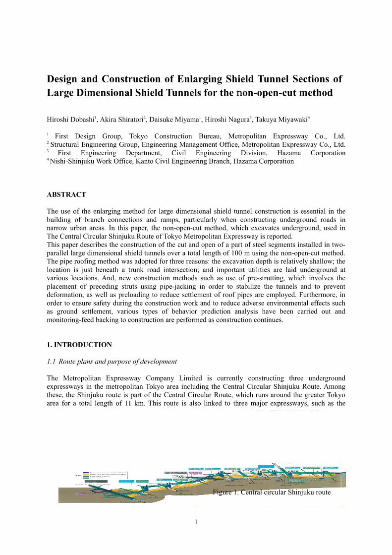
The Metropolitan Expressway Company Limited is currently constructing three underground expressways in the metropolitan Tokyo area including the Central Circular Shinjuku Route. Among these, the Shinjuku route is part of the Central Circular Route, which runs around the greater Tokyo area for a total length of 11 km. This route is also linked to three major expressways, such as the
1
Figure 1. Central circular Shinjuku route
Tomei Expressway, and has 6 entrances connecting it to main roads in the metropolitan area (refer to Figure 1). For about 70% of the sections, large dimensional shields of 11 m to 13 m in diameter were adopted for the first time instead of using the typical open-cut method. This was done in order to mitigate the adverse effects on the surrounding environment and to minimize interruptions to road traffic. In relation to this new construction method, various approaches were employed.
1.2 Enlarging shield tunnel construction at branch junctions
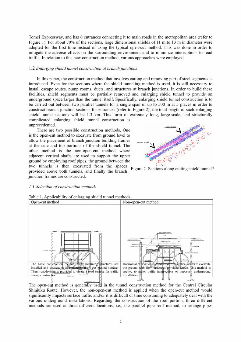
In this paper, the construction method that involves cutting and removing part of steel segments is introduced. Even for the sections where the shield tunneling method is used, it is still necessary to install escape routes, pump rooms, ducts, and structures at branch junctions. In order to build these facilities, shield segments must be partially removed and enlarging shield tunnel to provide an underground space larger than the tunnel itself. Specifically, enlarging shield tunnel construction is to be carried out between two parallel tunnels for a single span of up to 500 m at 5 places in order to construct branch junction sections for entrances (refer to Figure 2); the total length of such enlarging shield tunnel sections will be 1.3 km. This form of extremely long, large-scale, and structurally complicated enlarging shield tunnel construction is unprecedented.
There are two possible construction methods. One is the open-cut method to excavate from ground level to allow the placement of branch junction building frames at the side and top portions of the shield tunnel. The other method is the non-open-cut method where adjacent vertical shafts are used to support the upper ground by employing roof pipes, the ground between the two tunnels is then excavated from the spaces provided above both tunnels, and finally the branch junction frames are constructed.
1.3 Selection of construction methods
Table 1. Applicability of enlarging shield tunnel methodsOpen-cut method Non-open-cut method
The basic construction method. Earth retaining structures are installed and excavation is conducted from the ground surface. Then, roaddecking is provided to create a road surface for traffic during construction.
Horizontal excavation is conducted from vertical shafts to excavate the ground with roof structures provided above. This method is applied to major traffic intersections or important underground installations.
The open-cut method is generally used in the tunnel construction method for the Central Circular Shinjuku Route. However, the non-open-cut method is applied when the open-cut method would significantly impacts surface traffic and/or it is difficult or time consuming to adequately deal with the various underground installations. Regarding the construction of the roof portion, three different methods are used at three different locations, i.e., the parallel pipe roof method, to arrange pipes
2
main tunnel
junction tunnel
Figure 2. Sections along cutting shield tunnel1)
impervious wall
timbering
ground improvement
timbering
removal segment
ground improvement
ground improvement
23400
impervious wall
timberingtimberingtimbering
sewage culvert
underground pipes
impervious wall
ground improvement

parallel to the tunnels; the curved pipe roofing method, to arrange pipes in transverse directions; and the NATM method. This paper examines a typical non-open-cut method using roof pipes that run alongside the tunnels.
2. OUTLINE OF NON-OPEN-CUT CONSTRUCTION
2.1 Planning conditions
Use of the non-open-cut method in the construction of branch junction sections of the shield tunnels was undertaken to address the following conditions (refer to Figure 3):・ Under major intersections with large traffic
number・ Where there are a number of large underground
utilities and/or difficult-to-handle cables of special high voltage power lines
・ Relatively shallow earth covering of approximately 7 m
・ Complicated earth layers with gravel layer, sand layer, and clay layer as well as high groundwater level
・ Relatively large distance between the parallel tunnels to be enlarged, with a special cross-sectional configuration for the installation of ventilation ducts on top.
2.2 Determination of construction methods
The reason to be selected the non-open-cut method is not only because of the presence of a major intersection but also due to the difficulty of replacing underground pipelines, which carry special high voltage power lines. Furthermore, from various non-open-cut methods, the pipe roofing method was employed taking into account the shallow earth covering, short distance from underground installations, and complicated cross-sectional configuration (refer to Table 2 and Figure 4).
Table 2. Comparison of construction methodsPlan A: Open-cut method Non-open-cut methods
Plan B: Pipe roofing method Plan C: Curved boring + freezing method
Difficult to relocate and protect underground installations. As working hours at major intersections are restricted, it is disadvantageous in terms of both cost efficiency and construction period.
Roof pipes can be laid out straight while avoiding underground objects. No impacts on underground installations or surface road traffic. The most advantageous in terms of cost efficiency and construction period. (Applied)
With shallow earth covering, the arched roof can interfere with underground objects. The freezing method impacts the ground surface causing freezing and melting conditions.Cost efficiency and construction period are disadvantageous.
3
Figure 4. Rendering
Figure 3. Construction
underground pipespipe roof
underground pipesfrozen ground
frozen groundcurved boring
underground pipes
信
信
A - A
outside inside
1136
0
23232
boundaryboundary
2.3 Problems and solutions
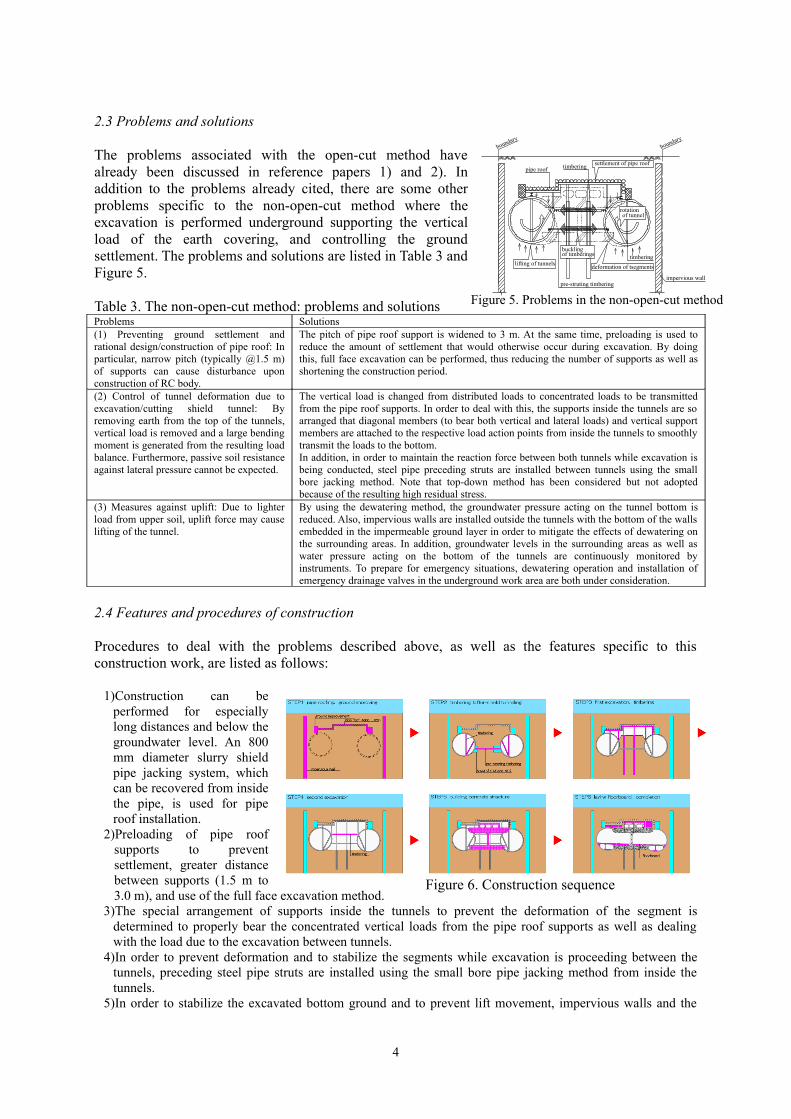
The problems associated with the open-cut method have already been discussed in reference papers 1) and 2). In addition to the problems already cited, there are some other problems specific to the non-open-cut method where the excavation is performed underground supporting the vertical load of the earth covering, and controlling the ground settlement. The problems and solutions are listed in Table 3 and Figure 5.
Table 3. The non-open-cut method: problems and solutionsProblems Solutions(1) Preventing ground settlement and rational design/construction of pipe roof: In particular, narrow pitch (typically @1.5 m) of supports can cause disturbance upon construction of RC body.
The pitch of pipe roof support is widened to 3 m. At the same time, preloading is used to reduce the amount of settlement that would otherwise occur during excavation. By doing this, full face excavation can be performed, thus reducing the number of supports as well as shortening the construction period.
(2) Control of tunnel deformation due to excavation/cutting shield tunnel: By removing earth from the top of the tunnels, vertical load is removed and a large bending moment is generated from the resulting load balance. Furthermore, passive soil resistance against lateral pressure cannot be expected.
The vertical load is changed from distributed loads to concentrated loads to be transmitted from the pipe roof supports. In order to deal with this, the supports inside the tunnels are so arranged that diagonal members (to bear both vertical and lateral loads) and vertical support members are attached to the respective load action points from inside the tunnels to smoothly transmit the loads to the bottom.In addition, in order to maintain the reaction force between both tunnels while excavation is being conducted, steel pipe preceding struts are installed between tunnels using the small bore jacking method. Note that top-down method has been considered but not adopted because of the resulting high residual stress.
(3) Measures against uplift: Due to lighter load from upper soil, uplift force may cause lifting of the tunnel.
By using the dewatering method, the groundwater pressure acting on the tunnel bottom is reduced. Also, impervious walls are installed outside the tunnels with the bottom of the walls embedded in the impermeable ground layer in order to mitigate the effects of dewatering on the surrounding areas. In addition, groundwater levels in the surrounding areas as well as water pressure acting on the bottom of the tunnels are continuously monitored by instruments. To prepare for emergency situations, dewatering operation and installation of emergency drainage valves in the underground work area are both under consideration.
2.4 Features and procedures of construction
Procedures to deal with the problems described above, as well as the features specific to this construction work, are listed as follows:
1)Construction can be performed for especially long distances and below the groundwater level. An 800 mm diameter slurry shield pipe jacking system, which can be recovered from inside the pipe, is used for pipe roof installation.
2)Preloading of pipe roof supports to prevent settlement, greater distance between supports (1.5 m to 3.0 m), and use of the full face excavation method.
3)The special arrangement of supports inside the tunnels to prevent the deformation of the segment is determined to properly bear the concentrated vertical loads from the pipe roof supports as well as dealing with the load due to the excavation between tunnels.
4)In order to prevent deformation and to stabilize the segments while excavation is proceeding between the tunnels, preceding steel pipe struts are installed using the small bore pipe jacking method from inside the tunnels.
5)In order to stabilize the excavated bottom ground and to prevent lift movement, impervious walls and the
4
impervious wall
rotationof tunnel
settlement of pipe roof
lifting of tunnels
pipe roof timbering
pre-struting timbering
boundaryboundary
timberingdeformation of tsegments
bucklingof timberings
Figure 6. Construction sequence
Figure 5. Problems in the non-open-cut method

dewatering method are used. The construction process that incorporates the above features are shown in Figure 6.
3. DESIGN OUTLINE
In implementing the closed-cut construction method, the following major design points were elaborated by the engineers: From these points, items (1), (2), (5), and (6) are introduced in this paper.
Table 4. Design items listItem Analysis Outline
(1) Upper pipe roof support
Elasto-plastic analysis of earth retaining structure
Specifications for the pipe roof system were defined based on the sectional stress to be generated. Also, reaction force was used to design the pipe roof supporting beams and other temporary structures such as intermediate piles.
(2)
Supports inside the segmentSupports between tunnels
Two-dimensional sequential FEM analysis
Cross-sections of each construction step were analyzed using two-dimensional sequential FEM analysis with the steel shells and supports regarded as beam elements and RC skeletons as solid elements.
(3)Design of the RC body at the shield tunnel is cut opened
Two-dimensional frame analysis
The RC body was designed using two-dimensional frame analysis. Three different design conditions were applied, i.e., ordinary, Level 1 earthquake, and Level 2 earthquake.
(4)Joints between RC body and steel segment lining
Two-dimensional sequential FEM analysisTwo dimensional frame analysis
Structural design was performed using sectional stress data obtained from (2) and from (3); the longitudinal ribs of the steel segment were used as the shear connector to reliably transfer the cross-sectional stress such as axial force and bending moment.
(5) Effects to peripheral ground
Two-dimensional FEM analysis
Two-dimensional FEM analysis was performed including that of underground installations to study the effects on peripheral ground.
(6) Total system behavior
Three-dimensional frame analysis
Three-dimensional frame analysis was performed modeling the roof pipes and their supports, the segment of supports inside the tunnels, supports between the tunnels.
3.1 Design of roof pipes by elasto-plastic analysis of earth retaining structure
“Elasto-plastic analysis of earth retaining structure” was performed in order to design the roof pipes. Sequential analysis was performed using a model in which roof pipes are regarded as earth retaining walls, the vertical load from the overburden pressure is regarded as lateral pressure, and vertical supports such as the intermediate piles and columns are regarded as struts. The subgrade reaction that can act on the pipes in the ground was regarded as that caused by an elasto-plastic spring of which the maximum spring force is set to the passive earth pressure considering the loosened zone. Using the stress resultants of earth retaining walls and the strut reaction obtained by the analysis, steel roof pipes and temporary support structures were designed and the displacement of roof pipes was estimated. As the displacement of roof pipes can directly impact ground surface settlement, hydraulic jacks were used for preloading the vertical supports to control the amount of settlement to within 19 mm. The preloading is set at 80% of the support reaction force, with a maximum of 2.4 MN per support.
3.2 Sequential analysis of shield tunnels
Because significant changes are expected in structural systems and acting loads during
5
Figure 7. Modeling for excavation analysis
earth pressure (with traffic load)
pre-loadingelastic springs elasto-plastic
h qΣγ +
springs
Deformation Momentexcavationcompleted
in-service
Figure 8. Result of sequential analysis
construction, and as it is important to predict the behavior of the structural system, two-dimensional sequential FEM analysis was performed for examining the segments, internal supports, supports between tunnels, and the joints of steel segments and RC body. The analysis was done mainly on frame elements ,as well as two-dimensional FEM analysis using solid elements in terms of RC body, and the processes from shield construction, tunnel excavation, cutting to open the segment, construction of the RC body, and the reduction of stiffness after completion of construction were considered (refer to Figure 8). The analysis method is described in detail in reference paper 1).
Three different sections were selected to represent typical structural configurations to reflect the differences in the distance between the tunnels, structural variations in the RC body, the plan showing the positions of pipe roof supports, and so on. Furthermore, numerous cases were subjected to analysis to study different loading conditions taking into account such conditions as whether the dewatering method is used or not. In this analysis, roof pipes and their supports were evaluated under concentrated vertical loads while stiffness was not taken into account.
The analysis results, such as stress resultants and deformation data, are used to decide the following: safe and cost effective construction procedures; checking on segment stress and deformation; design of joints to the RC body; and design of supports inside and between tunnels. The analysis results are also reflected in measurement control of segments, etc.
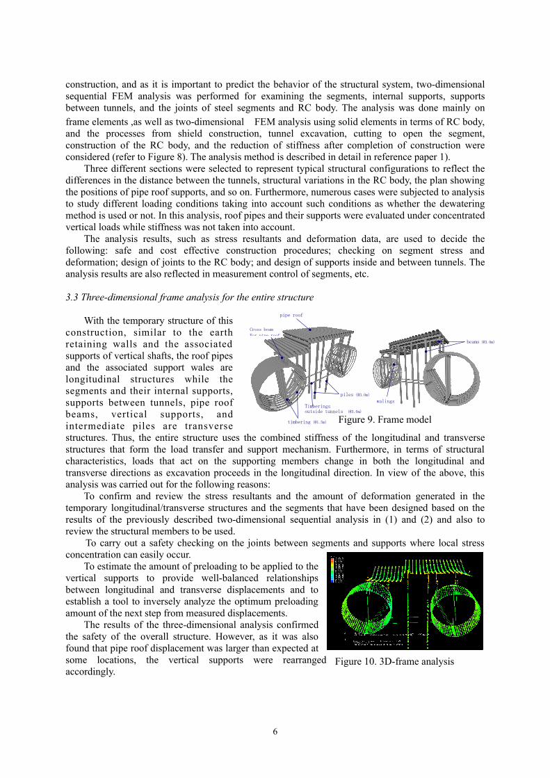
3.3 Three-dimensional frame analysis for the entire structure
With the temporary structure of this construction, similar to the earth retaining walls and the associated supports of vertical shafts, the roof pipes and the associated support wales are longitudinal structures while the segments and their internal supports, supports between tunnels, pipe roof beams, vertical supports, and intermediate piles are transverse structures. Thus, the entire structure uses the combined stiffness of the longitudinal and transverse structures that form the load transfer and support mechanism. Furthermore, in terms of structural characteristics, loads that act on the supporting members change in both the longitudinal and transverse directions as excavation proceeds in the longitudinal direction. In view of the above, this analysis was carried out for the following reasons:
To confirm and review the stress resultants and the amount of deformation generated in the temporary longitudinal/transverse structures and the segments that have been designed based on the results of the previously described two-dimensional sequential analysis in (1) and (2) and also to review the structural members to be used.
To carry out a safety checking on the joints between segments and supports where local stress concentration can easily occur.
To estimate the amount of preloading to be applied to the vertical supports to provide well-balanced relationships between longitudinal and transverse displacements and to establish a tool to inversely analyze the optimum preloading amount of the next step from measured displacements.
The results of the three-dimensional analysis confirmed the safety of the overall structure. However, as it was also found that pipe roof displacement was larger than expected at some locations, the vertical supports were rearranged accordingly.
6
Figure 10. 3D-frame analysis
Figure 9. Frame model
piles(@3.0m)
pipe roof
timbering(@1.5m)
Cross beam for pipe roof
Timberings outside tunnels (@3.0m)
beams(@3.0m)
walings
Cross beam
For pipe roof
4. CONSTRUCTION OUTLINE
As of October 2005, construction has reached Step 3 as shown in Figure 6. Now work to excavate under the roof pipes and driving piles has begun. Some unique features of the construction work are introduced in this section.
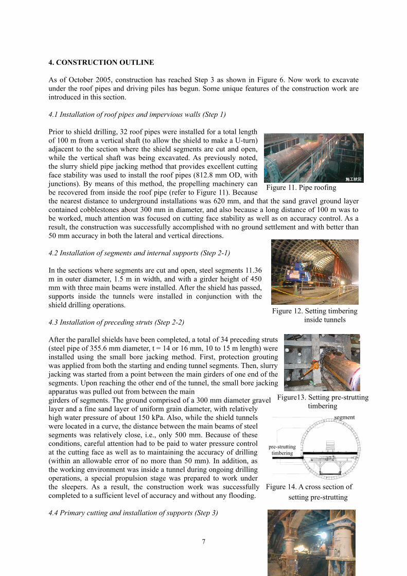
4.1 Installation of roof pipes and impervious walls (Step 1)
Prior to shield drilling, 32 roof pipes were installed for a total length of 100 m from a vertical shaft (to allow the shield to make a U-turn) adjacent to the section where the shield segments are cut and open, while the vertical shaft was being excavated. As previously noted, the slurry shield pipe jacking method that provides excellent cutting face stability was used to install the roof pipes (812.8 mm OD, with junctions). By means of this method, the propelling machinery can be recovered from inside the roof pipe (refer to Figure 11). Because the nearest distance to underground installations was 620 mm, and that the sand gravel ground layer contained cobblestones about 300 mm in diameter, and also because a long distance of 100 m was to be worked, much attention was focused on cutting face stability as well as on accuracy control. As a result, the construction was successfully accomplished with no ground settlement and with better than 50 mm accuracy in both the lateral and vertical directions.
4.2 Installation of segments and internal supports (Step 2-1)
In the sections where segments are cut and open, steel segments 11.36 m in outer diameter, 1.5 m in width, and with a girder height of 450 mm with three main beams were installed. After the shield has passed, supports inside the tunnels were installed in conjunction with the shield drilling operations.
4.3 Installation of preceding struts (Step 2-2)
After the parallel shields have been completed, a total of 34 preceding struts (steel pipe of 355.6 mm diameter, t = 14 or 16 mm, 10 to 15 m length) were installed using the small bore jacking method. First, protection grouting was applied from both the starting and ending tunnel segments. Then, slurry jacking was started from a point between the main girders of one end of the segments. Upon reaching the other end of the tunnel, the small bore jacking apparatus was pulled out from between the main girders of segments. The ground comprised of a 300 mm diameter gravel layer and a fine sand layer of uniform grain diameter, with relatively high water pressure of about 150 kPa. Also, while the shield tunnels were located in a curve, the distance between the main beams of steel segments was relatively close, i.e., only 500 mm. Because of these conditions, careful attention had to be paid to water pressure control at the cutting face as well as to maintaining the accuracy of drilling (within an allowable error of no more than 50 mm). In addition, as the working environment was inside a tunnel during ongoing drilling operations, a special propulsion stage was prepared to work under the sleepers. As a result, the construction work was successfully completed to a sufficient level of accuracy and without any flooding.
4.4 Primary cutting and installation of supports (Step 3)
7
Figure13. Setting pre-struttingtimbering
segment
pre-struttingtimbering
Figure 11. Pipe roofing
Figure 12. Setting timbering inside tunnels
Figure 14. A cross section of setting pre-strutting
From October 2005, excavation was started directly under the roof pipes. In order to reduce settlement of the pipes, it was necessary to make the cutting face slope steeper and to shorten the length of the drilling head. For this reason and to stabilize the cutting face, chemical grouting of the intervening sand layers was planned and executed from within the tunnels. At present, entrances are being installed in preparation for the subsequent excavation work.
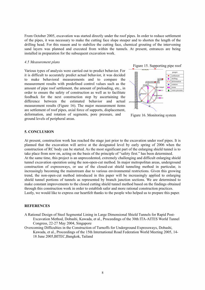
4.5 Measurement plans
Various types of analysis were carried out to predict behavior. For it is difficult to accurately predict actual behavior, it was decided to make behavioral measurements and to compare the measurement results with predefined control values such as the amount of pipe roof settlement, the amount of preloading, etc., in order to ensure the safety of construction as well as to facilitate feedback for the next construction step by ascertaining the difference between the estimated behavior and actual measurement results (Figure 16). The major measurement items are settlement of roof pipes, axial force of supports, displacement, deformation, and rotation of segments, pore pressure, and ground levels of peripheral areas.
5. CONCLUSION
At present, construction work has reached the stage just prior to the excavation under roof pipes. It is planned that the excavation will arrive at the designated level by early spring of 2006 when the construction of RC body can be started. As the most significant part of the enlarging shield tunnel is to take place from now on, acting on the basis of the principle of “safety first.” has been determined.At the same time, this project is an unprecedented, extremely challenging and difficult enlarging shield tunnel excavation operation using the non-open-cut method. In major metropolitan areas, underground construction of expressways, or use of the closed-cut shield tunneling method in particular, is increasingly becoming the mainstream due to various environmental restrictions. Given this growing trend, the non-open-cut method introduced in this paper will be increasingly applied to enlarging shield tunnel portions of tunnels as represented by branch junction sections. We are determined to make constant improvements to the closed cutting shield tunnel method based on the findings obtained through this construction work in order to establish safer and more rational construction practices.Lastly, we would like to express our heartfelt thanks to the people who helped us to prepare this paper.
REFERENCES
A Rational Design of Steel Segmental Lining in Large Dimensional Shield Tunnels for Rapid Post-Excavation Method, Dobashi, Kawada, et al., Proceedings of the 30th ITA-AITES World Tunnel Congress, 22-27 May 2004, Singapore
Overcoming Difficulties in the Construction of Turnoffs for Underground Expressways, Dobashi, Kawada, et al., Proceedings of the 15th International Road Federation World Meeting 2005, 14-18 June 2005,BITEC,Bangkok, Tailand
8
Figure 15. Supporting pipe roof
Figure 16. Monitoring system
settlement
gauges
shiftingdeformationrotationstrainwater pressure
laser ranger
strainmeter
pressure meter
tiltmeter
prism